Embed Size (px)
Citation preview

Cable Handbook
www.unipartrail.com/elandcables

For more information Tel +44 (0)1270 847 300 Fax +44 (0)1270 847 6922
Contents
Page3469
1114162534404549515456626871747677798184878990919293
IntroductionSignalling Cable Type A1, A2, A3Signalling Cable Type B1, B2Signalling Cable Type C1, C2, C3 TPWSSignalling Cable Type D1, D2Signalling Cable Type E1, E2, E3 TPWSSteel Wire Armoured PVC CableSteel Wire Armoured LSZH Cable11kV XLPE LSZH Cable11kV XPLE PVC Cable33kV CableAluminium Power CableMV Power CableTrackfeeder Cable6491B Cable6491X CableArmoured Copper Trackside CableCopper Trackside CableFibre Trackside CableFTN Screening Conductor CableSCADA / Pilot CableTwin Datalink CableSection 12 Fire Integrity Cable – London UndergroundFireforce Fire Performance Cable PH30Points Heating CableBare ConductorScreening Conductor PVC CableScreening Conductor LSZH CableCoaxial Cable URM70Accessories

[email protected] www.unipartrail.com/elandcables 3
Unipart Rail and Eland Cables offer one of the most comprehensive and competitive Network Rail approved cable portfolios in the industry. This includes everything from Signalling and Telecommunications Cable to Power and Points Heating Cable.
This Cable Handbook contains detailed listings of our entire rail product range. Following massive inventory investment, rail customers can benefit from guaranteed stockholding and immediate availability on ex-stock cables.
Having played an integral role in the development and maintenance of the UK’s rail network for more than a decade, Eland Cables and Unipart Rail are now working together as framework suppliers for Network Rail’s Project Synergy contract. This combines Eland Cables’ technical knowledge, sourcing expertise and established supplier relationships with Unipart Rail’s logistics, materials management and wider rail portfolio to provide you with unrivalled service.
Together, we are committed to delivering sustainable best value to our customers, supporting Network Rail and contributing towards the safety and efficiency of the UK’s railways.
Expect more from your rail cable supplier…
• Network Rail approved cables• Guaranteed stockholding• Immediate availability• Competitive prices• 24 hour emergency assistance• Remote warehouse for on-site materials management• Drum collection and recycling service• Downloadable specifications and 3D cables – available at www.unipartrail.com/elandcables
Call our dedicated sales team now on +44 (0)1270 847 300 or e-mail [email protected]
Welcome to our Cable Handbook

For more information Tel +44 (0)1270 847 300 Fax +44 (0)1270 847 6924
Signalling Cable Type A1, A2, A3
Application
Standards
Conductor
Insulation
Sheath
Sheath Colour
Voltage Rating
Light duty LSZH sheathed single and multi-core cables generally for internal use. Smooth sheath suitable for installation in ducting.
NR/PS/SIG/00005 (formerly RT/E/PS/00005)
Class 2 stranded tinned conductor to BS EN 60228:2005 (previously BS6360)
LSZH (Low Smoke Zero Halogen) orEPR (Ethylene Propylene Rubber) Composite (optional on Type A4)
LSZH (Low Smoke Zero Halogen)
Black
650/1100V
Temperature Rating -25°C to +85°C
Separator PETP (Polyethylene Terephthalate)

[email protected] www.unipartrail.com/elandcables 5
ConductorsClass 2 stranded conductors for single core and multi-core cables
1 2 3 4 5 6 7 9
Nominal Cross
Sectional Areamm²
Minimum Number of Wires in the Conductor Maximum Resistance of Conductor at 20ºC
Circular Circular Compacted
Shaped Annealed Copper Conductor
Cu Al Cu Al Cu AlMetal-Coated Wires
ohms/Km
0.75 7 - - - - - 24.8000
Table in accordance with BS EN 60228:2005 (previously BS6360).
Signalling Cable Type A1, A2, A3
DimensionsRail
Catalogue Number
Cable Type No. of Cores x Nominal
Cross Sectional
Area# x mm²
No. and Nominal
Diameter of Strands
#/mm
Thickness of Sheath
Min.mm
Overall Diameter
Min.mm
Overall Diameter
Max.mm
Nominal Weightkg/Km
006/120001 A1 (blue) 1 x 0.75 7/0.37 0.7 2.7 3.2 16
006/120002 A1 (brown) 1 x 0.75 7/0.37 0.7 2.7 3.2 16
006/120003 A1 (red) 1 x 0.75 7/0.37 0.7 2.7 3.2 16
006/120004 A1 (orange) 1 x 0.75 7/0.37 0.7 2.7 3.2 16
006/120005 A1 (grey) 1 x 0.75 7/0.37 0.7 2.7 3.2 16
006/120006 A1 (violet) 1 x 0.75 7/0.37 0.7 2.7 3.2 16
006/120007 A1 (black) 1 x 0.75 7/0.37 0.7 2.7 3.2 16
006/120008 A1 (black) 1 x 1.15 16/0.30 0.7 2.9 3.6 20
006/120020 A2 1 x 0.75 7/0.37 0.7 4.0 5.0 30
006/120024 A2 1 x 1.15 16/0.30 0.7 4.3 5.3 35
006/120040 A3 2 x 0.75 7/0.37 0.9 6.7 8.8 67
006/120041 A3 4 x 0.75 7/0.37 1.0 8.0 10.4 108
006/120042 A3 6 x 0.75 7/0.37 1.1 9.7 12.5 160
006/120043 A3 10 x 0.75 7/0.37 1.2 12.6 16.1 259
006/120044 A3 14 x 0.75 7/0.37 1.3 13.8 17.7 495
006/120045 A3 36 x 0.75 7/0.37 1.6 21.6 26.9 752
006/120046 A3 48 x 0.75 7/0.37 1.6 24.3 30.7 963

For more information Tel +44 (0)1270 847 300 Fax +44 (0)1270 847 6926
Signalling Cable Type B1, B2
Application
Standards
Conductor
Insulation
Sheath
Sheath Colour
Voltage Rating
Temperature Rating
Heavy duty EPR–insulated and High Density PCP–sheathed single, twin and multi-core cables
NR/PS/SIG/00005 (formerly RT/E/PS/00005)
Class 2 tinned conductor to BS EN 60228:2005 (previously BS6360)
EPR (Ethylene Propylene Rubber)Type GP4 to BS7655
HDPCP (High Density Polychloroprene) Type RS2 to BS7655
Black
650/1100V
-25°C to +85°C

[email protected] www.unipartrail.com/elandcables 7
DimensionsRail
Catalogue Number
Cable Type No. of Cores x Nominal Cross
Sectional Area
# x mm²
No. and Nominal Diameter
of Strands#/mm
NominalThickness of Sheath
mm
Overall Diameter
Min.mm
Overall Diameter
Max.mm
Nominal Weightkg/Km
006/120061 B1 1 x 2.50 7/0.67 2.0 7.2 8.9 34
006/120062 B1 1 x 10.00 7/1.35 2.0 9.4 11.8 205
006/120063 B1 1 x 35.00 19/1.53 2.0 12.9 16.1 495
006/120081 B2 2 x 1.50 7/0.53 2.0 9.4 12.1 151
006/120082 B2 2 x 2.50 7/0.67 2.0 10.5 13.1 187
006/120083 B2 2 x 10.00 7/1.35 2.0 15.0 18.7 448
006/120113 B2 2 x 16.00 7/1.70 2.0 16.7 20.9 627
006/120084 B2 2 x 35.00 19/1.53 2.2 22.3 27.8 1185
006/120085 B2 2 x 70.00 19/2.14 2.4 28.8 36.0 1904
006/120086 B2 2 x 95.00 19/2.52 2.6 33.2 41.5 2885
006/120087 B2 4 x 0.75 7/0.37 2.0 10.2 12.8 173
006/120088 B2 4 x 1.50 7/0.53 2.0 10.9 13.7 220
006/120089 B2 4 x 2.50 7/0.67 2.0 11.9 14.8 264
006/120090 B2 7 x 0.75 7/0.37 2.0 11.8 14.7 239
006/120091 B2 7 x 1.50 7/0.53 2.0 12.6 15.8 304
006/120092 B2 7 x 2.50 7/0.67 2.0 13.8 17.2 387
006/120093 B2 10 x 0.75 7/0.37 2.0 14.4 18.0 342
006/120094 B2 10 x 1.50 7/0.53 2.0 15.6 19.4 402
006/120095 B2 10 x 2.50 7/0.67 2.0 17.1 21.3 564
006/120096 B2 12 x 0.75 7/0.37 2.0 14.8 18.5 351
006/120111 B2 6 x 2 x 0.75 7/0.37 2.0 19.7 24.6 469
006/120097 B2 12 x 1.50 7/0.67 2.0 16.0 20.0 466
006/120098 B2 12 x 2.50 7/0.37 2.0 17.6 22.0 612
006/120099 B2 19 x 0.75 7/0.37 2.0 17.0 21.3 490
006/120100 B2 19 x 1.50 7/0.53 2.0 18.5 23.1 649
006/120101 B2 19 x 2.50 7/0.67 2.0 20.4 25.5 886
Signalling Cable Type B1, B2

For more information Tel +44 (0)1270 847 300 Fax +44 (0)1270 847 6928
Rail Catalogue Number
Cable Type No. of Cores x Nominal
Cross Sectional
Area# x mm²
No. and Nominal
Diameter of Strands
#/mm
NominalThickness of Sheath
mm
Overall Diameter
Min.mm
Overall Diameter
Max.mm
Nominal Weightkg/Km
006/120102 B2 27 x 0.75 7/0.37 2.0 20.1 25.1 637
006/120103 B2 27 x 1.50 7/0.53 2.2 22.2 27.8 850
006/120104 B2 27 x 2.50 7/0.67 2.2 24.6 30.7 1222
006/120105 B2 37 x 0.75 7/0.37 2.2 22.7 28.4 846
006/120106 B2 37 x 1.50 7/0.53 2.2 25.1 31.4 1185
006/120107 B2 37 x 2.50 7/0.67 2.4 27.8 34.7 2030
006/120108 B2 48 x 0.75 7/0.37 2.2 25.7 32.2 1083
006/120109 B2 48 x 1.50 7/0.53 2.4 28.1 35.1 1581
006/120110 B2 48 x 2.50 7/0.67 2.6 31.2 39.0 2010
Signalling Cable Type B1, B2
ConductorsClass 2 stranded conductors for single core and multi-core cables
1 2 3 4 5 6 7 9
Nominal Cross
Sectional Areamm²
Minimum Number of Wires in the Conductor Maximum Resistance of Conductor at 20ºC
Circular Circular Compacted
Shaped Annealed Copper Conductor
Cu Al Cu Al Cu AlMetal-Coated Wires
ohms/Km
0.75 7 - - - - - 24.8000
1.00 7 - - - - - 18.2000
1.50 7 - 6 - - - 12.2000
2.50 7 - 6 - - - 7.5600
4.00 7 - 6 - - - 4.7000
6.00 7 - 6 - - - 3.1100
10.00 7 7 6 6 - - 1.8400
16.00 7 7 6 6 - - 1.1600
35.00 7 7 6 6 6 6 0.5290
70.00 19 19 12 12 12 12 0.2700
95.00 19 19 15 15 15 15 0.1950
Table in accordance with BS EN 60228:2005 (previously BS6360).

[email protected] www.unipartrail.com/elandcables 9
Signalling Cable Type C1, C2, C3 TPWS
Application
Standards
Conductor
Insulation
Drain Wire
Separator
Sheath
Sheath Colour
Heavy duty signalling cable suitable for tails.
NR/PS/SIG/00005(formerly RT/E/PS/00005)
Class 5 tinned conductor to BS EN 60228:2005 (previously BS6360)
EPR (Ethylene Propylene Rubber)Type GP4 to BS7655
Type C3 only
PETP (Polyethylene Terephthalate)
HDPCP (High Density Polychloroprene) Type RS2 to BS7655
Black
Voltage Rating
Temperature Rating
650/1100V
-25°C to +85°C

For more information Tel +44 (0)1270 847 300 Fax +44 (0)1270 847 69210
DimensionsRail
Catalogue Number
Cable Type No. of Cores x Nominal
Cross Sectional
Area# x mm²
No. and Nominal
Diameter of Strands
#/mm
NominalThickness of Sheath
mm
Overall Diameter
Min.mm
Overall Diameter
Max.mm
Nominal Weightkg/Km
006/120130 C1 1 x 2.5 50/0.25 3.8 11.2 14.0 174
006/120140 C2 2 x 2.5 50/0.25 3.8 14.9 18.8 338
006/120141 C2 4 x 2.5 50/0.25 3.8 16.4 20.9 450
006/120142 C2 7 x 2.5 50/0.25 3.8 18.7 23.7 612
006/120143 C2 10 x 2.5 50/0.25 3.8 22.5 28.6 836
006/120144 C2 12 x 2.5 50/0.25 3.8 23.2 29.3 909
006/160086 C3 TPWS 1 x 2 x 2.5 50/0.25 3.8 15.0 20.0 341
ConductorsClass 5 flexible copper conductors for single core and multi-core cables
1 2 4
Nominal Cross Sectional Areamm²
Maximum Diameter of Wires in the Conductor
mm²
Maximum Resistance of Conductor at 20ºC
Metal-Coated Wiresohms/Km
2.50 0.26 8.2100
Table in accordance with BS EN 60228:2005 (previously BS6360).
Signalling Cable Type C1, C2, C3 TPWS

[email protected] www.unipartrail.com/elandcables 11
Signalling Cable Type D1, D2
Application
Standards
Conductor
Insulation
Separator
Sheath
Sheath Colour
LSZH single, twin and multi-core cables.
NR/PS/SIG/00005(formerly RT/E/PS/00005)
Class 2 tinned conductor to BS EN 60228:2005 (previously BS6360)
LSZH (Low Smoke Zero Halogen) or EPR (Ethylene Propylene Rubber)
PETP (Polyethylene Terephthalate)
LSZH (Low Smoke Zero Halogen)
Black
Voltage Rating
Temperature Rating
650/1100V
-25°C to +85°C

For more information Tel +44 (0)1270 847 300 Fax +44 (0)1270 847 69212
DimensionsRail
Catalogue Number
Cable Type No. of Cores x Nominal
Cross Sectional
Area# x mm²
No. and Nominal
Diameter of Strands
#/mm
NominalThickness of Sheath
mm
Overall Diameter
Min.mm
Overall Diameter
Max.mm
Nominal Weightkg/Km
006/120213 D1 1 x 2.50 7/0.67 2.0 7.2 8.9 34
006/120214 D1 1 x 10.00 7/1.35 2.0 9.4 11.8 205
006/120215 D1 1 x 35.00 19/1.53 2.0 12.9 16.1 495
006/120217 D2 2 x 2.50 7/0.67 2.0 10.5 13.1 170
006/120218 D2 2 x 10.00 7/1.35 2.0 15.0 18.7 443
006/120226 D2 2 x 16.00 7/1.70 2.0 16.7 20.9 625
006/120219 D2 2 x 35.00 19/1.53 2.2 22.3 27.8 1232
006/120221 D2 2 x 95.00 19/2.52 2.6 33.2 41.5 2945
006/120222 D2 4 x 0.75 7/0.37 2.0 10.2 12.8 150
006/120227 D2 7 x 0.75 7/0.37 2.0 11.8 14.7 225
006/120229 D2 7 x 2.50 7/0.67 2.0 13.8 17.2 500
006/120230 D2 10 x 0.75 7/0.37 2.0 14.4 18.0 280
006/120233 D2 12 x 0.75 7/0.37 2.0 14.8 18.5 321
006/120235 D2 12 x 2.50 7/0.67 2.0 17.6 22.0 613
006/120236 D2 19 x 0.75 7/0.37 2.0 17.0 21.3 425
006/120210 D2 19 x 2.50 7/0.67 2.0 20.4 25.5 815
006/120238 D2 27 x 0.75 7/0.37 2.0 20.1 25.1 606
006/120239 D2 27 x 1.50 7/0.53 2.2 22.2 27.8 897
006/120241 D2 37 x 0.75 7/0.37 2.2 22.7 28.4 786
006/120242 D2 37 x 1.50 7/0.53 2.2 25.1 31.4 1126
006/120244 D2 48 x 0.75 7/0.37 2.2 25.7 32.2 972
006/120245 D2 48 x 1.50 7/0.53 2.4 28.1 35.1 1280
006/120246 D2 48 x 2.50 7/0.67 2.6 31.2 39.0 1960
Signalling Cable Type D1, D2

[email protected] www.unipartrail.com/elandcables 13
ConductorsClass 2 stranded conductors for single core and multi-core cables
1 2 3 4 5 6 7 9
Nominal Cross
Sectional Areamm²
Minimum Number of Wires in the Conductor Maximum Resistance of Conductor at 20ºC
Circular Circular Compacted
Shaped Annealed Copper Conductor
Cu Al Cu Al Cu AlMetal-Coated Wires
ohms/Km
0.75 7 - - - - - 24.8000
1.00 7 - - - - - 18.2000
1.50 7 - 6 - - - 12.2000
2.50 7 - 6 - - - 7.5600
4.00 7 - 6 - - - 4.7000
6.00 7 - 6 - - - 3.1100
10.00 7 7 6 6 - - 1.8400
16.00 7 7 6 6 - - 1.1600
35.00 7 7 6 6 6 6 0.5290
70.00 19 19 12 12 12 12 0.2700
95.00 19 19 15 15 15 15 0.1950
Table in accordance with BS EN 60228:2005 (previously BS6360).
Signalling Cable Type D1, D2

For more information Tel +44 (0)1270 847 300 Fax +44 (0)1270 847 69214
Signalling Cable Type E1, E2, E3 TPWS
Application
Standards
Conductor
Insulation
Drain Wire
Separator
Sheath
Sheath Colour
LSZH signalling cable suitable for tails.
NR/PS/SIG/00005(formerly RT/E/PS/00005)
Class 5 tinned conductor to BS EN 60228:2005 (previously BS6360)
LSZH (Low Smoke Zero Halogen) or EPR (Ethylene Propylene Rubber)
Type E3 only
PETP (Polyethylene Terephthalate)
LSZH (Low Smoke Zero Halogen)
Black
Voltage Rating
Temperature Rating
650/1100V
-25°C to +85°C

[email protected] www.unipartrail.com/elandcables 15
DimensionsRail
Catalogue Number
Cable Type No. of Cores x Nominal
Cross Sectional
Area# x mm²
No. and Nominal
Diameter of Strands
#/mm
NominalThickness of Sheath
mm
Overall Diameter
Min.mm
Overall Diameter
Max.mm
Nominal Weightkg/Km
006/120172 E1 1 x 2.5 50/0.25 3.8 11.2 14.0 174
006/120170 E2 2 x 2.5 50/0.25 3.8 14.9 18.8 359
006/120171 E2 4 x 2.5 50/0.25 3.8 16.4 20.9 445
006/120173 E2 7 x 2.5 50/0.25 3.8 18.7 23.7 590
006/120174 E2 10 x 2.5 50/0.25 3.8 22.5 28.6 784
006/120175 E2 12 x 2.5 50/0.25 3.8 23.2 29.3 868
Conductors
Signalling Cable Type E1, E2, E3 TPWS
Class 5 flexible Copper Conductors for single core and multi-core cables
1 2 4
Nominal Cross Sectional Areamm²
Maximum Diameter of Wires in Conductor
mm²
Maximum Resistance of Conductor at 20ºC
Metal-Coated Wiresohms/Km
2.50 0.26 8.2100
Table in accordance with BS EN 60228:2005 (previously BS6360).

For more information Tel +44 (0)1270 847 300 Fax +44 (0)1270 847 69216
Steel Wire Armoured PVC Cable
Application
Standards
Conductor
Insulation
Bedding
Armouring
Sheath
Sheath Colour
SWA Cable — power and auxiliary control cables for use in power networks, underground, outdoor and indoor applications and in cable ducting.
BS5467, IEC 60502
Class 2 plain stranded copper conductor to BS EN 60228:2005 (previously BS6360)
XLPE (Cross-Linked Polyethylene)
PVC (Polyvinyl Chloride)
Single core: AWA (Aluminium Wire Armour)Multi-core: SWA (Steel Wire Armour)
PVC (Polyvinyl Chloride)
Black
Voltage Rating
Temperature Rating
Minimum Bending Radius
600/1000V
0°C to +90°C
1.5mm² - 16mm²:6 x overall diameter
25mm² and above:8 x overall diameter

[email protected] www.unipartrail.com/elandcables 17
Dimensions
Steel Wire Armoured PVC Cable
No. of Cores x Nominal Cross Sectional Area
# x mm²
Nominal Thickness of Insulation
mm
Nominal Diameter mm Nominal Weightkg/Km
Under Armour Overall
Aluminium Wire Armoured PVC – 1 Core
1 x 50 1.0 12.7 17.5 800
1 x 70 1.1 14.7 20.2 960
1 x 95 1.1 16.6 22.3 1240
1 x 120 1.2 18.5 24.2 1510
1 x 150 1.4 20.8 27.4 1900
1 x 185 1.6 23.2 30.0 2320
1 x 240 1.7 26.0 32.8 2930
1 x 300 1.8 28.6 35.6 3580
1 x 400 2.0 32.4 40.4 4600
1 x 500 2.2 36.0 44.2 5770
1 x 630 2.4 40.0 48.8 7250
1 x 800 2.6 45.6 55.4 9381
1 x 1000 2.8 50.6 60.6 11540
Core Identification 1 Core: Brown2 Cores: Brown, Blue3 Cores: Brown, Black, Grey4 Cores: Blue, Brown, Black, Grey5 Cores: Green/Yellow, Blue, Brown, Black, Grey
Alternative core identification:White cores with Black numbers
BS5467 XLPE/PVC/AWA/PVC (Copper)
No. of Cores x Nominal Cross Sectional Area
# x mm²
Nominal Thickness of Insulation
mm
Nominal Diameter mm Nominal Weightkg/Km
Under Armour Overall
Steel Wire Armoured PVC – 2 Cores
2 x 1.5 0.6 7.3 12.1 302
2 x 2.5 0.7 8.5 13.6 346
2 x 4.0 0.7 9.4 14.7 410
2 x 6.0 0.7 10.5 15.9 499
BS5467 XLPE/PVC/SWA/PVC (Copper)

For more information Tel +44 (0)1270 847 300 Fax +44 (0)1270 847 69218
Steel Wire Armoured PVC Cable
No. of Cores x Nominal Cross Sectional Area
# x mm²
Nominal Thickness of Insulation
mm
Nominal Diameter mm Nominal Weightkg/Km
Under Armour Overall
Steel Wire Armoured PVC – 2 Cores
2 x 10.0 0.7 12.3 18.0 648
2 x 16.0 0.7 14.3 20.4 978
2 x 25.0 0.9 14.7 20.4 1290
2 x 35.0 0.9 16.8 23.3 1500
2 x 50.0 1.0 19.0 25.8 1890
2 x 70.0 1.1 22.0 29.0 2450
2 x 95.0 1.1 25.1 33.1 3300
2 x 150.0 1.4 30.9 39.3 4750
Steel Wire Armoured PVC – 3 Cores
3 x 1.5 0.6 7.8 12.6 330
3 x 2.5 0.7 9.2 14.1 390
3 x 4.0 0.7 10.0 15.3 464
3 x 6.0 0.7 11.2 16.6 568
3 x 10.0 0.7 13.1 19.5 866
3 x 16.0 0.7 15.3 21.6 1152
3 x 25.0 0.9 18.9 25.5 1800
3 x 35.0 0.9 21.3 28.0 2230
3 x 50.0 1.0 21.7 28.5 2490
3 x 70.0 1.1 25.2 32.2 3290
3 x 95.0 1.1 28.8 37.0 4440
Steel Wire Armoured PVC – 4 Cores
4 x 1.5 0.6 8.5 13.5 365
4 x 2.5 0.7 9.9 15.0 438
4 x 4.0 0.7 11.0 16.4 532
4 x 6.0 0.7 12.3 18.7 764
4 x 10.0 0.7 14.5 21.1 1013
4 x 16.0 0.7 17.0 22.9 1360
4 x 25.0 0.9 21.0 27.6 2160
4 x 35.0 0.9 23.6 30.4 2690
4 x 50.0 1.0 25.0 32.0 3130
4 x 70.0 1.1 29.5 37.7 4500
4 x 95.0 1.1 33.3 41.7 5600
BS5467 XLPE/PVC/SWA/PVC (Copper)

[email protected] www.unipartrail.com/elandcables 19
Steel Wire Armoured PVC Cable
No. of Cores x Nominal Cross Sectional Area
# x mm²
Nominal Thickness of Insulation
mm
Nominal Diameter mm Nominal Weightkg/Km
Under Armour Overall
Steel Wire Armoured PVC – 4 Cores
4 x 120.0 1.2 37.5 47.1 7400
4 x 150.0 1.4 41.6 51..4 8780
4 x 185.0 1.6 46.4 56.6 10630
4 x 240.0 1.7 52.6 63.0 13390
4 x 300.0 1.8 58.0 68.8 16290
4 x 400.0 2.0 65.4 78.1 19800
Steel Wire Armoured PVC – 5 Cores
5 x 1.5 0.6 9.7 14.3 410
5 x 2.5 0.7 11.7 16.3 470
5 x 4.0 0.7 13.0 17.8 710
5 x 6.0 0.7 14.5 20.0 876
5 x 10.0 0.7 17.2 22.9 1165
5 x 16.0 0.7 20.0 26.6 1742
5 x 25.0 0.9 24.7 31.5 2323
5 x 35.0 0.9 27.8 34.8 2932
5 x 50.0 1.0 32.4 40.4 4192
Steel Wire Armoured PVC – 7 Cores
7 x 1.5 0.6 10.2 15.2 470
7 x 2.5 0.7 12.3 17.1 600
Steel Wire Armoured PVC – 12 Cores
12 x 1.5 0.6 13.7 19.4 780
12 x 2.5 0.7 16.3 22.4 1000
Steel Wire Armoured PVC – 19 Cores
19 x 1.5 0.6 16.2 22.2 1000
19 x 2.5 0.7 19.9 26.6 1540
Steel Wire Armoured PVC – 27 Cores
27 x 1.5 0.6 20.0 26.7 1500
27 x 2.5 0.7 24.0 30.7 1950
Steel Wire Armoured PVC – 37 Cores
37 x 1.5 0.6 22.3 29.0 1800
37 x 2.5 0.7 26.9 33.8 2350
BS5467 XLPE/PVC/SWA/PVC (Copper)

For more information Tel +44 (0)1270 847 300 Fax +44 (0)1270 847 69220
Steel Wire Armoured PVC Cable
Table in accordance with BS EN 60228:2005 (previously BS6360).
ConductorsClass 2 stranded conductors for single core and multi-core cables
1 2 3 4 5 6 7 8
Nominal Cross
Sectional Areamm²
Minimum Number of Wires in the ConductorMaximum Resistance of Conductor
at 20ºC
Circular Circular Compacted Shaped Annealed Copper Conductor
Cu Al Cu Al Cu AlPlain Wires
ohms/Km
1.50 7 - 6 - - - 12.1000
2.50 7 - 6 - - - 7.4100
4.00 7 - 6 - - - 4.6100
6.00 7 - 6 - - - 3.0800
10.00 7 7 6 6 - - 1.8300
16.00 7 7 6 6 - - 1.1500
25.00 7 7 6 6 6 6 0.7270
35.00 7 7 6 6 6 6 0.5240
50.00 19 19 6 6 6 6 0.3870
70.00 19 19 12 12 12 12 0.2680
95.00 19 19 15 15 15 15 0.1930
120.00 37 37 18 15 18 15 0.1530
150.00 37 37 18 15 18 15 0.1240
185.00 37 37 30 30 30 30 0.0991
240.00 37 37 34 30 34 30 0.0754
300.00 61 61 34 30 34 30 0.0601
400.00 61 61 53 53 53 53 0.0470

[email protected] www.unipartrail.com/elandcables 21
Conductor Cross
Sectional Areamm²
Reference Method C (clipped direct)
Reference Method F(in free air or on a perforated cable tray, horizontal or vertical)
Touching Touching Spaced by One Cable Diameter
2 Cables Single Phase AC or
DC Flat Amps
3 or 4 Cables Three Phase
AC Flat
Amps
2 Cables Single Phase AC or
DC Flat Amps
3 Cables Three Phase
AC Flat
Amps
3 Cables Three Phase
AC Trefoil Amps
2 Cables DCAmps
2 Cables Single Phase AC
Amps
3 or 4 Cables Three Phase AC
Amps
Horizontal Vertical Horizontal Vertical Horizontal Vertical
1 2 3 4 5 6 7 8 9 10 11 12
50 237 220 253 232 222 284 270 282 266 288 266
70 303 277 322 293 285 356 349 357 337 358 331
95 367 333 389 352 346 446 426 436 412 425 393
120 425 383 449 405 402 519 497 504 477 485 449
150 488 437 516 462 463 600 575 566 539 549 510
185 557 496 587 524 529 688 660 643 614 618 574
240 656 579 689 612 625 815 782 749 714 715 666
300 755 662 792 700 720 943 906 842 805 810 755
400 853 717 899 767 815 1137 1094 929 889 848 797
500 962 791 1016 851 918 1314 1266 1032 989 923 871
630 1082 861 1146 935 1027 1528 1474 1139 1092 992 940
800 1170 904 1246 987 1119 1809 1744 1204 1155 1042 978
1000 1261 961 1345 1055 1214 2100 2026 1289 1238 1110 1041
Current Carrying Capacity (amperes)
Ambient temperature: 30°CConductor operating temperature: 90°C
1. Where a conductor operates at a temperature exceeding 70°C, it must be ascertained that the equipment connected to the conductor is suitable for the conductor operating temperature (see Regulation 512.1.2).
2. Where cables in this table are connected to equipment or accessories designed to operate at a temperature not exceeding 70°C, the current ratings given in the equivalent table for 70°C thermoplastic insulated cables (Table 4D3A) must be used. (see Regulation 523.1).
The above table is in accordance with Table 4E3A of the 17th Edition of IEE Wiring Regulations.
Steel Wire Armoured PVC Cable Cable
Electrical Characteristics XLPE/PVC/AWA/PVC
For more information Tel +44 (0)1270 847 300 Fax +44 (0)1270 847 69222
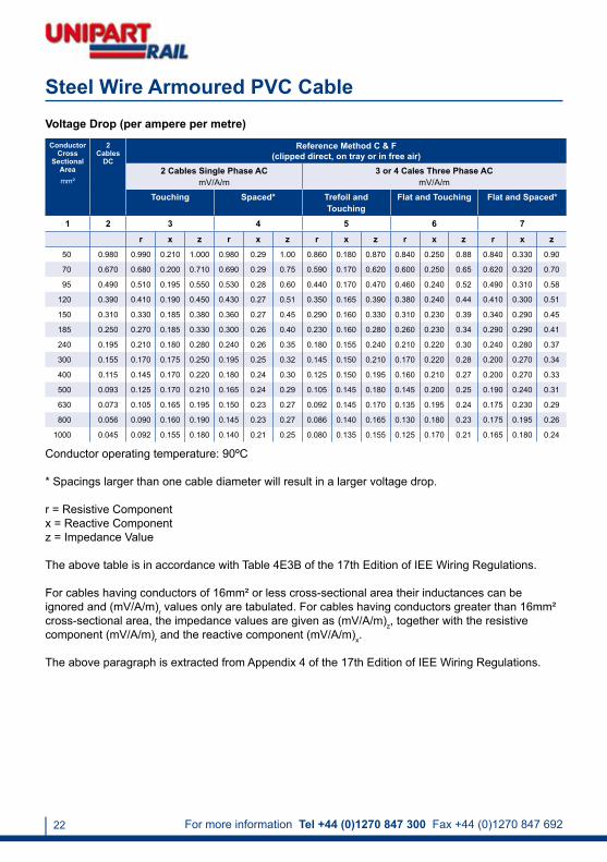
Steel Wire Armoured PVC CableVoltage Drop (per ampere per metre)
Conductor Cross
Sectional Areamm²
2 Cables
DC
Reference Method C & F(clipped direct, on tray or in free air)
2 Cables Single Phase ACmV/A/m
3 or 4 Cales Three Phase ACmV/A/m
Touching Spaced* Trefoil and Touching
Flat and Touching Flat and Spaced*
1 2 3 4 5 6 7
r x z r x z r x z r x z r x z50 0.980 0.990 0.210 1.000 0.980 0.29 1.00 0.860 0.180 0.870 0.840 0.250 0.88 0.840 0.330 0.90
70 0.670 0.680 0.200 0.710 0.690 0.29 0.75 0.590 0.170 0.620 0.600 0.250 0.65 0.620 0.320 0.70
95 0.490 0.510 0.195 0.550 0.530 0.28 0.60 0.440 0.170 0.470 0.460 0.240 0.52 0.490 0.310 0.58
120 0.390 0.410 0.190 0.450 0.430 0.27 0.51 0.350 0.165 0.390 0.380 0.240 0.44 0.410 0.300 0.51
150 0.310 0.330 0.185 0.380 0.360 0.27 0.45 0.290 0.160 0.330 0.310 0.230 0.39 0.340 0.290 0.45
185 0.250 0.270 0.185 0.330 0.300 0.26 0.40 0.230 0.160 0.280 0.260 0.230 0.34 0.290 0.290 0.41
240 0.195 0.210 0.180 0.280 0.240 0.26 0.35 0.180 0.155 0.240 0.210 0.220 0.30 0.240 0.280 0.37
300 0.155 0.170 0.175 0.250 0.195 0.25 0.32 0.145 0.150 0.210 0.170 0.220 0.28 0.200 0.270 0.34
400 0.115 0.145 0.170 0.220 0.180 0.24 0.30 0.125 0.150 0.195 0.160 0.210 0.27 0.200 0.270 0.33
500 0.093 0.125 0.170 0.210 0.165 0.24 0.29 0.105 0.145 0.180 0.145 0.200 0.25 0.190 0.240 0.31
630 0.073 0.105 0.165 0.195 0.150 0.23 0.27 0.092 0.145 0.170 0.135 0.195 0.24 0.175 0.230 0.29
800 0.056 0.090 0.160 0.190 0.145 0.23 0.27 0.086 0.140 0.165 0.130 0.180 0.23 0.175 0.195 0.26
1000 0.045 0.092 0.155 0.180 0.140 0.21 0.25 0.080 0.135 0.155 0.125 0.170 0.21 0.165 0.180 0.24
Conductor operating temperature: 90ºC
* Spacings larger than one cable diameter will result in a larger voltage drop.
r = Resistive Componentx = Reactive Componentz = Impedance Value
The above table is in accordance with Table 4E3B of the 17th Edition of IEE Wiring Regulations.
For cables having conductors of 16mm² or less cross-sectional area their inductances can be ignored and (mV/A/m)r values only are tabulated. For cables having conductors greater than 16mm² cross-sectional area, the impedance values are given as (mV/A/m)z, together with the resistive component (mV/A/m)r and the reactive component (mV/A/m)x.
The above paragraph is extracted from Appendix 4 of the 17th Edition of IEE Wiring Regulations.

[email protected] www.unipartrail.com/elandcables 23
Steel Wire Armoured PVC Cable
Current Carrying Capacity (amperes)
Conductor Cross
Sectional Areamm²
Reference Method C(clipped direct)
Amps
Reference Method E(in free air or on
a perforated cable tray, horizontal or vertical)
Amps
Reference Method D(direct in ground or in
ducting in ground, in or around buildings)
Amps
1 Two Core Cable Single
Phase AC or DC
1 Three or 1 Four Core Cable Three Phase AC
1 Two Core Cable Single
Phase AC or DC
1 Three or 1 Four Core Cable Three Phase AC
1 Two Core Cable Single
Phase AC or DC
1 Three or 1 Four Core Cable Three Phase AC
1 2 3 4 5 6 7
1.5 27 23 29 25 25 21
2.5 36 31 39 33 33 28
4.0 49 42 52 44 43 36
6.0 62 53 66 56 53 44
10.0 85 73 90 78 71 58
16.0 110 94 115 99 91 75
25.0 146 124 152 131 116 96
35.0 180 154 188 162 139 115
50.0 219 187 228 197 164 135
70.0 279 238 291 251 203 167
95.0 338 289 354 304 239 197
120.0 392 335 410 353 271 223
150.0 451 386 472 406 306 251
185.0 515 441 539 463 343 281
240.0 607 520 636 546 395 324
300.0 698 599 732 628 446 365
400.0 787 673 847 728 - -
Air ambient temperature: 30°CGround ambient temperature: 20°CConductor operating temperature: 90°C
1. Where a conductor operates at a temperature exceeding 70°C, it must be ascertained that the equipment connected to the conductor is suitable for the conductor operating temperature (see Regulation 512.1.2).
2. Where cables in this table are connected to equipment or accessories designed to operate at a temperature not exceeding 70°C, the current ratings given in the equivalent table for 70°C thermoplastic insulated cables (Table 4D4A) must be used (see Regulation 523.1).
The above table is in accordance with table 4E4A of the 17th Edition of IEE Wiring Regulations.
Electrical Characteristics XLPE/PVC/AWA/PVC

For more information Tel +44 (0)1270 847 300 Fax +44 (0)1270 847 69224
Steel Wire Armoured PVC CableVoltage Drop (per ampere per metre)
Conductor operating temperature: 90ºC
r = Resistive Componentx = Reactive Componentz = Impedance Value
The above table is in accordance with Table 4E4B of the 17th Edition of IEE Wiring Regulations.
For cables having conductors of 16mm² or less cross-sectional area their inductances can be ignored and (mV/A/m)r values only are tabulated. For cables having conductors greater than 16mm² cross-sectional area, the impedance values are given as (mV/A/m)r, together with the resistive component (mV/A/m)z and the reactive component (mV/A/m)x.
The above paragraph is extracted from Appendix 4 of the 17th Edition of IEE Wiring Regulations.
Conductor Cross
Sectional Areamm²
Two Core Cable DC
Two Core Cable Single Phase AC
mV/A/m
Three or Four Core Cable Three Phase AC
mV/A/m
1 2 3 4
1.5 31.000 31.0 27.0
2.5 19.000 19.0 16.0
4.0 12.000 12.0 10.0
6.0 7.900 7.9 6.8
10.0 4.700 4.7 4.0
16.0 2.900 2.9 2.5
r x z r x z
25.0 1.850 1.85 0.160 1.900 1.600 0.140 1.650
35.0 1.350 1.35 0.155 1.350 1.150 0.135 1.150
50.0 0.980 0.99 0.155 1.000 0.860 0.135 0.870
70.0 0.670 0.67 0.150 0.069 0.590 0.130 0.600
95.0 0.490 0.50 0.150 0.052 0.430 0.130 0.450
120.0 0.390 0.40 0.145 0.420 0.340 0.130 0.370
150.0 0.310 0.32 0.145 0.350 0.280 0.125 0.300
185.0 0.250 0.26 0.145 0.290 0.220 0.125 0.260
240.0 0.195 0.20 0.140 0.240 0.175 0.125 0.210
300.0 0.155 0.16 0.140 0.210 0.140 0.120 0.185
400.0 0.120 0.13 0.140 0.190 0.115 0.120 0.165

[email protected] www.unipartrail.com/elandcables 25
Steel Wire Armoured LSZH Cable
Application
Standards
Conductor
Insulation
Bedding
Armouring
Sheath
Sheath Colour
SWA Cable – power and auxiliary control cables for use in power networks, underground, outdoor and indoor applications and in cable ducting. For installation where fire, smoke emission and toxic fumes create a potential threat to life and equipment.
BS6724
Class 2 plain stranded copper conductor to BS EN 60228:2005 (previously BS6360)
XLPE (Cross-Linked Polyethylene)
LSZH (Low Smoke Zero Halogen)
Single core: AWA (Aluminium Wire Armour)Multi-core: SWA (Steel Wire Armour)
LSZH (Low Smoke Zero Halogen)
Black
Voltage Rating
Temperature Rating
Minimum Bending Radius
600/1000V
0°C to +90°C
1.5mm² - 16mm²:6 x overall diameter
25mm² and above:8 x overall diameter

For more information Tel +44 (0)1270 847 300 Fax +44 (0)1270 847 69226
DimensionsNo. of Cores x Nominal Cross Sectional Area
# x mm²
Nominal Thickness of Insulation
mm
Nominal Diameter mm
Nominal Weightkg/Km
Under Armour Overall
Aluminium Wire Armoured LSZH – 1 Core
1 x 50 1.0 12.7 17.5 800
1 x 70 1.1 14.7 20.2 960
1 x 95 1.1 16.6 22.3 1240
1 x 120 1.2 18.5 24.2 1510
1 x 150 1.4 20.8 27.4 1900
1 x 185 1.6 23.2 30.0 2320
1 x 240 1.7 26.0 32.8 2930
1 x 300 1.8 28.6 35.6 3580
1 x 400 2.0 32.4 40.4 4600
1 x 500 2.2 36.0 44.2 5770
1 x 630 2.4 40.0 48.8 7250
1 x 800 2.6 45.6 55.4 9381
1 x 1000 2.8 50.6 60.6 11540
Core Identification 1 Core: Brown2 Cores: Brown, Blue3 Cores: Brown, Black, Grey4 Cores: Blue, Brown, Black, Grey5 Cores: Green/Yellow, Blue, Brown, Black, Grey
Alternative core identification:White cores with Black numbers
Steel Wire Armoured LSZH Cable
No. of Cores x Nominal Cross Sectional Area
# x mm²
Nominal Thickness of Insulation
mm
Nominal Diameter mm
Nominal Weightkg/Km
Under Armour Overall
Aluminium Wire Armoured LSZH – 2 Cores
2 x 1.5 0.6 7.3 12.1 302
2 x 2.5 0.7 8.5 13.6 346
2 x 4.0 0.7 9.4 14.7 410
2 x 6.0 0.7 10.5 15.9 499
2 x 10.0 0.7 12.3 18.0 648
BS6724 XLPE/LSZH/SWA/LSZH (Copper)

[email protected] www.unipartrail.com/elandcables 27
Steel Wire Armoured LSZH Cable
No. of Cores x Nominal Cross Sectional Area
# x mm²
Nominal Thickness of Insulation
mm
Nominal Diameter mm
Nominal Weightkg/Km
Under Armour Overall
Aluminium Wire Armoured LSZH – 2 Cores
2 x 16.0 0.7 14.3 20.4 978
2 x 25.0 0.9 14.7 20.4 1290
2 x 35.0 0.9 16.8 23.3 1500
2 x 50.0 1.0 19.0 25.8 1890
2 x 70.0 1.1 22.0 29.0 2450
2 x 95.0 1.1 25.1 33.1 3300
2 x 150.0 1.4 30.9 39.3 4750
Steel Wire Armoured LSZH – 3 Cores
3 x 1.5 0.6 7.8 12.6 330
3 x 2.5 0.7 9.2 14.1 390
3 x 4.0 0.7 10.0 15.3 464
3 x 6.0 0.7 11.2 16.6 568
3 x 10.0 0.7 13.1 19.5 866
3 x 16.0 0.7 15.3 21.6 1152
3 x 25.0 0.9 18.9 25.5 1800
3 x 35.0 0.9 21.3 28.0 2230
3 x 50.0 1.0 21.7 28.5 2490
3 x 70.0 1.1 25.2 32.2 3290
3 x 95.0 1.1 28.8 37.0 4440
Steel Wire Armoured LSZH – 4 Cores
4 x 1.5 0.6 8.5 13.5 365
4 x 2.5 0.7 9.9 15.0 438
4 x 4.0 0.7 11.0 16.4 532
4 x 6.0 0.7 12.3 18.7 764
4 x 10.0 0.7 14.5 21.1 1013
4 x 16.0 0.7 17.0 22.9 1360
4 x 25.0 0.9 21.0 27.6 2160
4 x 35.0 0.9 23.6 30.4 2690
4 x 50.0 1.0 25.0 32.0 3130
4 x 70.0 1.1 29.5 37.7 4500
BS6724 XLPE/LSZH/SWA/LSZH (Copper)

For more information Tel +44 (0)1270 847 300 Fax +44 (0)1270 847 69228
Steel Wire Armoured LSZH Cable
No. of Cores x Nominal Cross Sectional Area
# x mm²
Nominal Thickness of Insulation
mm
Nominal Diameter mm
Nominal Weightkg/Km
Under Armour Overall
Steel Wire Armoured LSZH – 4 Cores
4 x 95.0 1.1 33.3 41.7 5600
4 x 120.0 1.2 37.5 47.1 7400
4 x 150.0 1.4 41.6 51.4 8780
4 x 185.0 1.6 46.4 56.6 10630
4 x 240.0 1.7 52.6 63.0 13390
Steel Wire Armoured LSZH – 5 Cores
5 x 1.5 0.6 9.7 14.3 410
5 x 2.5 0.7 11.7 16.3 470
5 x 4.0 0.7 13.0 17.8 710
5 x 6.0 0.7 14.5 20.0 876
5 x 10.0 0.7 17.2 22.9 1165
5 x 16.0 0.7 20.0 26.6 1742
5 x 25.0 0.9 24.7 31.5 2323
5 x 35.0 0.9 27.8 34.8 2932
5 x 50.0 1.0 32.4 40.4 4192
Steel Wire Armoured LSZH – 7 Cores
7 x 1.5 0.6 10.2 15.2 470
7 x 2.5 0.7 12.3 17.1 600
Steel Wire Armoured LSZH – 12 Cores
12 x 1.5 0.6 13.7 19.4 780
12 x 2.5 0.7 16.3 22.4 1000
Steel Wire Armoured LSZH – 19 Cores
19 x 1.5 0.6 16.2 22.2 1000
19 x 2.5 0.7 19.9 26.6 1540
Steel Wire Armoured LSZH – 27 Cores
27 x 1.5 0.6 20.0 26.7 1500
27 x 2.5 0.7 24.0 30.7 1950
Steel Wire Armoured LSZH – 37 Cores
37 x 1.5 0.6 22.3 29.0 1800
37 x 2.5 0.7 26.9 33.8 2350
BS6724 XLPE/LSZH/SWA/LSZH (Copper)

[email protected] www.unipartrail.com/elandcables 29
Steel Wire Armoured LSZH Cable
Table in accordance with BS EN 60228:2005 (previously BS6360).
ConductorsClass 2 stranded conductors for single core and multi-core cables
1 2 3 4 5 6 7 8
Nominal Cross
Sectional Areamm²
Minimum Number of Wires in the ConductorMaximum Resistance of Conductor
at 20ºC
Circular Circular Compacted Shaped Annealed Copper Conductor
Cu Al Cu Al Cu AlMetal-Coated Wires
ohms/Km
1.50 7 - 6 - - - 12.1000
2.50 7 - 6 - - - 7.4100
4.00 7 - 6 - - - 4.6100
6.00 7 - 6 - - - 3.0800
10.00 7 7 6 6 - - 1.8300
16.00 7 7 6 6 - - 1.1500
25.00 7 7 6 6 6 6 0.7270
35.00 7 7 6 6 6 6 0.5240
50.00 19 19 6 6 6 6 0.3870
70.00 19 19 12 12 12 12 0.2680
95.00 19 19 15 15 15 15 0.1930
120.00 37 37 18 15 18 15 0.1530
150.00 37 37 18 15 18 15 0.1240
185.00 37 37 30 30 30 30 0.0991
240.00 37 37 34 30 34 30 0.0754
300.00 61 61 34 30 34 30 0.0601
400.00 61 61 53 53 53 53 0.0470

For more information Tel +44 (0)1270 847 300 Fax +44 (0)1270 847 69230
Conductor Cross
Sectional Areamm²
Reference Method C (clipped direct)
Reference Method F(in free air or on a perforated cable tray, horizontal or vertical)
Touching Touching Spaced by One Cable Diameter
2 Cables Single Phase AC or
DC Flat Amps
3 or 4 Cables Three Phase
AC Flat
Amps
2 Cables Single Phase AC or
DC Flat Amps
3 Cables Three Phase
AC Flat
Amps
3 Cables Three Phase
AC Trefoil Amps
2 Cables DCAmps
2 Cables Single Phase AC
Amps
3 or 4 Cables Three Phase AC
Amps
Horizontal Vertical Horizontal Vertical Horizontal Vertical
1 2 3 4 5 6 7 8 9 10 11 12
50 237 220 253 232 222 284 270 282 266 288 266
70 303 277 322 293 285 356 349 357 337 358 331
95 367 333 389 352 346 446 426 436 412 425 393
120 425 383 449 405 402 519 497 504 477 485 449
150 488 437 516 462 463 600 575 566 539 549 510
185 557 496 587 524 529 688 660 643 614 618 574
240 656 579 689 612 625 815 782 749 714 715 666
300 755 662 792 700 720 943 906 842 805 810 755
400 853 717 899 767 815 1137 1094 929 889 848 797
500 962 791 1016 851 918 1314 1266 1032 989 923 871
630 1082 861 1146 935 1027 1528 1474 1139 1092 992 940
800 1170 904 1246 987 1119 1809 1744 1204 1155 1042 978
1000 1261 961 1345 1055 1214 2100 2026 1289 1238 1110 1041
Current Carrying Capacity (amperes)
Ambient temperature: 30°CConductor operating temperature: 90°C
1. Where a conductor operates at a temperature exceeding 70°C it must be ascertained that the equipment connected to the conductor is suitable for the conductor operating temperature (see Regulation 512.1.2).
2. Where cables in this table are connected to equipment or accessories designed to operate at a temperature not exceeding 70°C, the current ratings given in the equivalent table for 70°C thermoplastic insulated cables (Table 4D3A) must be used (see Regulation 523.1).
The above table is in accordance with Table 4E3A of the 17th Edition of IEE Wiring Regulations.
Steel Wire Armoured LSZH Cable
Electrical Characteristics XLPE/LSZH/AWA/LSZH
[email protected] www.unipartrail.com/elandcables 31
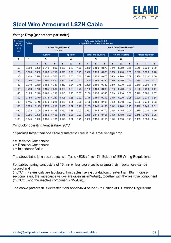
Steel Wire Armoured LSZH CableVoltage Drop (per ampere per metre)
Conductor Cross
Sectional Area
mm²
2 Cables
DC
Reference Method C & F(clipped direct, on tray or in free air)
2 Cables Single Phase ACmV/A/m
3 or 4 Cales Three Phase ACmV/A/m
Touching Spaced* Trefoil and Touching Flat and Touching Flat and Spaced*
1 2 3 4 5 6 7
r x z r x z r x z r x z r x z
50 0.980 0.990 0.210 1.000 0.980 0.29 1.00 0.860 0.180 0.870 0.840 0.250 0.88 0.840 0.330 0.90
70 0.670 0.680 0.200 0.710 0.690 0.29 0.75 0.590 0.170 0.620 0.600 0.250 0.65 0.620 0.320 0.70
95 0.490 0.510 0.195 0.550 0.530 0.28 0.60 0.440 0.170 0.470 0.460 0.240 0.52 0.490 0.310 0.58
120 0.390 0.410 0.190 0.450 0.430 0.27 0.51 0.350 0.165 0.390 0.380 0.240 0.44 0.410 0.300 0.51
150 0.310 0.330 0.185 0.380 0.360 0.27 0.45 0.290 0.160 0.330 0.310 0.230 0.39 0.340 0.290 0.45
185 0.250 0.270 0.185 0.330 0.300 0.26 0.40 0.230 0.160 0.280 0.260 0.230 0.34 0.290 0.290 0.41
240 0.195 0.210 0.180 0.280 0.240 0.26 0.35 0.180 0.155 0.240 0.210 0.220 0.30 0.240 0.280 0.37
300 0.155 0.170 0.175 0.250 0.195 0.25 0.32 0.145 0.150 0.210 0.170 0.220 0.28 0.200 0.270 0.34
400 0.115 0.145 0.170 0.220 0.180 0.24 0.30 0.125 0.150 0.195 0.160 0.210 0.27 0.200 0.270 0.33
500 0.093 0.125 0.170 0.210 0.165 0.24 0.29 0.105 0.145 0.180 0.145 0.200 0.25 0.190 0.240 0.31
630 0.073 0.105 0.165 0.195 0.150 0.23 0.27 0.092 0.145 0.170 0.135 0.195 0.24 0.175 0.230 0.29
800 0.056 0.090 0.160 0.190 0.145 0.23 0.27 0.086 0.140 0.165 0.130 0.180 0.23 0.175 0.195 0.26
1000 0.045 0.092 0.155 0.180 0.140 0.21 0.25 0.080 0.135 0.155 0.125 0.170 0.21 0.165 0.180 0.24
Conductor operating temperature: 90ºC
* Spacings larger than one cable diameter will result in a larger voltage drop.
r = Resistive Componentx = Reactive Componentz = Impedance Value
The above table is in accordance with Table 4E3B of the 17th Edition of IEE Wiring Regulations.
For cables having conductors of 16mm² or less cross-sectional area their inductances can be ignored and (mV/A/m)r values only are tabulated. For cables having conductors greater than 16mm² cross-sectional area, the impedance values are given as (mV/A/m)z, together with the resistive component (mV/A/m)r and the reactive component (mV/A/m)x.
The above paragraph is extracted from Appendix 4 of the 17th Edition of IEE Wiring Regulations.

For more information Tel +44 (0)1270 847 300 Fax +44 (0)1270 847 69232
Steel Wire Armoured LSZH Cable
Current Carrying Capacity (amperes)
Conductor Cross
Sectional Areamm²
Reference Method C(clipped direct)
Amps
Reference Method E(in free air or on a
perforated cable tray, horizontal or vertical)
Amps
Reference Method D(direct in ground or in
ducting in ground, in or around buildings)
Amps
1 Two Core Cable Single Phase
AC or DC
1 Three or 1 Four Core Cable Three
Phase AC
1 Two Core Cable Single Phase
AC or DC
1 Three or 1 Four Core Cable Three
Phase AC
1 Two Core Cable Single Phase
AC or DC
1 Three or 1 Four Core Cable Three
Phase AC
1 2 3 4 5 6 7
1.5 27 23 29 25 25 21
2.5 36 31 39 33 33 28
4.0 49 42 52 44 43 36
6.0 62 53 66 56 53 44
10.0 85 73 90 78 71 58
16.0 110 94 115 99 91 75
25.0 146 124 152 131 116 96
35.0 180 154 188 162 139 115
50.0 219 187 228 197 164 135
70.0 279 238 291 251 203 167
95.0 338 289 354 304 239 197
120.0 392 335 410 353 271 223
150.0 451 386 472 406 306 251
185.0 515 441 539 463 343 281
240.0 607 520 636 546 395 324
300.0 698 599 732 628 446 365
400.0 787 673 847 728 - -
Air ambient temperature: 30°CGround ambient temperature: 20°CConductor operating temperature: 90°C
1. Where a conductor operates at a temperature exceeding 70°C, it must be ascertained that the equipment connected to the conductor is suitable for the conductor operating temperature (see Regulation 512.1.2).
2. Where cables in this table are connected to equipment or accessories designed to operate at a temperature not exceeding 70°C, the current ratings given in the equivalent table for 70°C thermoplastic insulated cables (Table 4D4A) must be used (see Regulation 523.1).
The above table is in accordance with table 4E4A of the 17th Edition of IEE Wiring Regulations.
Electrical Characteristics XLPE/LSZH/AWA/LSZH

[email protected] www.unipartrail.com/elandcables 33
Steel Wire Armoured LSZH CableVoltage Drop (per ampere per metre)
Conductor operating temperature: 90ºC
r = Resistive Componentx = Reactive Componentz = Impedance Value
The above table is in accordance with Table 4E4B of the 17th Edition of IEE Wiring Regulations.
For cables having conductors of 16mm² or less cross-sectional area, their inductances can be ignored and (mV/A/m)r values only are tabulated. For cables having conductors greater than 16mm² cross-sectional area, the impedance values are given as (mV/A/m)z, together with the resistive component (mV/A/m)r and the reactive component (mV/A/m)x.
The above paragraph is extracted from Appendix 4 of the 17th Edition of IEE Wiring Regulations.
Conductor Cross
Sectional Areamm²
Two Core Cable DC
Two Core Cable Single Phase AC
mV/A/m
Three or Four Core Cable Three Phase AC
mV/A/m
1 2 3 4
1.5 31.000 31.0 27.0
2.5 19.000 19.0 16.0
4.0 12.000 12.0 10.0
6.0 7.900 7.9 6.8
10.0 4.700 4.7 4.0
16.0 2.900 2.9 2.5
r x z r x z
25.0 1.850 1.85 0.160 1.900 1.600 0.140 1.650
35.0 1.350 1.35 0.155 1.350 1.150 0.135 1.150
50.0 0.980 0.99 0.155 1.000 0.860 0.135 0.870
70.0 0.670 0.67 0.150 0.069 0.590 0.130 0.600
95.0 0.490 0.50 0.150 0.052 0.430 0.130 0.450
120.0 0.390 0.40 0.145 0.420 0.340 0.130 0.370
150.0 0.310 0.32 0.145 0.350 0.280 0.125 0.300
185.0 0.250 0.26 0.145 0.290 0.220 0.125 0.260
240.0 0.195 0.20 0.140 0.240 0.175 0.125 0.210
300.0 0.155 0.16 0.140 0.210 0.140 0.120 0.185
400.0 0.120 0.13 0.140 0.190 0.115 0.120 0.165

For more information Tel +44 (0)1270 847 300 Fax +44 (0)1270 847 69234
11kV XLPE LSZH Cable
Application
Standards
Conductor
Insulation
Power cables for use in power networks, underground, outdoors and in cable ducting. For installation where fire, smoke emission and toxic fumes create a potential threat to life and equipment.
BS7835
Class 2 stranded plain copper conductor to BS EN 60228:2005 (previously BS6360)
XLPE (Cross-Linked Polyethylene) Type GP8 to BS7655
Conductor Screen Semi-conducting material
Insulation Screen Semi-conducting material
Metallic Screen Individual and overall copper tape screen to BS6622
Filler PETP (Polyethylene Terephthalate) fibres
Separator Binding tape
Bedding LSZH (Low Smoke Zero Halogen)
Armouring Single core: AWA (Aluminium Wire Armour) Multi-core: SWA (Steel Wire Armour)
Sheath
Sheath Colour
LSZH (Low Smoke Zero Halogen)
Red or Black

[email protected] www.unipartrail.com/elandcables 35
Voltage Rating 6350/11000V
Temperature Rating
Combustion Characteristics
Minimum Bending Radius
0°C to +70°C
Oxygen index: 35
Temperature index: 280°C
HCL emission: 0.5% in accordance with BS EN 50267-2-1
Low Smoke classification based on 3 metre cube test.
Completed cables comply with the requirements of fire test BS4066-3 Category 3.
Single Cores: 15 x overall diameterThree Cores: 12 x overall diameter
(Single Cores 12 x overall diameter and 3 cores 10 x overall diameter where bands are positioned adjacent to joint or terminations provided that the bending is carefully controlled by the use of a former.)
11kV XLPE LSZH Cable

For more information Tel +44 (0)1270 847 300 Fax +44 (0)1270 847 69236
11kV XLPE LSZH Cable
DimensionsNo. of Cores x Nominal Cross Sectional Area
# x mm²
Nominal Diametermm
Nominal Weightkg/Km
Under Armour Over Armour Overall
1 x 50 21.7 24.9 28.5 1200
1 x 70 23.0 26.2 30.0 1500
1 x 95 24.7 27.9 31.7 1600
1 x 120 26.7 29.9 33.9 2100
1 x 150 27.5 31.5 35.7 2500
1 x 185 29.3 33.3 37.5 2900
1 x 240 31.6 35.6 40.0 3600
1 x 300 34.6 38.6 43.0 4300
1 x 400 37.0 41.0 45.8 5200
1 x 500 40.5 45.5 50.5 6500
1 x 630 44.6 49.6 54.8 8000
1 x 800 48.8 53.8 59.2 9850
1 x 1000 53.5 58.5 64.3 12100
3 x 25 39.0 44.0 48.8 4300
3 x 35 41.6 46.6 51.6 4700
3 x 50 44.4 49.4 54.6 5300
3 x 70 48.1 53.1 58.5 6300
3 x 95 52.0 57.0 62.6 7300
3 x 120 55.6 60.6 66.6 8400
3 x 150 58.6 63.6 69.8 9600
3 x 185 62.7 67.7 74.1 11000
3 x 240 68.1 74.4 81.2 14000
3 x 300 73.5 79.8 87.0 16600
[email protected] www.unipartrail.com/elandcables 37
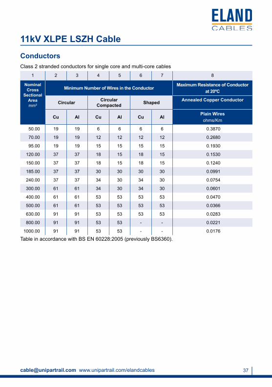
11kV XLPE LSZH Cable
Table in accordance with BS EN 60228:2005 (previously BS6360).
ConductorsClass 2 stranded conductors for single core and multi-core cables
1 2 3 4 5 6 7 8
Nominal Cross
Sectional Areamm²
Minimum Number of Wires in the ConductorMaximum Resistance of Conductor
at 20ºC
Circular Circular Compacted Shaped Annealed Copper Conductor
Cu Al Cu Al Cu AlPlain Wires
ohms/Km
50.00 19 19 6 6 6 6 0.3870
70.00 19 19 12 12 12 12 0.2680
95.00 19 19 15 15 15 15 0.1930
120.00 37 37 18 15 18 15 0.1530
150.00 37 37 18 15 18 15 0.1240
185.00 37 37 30 30 30 30 0.0991
240.00 37 37 34 30 34 30 0.0754
300.00 61 61 34 30 34 30 0.0601
400.00 61 61 53 53 53 53 0.0470
500.00 61 61 53 53 53 53 0.0366
630.00 91 91 53 53 53 53 0.0283
800.00 91 91 53 53 - - 0.0221
1000.00 91 91 53 53 - - 0.0176

For more information Tel +44 (0)1270 847 300 Fax +44 (0)1270 847 69238
11kV XLPE LSZH Cable
Copper Conductor Dimensions and Current Carrying Capacity (amperes)Electrical Characteristics
No. of Cores x Nominal
Cross Sectional
Area
Continuous Current Rating in Ground
Amps
Continuous Current Rating in Ducts
Amps
Continuous Current Rating in AirAmps
# x mm² Trefoil Flat Trefoil Flat Trefoil Flat
1 x 50 220 230 220 220 250 300
1 x 70 270 280 260 270 310 370
1 x 95 320 335 305 325 375 460
1 x 120 360 380 340 370 430 530
1 x 150 410 430 375 410 490 600
1 x 185 455 485 410 460 550 690
1 x 240 520 560 470 540 650 820
1 x 300 580 640 500 610 740 940
1 x 400 650 730 530 690 840 1100
1 x 500 710 830 570 780 930 1280
1 x 630 760 940 620 890 1040 1480
1 x 800 810 1060 660 990 1140 1690
1 x 1000 860 1170 690 1090 1230 1900
3 x 25 140 140 125 125 145 145
3 x 35 170 170 150 150 175 175
3 x 50 210 210 180 180 220 220
3 x 70 250 250 215 215 270 270
3 x 95 300 300 255 255 330 330
3 x 120 340 340 290 290 380 380
3 x 150 380 380 330 330 430 430
3 x 185 430 430 370 370 490 490
3 x 240 500 500 430 430 570 570
3 x 300 540 540 470 470 650 650

[email protected] www.unipartrail.com/elandcables 39
11kV XLPE LSZH Cable
Correction Factors
Air Temperature 25°C 30°C 35°C 40°C 45°C 50°C 55°C
Correction Factor 1.00 0.96 0.92 0.88 0.83 0.78 0.73
Ground Temperature 10°C 15°C 20°C 25°C 30°C 35°C 40°C
Correction Factor 1.03 1.00 0.97 0.93 0.89 0.86 0.82
Ground Thermal
Resistivity0.9 1.0 1.2 1.5 2.0 2.5 3.0
Correction Factor 1.06 1.04 1.00 0.92 0.82 0.74 0.68
Depth of Laying
m0.80 1.00 1.25 1.50 1.75 2.00 2.50
Correction Factor 1.00 0.97 0.95 0.94 0.93 0.91 0.90

For more information Tel +44 (0)1270 847 300 Fax +44 (0)1270 847 69240
11kV XLPE PVC Cable
Application
Standards
Conductor
Insulation
Power cables for for use in power networks, underground and in cable ducting.
BS6622
Class 2 stranded plain copper conductor to BS EN 60228:2005 (previously BS6360)
XLPE (Cross-Linked Polyethylene)Type GP8 to BS7655
Conductor Screen Semi-conducting material
Insulation Screen Semi-conducting material
Metallic Screen Individual and overall copper tape screen to BS6622
Filler PETP (Polyethylene Terephthalate) fibres
Separator Binding tape
Bedding PVC (Polyvinyl Chloride) Type TM1 to BS7655
Armouring Single core: AWA (Aluminium Wire Armour)Multi-core: SWA (Steel Wire Armour)
Sheath PVC (Polyvinyl Chloride) Type TM1 to BS7655
Voltage Rating 6350/11000V
Sheath Colour Red or Black
Temperature Rating 0°C to +70°C

[email protected] www.unipartrail.com/elandcables 41
Minimum Bending Radius
Single Cores: 15 x overall diameterThree Cores: 12 x overall diameter
(Single Cores 12 x overall diameter and 3 cores 10 x overall diameter where bands are positioned adjacent to joint or terminations provided that the bending is carefully controlled by the use of a former.)
11kV XLPE PVC Cable
DimensionsNo. of Cores x Nominal Cross Sectional Area
# x mm²
Nominal Diameter mm
Nominal Weightkg/Km
Under Armour Over Armour Overall
1 x 50 21.7 24.9 28.5 1200
1 x 70 23.0 26.2 30.0 1500
1 x 95 24.7 27.9 31.7 1600
1 x 120 26.7 29.9 33.9 2100
1 x 150 27.5 31.5 35.7 2500
1 x 185 29.3 33.3 37.5 2900
1 x 240 31.6 35.6 40.0 3600
1 x 300 34.6 38.6 43.0 4300
1 x 400 37.0 41.0 45.8 5200
1 x 500 40.5 45.5 50.5 6500
1 x 630 44.6 49.6 54.8 8000
1 x 800 48.8 53.8 59.2 9850
1 x 1000 53.5 58.5 64.3 12100
3 x 25 39.0 44.0 48.8 4300
3 x 35 41.6 46.6 51.6 4700
3 x 50 44.4 49.4 54.6 5300
3 x 70 48.1 53.1 58.5 6300
3 x 95 52.0 57.0 62.6 7300
3 x 120 55.6 60.6 66.6 8400
3 x 150 58.6 63.6 69.8 9600
3 x 185 62.7 67.7 74.1 11000
3 x 240 68.1 74.4 81.2 14000
3 x 300 73.5 79.8 87.0 16600

For more information Tel +44 (0)1270 847 300 Fax +44 (0)1270 847 69242
11kV XLPE PVC Cable
Table in accordance with BS EN 60228:2005 (previously BS6360).
ConductorsClass 2 stranded conductors for single Core and multi-core cables
1 2 3 4 5 6 7 8
Nominal Cross
Sectional Areamm²
Minimum Number of Wires in the ConductorMaximum Resistance of Conductor
at 20ºC
Circular Circular Compacted Shaped Annealed Copper Conductor
Cu Al Cu Al Cu AlPlain Wires
ohms/Km
50.00 19 19 6 6 6 6 0.3870
70.00 19 19 12 12 12 12 0.2680
95.00 19 19 15 15 15 15 0.1930
120.00 37 37 18 15 18 15 0.1530
150.00 37 37 18 15 18 15 0.1240
185.00 37 37 30 30 30 30 0.0991
240.00 37 37 34 30 34 30 0.0754
300.00 61 61 34 30 34 30 0.0601
400.00 61 61 53 53 53 53 0.0470
500.00 61 61 53 53 53 53 0.0366
630.00 91 91 53 53 53 53 0.0283
800.00 91 91 53 53 - - 0.0221
1000.00 91 91 53 53 - - 0.0176

[email protected] www.unipartrail.com/elandcables 43
11kV XLPE PVC Cable
Copper Conductor Dimensions and Current Carrying Capacity (amperes)Electrical Characteristics
No. of Cores x Nominal
Cross Sectional
Area
Continuous Current Rating in Ground
Amps
Continuous Current Rating in Ducts
Amps
Continuous Current Rating in AirAmps
# x mm² Trefoil Flat Trefoil Flat Trefoil Flat
1 x 50 220 230 220 220 250 300
1 x 70 270 280 260 270 310 370
1 x 95 320 335 305 325 375 460
1 x 120 360 380 340 370 430 530
1 x 150 410 430 375 410 490 600
1 x 185 455 485 410 460 550 690
1 x 240 520 560 470 540 650 820
1 x 300 580 640 500 610 740 940
1 x 400 650 730 530 690 840 1100
1 x 500 710 830 570 780 930 1280
1 x 630 760 940 620 890 1040 1480
1 x 800 810 1060 660 990 1140 1690
1 x 1000 860 1170 690 1090 1230 1900
3 x 25 140 140 125 125 145 145
3 x 35 170 170 150 150 175 175
3 x 50 210 210 180 180 220 220
3 x 70 250 250 215 215 270 270
3 x 95 300 300 255 255 330 330
3 x 120 340 340 290 290 380 380
3 x 150 380 380 330 330 430 430
3 x 185 430 430 370 370 490 490
3 x 240 500 500 430 430 570 570
3 x 300 540 540 470 470 650 650

For more information Tel +44 (0)1270 847 300 Fax +44 (0)1270 847 69244
11kV XLPE PVC Cable
Correction Factors
Air Temperature 25°C 30°C 35°C 40°C 45°C 50°C 55°C
Correction Factor 1.00 0.96 0.92 0.88 0.83 0.78 0.73
Ground Temperature 10°C 15°C 20°C 25°C 30°C 35°C 40°C
Correction Factor 1.03 1.00 0.97 0.93 0.89 0.86 0.82
Ground Thermal
Resistivity0.9 1.0 1.2 1.5 2.0 2.5 3.0
Correction Factor 1.06 1.04 1.00 0.92 0.82 0.74 0.68
Depth of Laying
m0.80 1.00 1.25 1.50 1.75 2.00 2.50
Correction Factor 1.00 0.97 0.95 0.94 0.93 0.91 0.90

[email protected] www.unipartrail.com/elandcables 45
33kV Cable
Application
Standards
Conductor
Insulation
Power cables for use in power networks, underground and in cable ducting.
BS6622
Class 2 stranded plain copper conductor to BS EN 60228:2005 (previously BS6360)
XLPE (Cross-Linked Polyethylene)Type GP8 to BS7655
Conductor Screen Semi-conducting material
Insulation Screen Semi-conducting material
Metallic Screen Individual and overall copper tape screen to BS6622
Filler PETP (Polyethylene Terephthalate) fibres
Separator Binding tape
Bedding PVC (Polyvinyl Chloride) Type TM1 to BS7655
Armouring Single core: AWA (Aluminium Wire Armour)Multi-core: SWA (Steel Wire Armour)
Sheath PVC (Polyvinyl Chloride) Type TM1 to BS7655
Voltage Rating 19000/33000V
Sheath Colour Red or Black

For more information Tel +44 (0)1270 847 300 Fax +44 (0)1270 847 69246
Temperature Rating
Minimum Bending Radius
0°C to +70°C
Single Cores: 15 x overall diameterThree Cores: 12 x overall diameter
(Single cores 12 x overall diameter and 3 cores 10 x overall diameter where bands are positioned adjacent to joint or terminations provided that the bending is carefully controlled by the use of a former.)
33kV Cable
DimensionsNo. of Cores x Nominal Cross Sectional Area
# x mm²
Nominal Diameter mm
Nominal Weightkg/Km
Under Armour Over Armour Overall
1 x 70 32.6 36.6 41.0 2300
1 x 95 34.3 38.3 42.9 2650
1 x 120 35.9 39.9 44.5 3000
1 x 150 37.5 42.5 47.3 3500
1 x 185 39.3 44.3 49.3 4000
1 x 240 41.7 46.7 51.7 4650
1 x 300 44.2 49.2 54.4 5450
1 x 400 47.3 52.3 57.7 6350
1 x 500 50.5 55.5 61.1 7600
1 x 630 54.2 59.2 65.0 9150
1 x 800 60.5 65.5 71.6 11100
1 x 1000 65.0 70.0 76.5 13400
3 x 50 65.1 71.4 78.2 9150
3 x 70 68.8 75.1 82.1 10300
3 x 95 72.6 78.9 86.1 11600
3 x 120 76.3 82.6 90.0 12800
3 x 150 79.3 85.6 93.2 14050
3 x 185 83.4 89.7 97.5 15650
3 x 240 88.8 95.1 103.3 18200
3 x 300 93.9 100.2 108.8 21100
3 x 400 100.8 107.1 116.1 24200

[email protected] www.unipartrail.com/elandcables 47
Conductors
33kV Cable
Copper Conductors (Insulated Armoured Cables to BS6622)Current Carrying Capacity (amperes)
No. of Cores x Nominal
Cross Sectional
Area
Continuous Current Rating in Ground
Amps
Continuous Current Rating in Ducts
Amps
Continuous Current Rating in AirAmps
# x mm² Trefoil Flat Trefoil Flat Trefoil Flat
1 x 70 270 280 260 270 310 370
1 x 95 320 335 305 325 375 460
1 x 120 360 380 340 370 430 530
1 x 150 410 430 375 410 490 600
1 x 185 455 485 410 460 550 690
1 x 240 520 560 470 540 650 820
1 x 300 580 640 500 610 740 940
1 x 400 650 730 530 690 840 1100
1 x 500 710 830 570 780 930 1280
1 x 630 760 940 620 890 1040 1480
1 x 800 810 1060 660 990 1140 1690
1 x 1000 860 1170 690 1090 1230 1900
3 x 50 210 210 180 180 220 220
3 x 70 250 250 215 215 270 270
3 x 95 300 300 255 255 330 330
3 x 120 340 340 290 290 380 380
3 x 150 380 380 330 330 430 430
3 x 185 430 430 370 370 490 490
3 x 240 500 500 430 430 570 570
3 x 300 540 540 470 470 650 650
3 x 400 600 600 530 530 740 740

For more information Tel +44 (0)1270 847 300 Fax +44 (0)1270 847 69248
Correction Factors
Air Temperature 25°C 30°C 35°C 40°C 45°C 50°C 55°C
Correction Factor 1.00 0.96 0.92 0.88 0.83 0.78 0.73
Ground Temperature 10°C 15°C 20°C 25°C 30°C 35°C 40°C
Correction Factor 1.03 1.00 0.97 0.93 0.89 0.86 0.82
Ground Thermal Resistivity 0.9 1.0 1.2 1.5 2.0 2.5 3.0
Correction Factor 1.06 1.04 1.00 0.92 0.82 0.74 0.68
Depth of Layingm 0.80 1.00 1.25 1.50 1.75 2.00 2.50
Correction Factor 1.00 0.97 0.95 0.94 0.93 0.91 0.90
Class 2 stranded conductors for single Core and multi-core cablesConductors
1 2 3 4 5 6 7 8
Nominal Cross
Sectional Areamm²
Minimum Number of Wires in the ConductorMaximum Resistance of Conductor
at 20ºC
Circular Circular Compacted Shaped Plain Annealed Copper
Conductor
Cu Al Cu Al Cu AlPlain Wires
ohms/Km
70.00 19 19 12 12 12 12 0.2680
95.00 19 19 15 15 15 15 0.1930
120.00 37 37 18 15 18 15 0.1530
150.00 37 37 18 15 18 15 0.1240
185.00 37 37 30 30 30 30 0.0991
240.00 37 37 34 30 34 30 0.0754
300.00 61 61 34 30 34 30 0.0601
400.00 61 61 53 53 53 53 0.0470
33kV Cable
Table in accordance with BS EN 60228:2005 (previously BS6360).

[email protected] www.unipartrail.com/elandcables 49
Aluminium Power Cable
Application
Standards
Conductor
Insulation
Separator
Sheath
Sheath Colour
Voltage Rating
BR880 solid sector-shaped conductors for trackside signalling power supplies.
BR880, BS5467, BS6346
Sector shaped solid aluminium
XLPE (Cross-Linked Polyethylene) Type GP8 to BS7655 or PVC (Polyvinyl Chloride) Type TI 1 to BS7655
PETP (Polyethylene Terephthalate)
PVC (Polyvinyl Chloride) Type 9 to BS7655
Black
600/1000V
Limited Use
Temperature Rating
Core Identification
Distribution of signalling power only. (Not suitable for general signalling use.)
+70˚C (BS6346) or +90˚C (BS5467)
2 Cores: Red, Black4 Cores: Red, Yellow, Blue, Black
Effective 31 March 20062 Cores: Brown, Blue4 Cores: Blue, Brown, Black, Grey

For more information Tel +44 (0)1270 847 300 Fax +44 (0)1270 847 69250
Dimensions
Aluminium Power Cable
Rail Catalogue Number
No. of Cores x Nominal
Conductor Area # x mm²
Nominal Thickness of
Insulation mm
Nominal Thickness of
Sheathmm
Nominal Overall Diameter
mm
Nominal Weightkg/Km
006/142419 2 x 16 1.0 1.8 14.3 420
006/142519 2 x 25 1.2 1.8 16.6 455
006/142609 2 x 35 1.2 1.8 18.0 525
006/142629 2 x 50 1.4 1.8 20.4 620
006/142639 2 x 70 1.4 1.9 22.8 840
006/142644 2 x 95 1.6 2.0 26.2 1020
006/151469 4 x 70 1.4 2.0 30.6 1750
- 4 x 95 1.6 2.2 35.5 2100
ConductorsClass 1 solid conductors for single core and multi-core cables
1 4
Nominal Cross Sectional Areamm²
Maximum Resistance of Conductor at 20˚C
Aluminium and Aluminium Alloy Conductors, Circular or Shaped
ohms/Km
16.00 1.9100
25.00 1.2000
35.00 0.8680
50.00 0.6410
70.00 0.4430
95.00 0.3200
Table in accordance with BS EN 60228:2005 (previously BS6360).
c
a
a
a
d
a Aluminium conductors 10mm² to 35mm² circular only; (see 5.1.1 c). See note to 5.1.2c For single core cables, four sectoral shaped conductors may be assembled into a single
circular conductor. d The maximum resistance of the assembled conductor shall be 25% of that of the individual
component conductors.

[email protected] www.unipartrail.com/elandcables 51
MV Power Cable
Application
Standards
Conductor
Conductor Screen
Insulation
Insulation Screen
Separator
Screen
Cable used to distribute three phase a.c. electrical power supplies at nominal system voltages of 33kV to traction substations on D.C. electrified lines.
NR/PS/ELP/00008 (formerly RT/E/PS/00008) BS6622, BS6234, BS7454, IEC 60502-2, IEC60840
185mm²: Class 1 circular solid aluminium to BS EN 60228:2005 (previously BS6360)300mm²:Class 2 compact circular stranded plain copper to BS EN 60228:2005 (previously BS6360)
Extruded semi-conducting XLPE (Cross-Linked Polyethylene), solidly bonded
XLPE (Cross-Linked Polyethylene)
Extruded semi-conducting XLPE (Cross-Linked Polyethylene), solidly bonded, strippable
Water swellable semi-conducting tape
Copper wire screen, helically wound with equalising copper tape
Separator
Sheath
Sheath Colour
Water swellable tape
MDPE (Medium Density Polyethylene) Type TS2 (Graphite Coated)
Black
Voltage Rating 19000/33000V

For more information Tel +44 (0)1270 847 300 Fax +44 (0)1270 847 69252
MV Power CableTemperature Rating +90˚C
Minimum Bending Radius
15 x overall diameter (12 x overall diameter adjacent to joints or terminations provided that bending is carefully controlled by use of former.)
DimensionsRail Catalogue
NumberNo. of Cores x Nominal
Cross Sectional
Area # x mm²
Nominal Thickness of Conductor
Screen mm
Nominal Thickness of
Insulationmm
Nominal Thickness
of Insulation Screen
mm
Nominal Overall
Diametermm
Nominal Weightkg?Km
006/122514 1 x 185 0.9 8.0 0.6 45.0 2200
006/122511 1 x 300 0.9 8.0 0.6 50.0 4500
ConductorsClass 1 solid conductors for single core and multi-core cables
1 4
Nominal Cross Sectional Areamm²
Maximum Resistance of the Conductor at 20˚C
Aluminium Conductors, Circularohms/Km
185.00 0.1640
Class 2 stranded conductors for single core and multi-core cables1 4 5 8
Nominal Cross
Sectional Areamm²
Minimum Number of Wires in the Conductor
Maximum Resistance of Conductor at 20ºC
Circular Compacted Annealed Copper Conductor
Cu AlPlain Wires
ohms/Km
300.00 34 30 0.0601
Table in accordance with BS EN 60228:2005 (previously BS6360).
Table in accordance with BS EN 60228:2005 (previously BS6360).

[email protected] www.unipartrail.com/elandcables 53
MV Power Cable
Electrical CharacteristicsNominal Cross
Sectional Area
Continuous Current Rating in Ground
Amps
Continuous Current Rating in Air
Amps
CapacitanceµF/km
InductancemH/km
Short Circuit Rating for 1 sec
Kilo Amps
mm² Trefoil Flat Trefoil Flat Trefoil Flat Conductor Screen
185 385 390 435 470 0.205 0.40 0.56 17.1 11.0
300 640 630 730 780 0.243 0.37 0.53 43.2 11.0
Permitted current rating of cables is calculated according to IEC 287, considering the following data:
Ground Laying Depth 0.7m
Specific Resistance of Ground 1°km/W
Ground Temperature 15°C
Ambient Temperature in Free Air 25°C
Maximum Conductor Temperature 90°C
Conductor Temperature of Short Circuit Current 250°C
Screen Temperature of Short Circuit Current 350°C

For more information Tel +44 (0)1270 847 300 Fax +44 (0)1270 847 69254
Trackfeeder Cable
Application
Standards
Conductor
Separator
Sheath
Sheath Colour
Voltage Rating
Temperature Rating
Provides the 650/750 volt D.C. supply from traction substations and track paralleling huts to conductor rails, negative cable connections and where appropriate, bonding.
NR/PS/ELP/21101(formerly RT/E/S/21101)
Class 2 stranded aluminium or tinned copper to BS EN 60228:2005 (previously BS6360)
PETP (Polyethylene Terephthalate)
CSP (Chlorosulphonated Polyethylene) Type RS4 to BS6899
Black
650/750V
-25°C to +85°C
Minimum Bending Radius
Aluminium conductor: 10 x overall diameterCopper conductor: 8 x overall diameter

[email protected] www.unipartrail.com/elandcables 55
Dimensions
Rail Catalogue Number
Nominal Cross
Sectional Area mm²
Conductor Material
No. and Nominal
Diameter of Strands# / mm
Nominal Diameter of Conductor
mm
Nominal Overall
Diametermm
Assigned Continuous
Current RatingAmps
006/116610 1000 Aluminium 127/3.20 41.6 53.0 1500
006/116612 630 Copper 127/2.52 32.8 44.2 1500
006/132840 500 Aluminium 61/3.20 28.8 40.2 800
Trackfeeder Cable
Positive Track Cables
Rail Catalogue Number
Nominal Cross
Sectional Area mm²
Conductor Material
No. and Nominal
Diameter of Strands# / mm
Nominal Diameter of Conductor
mm
Nominal Overall
Diametermm
Assigned Continuous
Current RatingAmps
006/132991 800 Aluminium 127/2.85 37.1 48.5 1200
006/132990 240 Aluminium 61/2.25 20.3 28.3 550
006/132340 161 Copper 91/1.53 16.8 24.8 550
006/116601 150 Aluminium 37/2.25 15.8 19.4 430
Negative Track Cables

For more information Tel +44 (0)1270 847 300 Fax +44 (0)1270 847 69256
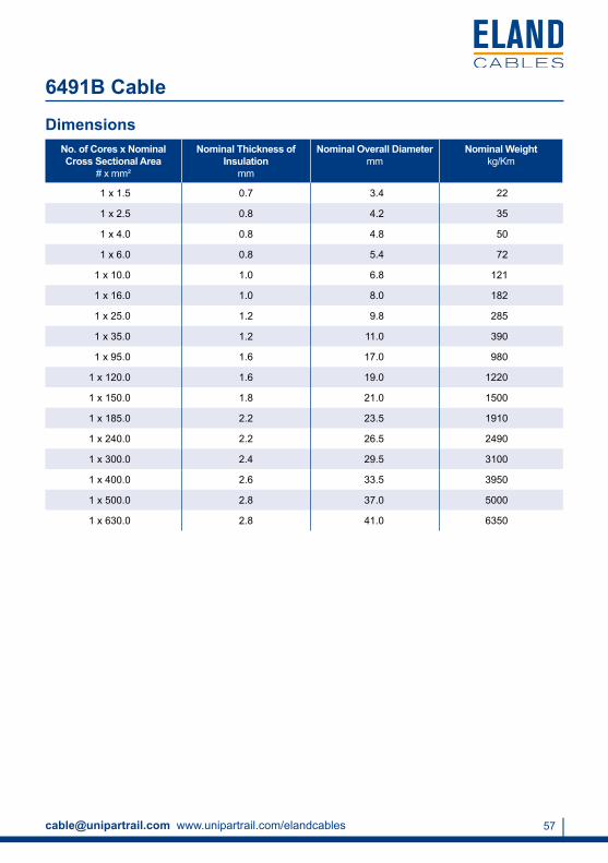
6491B Cable
Application
Standards
Conductor
Insulation
Insulation Colour
Voltage Rating
Suitable for use in conduit and for fixed, protected installation. For installation where fire, smoke emission and toxic fumes create a potential threat to life and equipment.
BS7211
Class 2 stranded plain copper conductors to BS EN 60228:2005 (previously BS6360)
LSZH (Low Smoke Zero Halogen)
Black, Blue, Green/Yellow, Red, Yellow, White, Violet, Brown, Grey, Orange, Pink
450/750V
Temperature Rating
Minimum Bending Radius
0°C to +90°C
Up to 10mm²: 3 x overall diameter
10mm² to 25mm²: 4 x overall diameter
Above 25mm²: 5 x overall diameter
[email protected] www.unipartrail.com/elandcables 57
6491B Cable
DimensionsNo. of Cores x Nominal Cross Sectional Area
# x mm²
Nominal Thickness of Insulation
mm
Nominal Overall Diameter mm
Nominal Weightkg/Km
1 x 1.5 0.7 3.4 22
1 x 2.5 0.8 4.2 35
1 x 4.0 0.8 4.8 50
1 x 6.0 0.8 5.4 72
1 x 10.0 1.0 6.8 121
1 x 16.0 1.0 8.0 182
1 x 25.0 1.2 9.8 285
1 x 35.0 1.2 11.0 390
1 x 95.0 1.6 17.0 980
1 x 120.0 1.6 19.0 1220
1 x 150.0 1.8 21.0 1500
1 x 185.0 2.2 23.5 1910
1 x 240.0 2.2 26.5 2490
1 x 300.0 2.4 29.5 3100
1 x 400.0 2.6 33.5 3950
1 x 500.0 2.8 37.0 5000
1 x 630.0 2.8 41.0 6350
For more information Tel +44 (0)1270 847 300 Fax +44 (0)1270 847 69258
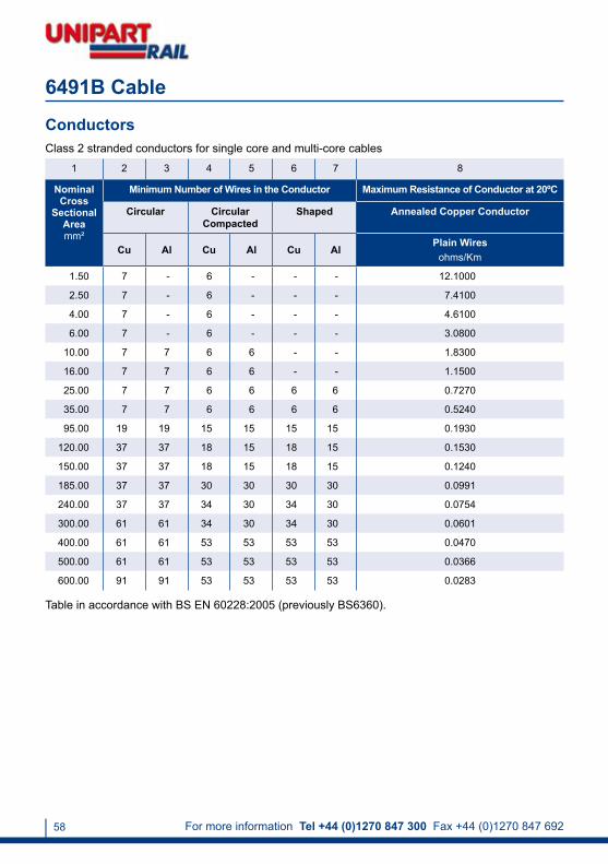
ConductorsClass 2 stranded conductors for single core and multi-core cables
1 2 3 4 5 6 7 8
Nominal Cross
Sectional Areamm²
Minimum Number of Wires in the Conductor Maximum Resistance of Conductor at 20ºC
Circular Circular Compacted
Shaped Annealed Copper Conductor
Cu Al Cu Al Cu AlPlain Wires
ohms/Km
1.50 7 - 6 - - - 12.1000
2.50 7 - 6 - - - 7.4100
4.00 7 - 6 - - - 4.6100
6.00 7 - 6 - - - 3.0800
10.00 7 7 6 6 - - 1.8300
16.00 7 7 6 6 - - 1.1500
25.00 7 7 6 6 6 6 0.7270
35.00 7 7 6 6 6 6 0.5240
95.00 19 19 15 15 15 15 0.1930
120.00 37 37 18 15 18 15 0.1530
150.00 37 37 18 15 18 15 0.1240
185.00 37 37 30 30 30 30 0.0991
240.00 37 37 34 30 34 30 0.0754
300.00 61 61 34 30 34 30 0.0601
400.00 61 61 53 53 53 53 0.0470
500.00 61 61 53 53 53 53 0.0366
600.00 91 91 53 53 53 53 0.0283
Table in accordance with BS EN 60228:2005 (previously BS6360).
6491B Cable

[email protected] www.unipartrail.com/elandcables 59
6491B Cable
Nominal Cross
Sectional Areamm²
Reference Method 4 (enclosed in conduit
in thermally insulating wall etc)
Reference Method 3(enclosed in conduit
on a wall or in trunking etc.)
Reference Method 1(clipped direct)
Reference Method 11(on a perforated cable
tray horizontal or vertical)
Reference Method 12 (free air)
Horizontal Flat
Spaced
Vertical Flat
Spaced
Trefoil
2 Cables Single Phase AC or
DCAmps
3 or 4 Cables Three Phase
AC Amps
2 Cables Single Phase AC or
DC Amps
3 or 4 Cables Three Phase
AC Amps
2 Cables Single Phase
AC or DC Flat and
TouchingAmps
3 or 4 Cables Three
Phase AC Flat and
Touching or Trefoil
Amps
2 Cables Single Phase
AC or DC Flat and
TouchingAmps
3 or 4 Cables Three
Phase AC Flat and
Touching or Trefoil
Amps
2 Cables Single
Phase AC or DC or 3 Cables
Three Phase
ACAmps
2 Cables Single
Phase AC or DC or 3 Cables
Three Phase AC
Amps
3 Cables Three Phase
ACAmps
1 2 3 4 5 6 7 8 9 10 11 12
1.0 14 13 17 15 19 17.5 - - - - -
1.5 18 17 22 19 25 23.0 - - - - -
2.5 24 23 30 26 34 31.0 - - - - -
4.0 33 30 40 35 46 41.0 - - - - -
6.0 43 39 51 45 59 54.0 - - - - -
10.0 58 53 71 63 81 74.0 - - - - -
16.0 76 70 95 85 109 99.0 - - - - -
25.0 100 91 126 111 143 130.0 158 140 183 163 138
35.0 124 111 156 138 176 161.0 195 176 226 203 171
50.0 149 135 189 168 228 209.0 293 215 274 246 209
70.0 189 170 240 214 293 268.0 308 279 351 318 270
95.0 228 205 290 259 355 326.0 375 341 426 389 330
120.0 263 235 336 299 413 379.0 436 398 495 453 385
150.0 300 270 375 328 476 436.0 505 461 570 524 445
185.0 341 306 426 370 545 500.0 579 530 651 600 511
240.0 400 358 500 433 644 590.0 686 630 769 711 606
300.0 459 410 573 493 743 681.0 794 730 886 824 701
400.0 - - 683 584 868 793.0 915 849 1065 994 820
500.0 - - 783 666 990 904.0 1044 973 1228 1150 936
630.0 - - 900 764 1130 1033.0 1191 1115 1423 1338 1069
800.0 - - - - 1288 1179.0 1358 1275 1581 1485 1214
1000.0 - - - - 1443 1323.0 1520 1436 1775 1671 1349
Electrical CharacteristicsCurrent Carrying Capacity (amperes)
Ambient temperature: 30°CConductor operating temperature: 90°C

For more information Tel +44 (0)1270 847 300 Fax +44 (0)1270 847 69260
Voltage Drop (per ampere per metre)Nominal Cross -
SectionalAreamm²
2 Cables, Single Phase AC
2 Cables DC
mV/A/m
Reference Methods 3 & 4
(enclosed in conduit etc, in or on a wall)
mV/A/m
Reference Methods 1 & 11
(clipped direct or on trays, touching)
mV/A/m
Reference Method 12 (spaced*)mV/A/m
1 2 3 4 5
1.0 46.0 46.0 46.0 46.0
1.5 31.0 31.0 31.0 31.0
2.5 19.0 19.0 19.0 19.0
4.0 12.0 12.0 12.0 12.0
6.0 7.9 7.9 7.9 7.9
10.0 4.7 4.7 4.7 4.7
16.0 2.9 2.9 2.9 2.9
r x z r x z r x z
25.0 1.850 1.850 0.31 1.90 1.850 0.190 1.850 1.850 0.28 1.85
35.0 1.350 1.350 0.29 1.35 1.350 0.180 1.350 1.350 0.27 1.35
50.0 0.990 1.000 0.29 1.05 0.990 0.180 1.000 0.990 0.27 1.00
70.0 0.680 0.700 0.28 0.75 0.680 0.175 0.710 0.680 0.26 0.73
95.0 0.490 0.510 0.27 0.58 0.490 0.170 0.520 0.490 0.26 0.56
120.0 0.390 0.410 0.26 0.48 0.390 0.165 0.430 0.390 0.25 0.47
150.0 0.320 0.330 0.26 0.43 0.320 0.165 0.360 0.320 0.25 0.41
185.0 0.250 0.270 0.26 0.37 0.260 0.165 0.300 0.250 0.25 0.36
240.0 0.190 0.210 0.26 0.33 0.200 0.160 0.250 0.195 0.25 0.31
300.0 0.155 0.175 0.25 0.31 0.160 0.160 0.220 0.155 0.25 0.29
400.0 0.120 0.140 0.25 0.29 0.130 0.155 0.200 0.125 0.24 0.27
500.0 0.093 0.120 0.25 0.28 0.105 0.155 0.185 0.098 0.24 0.26
630.0 0.072 0.100 0.25 0.27 0.086 0.155 0.175 0.078 0.24 0.25
800.0 0.056 - 0.072 0.150 0.170 0.640 0.24 0.25
1000.0 0.045 - 0.063 0.150 0.165 0.054 0.24 0.24
6491B Cable
Conductor operating temperature: 90°C
r = Resistive Componentx = Reactive Componentz = Impedance Value
Notes1. Where the conductor is to be protected by a semi-enclosed fuse to BS3036, see item 6.2 of the preface to appendix 4 within 16th edition regs.
2. The current-carrying capacities in columns 2 to 5 are also applicable to flexible cables BS7211 table 3(b) where the cables are used in fixed installations.

[email protected] www.unipartrail.com/elandcables 61
Voltage Drop (per ampere per metre)3 or 4 Cables, Three Phase AC
Reference Methods 3 & 4 (enclosed in conduit etc,
in or on a wall)mV/A/m
Reference Methods 1, 11 & 12(in trefoil)mV/A/m
Reference Method (flat and touching)
mV/A/m
Reference Methods 12(flat spaced*)
mV/A/m
6 7 8 9
40.0 40.0 40.0 40.0
27.0 27.0 27.0 27.0
16.0 16.0 16.0 16.0
10.0 10.0 10.0 10.0
6.8 6.8 6.8 6.8
4.0 4.0 4.0 4.0
2.5 2.5 2.5 2.5
r x z r x z r x z r x z
1.600 0.27 1.650 1.600 0.165 1.60 1.600 0.190 1.600 1.600 0.27 1.65
1.150 0.25 1.150 1.150 0.155 1.15 1.150 0.180 1.150 1.150 0.26 1.20
0.870 0.25 0.900 0.860 0.155 0.87 0.860 0.180 0.870 0.860 0.26 0.89
0.600 0.24 0.650 0.590 0.150 0.61 0.590 0.175 0.620 0.590 0.25 0.65
0.440 0.23 0.500 0.430 0.145 0.45 0.430 0.170 0.460 0.430 0.25 0.49
0.350 0.23 0.420 0.340 0.140 0.37 0.340 0.165 0.380 0.340 0.24 0.42
0.290 0.23 0.370 0.280 0.140 0.31 0.280 0.165 0.320 0.280 0.24 0.37
0.230 0.23 0.320 0.220 0.140 0.26 0.220 0.165 0.280 0.220 0.24 0.33
0.190 0.22 0.290 0.170 0.140 0.22 0.170 0.165 0.240 0.170 0.24 0.29
0.150 0.22 0.270 0.140 0.140 0.20 0.135 0.160 0.210 0.135 0.24 0.27
0.130 0.22 0.250 0.110 0.135 0.18 0.110 0.160 0.195 0.110 0.24 0.26
0.100 0.22 0.240 0.090 0.135 0.16 0.088 0.160 0.180 0.085 0.24 0.25
0.090 0.21 0.230 0.074 0.135 0.15 0.171 0.160 0.170 0.068 0.23 0.24
- 0.062 0.130 0.15 0.059 0.155 0.165 0.055 0.23 0.24
- 0.055 0.130 0.14 0.050 0.155 0.165 0.047 0.23 0.24
6491B Cable
3. For cable in rigid PVC conduit the values stated in table 4D1 are applicable (see Regulation 512-02).
4. Where a conductor operates at a temperature exceeding 70°C, it shall be ascertained that the equipment connected to the conductor is suitable for the conductor operating temperature (see Regulation 512-02).
5. Where cables in this table are connected to equipment or accessories designed to operate at a temperature not exceeding 70°C, the current ratings given in the equivalent table for 70°C PVC insulated cables BS6004, BS6346 shall be used (see Reg 523-01-01).
* Spacings larger than those specified in Method 12 (see table 4A 16th edition regs) will result in larger volt drop.

For more information Tel +44 (0)1270 847 300 Fax +44 (0)1270 847 69262
6491X Cable
Application
Standards
Conductor
Insulation
Insulation Colour
Voltage Rating
For use in conduit and fixed, protected installation in switchgear, lighting and appliances.
BS6004
H07V-R: Class 2 stranded plain copper conductors to BS EN 60228:2005 (previously BS6360)
H07V-U: Class 1 solid plain copper conductor to BS EN 60228:2005 (previously BS6360)
PVC (Polyvinyl Chloride) Type TI1 to BS7655
Red, Black, Blue, Yellow, Brown, White, Green/Yellow, Grey
450/750V
Temperature Rating
Minimum Bending Radius
0°C to +70°C
Up to 10mm²: 3 x overall diameter
10mm² to 25mm²: 4 x overall diameter
Above 25mm²: 5 x overall diameter
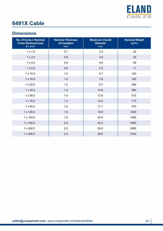
[email protected] www.unipartrail.com/elandcables 63
DimensionsNo. of Cores x Nominal Cross Sectional Area
# x mm²
Nominal Thickness of Insulation
mm
Maximum Overall Diameter
mm
Nominal Weightkg/Km
1 x 1.5 0.7 3.3 22
1 x 2.5 0.8 3.9 32
1 x 4.0 0.8 4.6 50
1 x 6.0 0.8 5.2 71
1 x 10.0 1.0 6.7 120
1 x 16.0 1.0 7.8 180
1 x 25.0 1.2 9.7 280
1 x 35.0 1.2 10.9 380
1 x 50.0 1.4 12.8 510
1 x 70.0 1.4 14.6 710
1 x 95.0 1.6 17.1 970
1 x 120.0 1.6 18.8 1200
1 x 150.0 1.8 20.9 1480
1 x 185.0 2.0 23.3 1900
1 x 240.0 2.2 26.6 2480
1 x 300.0 2.4 29.6 3100
6491X Cable

For more information Tel +44 (0)1270 847 300 Fax +44 (0)1270 847 69264
ConductorsClass 2 stranded conductors for single core and multi-core cables
1 2 3 4 5 6 7 8
Nominal Cross
Sectional Areamm²
Minimum Number of Wires in the Conductor Maximum Resistance of Conductor at 20ºC
Circular Circular Compacted
Shaped Annealed Copper Conductor
Cu Al Cu Al Cu AlPlain Wires
ohms/Km
1.00 7 - - - - - 18.1000
1.50 7 - 6 - - - 12.1000
2.50 7 - 6 - - - 7.4100
4.00 7 - 6 - - - 4.6100
6.00 7 - 6 - - - 3.0800
10.00 7 7 6 6 - - 1.8300
16.00 7 7 6 6 - - 1.1500
25.00 7 7 6 6 6 6 0.7270
35.00 7 7 6 6 6 6 0.5240
50.00 19 19 6 6 6 6 0.3870
70.00 19 19 12 12 12 12 0.2680
95.00 19 19 15 15 15 15 0.1930
120.00 37 37 18 15 18 15 0.1530
150.00 37 37 18 15 18 15 0.1240
185.00 37 37 30 30 30 30 0.0991
240.00 37 37 34 30 34 30 0.0754
300.00 61 61 34 30 34 30 0.0601
630.00 91 91 53 53 53 53 0.0283
Table in accordance with BS EN 60228:2005 (previously BS6360).
6491X Cable

[email protected] www.unipartrail.com/elandcables 65
Conductor Cross
Sectional Areamm²
Reference Method A (enclosed in conduit
in thermally insulating wall etc.)
Amps
Reference Method B(enclosed in conduit
on a wall or in a trunking etc.)
Amps
Reference Method C
(clipped direct)Amps
Reference Method F(in free air or on a perforated cable tray etc.
horizontal or vertical)Amps
Touching Spaced by one Diameter
2 Cables Single Phase AC or
DC
3 or 4 Cables Three Phase
AC
2 Cables Single Phase AC or
DC
3 or 4 Cables Three Phase
AC
2 Cables Single Phase
AC or DC Flat or
Touching
3 or 4 Cables Three Phase
AC Flat & Touching or Trefoil
2 Cables Single Phase
AC or DC Flat
3 Cables Three
Phase AC Flat
3 Cables Three
Phase AC Trefoil
2 Cables Single Phase AC or DC or 3 Cables Three Phase AC Flat
Horizontal Vertical
1 2 3 4 5 6 7 8 9 10 11 12
1.0 11.0 10.5 13.5 12.0 15.5 14.0 - - - - -
1.5 14.5 13.5 17.5 15.5 20.0 18.0 - - - - -
2.5 20.0 18.0 24.0 21.0 27.0 25.0 - - - - -
4.0 26.0 24.0 32.0 28.0 37.0 33.0 - - - - -
6.0 34.0 31.0 41.0 36.0 47.0 43.0 - - - - -
10.0 46.0 42.0 57.0 50.0 65.0 59.0 - - - - -
16.0 61.0 56.0 76.0 68.0 87.0 79.0 - - - - -
25.0 80.0 73.0 101.0 89.0 114.0 104.0 131 114 110 146 130
35.0 99.0 89.0 125.0 110.0 141.0 129.0 162 143 137 181 162
50.0 119.0 108.0 151.0 134.0 182.0 167.0 196 174 167 219 197
70.0 151.0 136.0 192.0 171.0 234.0 214.0 251 225 216 281 254
95.0 182.0 164.0 232.0 207.0 284.0 261.0 304 275 264 341 311
120.0 210.0 188.0 269.0 239.0 330.0 303.0 352 321 308 396 362
150.0 240.0 216.0 300.0 262.0 381.0 349.0 406 372 356 456 419
185.0 273.0 245.0 341.0 296.0 436.0 400.0 463 427 409 521 480
240.0 321.0 286.0 400.0 346.0 515.0 472.0 546 507 485 615 569
300.0 367.0 328.0 458.0 394.0 594.0 545.0 629 587 561 709 659
400.0 - - 546.0 467.0 694.0 634.0 754 589 656 852 795
500.0 - - 626.0 533.0 792.0 723.0 868 789 749 982 920
630.0 - - 720.0 611.0 904.0 826.0 1005 905 855 1138 1070
Current Carrying Capacity (amperes)
Ambient temperature: 30°CConductor operating temperature: 70°C
The above table is in accordance with Table 4D1A of the 17th Edition of IEE Wiring Regulations.
6491X Cable
Electrical Characteristics

For more information Tel +44 (0)1270 847 300 Fax +44 (0)1270 847 69266
Voltage Drop (per ampere per metre)Conductor
Cross Sectional
Area mm²
2 Cables DC
mV/A/m
2 Cables, Single Phase AC mV/A/m
Reference Methods A & B
(enclosed in conduit or trunking)
Reference Methods C, F, & G(clipped direct, on tray or in free air)
Cable Touching Cable Spaced*
1 2 3 4 5
1.0 44.000 44.0 44.0 44.0
1.5 29.000 29.0 29.0 29.0
2.5 18.000 18.0 18.0 18.0
4.0 11.000 11.0 11.0 11.0
6.0 7.300 7.3 7.3 7.3
10.0 4.400 4.4 4.4 4.4
16.0 2.800 2.8 2.8 2.8
r x z r x z r x z
25.0 1.750 1.800 0.33 1.80 1.750 0.200 1.750 1.750 0.29 1.80
35.0 1.250 1.300 0.31 1.30 1.250 0.195 1.250 1.250 0.28 1.30
50.0 0.930 0.950 0.30 1.00 0.930 0.190 0.950 0.930 0.28 0.97
70.0 0.630 0.650 0.29 0.72 0.630 0.185 0.660 0.630 0.27 0.69
95.0 0.460 0.490 0.28 0.56 0.470 0.180 0.500 0.470 0.27 0.54
120.0 0.360 0.390 0.27 0.47 0.370 0.175 0.410 0.370 0.26 0.45
150.0 0.290 0.310 0.27 0.41 0.300 0.175 0.340 0.290 0.26 0.39
185.0 0.230 0.250 0.27 0.37 0.240 0.170 0.290 0.240 0.26 0.35
240.0 0.180 0.195 0.26 0.33 0.185 0.165 0.250 0.185 0.25 0.31
300.0 0.145 0.160 0.26 0.31 0.150 0.165 0.220 0.150 0.25 0.29
400.0 0.105 0.130 0.26 0.29 0.120 0.160 0.200 0.115 0.25 0.27
500.0 0.086 0.110 0.26 0.28 0.098 0.155 0.185 0.093 0.24 0.26
630.0 0.068 0.094 0.25 0.27 0.081 0.155 0.175 0.076 0.24 0.25
6491X Cable

[email protected] www.unipartrail.com/elandcables 67
6491X CableVoltage Drop (per ampere per metre)
r = Resistive Componentx = Reactive Componentz = Impedance Value
Conductor operating temperature: 70°C
* Spacings larger than one cable diameter will result in a larger voltage drop.
The above table is in accordance with Table 4D1B of the 17th Edition of IEE Wiring Regulations.
For cables having conductors of 16mm² or less cross-sectional area, their inductances can be ignored and (mV/A/m)r values only are tabulated. For cables having conductors greater than 16mm² cross-sectional area, the impedance values are given as (mV/A/m)z, together with the resistive component (mV/A/m)r and the reactive component (mV/A/m)x.
The above paragraph is extracted from Appendix 4 of the 16th Edition of IEE Wiring Regulations.
3 or 4 Cables, Three Phase ACmV/A/m
Reference Methods A & B
(enclosed in conduit or trunking)
Reference Methods C, F, & G(clipped direct, on tray or in free air)
Cable TouchingTrefoil
Cable TouchingFlat
Cable Spaced* Flat
6 7 8 9
38.0 38.0 38.0 38.0
25.0 25.0 25.0 25.0
15.0 15.0 15.0 15.0
9.5 9.5 9.5 9.5
6.4 6.4 6.4 6.4
3.8 3.8 3.8 3.8
2.4 2.4 2.4 2.4
r x z r x z r x z r x z
1.500 0.29 1.55 1.500 0.175 1.500 0.150 0.25 1.55 1.500 0.32 1.55
1.100 0.27 1.10 1.100 0.170 1.100 1.100 0.24 1.10 1.100 0.32 1.15
0.810 0.26 0.85 0.800 0.165 0.820 0.800 0.24 0.84 0.800 0.32 0.86
0.560 0.25 0.61 0.550 0.160 0.570 0.550 0.24 0.60 0.550 0.31 0.63
0.420 0.24 0.48 0.410 0.155 0.430 0.410 0.23 0.47 0.400 0.31 0.51
0.330 0.23 0.41 0.320 0.150 0.360 0.320 0.23 0.40 0.320 0.30 0.44
0.270 0.23 0.36 0.260 0.150 0.300 0.260 0.23 0.34 0.260 0.30 0.40
0.220 0.23 0.32 0.210 0.145 0.260 0.210 0.22 0.31 0.210 0.30 0.36
0.170 0.23 0.29 0.160 0.145 0.220 0.160 0.22 0.27 0.160 0.29 0.34
0.140 0.23 0.27 0.130 0.140 0.190 0.130 0.22 0.25 0.130 0.29 0.32
0.120 0.22 0.25 0.105 0.140 0.175 0.105 0.21 0.24 0.100 0.29 0.31
0.100 0.22 0.25 0.086 0.135 0.160 0.086 0.21 0.23 0.081 0.29 0.30
0.080 0.22 0.24 0.072 0.135 0.150 0.072 0.21 0.22 0.066 0.28 0.29
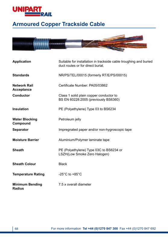
For more information Tel +44 (0)1270 847 300 Fax +44 (0)1270 847 69268
Armoured Copper Trackside Cable
Application
Standards
Conductor
Insulation
Sheath
Sheath Colour
Temperature Rating
Suitable for installation in trackside cable troughing and buried duct routes or for direct burial.
NR/PS/TEL/00015 (formerly RT/E/PS/00015)
Class 1 solid plain copper conductor to BS EN 60228:2005 (previously BS6360)
PE (Polyethylene) Type 03 to BS6234
PE (Polyethylene) Type 03C to BS6234 or LSZH(Low Smoke Zero Halogen)
Black
-25°C to +85°C
Minimum Bending Radius
7.5 x overall diameter
Water Blocking Compound
Separator
Moisture Barrier
Petroleum jelly
Impregnated paper and/or non-hygroscopic tape
Aluminium/Polymer laminate tape
Network Rail Acceptance
Certificate Number: PA05/03862
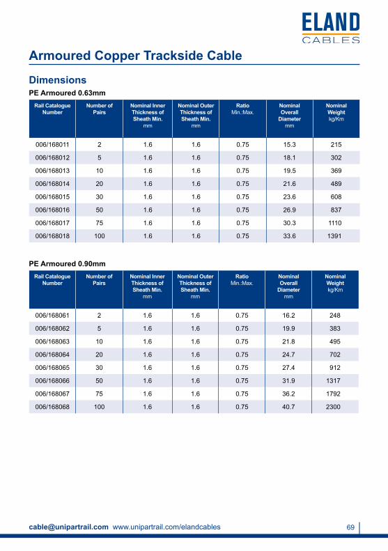
[email protected] www.unipartrail.com/elandcables 69
DimensionsPE Armoured 0.63mm
Rail Catalogue Number
Number of Pairs
Nominal Inner Thickness of Sheath Min.
mm
Nominal Outer Thickness of Sheath Min.
mm
RatioMin.:Max.
Nominal Overall
Diametermm
Nominal Weight kg/Km
006/168011 2 1.6 1.6 0.75 15.3 215
006/168012 5 1.6 1.6 0.75 18.1 302
006/168013 10 1.6 1.6 0.75 19.5 369
006/168014 20 1.6 1.6 0.75 21.6 489
006/168015 30 1.6 1.6 0.75 23.6 608
006/168016 50 1.6 1.6 0.75 26.9 837
006/168017 75 1.6 1.6 0.75 30.3 1110
006/168018 100 1.6 1.6 0.75 33.6 1391
Armoured Copper Trackside Cable
PE Armoured 0.90mmRail Catalogue
NumberNumber of
PairsNominal Inner Thickness of Sheath Min.
mm
Nominal Outer Thickness of Sheath Min.
mm
RatioMin.:Max.
Nominal Overall
Diametermm
Nominal Weight kg/Km
006/168061 2 1.6 1.6 0.75 16.2 248
006/168062 5 1.6 1.6 0.75 19.9 383
006/168063 10 1.6 1.6 0.75 21.8 495
006/168064 20 1.6 1.6 0.75 24.7 702
006/168065 30 1.6 1.6 0.75 27.4 912
006/168066 50 1.6 1.6 0.75 31.9 1317
006/168067 75 1.6 1.6 0.75 36.2 1792
006/168068 100 1.6 1.6 0.75 40.7 2300

For more information Tel +44 (0)1270 847 300 Fax +44 (0)1270 847 69270
2Pr 5Pr 10Pr 20Pr 30Pr 50Pr 75Pr 100Pr
Conductor Resistance 0.63mm (ohms/Km)
Max. Average at 20°C 58.0 58.0 58.0 58.0 58.0 58.0 58.0 58.0
Max. at 20°C 60.0 60.0 60.0 60.0 60.0 60.0 60.0 60.0
Conductor Resistance 0.90mm (ohms/Km)
Max. Average at 20°C 28.0 28.0 28.0 28.0 28.0 28.0 28.0 28.0
Max. at 20°C 30.0 30.0 30.0 30.0 30.0 30.0 30.0 30.0
Insulation Resistance Min. (Mohms/Km) 1500.0 1500.0 1500.0 1500.0 1500.0 1500.0 1500.0 1500.0
Mutual Capacitance (nF/Km) - - - - - - - -
Max. Average 70.0 70.0 70.0 70.0 67.0 67.0 67.0 67.0
Max. for 99% pairs 79.0 79.0 79.0 79.0 75.0 75.0 75.0 75.0
Capacitance Unbalance (Max. pF/500m) 800.0 275.0 275.0 275.0 275.0 275.0 275.0 275.0
Attenuation dB/Km Max. Average
0.63mm
1.0KHz - - - 1.40 1.40 1.40 1.40 1.40
2.4KHz - - - 2.15 2.15 2.15 2.15 2.15
1.024MHz - - - 18.70 18.70 18.70 18.70 18.70
Attenuation dB/Km Max. Average
0.90mm
1.0KHz - - - 0.95 0.95 0.95 0.95 0.95
2.4KHz - - - 1.46 1.46 1.46 1.46 1.46
1.024MHz - - - 14.60 14.60 14.60 14.60 14.60
NEXTA (dB) * (minimum)
1KHz - - - 70.00 70.00 70.00 70.00 70.00
1.024MHz (Within Units) - - - 40.00 40.00 40.00 40.00 40.00
1.024MHz (Between Units) - - - 47.00 47.00 47.00 47.00 47.00
Electrical Characteristics
* NEXTA at 1.0KHz shall have an average value better than 75dB.
Armoured Copper Trackside Cable

[email protected] www.unipartrail.com/elandcables 71
Copper Trackside Cable
Application
Standards
Conductor
Insulation
Sheath
Sheath Colour
Temperature Rating
Suitable for installation in trackside cable troughing and buried duct routes or for direct burial.
NR/PS/TEL/00015 (formerly RT/E/PS/00015)
Class 1 solid plain copper conductor to BS EN 60228:2005 (previously BS6360)
PE (Polyethylene) Type 03 to BS6234
PE (Polyethylene) Type 03C to BS6234 or LSZH (Low Smoke Zero Halogen)
Black
-25°C to +85°C
Minimum Bending Radius
7.5 x overall diameter
Water Blocking Compound
Separator
Moisture Barrier
Petroleum jelly
Impregnated paper and/or non-hygroscopic tape
Aluminium/Polymer laminate tape
Network Rail Acceptance
Certificate Number: PA05/03862
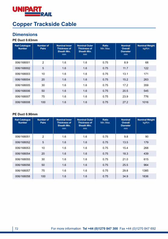
For more information Tel +44 (0)1270 847 300 Fax +44 (0)1270 847 69272
DimensionsPE Duct 0.63mm
Rail Catalogue Number
Number of Pairs
Nominal Inner Thickness of Sheath Min.
mm
Nominal Outer Thickness of Sheath Min.
mm
RatioMin.:Max.
Nominal Overall
Diametermm
Nominal Weight kg/Km
006/168001 2 1.6 1.6 0.75 8.9 68
006/168002 5 1.6 1.6 0.75 11.7 122
006/168003 10 1.6 1.6 0.75 13.1 171
006/168004 20 1.6 1.6 0.75 15.2 263
006/168005 30 1.6 1.6 0.75 17.2 359
006/168006 50 1.6 1.6 0.75 20.5 545
006/168007 75 1.6 1.6 0.75 23.9 776
006/168008 100 1.6 1.6 0.75 27.2 1016
Copper Trackside Cable
PE Duct 0.90mmRail Catalogue
NumberNumber of
PairsNominal Inner Thickness of Sheath Min.
mm
Nominal Outer Thickness of Sheath Min.
mm
RatioMin.:Max.
Nominal Overall
Diametermm
Nominal Weight kg/Km
006/168051 2 1.6 1.6 0.75 9.8 90
006/168052 5 1.6 1.6 0.75 13.5 179
006/168053 10 1.6 1.6 0.75 15.4 268
006/168054 20 1.6 1.6 0.75 18.3 439
006/168055 30 1.6 1.6 0.75 21.0 615
006/168056 50 1.6 1.6 0.75 25.5 964
006/168057 75 1.6 1.6 0.75 29.8 1385
006/168058 100 1.6 1.6 0.75 34.9 1836

[email protected] www.unipartrail.com/elandcables 73
2Pr 5Pr 10Pr 20Pr 30Pr 50Pr 75Pr 100Pr
Conductor Resistance 0.63mm(ohms/Km)
Max. Average at 20°C 58.0 58.0 58.0 58.0 58.0 58.0 58.0 58.0
Max. at 20°C 60.0 60.0 60.0 60.0 60.0 60.0 60.0 60.0
Conductor Resistance 0.90mm (ohms/Km)
Max. Average at 20°C 28.0 28.0 28.0 28.0 28.0 28.0 28.0 28.0
Max. at 20°C 30.0 30.0 30.0 30.0 30.0 30.0 30.0 30.0
Insulation Resistance Min. (Mohms/Km) 1500.0 1500.0 1500.0 1500.0 1500.0 1500.0 1500.0 1500.0
Mutual Capacitance (nF/Km) - - - - - - - -
Max. Average 70.0 70.0 70.0 70.0 67.0 67.0 67.0 67.0
Max. for 99% pairs 79.0 79.0 79.0 79.0 75.0 75.0 75.0 75.0
Capacitance Unbalance (Max. pF/500m) 800.0 275.0 275.0 275.0 275.0 275.0 275.0 275.0
Attenuation dB/Km Max. Average
0.63mm
1.0KHz - - - 1.40 1.40 1.40 1.40 1.40
2.4KHz - - - 2.15 2.15 2.15 2.15 2.15
1.024MHz - - - 18.70 18.70 18.70 18.70 18.70
Attenuation dB/Km Max. Average
0.90mm
1.0KHz - - - 0.95 0.95 0.95 0.95 0.95
2.4KHz - - - 1.46 1.46 1.46 1.46 1.46
1.024MHz - - - 14.60 14.60 14.60 14.60 14.60
NEXTA (dB) * (minimum)
1KHz - - - 70.00 70.00 70.00 70.00 70.00
1.024MHz (Within Units) - - - 40.00 40.00 40.00 40.00 40.00
1.024MHz (Between Units) - - - 47.00 47.00 47.00 47.00 47.00
Electrical Characteristics
* NEXTA at 1.0KHz shall have an average value better than 75dB.
Copper Trackside Cable

For more information Tel +44 (0)1270 847 300 Fax +44 (0)1270 847 69274
Fibre Trackside Cable
Application
Standards
Fibre
Fibre Carrier
Strength Member
Binding Type
Bedding
Sheath
Fibre communications cable for high traffic and data rate requirements.
NR/PS/TEL/00014(formerly RT/E/PS/00014)
Single mode fibre
PE (Polyethylene)
Single continuous non-metallic
Polymeric loose tubes filled with water blocking material
PE (Polyethylene) Type 03C to BS6234 or LSZH (Low Smoke Zero Halogen)
PE (Polyethylene) Type 03C to BS6234 orLSZH (Low Smoke Zero Halogen)
Sheath Colour
Temperature Rating
Minimum Bending Radius
Black
20°C to +60°C
12 x overall diameter

[email protected] www.unipartrail.com/elandcables 75
DimensionsRail
Catalogue Number
No. of Fibres
Nominal Thickness of Cladding
µm
Nominal Polymer
Tube Diameter
mm
Optical Attenuation
1290 - 1330nm
dB/Km
Optical Attenuation
1525 - 1575nm
dB/Km
Nominal Inner
Sheath Thickness
mm
Nominal Thickness of Sheath
mm
- 8 125 2.5 ≤ 0.37 ≤ 0.27 1.6 2.0
006/132511 12 125 2.5 ≤ 0.37 ≤ 0.27 1.6 2.0
006/169053 24 125 2.5 ≤ 0.37 ≤ 0.27 1.6 2.0
006/169013 48 125 2.5 ≤ 0.37 ≤ 0.27 1.6 2.0
- 96 125 2.5 ≤ 0.37 ≤ 0.27 1.6 2.0
Fibre Trackside Cable

For more information Tel +44 (0)1270 847 300 Fax +44 (0)1270 847 69276
FTN Screening Conductor Cable
Application
Standards
Conductor
Insulation
Insulation Colour
To be used for the purpose of screening telecommunication cables from electrical interference.
NR/PS/TEL/31102(BR1817)/BS6485
Single core stranded aluminium to BS215PT1
PVC (Polyvinyl Chloride) to BS6485
Black, Red, Yellow
Temperature Rating
Minimum Bending Radius
0°C to +70°C
9 x overall diameter
DimensionsRail
Catalogue Number
Sheath Colour
Drawing Number
No. of Cores x Nominal Cross
Sectional Area
# x mm²
Nominal Diameter of
Strands mm
Thickness of Sheath
Minmm
Nominal Overall
Diametermm
Nominal Weightkg/Km
Maximum DC
Resistance at 20°C
ohms/Km
091/010318 Black PVC 148/046/998 1 x 150 3.25 1.6 19.45 629 0.1825
091/010319 Black PVC 148/047/998 1 x 250 4.22 1.6 24.30 995 0.1083
091/030336 Red PVC 148/443/001 1 x 150 3.25 1.6 19.45 629 0.1825
091/030337 Yellow PVC 148/444/001 1 x 150 3.25 1.6 19.45 629 0.1825

[email protected] www.unipartrail.com/elandcables 77
SCADA / Pilot Cable
Application
Standards
Insulation
Filling Compound
Separator
Paired core compound-filled supervisory cables for modem based supervisory systems operating in the VF range 300 to 3000 Hz.
NR/PS/ELP/27220(formerly RT/E/PS/0034)
PE (Polyethylene) Type 03 to BS6234
Petroleum jelly
PETP (Polyethylene Terephthalate) tape
Network Rail AcceptanceConductor
Certificate Number: PA05/04015
Class 1 solid plain copper conductor 0.9mm nominal diameter to BS6360, complies to BS3573
Moisture Barrier Al/PE (Aluminium/Polyethylene) laminate
Bedding PE (Polyethylene) Type 03C to BS6234
Screen Aluminium wire
Separator Water blocking tape
Sheath PE (Polyethylene) Type 03C to BS6234
Sheath Colour Black
-25°C to +85°C
Minimum Bending Radius
10 x overall diameter
Temperature Rating

For more information Tel +44 (0)1270 847 300 Fax +44 (0)1270 847 69278
SCADA / Pilot Cable
DimensionsRail
Catalogue Number
No. of Pairs at 0.9mm
Nominal Thickness
of Insulation
mm
Average Mutual
Capacitance nF/Km
Maximum Capacitance Unbalance Between
PairsnF/500m
Nominal Thickness of Sheath
mm
Nominal Overall
Diametermm
Nominal Weightkg/Km
006/120030 10 0.3 71 275 1.8 25.8 755
006/122516 20 0.3 71 275 1.8 27.8 946
006/120031 30 0.3 71 275 2.0 31.8 1225
006/120032 20 0.3 71 275 1.8 27.8 946

[email protected] www.unipartrail.com/elandcables 79
Twin Datalink Cable
Application
Standards
Insulation
Interconnecting cable for Solid State Interlocking (SSI) systems.
BR1932
PE (Polyethylene)
Conductor Class 1 solid plain copper conductor (1/1.27)
Moisture Barrier Aluminium / Polyethylene laminated tape
Bedding PE (Polyethylene)
Temperature Rating
Minimum Bending Radius
-25°C to +85°C
6 x overall diameter
Sheath PE (Polyethylene)
Sheath Colour Black

For more information Tel +44 (0)1270 847 300 Fax +44 (0)1270 847 69280
DimensionsRail
Catalogue Number
Number of Pairs
Nominal Diameter
of Strandsmm
Nominal Thickness
of Insulation
mm
Nominal Thickness of Sheath
mm
Overall Diameter
Min.mm
Overall Diameter
Max.mm
Nominal Weightkg/Km
006/166065 1 1.27 0.66 2.5 12.47 12.8 135.53
Twin Datalink Cable
ConductorsClass 1 solid conductors for single core and multi-core cables
1 2 3
Nominal Cross Sectional Areamm²
Maximum Resistance of Conductor at 20˚C
Circular, Annealed Copper Conductors
Plain Wiresohms/Km
Metal-Coated Wiresohms/Km
2.50 7.4100 7.56
Table in accordance with BS EN 60228:2005 (previously BS6360).

[email protected] www.unipartrail.com/elandcables 81
Section 12 Fire Integrity Cable – London Underground
Application
Standards
Insulation
For installation typically in public help points (PHP), public address (PA), station announcement platforms (SAP) and CCTV camera power systems. This LSZH cable has been designed to provide superior flame retardance and circuit integrity, together with optimised ease of installation characteristics and complies with LU Section 12 station regulations.
BS7629-1, BS 5839-1:2002, BS 5839-1:2002, BS 8434-1:2003, BS EN 50200 PH30, BS 6387 C W Z, IEC 60332-3, IEC 60332-1, BS EN 50265, BS EN 50266, IEC 60754, BS EN 50267, IEC 61034, BS EN 50268
Silicone rubber
Conductor Class 1 solid or Class 2 stranded annealed plain copper conductors to BS EN 60228:2005 (previously BS6360)
Screen Aluminium / Polyester laminated tape
Separator Unspecified material
Drain Wire Tinned copper
Sheath High performance, thermoplastic LSZH (Low Smoke Zero Halogen)
Sheath Colour White
Voltage 300/500V
Temperature Rating -40°C to +90°CThis cable should not be flexed when either the ambient or cable temperature is below 0°C.
Minimum Bending Radius
Core Identification
6 x overall diameter
2 Cores: Brown, Blue3 Cores: Brown, Black, Grey4 Cores: Blue, Brown, Black, Grey7 Cores: Blue, Brown, Black, Grey

For more information Tel +44 (0)1270 847 300 Fax +44 (0)1270 847 69282
DimensionsNo. of Cores x Nominal Cross
Sectional Area# x mm²
Nominal Overall Diametermm
Nominal Weightkg/Km
2 x 1.00 7.0 83
2 x 1.50 7.9 110
2 x 2.50 9.3 160
3 x 1.00 7.3 95
3 x 1.50 8.3 128
3 x 2.50 9.9 190
4 x 1.00 8.2 115
4 x 1.50 9.5 160
4 x 2.50 11.3 235
7 x 1.00 10.5 175
7 x 1.50 12.2 250
Section 12 Fire Integrity Cable – London Underground
ConductorsClass 1 solid conductors for single core and multi-core cables
1 2
Norminal Cross Sectional Areamm²
Maximum Resistance of the Conductor at 20˚C
Circular, Annealed Copper Conductors
Plain Wiresohms/Km
1.00 18.1000
1.50 12.1000
2.50 7.4100
4.00 4.6100
Table in accordance with BS EN 60228:2005 (previously BS6360).

[email protected] www.unipartrail.com/elandcables 83
Section 12 Fire Integrity Cable – London UndergroundClass 2 stranded conductors for single core and multi-core cables
1 2 4 8
Nominal Cross
Sectional Areamm²
Minimum Number of Wires in the Conductor
Maximum Resistance of Conductor at 20ºC
Circular Circular Compacted
Annealed Copper Conductor
Cu CuPlain Wires
ohms/Km
1.00 7 - 18.1000
1.50 7 6 12.1000
2.50 7 6 7.4100
4.00 7 6 4.6100
Table in accordance with BS EN 60228:2005 (previously BS6360).
Electrical Characteristics
Nominal Cross Sectional Areamm²
Current Rating DC or Single Phase AC
EnclosedAmps
Current Rating DC or Single Phase AC
Amps
Volt Drop DC or Single Phase ACmV/A/m
1.00 13.0 15.0 44
1.50 16.5 19.5 29
2.50 23.0 27.0 18
4.00 30.0 36.0 11
Current Carrying Capacity (amperes)
Ambient Temperature 25°C 30°C 35°C 40°C 45°C 50°C
Rating Factor 1.03 1.00 0.94 0.60 0.57 0.54
Temperature Ratings Factor
Number of Circuits 2 3 4 5 6 7
Rating Factor 0.80 0.70 0.65 0.60 0.57 0.54
Rating Factors for Groupings

For more information Tel +44 (0)1270 847 300 Fax +44 (0)1270 847 69284
FireForce Fire Performance Cable PH30
Application
Standards
Insulation
For fixed installation typically in fire alarm and emergency lighting circuits where circuit integrity must be maintained. For use where fire, smoke emission and toxic fumes create a potential threat to life and equipment.
BS 7629-1, BS 6387 C W ZBS 5839-1 clause 26.2, BS EN 50200 PH30BS 8434-1
Special compound silicone and rubber mix
Conductor Class 1 solid plain copper conductors
Screen CAM (Collective Aluminium Mylar)
Separator Unspecified material
Drain Wire Tinned copper
Sheath LSZH (Low Smoke Zero Halogen)
Sheath Colour Red or White
Voltage 300/500V
Minimum Bending Radius
6 x overall diameter
Temperature Rating -30°C to +70°C
Core Identification 2 Cores: Brown, Blue4 Cores: Blue, Brown, Black, Grey

[email protected] www.unipartrail.com/elandcables 85
DimensionsNo. of Cores x Nominal Cross Sectional Area
# x mm²
Nominal Thickness of Insulation
mm
Nominal Thickness of Sheath
mm
Nominal Overall Diameter
mm
Nominal Weightkg/Km
2 x 1.50 0.7 1.4 8.07 101.39
2 x 2.50 0.8 1.4 9.09 141.86
4 x 1.50 0.7 1.4 9.08 150.51
4 x 2.50 0.8 1.5 11.05 222.00
ConductorsClass 1 Solid Conductors for single core and multi-core cables
1 2
Nominal Cross Sectional Areamm²
Maximum Resistance of the Conductor at 20˚C
Circular, Annealed Copper Conductors
Plain Wireohms/Km
1.50 12.1000
2.50 7.4100
Table in accordance with BS EN 60228:2005 (previously BS6360).
FireForce Fire Performance Cable PH30
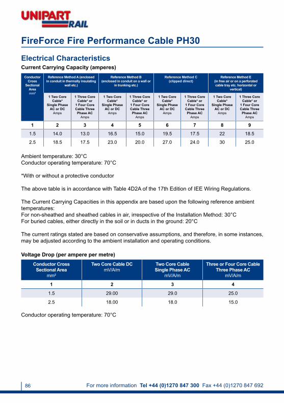
For more information Tel +44 (0)1270 847 300 Fax +44 (0)1270 847 69286
Conductor Cross
Sectional Areamm²
Reference Method A (enclosed in conduit in thermally insulating
wall etc.)
Reference Method B(enclosed in conduit on a wall or
in trunking etc.)
Reference Method C(clipped direct)
Reference Method E(in free air or on a perforated cable tray etc. horizontal or
vertical)
1 Two Core Cable*
Single Phase AC or DC
Amps
1 Three Core Cable* or
1 Four Core Cable Three Phase AC
Amps
1 Two Core Cable*
Single Phase AC or DC
Amps
1 Three Core Cable* or
1 Four Core Cable Three Phase AC
Amps
1 Two Core Cable*
Single Phase AC or DC
Amps
1 Three Core Cable* or
1 Four Core Cable Three Phase AC
Amps
1 Two Core Cable*
Single Phase AC or DC
Amps
1 Three Core Cable* or
1 Four Core Cable Three Phase AC
Amps
1 2 3 4 5 6 7 8 9
1.5 14.0 13.0 16.5 15.0 19.5 17.5 22 18.5
2.5 18.5 17.5 23.0 20.0 27.0 24.0 30 25.0
Electrical CharacteristicsCurrent Carrying Capacity (amperes)
Ambient temperature: 30°CConductor operating temperature: 70°C
*With or without a protective conductor
The above table is in accordance with Table 4D2A of the 17th Edition of IEE Wiring Regulations.
The Current Carrying Capacities in this appendix are based upon the following reference ambient temperatures:For non-sheathed and sheathed cables in air, irrespective of the Installation Method: 30°CFor buried cables, either directly in the soil or in ducts in the ground: 20°C
The current ratings stated are based on conservative assumptions, and therefore, in some instances, may be adjusted according to the ambient installation and operating conditions.
Conductor Cross Sectional Area
mm²
Two Core Cable DCmV/A/m
Two Core Cable Single Phase AC
mV/A/m
Three or Four Core CableThree Phase AC
mV/A/m
1 2 3 4
1.5 29.00 29.0 25.0
2.5 18.00 18.0 15.0
Voltage Drop (per ampere per metre)
Conductor operating temperature: 70°C
FireForce Fire Performance Cable PH30

[email protected] www.unipartrail.com/elandcables 87
Points Heating Cable
Application
Standards
Insulation
Designed for power distribution in points heating systems. These heavy duty cables offer protection from abrasion and mechanical impact whilst maintaining flexibility to ease installation.
NR/SP/ELP/40045(formerly RT/E/PS/40045) BS7919
EPR (Ethylene Propylene Rubber) insulation Type GP4 to BS7655
Conductor Class 5 flexible tinned copper conductors to BS EN 60228:2005 (previously BS6360)
Separator Unspecified material
Core Identification 4 cores (in order of rotation):Yellow/Yellow, Blue/Blue
8 cores (in order of rotation):Yellow/Yellow, Blue/Blue, Brown/Brown, Black/Black
Sheath PCP (Polychloroprene) Type EM2 to BS7655
Sheath Colour Black

For more information Tel +44 (0)1270 847 300 Fax +44 (0)1270 847 69288
DimensionsRail
Catalogue Number
Number of Cores
Nominal Conductor
Areamm²
No. and Diameter of
Strands # / mm
Overall Diameter
Minmm
Overall Diameter
Maxmm
Nominal Weightkg/Km
Thickness of
Insulationmm
006/150002 4 1.5 30/0.25 13.80 14.30 220 0.8
- 4 2.5 50/0.25 16.00 16.50 390 0.9
- 4 4.0 56/0.30 18.00 18.50 420 1.0
006/153102 8 1.5 30/0.25 17.90 18.50 460 0.8
- 8 2.5 50/0.25 21.00 21.80 690 0.9
006/153103 8 4.0 56/0.30 22.60 23.60 830 1.0
- 8 6.0 84/0.30 24.50 25.50 1010 1.0
ConductorsClass 5 flexible copper conductors for single core and multi-core cables
1 2 4
Nominal Cross Sectional Area
mm²
Maximum Diameter of Wires in Conductor
mm
Maximum Resistance of the Conductor at 20˚C
Metal-Coated Wires at 20°Cohms/Km
1.50 0.26 13.7000
2.50 0.26 8.2100
4.00 0.31 5.0900
6.00 0.31 3.3900
Table in accordance with BS EN 60228:2005 (previously BS6360).
Points Heating Cable

[email protected] www.unipartrail.com/elandcables 89
Bare Conductor
Application
Standards
Conductor
To be used for the purpose of screening telecommunication cables from electrical interference.
NR/PS/TEL/31102 (BR1817), BS6485
Single core stranded aluminium to BS215PT1
Temperature Rating
Minimum Bending Radius
0°C to +70°C
9 x overall diameter
DimensionsRail
Catalogue Number
Drawing Number
No. of Cores x Nominal
Cross Sectional
Area# x mm²
Nominal Diameter of
Strands mm
Nominal Overall
Diametermm
Nominal Weightkg/Km
Maximum DC Resistance at
20°Cohms/Km
091/010267 148/044/998 1 x 150 3.25 16.25 443 0.1825
091/010268 148/045/998 1 x 250 4.22 21.10 754 0.1083

For more information Tel +44 (0)1270 847 300 Fax +44 (0)1270 847 69290
Screening Conductor PVC Cable
Application
Standards
Conductor
To be used for the purpose of screening telecommunication cables from electrical interference.
NR/PS/TEL/31102(BR1817)/BS6485
Single core stranded aluminium to BS215PT1
Temperature Rating
Minimum Bending Radius
0°C to +70°C
9 x overall diameter
Dimensions
Insulation
Insulation Colour
PVC (Polyvinyl Chloride) to BS6485
Black, Red, Yellow
Rail Catalogue Number
Sheath Colour
Drawing Number
No. of Cores x Nominal Cross
Sectional Area
# x mm²
Nominal Diameter
of Strands
mm
Thickness of Sheath
Minmm
Nominal Overall
Diametermm
Nominal Weightkg/Km
Maximum DC
Resistance at 20°C
ohms/Km
091/010318 Black PVC 148/046/998 1 x 150 3.25 1.6 19.45 629 0.1825
091/010319 Black PVC 148/047/998 2 x 250 4.22 1.6 24.30 995 0.1083
091/030336 Red PVC 148/443/001 1 x 150 3.25 1.6 19.45 629 0.1825
091/030337 Yellow PVC 148/444/001 1 x 150 3.25 1.6 19.45 629 0.1825

[email protected] www.unipartrail.com/elandcables 91
Screening Conductor LSZH Cable
Application
Standards
Conductor
To be used for the purpose of screening telecommunication cables from electrical interference.
NR/PS/TEL/31102(BR1817)/BS6485
Single core stranded aluminium to BS215PT1
Temperature Rating
Minimum Bending Radius
0°C to +70°C
9 x overall diameter
Dimensions
Insulation
Insulation Colour
LSZH (Low Smoke Zero Halogen)
Black
Rail Catalogue Number
Drawing Number
No. of Cores x Nominal Cross
Sectional Area
# x mm²
Nominal Diameter
of Strands mm
Thickness of Sheath
Min.mm
Nominal Overall
Diametermm
Nominal Weightkg/Km
Maximum DC
Resistance at 20°C
ohms/Km
091/012189 148/863/998 1 x 150 3.25 1.6 19.45 629 0.1825
091/012190 148/864/998 1 x 250 4.22 1.6 24.30 995 0.1083

For more information Tel +44 (0)1270 847 300 Fax +44 (0)1270 847 69292
Coaxial Cable URM70
Application
Conductor
Dialectric
Coaxial cable used for CCTV, video signal connections, and monitored barriers at level crossings.
PCW (Plain Copper Wire)
PE (Polyethylene)
Sheath Colour
Voltage Rating
Black or White
30V
Dimensions
Braiding
Sheath
Bare copper braid
PVC (Polyvinyl Chloride)
Rail Catalogue Number
Cable Type No. and Nominal
Diameter of Strands# x mm
Nominal Thickness of
Dielectric mm
Nominal Overall Diameter
mm
Nominal Weightkg/Km
006/165543 URM70 7/0.19 3.20 5.80 46.0
Temperature Rating 60ºC
Electrical CharacteristicsCoaxial Cable Nominal Capacitance
pF/mtrImpedance
ohmsVelocity Ratio
%
URM70 67 75 66.6

[email protected] www.unipartrail.com/elandcables 93
Accessories
A full range of accessories is also available from Unipart Rail. These include:
TrunkingCable ClampsCable Jointing Kits (LV and MV)CrimpsCable TiesCable MarkersTrack Connection CablesJunction Blocks (Points Heating)GlandsTerminalsLugsHeatshrinkColdshrinkSleevingDuctingCleatsEnd Caps
Visit www.unipartrail.com/catalogue to view these and other products in the range.

For more information Tel +44 (0)1270 847 300 Fax +44 (0)1270 847 69294

[email protected] www.unipartrail.com/elandcables 95

For more information Tel +44 (0)1270 847 300 Fax +44 (0)1270 847 69296
Issue 1: September 2009
The information contained within this handbook is of indicative reference only. For specific information on product application, please contact us as above.
Unipart Rail and Eland Cables have used best endeavours to ensure information contained was as up-to-date as possible at time of press.
Unipart Rail and Eland Cables accept no liability for changes to specifications and updates not published or contained within this handbook.
Cables for railway applications from Eland Cables are distributed exclusively
through Unipart Rail.
Cable TeamUnipart RailGresty Road
CreweCheshireCW2 6EH
Tel +44 (0)1270 847 300Fax +44 (0)1270 847 692
Email [email protected]
www.unipartrail.com/elandcables
Out-of-hours emergency contact: +44 (0)1270 847 600