Embed Size (px)
Citation preview

application notePhilips Magnetic Products
Philips Components
Cable Shielding
1Philips Magnetic Products
Cable Shielding
Contents
Introduction 3
EMI suppression and cable shieldingwith ferrites 4
Ferrite selection 6
Material properties 7
Ferrite core and its impedance behaviour 11
Ferrite location 12
Impedance concept 13
Attenuation concept 16
Product range 17
2Philips Magnetic Products
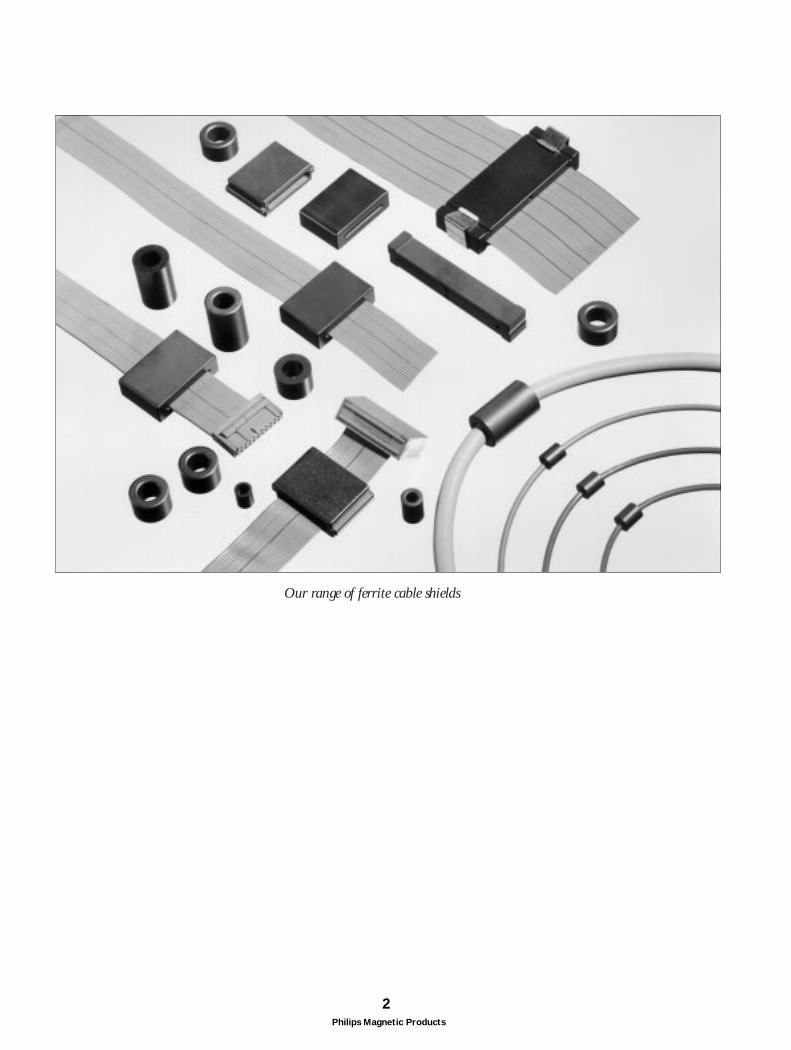
Our range of ferrite cable shields
3Philips Magnetic Products
Conductive coupling is the most common way aninterference signal is transmitted to a system. When studying an interference problem, very oftenattention is focused on critical components, while systemcables are overlooked.A cable can pick up some noise and bring it to other areastraversed by the cable.
With today’s regulations (VDE in Germany, FCC in USA,VCCI in Japan), all electric and electronic products, nomatter how trivial they seem to be, have to comply withcertain EMC limits, both for emission and reception.
There is a need to suppress common mode EMI not onlyon internal, but also on external cables of electronicequipment.
PHILIPS COMPONENTS developed a new range ofcable shielding products.There are tubular cable shields for coaxial cable andrectangular cores for flat ribbon cables. Also split types forretrofit solutions are available.These EMI products provide a high impedance level over awide frequency range.
Ferrite cable shields are cost-effective, as they suppress anyelectromagnetic noise and reduce the need for other, morecomplicated, shielding measures.
source of interference
system disturbed by interference
coupling
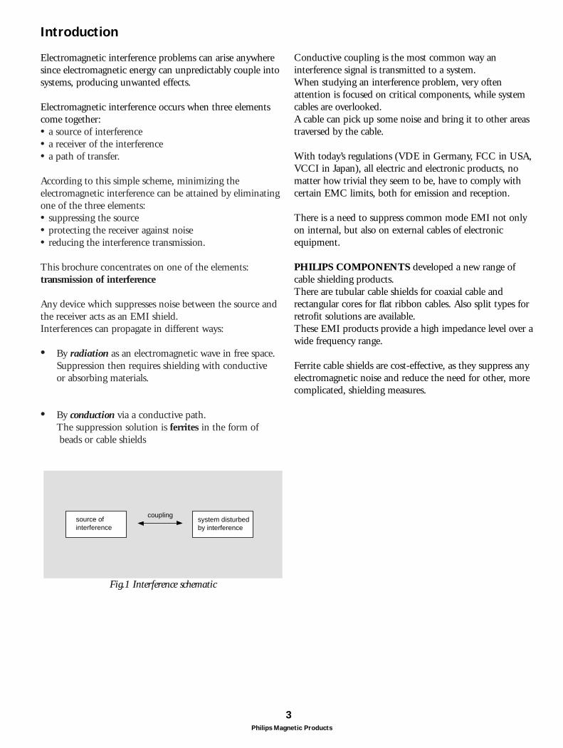
Fig.1 Interference schematic
Introduction
Electromagnetic interference problems can arise anywheresince electromagnetic energy can unpredictably couple intosystems, producing unwanted effects.
Electromagnetic interference occurs when three elementscome together:• a source of interference• a receiver of the interference • a path of transfer.
According to this simple scheme, minimizing theelectromagnetic interference can be attained by eliminatingone of the three elements:• suppressing the source• protecting the receiver against noise• reducing the interference transmission.
This brochure concentrates on one of the elements:transmission of interference
Any device which suppresses noise between the source and the receiver acts as an EMI shield. Interferences can propagate in different ways:
• By radiation as an electromagnetic wave in free space.Suppression then requires shielding with conductive or absorbing materials.
• By conduction via a conductive path. The suppression solution is ferrites in the form of beads or cable shields
EMI suppression and cable shieldingwith ferrites
Ferrite shields provide an excellent method to suppressconducted interferences on cables. Cables can act asantennas and radiate RFI power at frequencies above30MHz. They are a cost-effective alternative to othersuppression solutions, like EMI filters or completeshielding.
Applications for cable shielding are found intelecommunication, instrumentation, electronic dataprocessing (EDP) in places like:
• Internal and external computer data cables (for monitors, printers, CPU, keyboards...)
• Internal and external power cables
• Internal floppy disk and hard disk ribbon cables
• Cables between PC board and data connectors, ...
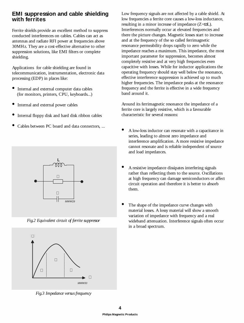
Low frequency signals are not affected by a cable shield. Atlow frequencies a ferrite core causes a low-loss inductance,resulting in a minor increase of impedance (Z=ωL).Interferences normally occur at elevated frequencies andthere the picture changes. Magnetic losses start to increaseand at the frequency of the so called ferrimagneticresonance permeability drops rapidly to zero while theimpedance reaches a maximum. This impedance, the mostimportant parameter for suppression, becomes almostcompletely resistive and at very high frequencies evencapacitive with losses. While for inductor applications theoperating frequency should stay well below the resonance,effective interference suppression is achieved up to muchhigher frequencies. The impedance peaks at the resonancefrequency and the ferrite is effective in a wide frequencyband around it.
Around its ferrimagnetic resonance the impedance of aferrite core is largely resistive, which is a favourablecharacteristic for several reasons:
• A low-loss inductor can resonate with a capacitance inseries, leading to almost zero impedance and interference amplification. A more resistive impedancecannot resonate and is reliable independent of source and load impedances.
• A resistive impedance dissipates interfering signals rather than reflecting them to the source. Oscillations at high frequency can damage semiconductors or affect circuit operation and therefore it is better to absorb them.
• The shape of the impedance curve changes with material losses. A lossy material will show a smooth variation of impedance with frequency and a real wideband attenuation. Interference signals often occur in a broad spectrum.
4Philips Magnetic Products
L
R
C
MWW29
Z
f
L
R
C
MWW30
Fig.2 Equivalent circuit of ferrite suppressor
Fig.3 Impedance versus frequency
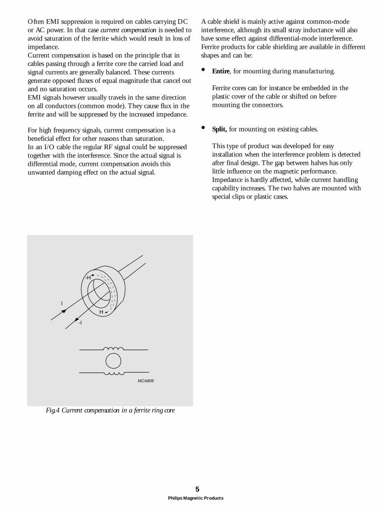
Often EMI suppression is required on cables carrying DCor AC power. In that case current compensation is needed toavoid saturation of the ferrite which would result in loss ofimpedance.Current compensation is based on the principle that incables passing through a ferrite core the carried load andsignal currents are generally balanced. These currentsgenerate opposed fluxes of equal magnitude that cancel outand no saturation occurs. EMI signals however usually travels in the same directionon all conductors (common mode). They cause flux in theferrite and will be suppressed by the increased impedance.
For high frequency signals, current compensation is abeneficial effect for other reasons than saturation. In an I/O cable the regular RF signal could be suppressedtogether with the interference. Since the actual signal isdifferential mode, current compensation avoids thisunwanted damping effect on the actual signal.
5Philips Magnetic Products
MCA808
I
-I
H
-H
Fig.4 Current compensation in a ferrite ring core
A cable shield is mainly active against common-modeinterference, although its small stray inductance will also have some effect against differential-mode interference.Ferrite products for cable shielding are available in differentshapes and can be:
• Entire, for mounting during manufacturing.
Ferrite cores can for instance be embedded in the plastic cover of the cable or shifted on before mounting the connectors.
• Split, for mounting on existing cables.
This type of product was developed for easy installation when the interference problem is detected after final design. The gap between halves has only little influence on the magnetic performance. Impedance is hardly affected, while current handling capability increases. The two halves are mounted with special clips or plastic cases.
6Philips Magnetic Products
Ferrite selection
When selecting a ferrite cable shield to solve aninterference problem it is necessary to consider someimportant application aspects:
• The frequency were maximum attenuation is neededwill determine material requirements. The most suitable ferrite would offer the highest impedance levels at the interference frequencies, which usually cover a broad spectrum.
• Core shape, which is usually defined by the cabletype.
• Installation requirements to decide on an entire orsplit core type.
• Attenuation/impedance level for maximum suppression.
• Ferrite characteristics as a function of operating conditions. Impedance can vary with temperature or DC current.
Material characteristics
NiZn ferrites used to be the only suitable material for EMIsuppression up to GHz frequencies. Their high resistivity(105 Ωm) ensures that eddy currents can never be inducedin these ferrites. As a result they maintain an excellentmagnetic performance up to very high frequencies.
The new MnZn material 3S4, however, does suppress EMIup to frequencies of 1GHz and higher, making it anattractive alternative to NiZn materials. Up to now the low resistivity of MnZn ferrites (1 to 10 Ωm) has limited their operation to a maximum ofabout 30MHz. With 3S4 precise control of materialcomposition has resulted in an increase of its resistivity to avalue of 103 Ωm, intermediate between the standardMnZn and NiZn grades, but high enough for effectiveRFI-suppression into the GHz region.
Additional advantage of 3S4 is that it does not containnickel which is a heavy metal and therefore a potentialhazard to the environment. Also, its high permeabilitygives it excellent low-frequency characteristics.
7Philips Magnetic Products
MBW195
1 10 102
10 4
f (MHz)
µ' ,s µ''s
10 3
10 2
1010 1
3S4
µ''s
µ' s
5000
50 50 2500
MBW191
150
1000
2000
3000
4000
3S4µi
T (oC)
50 100 1000
500
0
MBW199
500
100
200
300
400
500H (A/m)
B(mT)
3S425oC
100oC
150
0
100
1
MBW221
10 102 103
50
Z(Ω)
f (MHz)
3S4
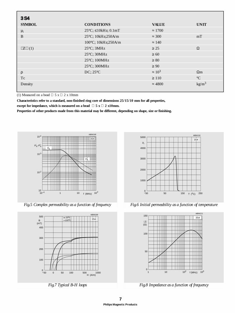
Characteristics refer to a standard, non-finished ring core of dimensions 25/15/10 mm for all properties,
except for impedance, which is measured on a bead ∅ 5 x ∅ 2 x10mm.
Properties of other products made from this material may be different, depending on shape, size or finishing.
Fig.5 Complex permeability as a function of frequency Fig.6 Initial permeability as a function of temperature
Fig.7 Typical B-H loops Fig.8 Impedance as a function of frequency
33SS4433SS44SYMBOL CONDITIONS VALUE UNIT
µi 25°C; ≤10kHz; 0.1mT ≈ 1700
B 25°C; 10kHz;250A/m ≈ 300 mT
100°C; 10kHz;250A/m ≈ 140
Z (1) 25°C; 3MHz ≥ 25 Ω25°C; 30MHz ≥ 60
25°C; 100MHz ≥ 80
25°C; 300MHz ≥ 90
ρ DC; 25°C ≈ 103 Ωm
Tc ≥ 110 °C
Density ≈ 4800 kg/m3
(1) Measured on a bead ∅ 5 x ∅ 2 x 10mm
8Philips Magnetic Products
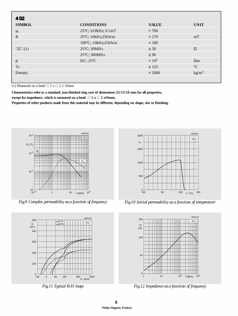
44SS2244SS22SYMBOL CONDITIONS VALUE UNIT
µi 25°C; ≤10kHz; 0.1mT ≈ 700
B 25°C; 10kHz;250A/m ≈ 270 mT
100°C; 10kHz;250A/m ≈ 180
Z (1) 25°C; 30MHz ≥ 50 Ω25°C; 300MHz ≥ 90
ρ DC; 25°C ≈ 105 Ωm
Tc ≥ 125 °C
Density ≈ 5000 kg/m3
(1) Measured on a bead ∅ 5 x ∅ 2 x 10mm
MBW306
1 10 102
10 4
f (MHz)
µ' ,s µ''s
10 3
10 2
1010 1
4S2
µ''s
µ' s
Fig.9 Complex permeability as a function of frequency
150
0
100
1
MBW220
10 102 103
50
Z(Ω)
f (MHz)
4S2
Fig.12 Impedance as a function of frequency
2000
50 50 2500
MBW307
150
500
1000
1500
µ i
T ( C)o
4S2
Fig.10 Initial permeability as a function of temperature
50 100 1000
500
0
MBW308
500
100
200
300
400
500H (A/m)
B(mT)
4S225 oC
100 oC
Fig.11 Typical B-H loops
Characteristics refer to a standard, non-finished ring core of dimensions 25/15/10 mm for all properties,
except for impedance, which is measured on a bead ∅ 5 x ∅ 2 x10mm.
Properties of other products made from this material may be different, depending on shape, size or finishing.
9Philips Magnetic Products
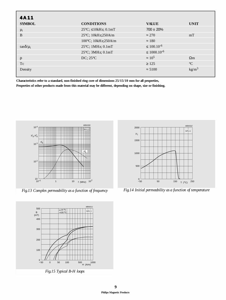
44AA111144AA1111SYMBOL CONDITIONS VALUE UNIT
µi 25°C; ≤10kHz; 0.1mT 700 ± 20%B 25°C; 10kHz;250A/m ≈ 270 mT
100°C; 10kHz;250A/m ≈ 180
tanδ/µi 25°C; 1MHz; 0.1mT ≤ 100.10-6
25°C; 3MHz; 0.1mT ≤ 1000.10-6
ρ DC; 25°C ≈ 105 Ωm
Tc ≥ 125 °C
Density ≈ 5100 kg/m3
MBW309
1 10 102
10 4
f (MHz)
µ' ,s µ''s
10 3
10 2
1010 1
4A11
µ''s
µ' s
Fig.13 Complex permeability as a function of frequency
50 100 1000
500
0
MBW311
500
100
200
300
400
500H (A/m)
B(mT)
4A1125 oC
100 oC
Fig.15 Typical B-H loops
2000
50 50 2500
MBW310
150
500
1000
1500
µ i
T ( C)o
4A11
Fig.14 Initial permeability as a function of temperature
Characteristics refer to a standard, non-finished ring core of dimensions 25/15/10 mm for all properties,
Properties of other products made from this material may be different, depending on shape, size or finishing.
10Philips Magnetic Products
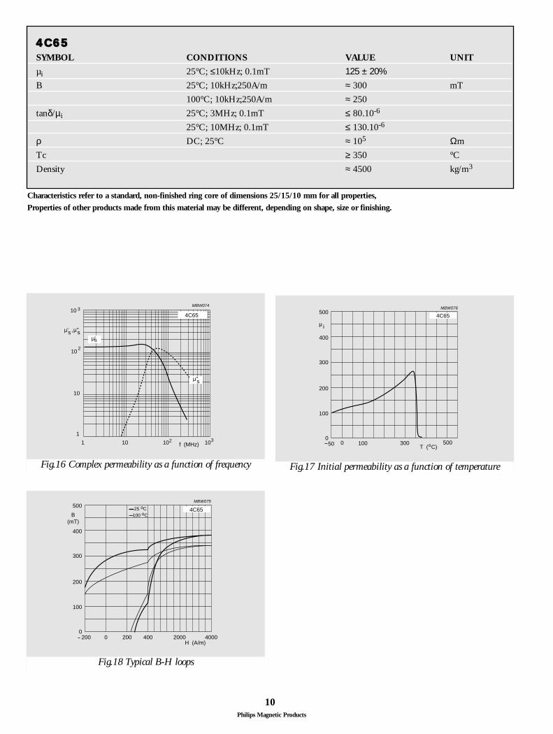
44CC665544CC6655SYMBOL CONDITIONS VALUE UNIT
µi 25°C; ≤10kHz; 0.1mT 125 ± 20%B 25°C; 10kHz;250A/m ≈ 300 mT
100°C; 10kHz;250A/m ≈ 250
tanδ/µi 25°C; 3MHz; 0.1mT ≤ 80.10-6
25°C; 10MHz; 0.1mT ≤ 130.10-6
ρ DC; 25°C ≈ 105 Ωm
Tc ≥ 350 °C
Density ≈ 4500 kg/m3
1
MBW074
10 102 1031
10 3
10
f (MHz)
µ' ,s µ''s
4C65
10 2
µ' s
µ''s
Fig.16 Complex permeability as a function of frequency
500
50 100 5000
MBW076
300
100
200
300
400
µ i
T ( C)o
4C65
0
Fig.17 Initial permeability as a function of temperature
200 400 4000
500
0
MBW075
2000
100
200
300
400
2000H (A/m)
B(mT)
4C6525 oC100 oC
Fig.18 Typical B-H loops
Characteristics refer to a standard, non-finished ring core of dimensions 25/15/10 mm for all properties,
Properties of other products made from this material may be different, depending on shape, size or finishing.
11Philips Magnetic Products
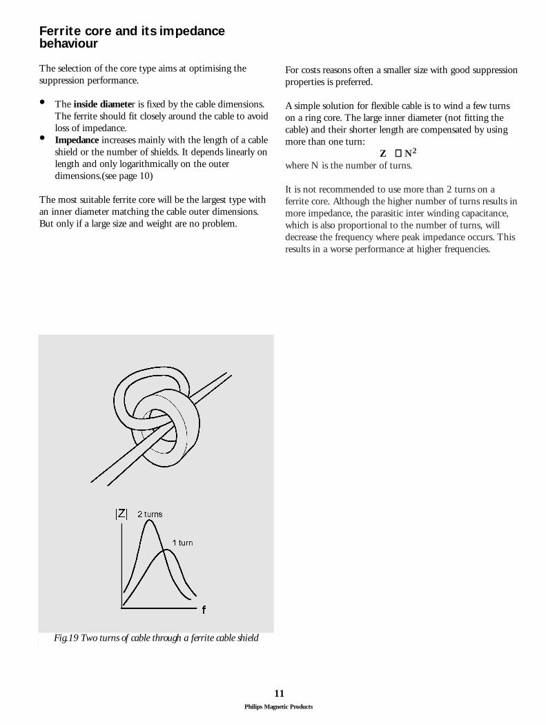
Ferrite core and its impedancebehaviour
The selection of the core type aims at optimising thesuppression performance.
• The inside diameter is fixed by the cable dimensions.The ferrite should fit closely around the cable to avoid loss of impedance.
• Impedance increases mainly with the length of a cable shield or the number of shields. It depends linearly on length and only logarithmically on the outer dimensions.(see page 10)
The most suitable ferrite core will be the largest type withan inner diameter matching the cable outer dimensions.But only if a large size and weight are no problem.
Fig.19 Two turns of cable through a ferrite cable shield
For costs reasons often a smaller size with good suppressionproperties is preferred.
A simple solution for flexible cable is to wind a few turnson a ring core. The large inner diameter (not fitting thecable) and their shorter length are compensated by usingmore than one turn:
Z ∝∝ N2
where N is the number of turns.
It is not recommended to use more than 2 turns on aferrite core. Although the higher number of turns results inmore impedance, the parasitic inter winding capacitance,which is also proportional to the number of turns, willdecrease the frequency where peak impedance occurs. Thisresults in a worse performance at higher frequencies.
12Philips Magnetic Products
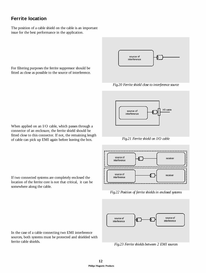
Ferrite location
The position of a cable shield on the cable is an importantissue for the best performance in the application.
In the case of a cable connecting two EMI interferencesources, both systems must be protected and shielded withferrite cable shields.
If two connected systems are completely enclosed thelocation of the ferrite core is not that critical, it can besomewhere along the cable.
When applied on an I/O cable, which passes through aconnector of an enclosure, the ferrite shield should befitted close to this connector. If not, the remaining lengthof cable can pick up EMI again before leaving the box.
For filtering purposes the ferrite suppressor should befitted as close as possible to the source of interference.
Fig.20 Ferrite shield close to interference source
Fig.21 Ferrite shield on I/O cable
Fig.22 Position of ferrite shields in enclosed systems
Fig.23 Ferrite shields between 2 EMI sources
13Philips Magnetic Products
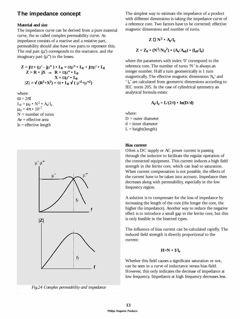
Fig.24 Complex permeability and impedance
The impedance concept
Material and sizeThe impedance curve can be derived from a pure materialcurve, the so called complex permeability curve. Asimpedance consists of a reactive and a resistive part,permeability should also have two parts to represent this.The real part (µ’) corresponds to the reactance, and theimaginary part (µ’’) to the losses.
Z = jω • (µ’ - jµ’’ ) • L0 = ωµ’’ • L0 + jωµ’ • L0Z = R + jX →→ R = ωµ’’ • L0
X = ωµ’ • L0|Z| = √√ (R2+X2) = ω • L0 √√ ( µ’2+µ’’2)
where:ω = 2πfL0 = µ0 • N2 • Ae/leµ0 = 4π • 10-7
N = number of turnsAe = effective areale = effective length
The simplest way to estimate the impedance of a productwith different dimensions is taking the impedance curve ofa reference core. Two factors have to be corrected: effectivemagnetic dimensions and number of turns.
Z ∝∝ N2 • Ae/le
Z = Z0 • (N2/N02) • (Ae/Ae0) • (le0/le)
where the parameters with index ‘0’ correspond to thereference core. The number of turns ‘N’ is always aninteger number. Half a turn geometrically is 1 turnmagnetically. The effective magnetic dimensions ‘Ae’ and‘ le’ are calculated from geometric dimensions according toIEC norm 205. In the case of cylindrical symmetry ananalytical formula exists:
Ae/le = L/(2π) • ln(D/d)
where:D = outer diameterd = inner diameterL = height(length)
Bias currentOften a DC supply or AC power current is passingthrough the inductor to facilitate the regular operation ofthe connected equipment. This current induces a high fieldstrength in the ferrite core, which can lead to saturation.When current compensation is not possible, the effects ofthe current have to be taken into account. Impedance thendecreases along with permeability, especially in the lowfrequency region.
A solution is to compensate for the loss of impedance byincreasing the length of the core (the longer the core, thehigher the impedance). Another way to reduce the negativeeffect is to introduce a small gap in the ferrite core, but thisis only feasible in the bisected types.
The influence of bias current can be calculated rapidly. Theinduced field strength is directly proportional to thecurrent:
H=N • I/le
Whether this field causes a significant saturation or not,can be seen in a curve of inductance versus bias field.However, this only indicates the decrease of impedance atlow frequency. Impedance at high frequency decreases less.
14Philips Magnetic Products
1
MWW26
10 102 1031
10 3
10
f (MHz)
10 2
1
2
1 = 0 A
2 = 1 A
3 = 3 A
3
4
4 = 5 A
5 = 10 A
5
Z(Ω)
1
MWW27
10 102 1031
10 3
10
f (MHz)
10 2
1
2
1 = 0 A
2 = 0.5 A
3 = 1 A
3
4
4 = 3 A
5 = 5 A
5 6
6 = 10 A
Z(Ω)
1
MWW25
10 102 1031
10 3
10
f (MHz)
10 2
1
2
1 = 0 A
2 = 3 A
3 = 5 A
3
4
4 = 10 A
Z(Ω)
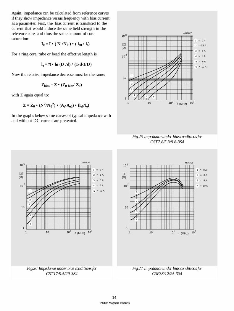
Fig.25 Impedance under bias conditions for CST7.8/5.3/9.8-3S4
Fig.26 Impedance under bias conditions for CST17/9.5/29-3S4
Fig.27 Impedance under bias conditions for CSF38/12/25-3S4
Again, impedance can be calculated from reference curvesif they show impedance versus frequency with bias currentas a parameter. First, the bias current is translated to thecurrent that would induce the same field strength in thereference core, and thus the same amount of coresaturation:
I0 = I • ( N /N0 ) • ( le0 / le)
For a ring core, tube or bead the effective length is:
le = π • ln (D /d) / (1/d-1/D)
Now the relative impedance decrease must be the same:
Zbias = Z • (Z0 bias/ Z0)
with Z again equal to:
Z = Z0 • (N2/N02) • (Ae/Ae0) • (le0/le)
In the graphs below some curves of typical impedance withand without DC current are presented.
15Philips Magnetic Products
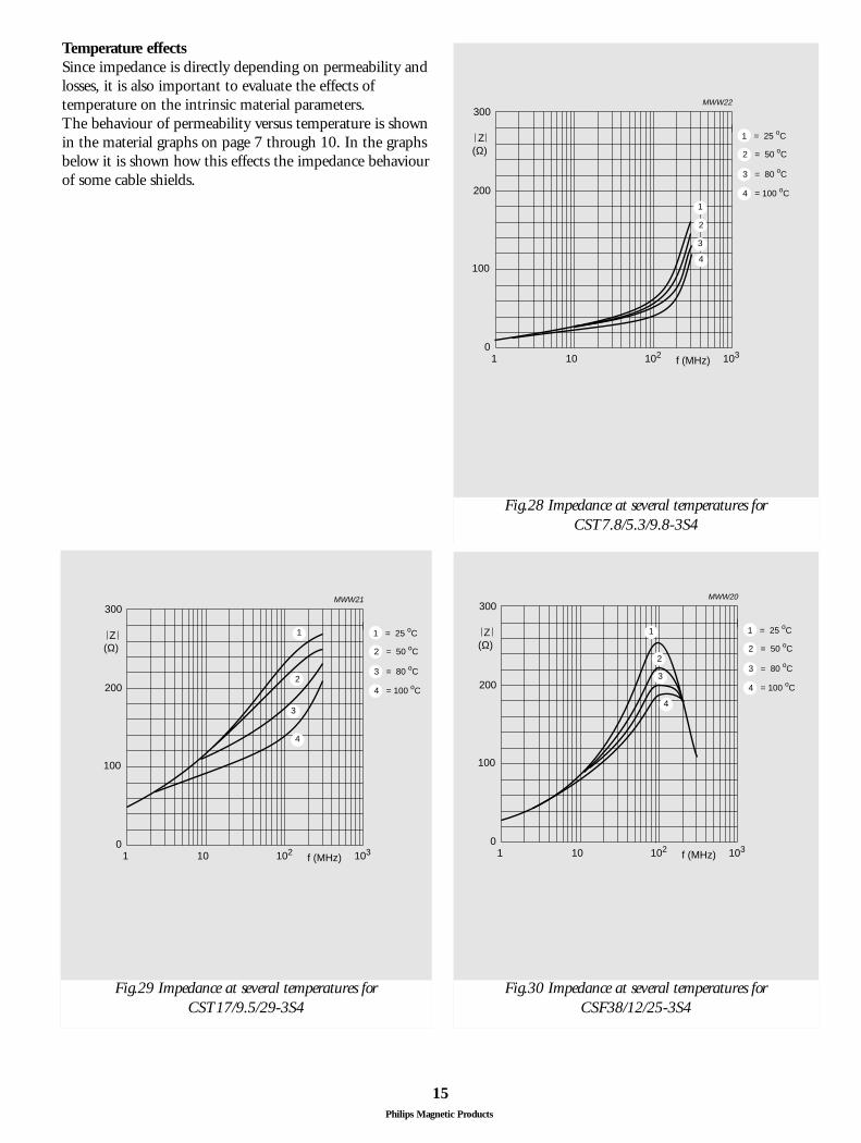
Temperature effectsSince impedance is directly depending on permeability andlosses, it is also important to evaluate the effects oftemperature on the intrinsic material parameters. The behaviour of permeability versus temperature is shownin the material graphs on page 7 through 10. In the graphsbelow it is shown how this effects the impedance behaviourof some cable shields.
300
0
200
1
MWW21
10 102 103
100
Z(Ω)
f (MHz)
1
2
1 = 25 oC
2 = 50 oC
3 = 80 oC
4 = 100 oC
3
4
300
0
200
1
MWW22
10 102 103
100
Z(Ω)
f (MHz)
1
2
1 = 25 oC
2 = 50 oC
3 = 80 oC
4 = 100 oC
3
4
300
0
200
1
MWW20
10 102 103
100
Z(Ω)
f (MHz)
1
2
1 = 25 oC
2 = 50 oC
3 = 80 oC
4 = 100 oC3
4
Fig.28 Impedance at several temperatures for CST7.8/5.3/9.8-3S4
Fig.30 Impedance at several temperatures for CSF38/12/25-3S4
Fig.29 Impedance at several temperatures for CST17/9.5/29-3S4
16Philips Magnetic Products
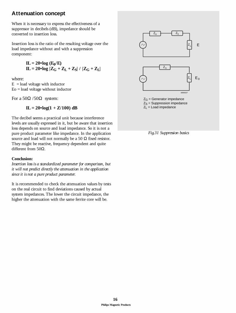
Attenuation concept
When it is necessary to express the effectiveness of asuppressor in decibels (dB), impedance should beconverted to insertion loss.
Insertion loss is the ratio of the resulting voltage over theload impedance without and with a suppressioncomponent:
IL = 20•log (E0/E)IL = 20•log |ZG + ZL + ZS| / |ZG + ZL|
where:E = load voltage with inductorEo = load voltage without inductor
For a 50Ω /50Ω system:
IL = 20•log(1 + Z/100) dB
The decibel seems a practical unit because interferencelevels are usually expressed in it, but be aware that insertionloss depends on source and load impedance. So it is not apure product parameter like impedance. In the applicationsource and load will not normally be a 50 Ω fixed resistor.They might be reactive, frequency dependent and quitedifferent from 50Ω.
Conclusion:Insertion loss is a standardized parameter for comparison, butit will not predict directly the attenuation in the applicationsince it is not a pure product parameter.
It is recommended to check the attenuation values by testson the real circuit to find deviations caused by actualsystem impedances. The lower the circuit impedance, thehigher the attenuation with the same ferrite core will be.
ZG
ZG
ZS
LZ
LZ
E
E 0
ZG = Generator impedanceZS = Suppression impedanceZL = Load impedance
MWW37
Fig.31 Suppression basics
Philips Magnetic Products
17
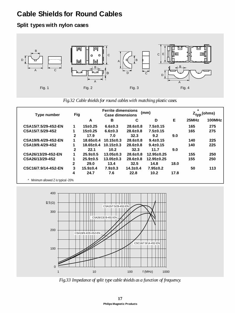
Cable Shields for Round Cables
CA
D
B
A
B
C
A
B
BA
C
EC
D
Fig. 1 Fig. 2 Fig. 3 Fig. 4
D D
CSA15/7.5/29-4S2-EN 1 15±0.25 6.6±0.3 28.6±0.8 7.5±0.15 165 275 CSA15/7.5/29-4S2 1 15±0.25 6.6±0.3 28.6±0.8 7.5±0.15 165 275 2 17.9 7.0 32.3 9.2 9.0 CSA19/9.4/29-4S2-EN 1 18.65±0.4 10.15±0.3 28.6±0.8 9.4±0.15 140 225 CSA19/9.4/29-4S2 1 18.65±0.4 10.15±0.3 28.6±0.8 9.4±0.15 140 225 2 22.1 10.2 32.3 11.7 9.0 CSA26/13/29-4S2-EN 1 25.9±0.5 13.05±0.3 28.6±0.8 12.95±0.25 155 2 50 CSA26/13/29-4S2 1 25.9±0.5 13.05±0.3 28.6±0.8 12.95±0.25 155 250 2 29.0 13.4 32.5 14.8 18.0 CSC16/7.9/14-4S2-EN 3 15.9±0.4 7.9±0.3 14.3±0.4 7.95±0.2 50 113 4 24.7 7.6 22.8 10.2 17.8
Type number
* Minimum allowed Z is typical -20%
Fig
A B C D E
Ferrite dimensions Case dimensions Z (ohms)typ
25MHz 100MHz
*(mm)
0
100
200
300
400
1 10 100 1000f (MHz)
Z (Ω)
CSC16/7.9/14-4S2-EN
CSA15/7.5/29-4S2-EN
CSA26/13/29-4S2-EN
CSA19/9.4/29-4S2-EN
Split types with nylon cases
Fig.32 Cable shields for round cables with matching plastic cases.
Fig.33 Impedance of split type cable shields as a function of frequency.
Philips Magnetic Products
18
ID
H
OD
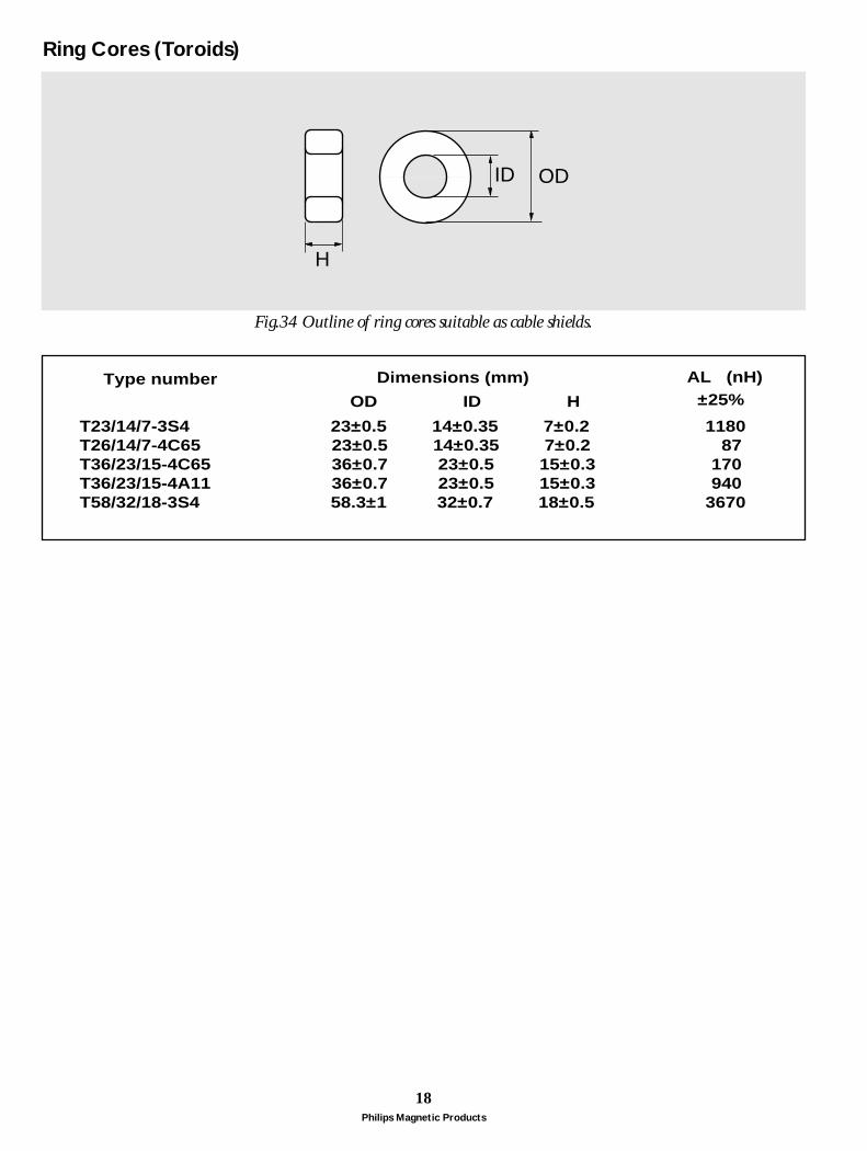
T23/14/7-3S4 23±0.5 14±0.35 7±0.2 1180 T26/14/7-4C65 23±0.5 14±0.35 7±0.2 87 T36/23/15-4C65 36±0.7 23±0.5 15±0.3 170 T36/23/15-4A11 36±0.7 23±0.5 15±0.3 940 T58/32/18-3S4 58.3±1 32±0.7 18±0.5 3670
Type numberOD ID H
Dimensions (mm) AL (nH)±25%
Ring Cores (Toroids)
Fig.34 Outline of ring cores suitable as cable shields.
Philips Magnetic Products
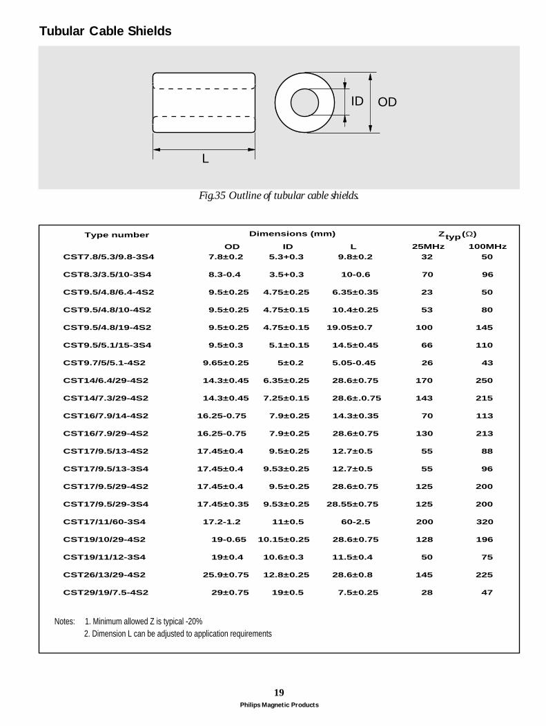
19
ID OD
L
CST7.8/5.3/9.8-3S4 7.8±0.2 5.3+0.3 9.8±0.2 32 50 CST8.3/3.5/10-3S4 8.3-0.4 3.5+0.3 10-0.6 70 96
CST9.5/4.8/6.4-4S2 9.5±0.25 4.75±0.25 6.35±0.35 23 50
CST9.5/4.8/10-4S2 9.5±0.25 4.75±0.15 10.4±0.25 53 80
CST9.5/4.8/19-4S2 9.5±0.25 4.75±0.15 19.05±0.7 100 145
CST9.5/5.1/15-3S4 9.5±0.3 5.1±0.15 14.5±0.45 66 110
CST9.7/5/5.1-4S2 9.65±0.25 5±0.2 5.05-0.45 26 43
CST14/6.4/29-4S2 14.3±0.45 6.35±0.25 28.6±0.75 170 250
CST14/7.3/29-4S2 14.3±0.45 7.25±0.15 28.6±.0.75 143 215
CST16/7.9/14-4S2 16.25-0.75 7.9±0.25 14.3±0.35 70 113
CST16/7.9/29-4S2 16.25-0.75 7.9±0.25 28.6±0.75 130 213
CST17/9.5/13-4S2 17.45±0.4 9.5±0.25 12.7±0.5 55 88 CST17/9.5/13-3S4 17.45±0.4 9.53±0.25 12.7±0.5 55 96 CST17/9.5/29-4S2 17.45±0.4 9.5±0.25 28.6±0.75 125 200
CST17/9.5/29-3S4 17.45±0.35 9.53±0.25 28.55±0.75 125 200
CST17/11/60-3S4 17.2-1.2 11±0.5 60-2.5 200 320
CST19/10/29-4S2 19-0.65 10.15±0.25 28.6±0.75 128 196
CST19/11/12-3S4 19±0.4 10.6±0.3 11.5±0.4 50 75
CST26/13/29-4S2 25.9±0.75 12.8±0.25 28.6±0.8 145 225
CST29/19/7.5-4S2 29±0.75 19±0.5 7.5±0.25 28 47
Type number
OD ID L
Dimensions (mm) Z (Ω)typ25MHz 100MHz
Notes: 1. Minimum allowed Z is typical -20% 2. Dimension L can be adjusted to application requirements
Tubular Cable Shields
Fig.35 Outline of tubular cable shields.
Philips Magnetic Products
20
0
50
100
150
200
250
300
1 10 100 1000f (MHz)
Z (Ω)
CST9.5/4.8/6.4-4S2
CST9.5/4.8/19-4S2
CST9.5/4.8/10-4S2
CST9.7/5/5.1-4S2
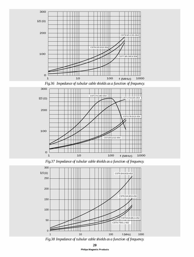
300
0
200
1 10 100 1000
100
f (MHz)
Z (Ω)
CST8.3/3.5/10-3S4
CST9.5/5.1/15-3S4
CST7.8/5.3/9.8-3S4
300
0
200
1 10 100 1000
100
f (MHz)
Z (Ω)CST17/11/60-3S4
CST17/9.5/29-3S4
CST17/9.5/13-3S4
CST19/11/12-3S4
Fig.36 Impedance of tubular cable shields as a function of frequency.
Fig.38 Impedance of tubular cable shields as a function of frequency.
Fig.37 Impedance of tubular cable shields as a function of frequency.
Philips Magnetic Products
21
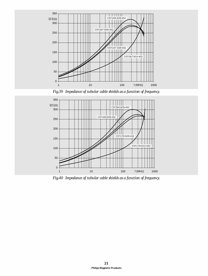
0
50
100
150
200
250
300
350
1 10 100 1000f (MHz)
Z (Ω)
CST17/9.5/29-4S2
CST19/10/29-4S2
CST26/13/29-4S2
CST17/9.5/13-4S2
0
50
100
150
200
250
300
350
1 10 100 1000f (MHz)
Z (Ω) CST14/6.4/29-4S2
CST16/7.9/29-4S2
CST14/7.3/29-4S2
CST16/7.9/14-4S2
Fig.40 Impedance of tubular cable shields as a function of frequency.
Fig.39 Impedance of tubular cable shields as a function of frequency.
Philips Magnetic Products
22
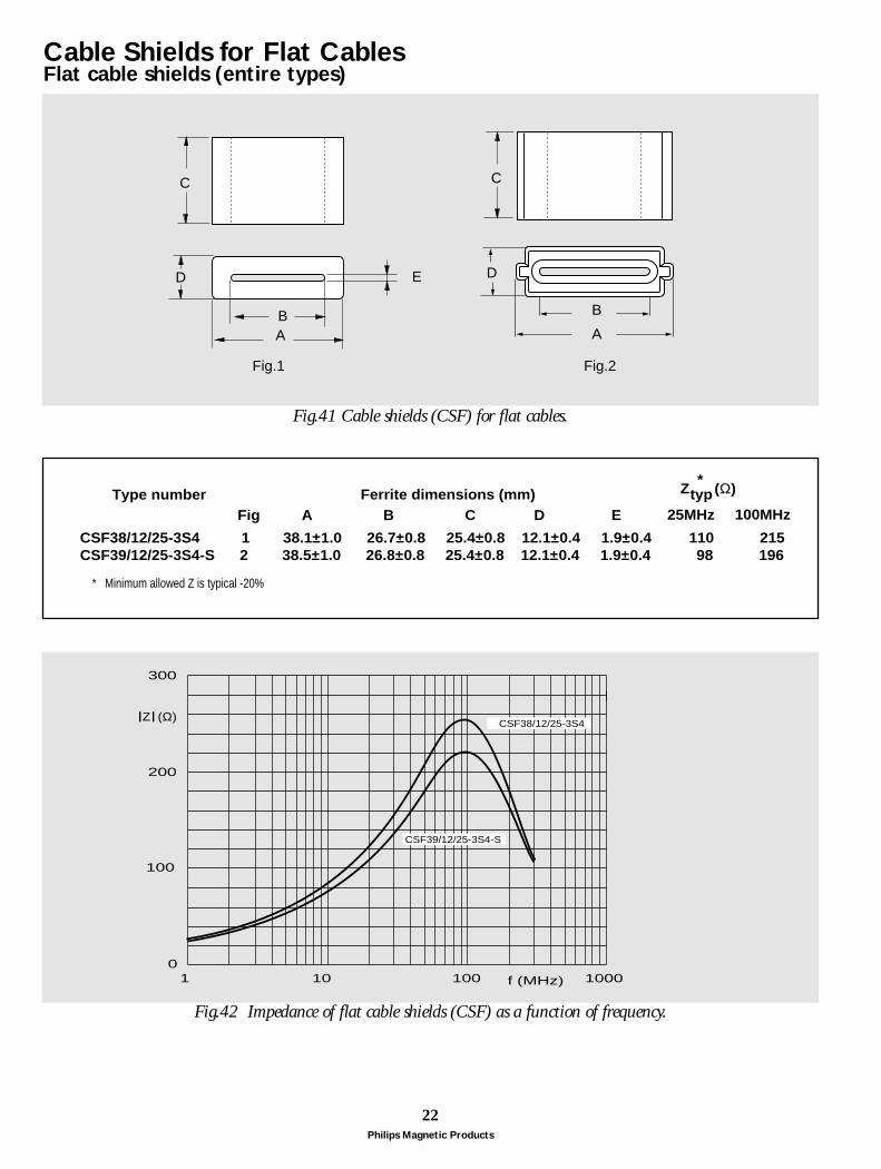
BA
D
C
ED
B
A
C
Fig.1 Fig.2
CSF38/12/25-3S4 1 38.1±1.0 26.7±0.8 25.4±0.8 12.1±0.4 1.9±0.4 110 215 CSF39/12/25-3S4-S 2 - 38.5±1.0 26.8±0.8 25.4±0.8 12.1±0.4 1.9±0.4 98 196
Type numberFig A B C D E
Ferrite dimensions (mm) Z (Ω)typ25MHz 100MHz
*
* Minimum allowed Z is typical -20%
300
0
200
1 10 100 1000
100
f (MHz)
Z (Ω)CSF38/12/25-3S4
CSF39/12/25-3S4-S
Cable Shields for Flat CablesFlat cable shields (entire types)
Fig.42 Impedance of flat cable shields (CSF) as a function of frequency.
Fig.41 Cable shields (CSF) for flat cables.
Philips Magnetic Products
23
Fig. 1 Fig. 2 Fig. 3
AB
D
E
C
B
A
C
E
D
A
B
C
D
E
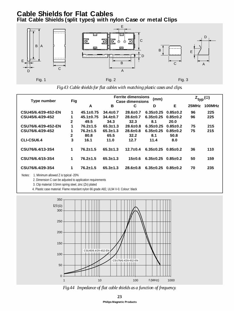
CSU45/6.4/29-4S2-EN 1 45.1±0.75 34.4±0.7 28.6±0.7 6.35±0.25 0.85±0.2 96 225 CSU45/6.4/29-4S2 1 45.1±0.75 34.4±0.7 28.6±0.7 6.35±0.25 0.85±0.2 96 225 2 49.5 34.3 32.3 8.1 20.0 CSU76/6.4/29-4S2-EN 1 76.2±1.5 65.3±1.3 28.6±0.8 6.35±0.25 0.85±0.2 75 215 CSU76/6.4/29-4S2 1 76.2±1.5 65.3±1.3 28.6±0.8 6.35±0.25 0.85±0.2 75 215 2 80.8 65.5 32.2 8.1 50.8 CLI-CSU6.4 3 16.1 11.0 12.7 11.4 8.0
CSU76/6.4/13-3S4 1 76.2±1.5 65.3±1.3 12.7±0.4 6.35±0.25 0.85±0.2 36 110 CSU76/6.4/15-3S4 1 76.2±1.5 65.3±1.3 15±0.6 6.35±0.25 0.85±0.2 50 159
CSU76/6.4/29-3S4 1 76.2±1.5 65.3±1.3 28.6±0.8 6.35±0.25 0.85±0.2 70 235
Type number FigA B C D E
Ferrite dimensions Case dimensions
Z (Ω)typ
25MHz 100MHz
Notes: 1. Minimum allowed Z is typical -20% 2. Dimension C can be adjusted to application requirements 3. Clip material: 0.5mm spring steel, zinc (Zn) plated 4. Plastic case material: Flame retardant nylon 66 grade A82, UL94 V-0. Colour: black
(mm)
0
50
100
150
200
250
300
350
1 10 100 1000f (MHz)
Z (Ω)
CSU45/6.4/29-4S2-EN
CSU76/6.4/29-4S2-EN
Cable Shields for Flat CablesFlat Cable Shields (split types) with nylon Case or metal Clips
Fig.43 Cable shields for flat cables with matching plastic cases and clips.
Fig.44 Impedance of flat cable shields as a function of frequency.
24Philips Magnetic Products
Customized designTo support designers and manufacturers of electronicequipment, PHILIPS COMPONENTS offers itsrecognized know-how. Our staff of application engineersare entirely at your disposal for your comments andinquiries.
Well controlled manufacturing processes, automatedproduction lines and measuring equipment and a longexperience in ferrites make us a flexible, capable andreliable partner.
We are able to give advice, also on custom-designedproducts, either completely new or similar to existing types.
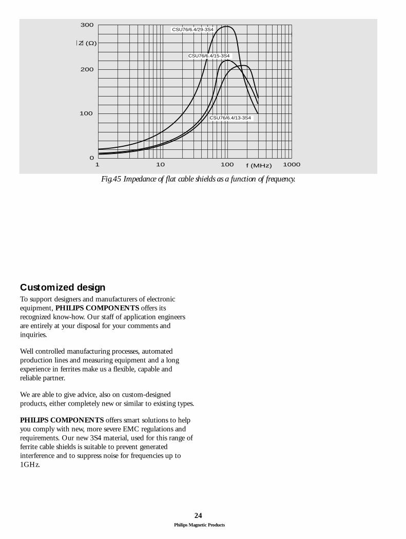
PHILIPS COMPONENTS offers smart solutions to helpyou comply with new, more severe EMC regulations andrequirements. Our new 3S4 material, used for this range offerrite cable shields is suitable to prevent generatedinterference and to suppress noise for frequencies up to1GHz.
300
0
200
1 10 100 1000
100
f (MHz)
Z (Ω)
CSU76/6.4/29-3S4
CSU76/6.4/13-3S4
CSU76/6.4/15-3S4
Fig.45 Impedance of flat cable shields as a function of frequency.
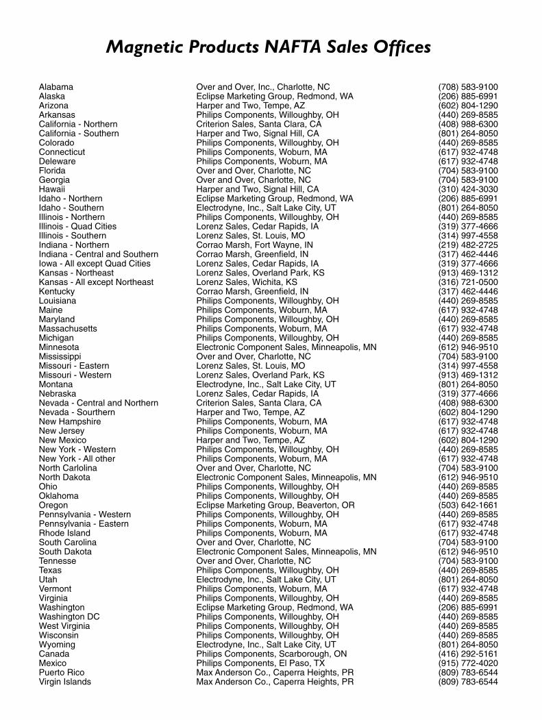
Magnetic Products NAFTA Sales Offices
Alabama Over and Over, Inc., Charlotte, NC (708) 583-9100Alaska Eclipse Marketing Group, Redmond, WA (206) 885-6991Arizona Harper and Two, Tempe, AZ (602) 804-1290Arkansas Philips Components, Willoughby, OH (440) 269-8585California - Northern Criterion Sales, Santa Clara, CA (408) 988-6300California - Southern Harper and Two, Signal Hill, CA (801) 264-8050Colorado Philips Components, Willoughby, OH (440) 269-8585Connecticut Philips Components, Woburn, MA (617) 932-4748Deleware Philips Components, Woburn, MA (617) 932-4748Florida Over and Over, Charlotte, NC (704) 583-9100Georgia Over and Over, Charlotte, NC (704) 583-9100Hawaii Harper and Two, Signal Hill, CA (310) 424-3030Idaho - Northern Eclipse Marketing Group, Redmond, WA (206) 885-6991Idaho - Southern Electrodyne, Inc., Salt Lake City, UT (801) 264-8050Illinois - Northern Philips Components, Willoughby, OH (440) 269-8585Illinois - Quad Cities Lorenz Sales, Cedar Rapids, IA (319) 377-4666Illinois - Southern Lorenz Sales, St. Louis, MO (314) 997-4558Indiana - Northern Corrao Marsh, Fort Wayne, IN (219) 482-2725Indiana - Central and Southern Corrao Marsh, Greenfield, IN (317) 462-4446Iowa - All except Quad Cities Lorenz Sales, Cedar Rapids, IA (319) 377-4666Kansas - Northeast Lorenz Sales, Overland Park, KS (913) 469-1312Kansas - All except Northeast Lorenz Sales, Wichita, KS (316) 721-0500Kentucky Corrao Marsh, Greenfield, IN (317) 462-4446Louisiana Philips Components, Willoughby, OH (440) 269-8585Maine Philips Components, Woburn, MA (617) 932-4748Maryland Philips Components, Willoughby, OH (440) 269-8585Massachusetts Philips Components, Woburn, MA (617) 932-4748Michigan Philips Components, Willoughby, OH (440) 269-8585Minnesota Electronic Component Sales, Minneapolis, MN (612) 946-9510Mississippi Over and Over, Charlotte, NC (704) 583-9100Missouri - Eastern Lorenz Sales, St. Louis, MO (314) 997-4558Missouri - Western Lorenz Sales, Overland Park, KS (913) 469-1312Montana Electrodyne, Inc., Salt Lake City, UT (801) 264-8050Nebraska Lorenz Sales, Cedar Rapids, IA (319) 377-4666Nevada - Central and Northern Criterion Sales, Santa Clara, CA (408) 988-6300Nevada - Sourthern Harper and Two, Tempe, AZ (602) 804-1290New Hampshire Philips Components, Woburn, MA (617) 932-4748New Jersey Philips Components, Woburn, MA (617) 932-4748New Mexico Harper and Two, Tempe, AZ (602) 804-1290New York - Western Philips Components, Willoughby, OH (440) 269-8585New York - All other Philips Components, Woburn, MA (617) 932-4748North Carlolina Over and Over, Charlotte, NC (704) 583-9100North Dakota Electronic Component Sales, Minneapolis, MN (612) 946-9510Ohio Philips Components, Willoughby, OH (440) 269-8585Oklahoma Philips Components, Willoughby, OH (440) 269-8585Oregon Eclipse Marketing Group, Beaverton, OR (503) 642-1661Pennsylvania - Western Philips Components, Willoughby, OH (440) 269-8585Pennsylvania - Eastern Philips Components, Woburn, MA (617) 932-4748Rhode Island Philips Components, Woburn, MA (617) 932-4748South Carolina Over and Over, Charlotte, NC (704) 583-9100South Dakota Electronic Component Sales, Minneapolis, MN (612) 946-9510Tennesse Over and Over, Charlotte, NC (704) 583-9100Texas Philips Components, Willoughby, OH (440) 269-8585Utah Electrodyne, Inc., Salt Lake City, UT (801) 264-8050Vermont Philips Components, Woburn, MA (617) 932-4748Virginia Philips Components, Willoughby, OH (440) 269-8585Washington Eclipse Marketing Group, Redmond, WA (206) 885-6991Washington DC Philips Components, Willoughby, OH (440) 269-8585West Virginia Philips Components, Willoughby, OH (440) 269-8585Wisconsin Philips Components, Willoughby, OH (440) 269-8585Wyoming Electrodyne, Inc., Salt Lake City, UT (801) 264-8050Canada Philips Components, Scarborough, ON (416) 292-5161Mexico Philips Components, El Paso, TX (915) 772-4020Puerto Rico Max Anderson Co., Caperra Heights, PR (809) 783-6544Virgin Islands Max Anderson Co., Caperra Heights, PR (809) 783-6544

PhilipsComponents
Philips Components – a worldwide companyAustralia: Philips Components Pty Ltd., NORTH RYDE,
Tel. +61 2 9805 4455, Fax. +61 2 9805 4466
Austria: Österreichische Philips Industrie GmbH, WIEN,Tel. +43 1 60 101 12 41, Fax. +43 1 60 101 12 11
Belarus: Philips Office Belarus, MINSK,Tel. +375 172 200 924/733, Fax. +375 172 200 773
Benelux: Philips Nederland B.V., EINDHOVEN, NL,Tel. +31 40 2783 749, Fax. +31 40 2788 399
Brazil: Philips Components, SÃO PAULO,Tel. +55 11 821 2333, Fax. +55 11 829 1849
Canada: Philips Electronics Ltd., SCARBOROUGH,Tel. +1 416 292 5161, Fax. +1 416 754 6248
China: Philips Company, SHANGHAI,Tel. +86 21 6354 1088, Fax. +86 21 6354 1060
Denmark: Philips Components A/S, COPENHAGEN S,Tel. +45 32 883 333, Fax. +45 31 571 949
Finland: Philips Components, ESPOO,Tel. +358 9 615 800, Fax. +358 9 615 80510
France: Philips Composants, SURESNES,Tel. +33 1 4099 6161, Fax. +33 1 4099 6493
Germany: Philips Components GmbH, HAMBURG, Tel. +49 40 2489-0, Fax. +49 40 2489 1400
Greece: Philips Hellas S.A., TAVROS,Tel. +30 1 4894 339/+30 1 4894 239, Fax. +30 1 4814 240
Hong Kong: Philips Hong Kong, KOWLOON,Tel. +852 2784 3000, Fax. +852 2784 3003
India: Philips India Ltd., MUMBAI,Tel. +91 22 4930 311, Fax. +91 22 4930 966/4950 304
Indonesia: P.T. Philips Development Corp., JAKARTA,Tel. +62 21 794 0040, Fax. +62 21 794 0080
Ireland: Philips Electronics (Ireland) Ltd., DUBLIN,Tel. +353 1 7640 203, Fax. +353 1 7640 210
Israel: Rapac Electronics Ltd., TEL AVIV,Tel. +972 3 6450 444, Fax. +972 3 6491 007
Italy: Philips Components S.r.l., MILANO,Tel. +39 2 6752 2531, Fax. +39 2 6752 2557
Japan: Philips Japan Ltd., TOKYO,Tel. +81 3 3740 5135, Fax. +81 3 3740 5035
Korea (Republic of): Philips Electronics (Korea) Ltd., SEOUL,Tel. +82 2 709 1472, Fax. +82 2 709 1480
Malaysia: Philips Malaysia SDN Berhad,Components Division, PULAU PINANG, Tel. +60 3 750 5213, Fax. +60 3 757 4880
Mexico: Philips Components, EL PASO, U.S.A.,Tel. +52 915 772 4020, Fax. +52 915 772 4332
New Zealand: Philips New Zealand Ltd., AUCKLAND,Tel. +64 9 815 4000, Fax. +64 9 849 7811
Norway: Norsk A/S Philips, OSLO,Tel. +47 22 74 8000, Fax. +47 22 74 8341
Pakistan: Philips Electrical Industries of Pakistan Ltd., KARACHI,Tel. +92 21 587 4641-49, Fax. +92 21 577 035/+92 21 587 4546
Philippines: Philips Semiconductors Philippines Inc., METRO MANILA, Tel. +63 2 816 6345, Fax. +63 2 817 3474
Poland: Philips Poland Sp. z.o.o., WARSZAWA,Tel. +48 22 612 2594, Fax. +48 22 612 2327
Portugal: Philips Portuguesa S.A.,Philips Components: LINDA-A-VELHA, Tel. +351 1 416 3160/416 3333, Fax. +351 1 416 3174/416 3366
Russia: Philips Russia, MOSCOW,Tel. +7 95 755 6918, Fax. +7 95 755 6919
Singapore: Philips Singapore Pte Ltd., SINGAPORE,Tel. +65 350 2000, Fax. +65 355 1758
South Africa: S.A. Philips Pty Ltd., JOHANNESBURG,Tel. +27 11 470 5911, Fax. +27 11 470 5494
Spain: Philips Components, BARCELONA,Tel. +34 93 301 63 12, Fax. +34 93 301 42 43
Sweden: Philips Components AB, STOCKHOLM,Tel. +46 8 5985 2000, Fax. +46 8 5985 2745
Switzerland: Philips Components AG, ZÜRICH,Tel. +41 1 488 22 11, Fax. +41 1 481 7730
Taiwan: Philips Taiwan Ltd., TAIPEI,Tel. +886 2 2134 2900, Fax. +886 2 2134 2929
Thailand: Philips Electronics (Thailand) Ltd., BANGKOK, Tel. +66 2 745 4090, Fax. +66 2 398 0793
Turkey: Türk Philips Ticaret A.S., GÜLTEPE/ISTANBUL,Tel. +90 212 279 2770, Fax. +90 212 282 6707
United Kingdom: Philips Components Ltd., DORKING,Tel. +44 1306 512 000, Fax. +44 1306 512 345
United States:
• Display Components, ANN ARBOR, MI,Tel. +1 734 996 9400, Fax. +1 734 761 2776
• Magnetic Products, SAUGERTIES, NY,Tel. +1 914 246 2811, Fax. +1 914 246 0487
• Passive Components, SAN JOSE, CA,Tel. +1 408 570 5600, Fax. +1 408 570 5700
Yugoslavia (Federal Republic of): Philips Components, BELGRADE,Tel. +381 11 625 344/373, Fax. +381 11 635 777
Internet:
• Display Components: www.dc.comp.philips.com• Passive Components: www.passives.comp.philips.com
For all other countries apply to: Philips Components, Building BF-1, P.O. Box 218, 5600 MD EINDHOVEN,The Netherlands, Fax. +31-40-27 23 903.
COD19 Ó Philips Electronics N.V. 1998
All rights are reserved. Reproduction in whole or in part is prohibited without theprior written consent of the copyright owner.The information presented in this document does not form part of any quotation orcontract, is believed to be accurate and reliable and may be changed without notice.No liability will be accepted by the publisher for any consequence of its use. Publicationthereof does not convey nor imply any license under patent- or other industrial orintellectual property rights.
Printed in The Netherlands
Document order number: 9398 237 28011 Date of release: 02/97