Embed Size (px)
Citation preview
Cable Specifications and Information
This appendix provides the connector and pinout information you need for making or purchasing cables usedwith the Cisco VG310 and the Cisco VG320 voice gateways. To order cables from Cisco, see ObtainingTechnical Assistance.
This appendix contains the following sections:
• Console and Auxiliary Port Signals and Pinouts, page 1
• Console Port Signals and Pinouts, page 2
• Auxiliary Port Signals and Pinouts, page 3
• Console Port to ASCII Terminal, page 4
• Gigabit Ethernet Connector Pinouts (RJ-45), page 5
• ISDN BRI Interface, page 6
• Analog Voice RJ-21 Pinouts, page 9
• Serial Connection Signals and Pinouts, page 11
• USB Type A-to-USB 5-Pin Mini Type B Cable, page 14
Console and Auxiliary Port Signals and PinoutsCisco VG310 and Cisco VG320 comewith the cable and adapters you need to connect a PC, an ASCII terminal,or a modem to your Cisco VG310 or Cisco VG320.
The cable kit includes:
• RJ-45-to-RJ-45 rollover cable
• RJ-45-to-DB-9 adapter cable for console connection
• DB-9-to-DB-25 adapter cable for modem connection
The console port is configured as data communications equipment (DCE), and the auxiliary port is configuredas data terminal equipment (DTE). Both are asynchronous serial ports and use RJ-45 connectors.
Cisco VG310 and Cisco VG320 Voice Gateways Hardware Installation Guide OL-31292-01 1
Console Port Signals and PinoutsUse the thin, flat, RJ-45-to-RJ-45 rollover cable and RJ-45-to-DB-9 female DTE adapter (labeled TERMINAL)to connect the console port to a PC-running terminal-emulation software. Figure 20 shows how to connectthe console port to a PC. The following table lists the pinouts for the asynchronous serial console port, theRJ-45-to-RJ-45 rollover cable, and the RJ-45-to-DB-9 female DTE adapter (labeled TERMINAL).
Table 1: Console Port Signaling and Cabling Using a DB-9 Adapter
Console DeviceRJ-45-to-DB-9Console DeviceTerminal Adapter(connected toRollover Cable)
RJ-45-to-RJ-45 Rollover CableConsole Port (DTE)
SignalDB-9 PinRJ-45 PinRJ-45 PinSignal
CTS8811RTS
DSR672DTR
RXD263TXD
GND554GND
GND545GND
TXD336RXD
DTR427DSR
RTS718CTS
1 Pin 1 is connected internally to pin 8.
The following table lists the pinouts for the asynchronous serial console port, the RJ-45-to-RJ-45 rollovercable, and the RJ-45-to-DB-25 female DTE adapter (labeled TERMINAL).
Table 2: Console Port Signaling and Cabling Using a DB-25 Adapter
Console DeviceRJ-45-to-DB-25Terminal Adapter
RJ-45-to-RJ-45 Rollover CableConsole Port (DTE)
SignalDB-25 PinRJ-45 PinRJ-45 PinSignal
CTS5811RTS
DSR672DTR
Cisco VG310 and Cisco VG320 Voice Gateways Hardware Installation Guide2 OL-31292-01
Cable Specifications and InformationConsole Port Signals and Pinouts
Console DeviceRJ-45-to-DB-25Terminal Adapter
RJ-45-to-RJ-45 Rollover CableConsole Port (DTE)
RXD363TXD
GND754GND
GND745GND
TXD236RXD
DTR2027DSR
RTS418 2CTS
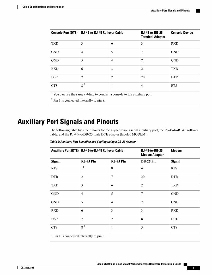
1 You can use the same cabling to connect a console to the auxiliary port.2 Pin 1 is connected internally to pin 8.
Auxiliary Port Signals and PinoutsThe following table lists the pinouts for the asynchronous serial auxiliary port, the RJ-45-to-RJ-45 rollovercable, and the RJ-45-to-DB-25 male DCE adapter (labeled MODEM).
Table 3: Auxiliary Port Signaling and Cabling Using a DB-25 Adapter
ModemRJ-45-to-DB-25Modem Adapter
RJ-45-to-RJ-45 Rollover CableAuxiliary Port (DTE)
SignalDB-25 PinRJ-45 PinRJ-45 PinSignal
RTS4811RTS
DTR2072DTR
TXD263TXD
GND754GND
GND745GND
RXD336RXD
DCD827DSR
CTS518 1CTS
1 Pin 1 is connected internally to pin 8.
Cisco VG310 and Cisco VG320 Voice Gateways Hardware Installation Guide OL-31292-01 3
Cable Specifications and InformationAuxiliary Port Signals and Pinouts
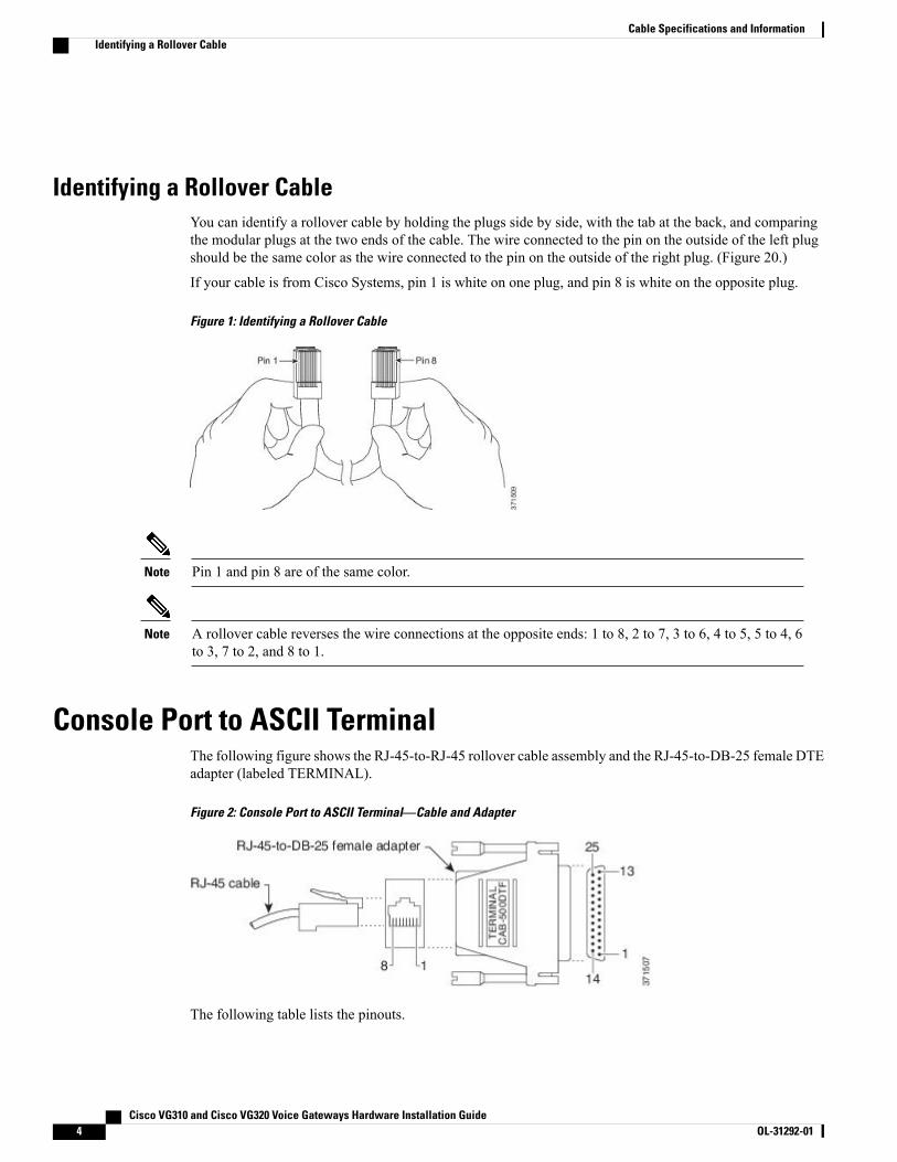
Identifying a Rollover CableYou can identify a rollover cable by holding the plugs side by side, with the tab at the back, and comparingthe modular plugs at the two ends of the cable. The wire connected to the pin on the outside of the left plugshould be the same color as the wire connected to the pin on the outside of the right plug. (Figure 20.)
If your cable is from Cisco Systems, pin 1 is white on one plug, and pin 8 is white on the opposite plug.
Figure 1: Identifying a Rollover Cable
Pin 1 and pin 8 are of the same color.Note
A rollover cable reverses the wire connections at the opposite ends: 1 to 8, 2 to 7, 3 to 6, 4 to 5, 5 to 4, 6to 3, 7 to 2, and 8 to 1.
Note
Console Port to ASCII TerminalThe following figure shows the RJ-45-to-RJ-45 rollover cable assembly and the RJ-45-to-DB-25 female DTEadapter (labeled TERMINAL).
Figure 2: Console Port to ASCII Terminal—Cable and Adapter
The following table lists the pinouts.
Cisco VG310 and Cisco VG320 Voice Gateways Hardware Installation Guide4 OL-31292-01
Cable Specifications and InformationIdentifying a Rollover Cable
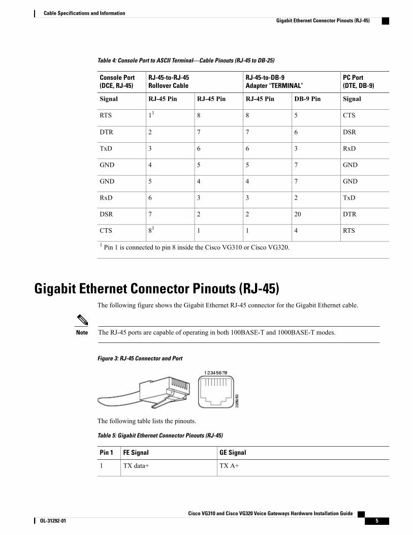
Table 4: Console Port to ASCII Terminal—Cable Pinouts (RJ-45 to DB-25)
PC Port(DTE, DB-9)
RJ-45-to-DB-9Adapter “TERMINAL”
RJ-45-to-RJ-45Rollover Cable
Console Port(DCE, RJ-45)
SignalDB-9 PinRJ-45 PinRJ-45 PinRJ-45 PinSignal
CTS58811RTS
DSR6772DTR
RxD3663TxD
GND7554GND
GND7445GND
TxD2336RxD
DTR20227DSR
RTS41181CTS
1 Pin 1 is connected to pin 8 inside the Cisco VG310 or Cisco VG320.
Gigabit Ethernet Connector Pinouts (RJ-45)The following figure shows the Gigabit Ethernet RJ-45 connector for the Gigabit Ethernet cable.
The RJ-45 ports are capable of operating in both 100BASE-T and 1000BASE-T modes.Note
Figure 3: RJ-45 Connector and Port
The following table lists the pinouts.
Table 5: Gigabit Ethernet Connector Pinouts (RJ-45)
GE SignalFE SignalPin 1
TX A+TX data+1
Cisco VG310 and Cisco VG320 Voice Gateways Hardware Installation Guide OL-31292-01 5
Cable Specifications and InformationGigabit Ethernet Connector Pinouts (RJ-45)
GE SignalFE SignalPin 1
TX A-TX data-2
RX B+RX data+3
TX C+Not used4
TX C-Not used5
RX B–RX data–6
RX D+Not used7
RX D–Not used8
ISDN BRI InterfaceThis section contains the following topics:
• ISDN BRI Connections, on page 6
• ISDN BRI Pinouts, on page 7
• E&M Pinouts, on page 8
Network hazardous voltages are present in the BRI, fractional T1/T1, and switched 56 cables. If you detachthe cable, detach the end away from the router first to avoid possible electric shock. Network hazardousvoltages also are present on the system card in the area of the BRI port (RJ-45 connector), fractional T1/T1port (RJ-48C connector), and switched port (RJ-11 or RJ-48S connector), regardless of when power isturned OFF. Statement 59
Warning
ISDN BRI ConnectionsThe ISDN connection is regarded as a source of voltage that should be inaccessible to user contact. Do notattempt to tamper with or open any public telephone operator (PTO)-provided equipment or connectionhardware. Any hardwired connection (other than by a nonremovable, connect-one-time-only plug) must bemade only by PTO staff or suitably trained engineers. Statement 23BRI WAN interface cards provide ISDN BRI connections. The BRI modules and BRI WAN interface cardsare available with either an S/T interface that requires an external Network Terminator 1 (NT1), or a U interfacethat has a built-in NT1.
Use a BRI cable (not included with...) to connect BRI ports on WAN interface cards (WICs) or on high-speedWICs (HWICs) directly to an ISDN.
Cisco VG310 and Cisco VG320 Voice Gateways Hardware Installation Guide6 OL-31292-01
Cable Specifications and InformationISDN BRI Interface
Hazardous network voltages are present in WAN ports regardless of whether power to the unit is OFF orON. To avoid electric shock, use caution when working near WAN ports. When detaching cables, detachthe end away from the unit first. Statement 1026
Warning
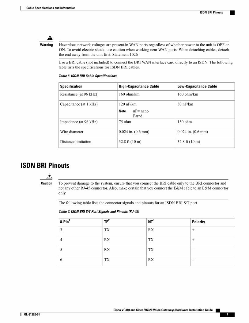
Use a BRI cable (not included) to connect the BRI WAN interface card directly to an ISDN. The followingtable lists the specifications for ISDN BRI cables.
Table 6: ISDN BRI Cable Specifications
Low-Capacitance CableHigh-Capacitance CableSpecification
160 ohm/km160 ohm/kmResistance (at 96 kHz)
30 nF/km120 nF/km
nF= nanoFarad
Note
Capacitance (at 1 kHz)
150 ohm75 ohmImpedance (at 96 kHz)
0.024 in. (0.6 mm)0.024 in. (0.6 mm)Wire diameter
32.8 ft (10 m)32.8 ft (10 m)Distance limitation
ISDN BRI Pinouts
To prevent damage to the system, ensure that you connect the BRI cable only to the BRI connector andnot any other RJ-45 connector. Also, make certain that you connect the E&M cable to an E&M connectoronly.
Caution
The following table lists the connector signals and pinouts for an ISDN BRI S/T port.
Table 7: ISDN BRI S/T Port Signals and Pinouts (RJ-45)
PolarityNT3TE28-Pin1
+RXTX3
+TXRX4
–TXRX5
–RXTX6
Cisco VG310 and Cisco VG320 Voice Gateways Hardware Installation Guide OL-31292-01 7
Cable Specifications and InformationISDN BRI Pinouts

PolarityNT3TE28-Pin1
1 Pins 1, 2, 7, and 8 are not used.2 TE refers to terminal-terminating layer 1 aspects of TE1, TA, and NT functional groups (this applies toISDN BRI S/T WIC).3 NT refers to network-terminating layer 1 aspects of NT1 and NT2 functional groups.
The following table lists the connector signals and pinouts for ISDN BRI U Port Signals and Pinouts (RJ-45).
Table 8: ISDN BRI U Port Signals and Pinouts (RJ-45)
Function8-Pin1
No connection3
Signal—Tip or Ring4
Signal—Tip or Ring5
1 Pins 1, 2, 7, and 8 are not used.
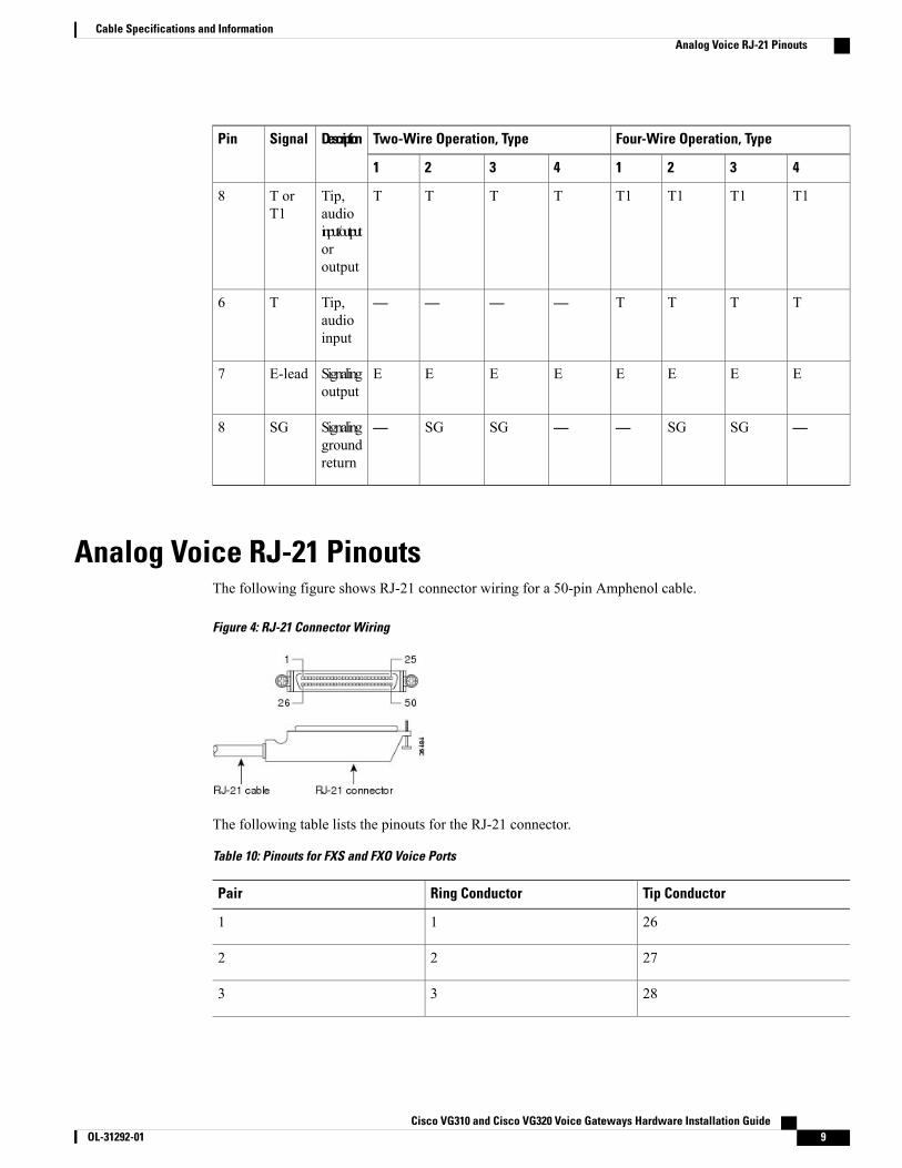
E&M PinoutsThe following table lists the connector signals and pinouts for an E&M port
Table 9: E&M Pinouts
Four-Wire Operation, TypeTwo-Wire Operation, TypeDescriptionSignalPin
43214321
—SBSB———SB—-48Vsignalingbattery
SM1
MMMMMMMMSignalinginput
M-lead2
RRRR————Ring,audioinput
R3
R1R1R1R1RRRRRing,audioinput/outputoroutput
R orR1
4
Cisco VG310 and Cisco VG320 Voice Gateways Hardware Installation Guide8 OL-31292-01
Cable Specifications and InformationE&M Pinouts
Four-Wire Operation, TypeTwo-Wire Operation, TypeDescriptionSignalPin
43214321
T1T1T1T1TTTTTip,audioinput/outputoroutput
T orT1
8
TTTT————Tip,audioinput
T6
EEEEEEEESignalingoutput
E-lead7
—SGSG——SGSG—Signalinggroundreturn
SG8
Analog Voice RJ-21 PinoutsThe following figure shows RJ-21 connector wiring for a 50-pin Amphenol cable.
Figure 4: RJ-21 Connector Wiring
The following table lists the pinouts for the RJ-21 connector.
Table 10: Pinouts for FXS and FXO Voice Ports
Tip ConductorRing ConductorPair
2611
2722
2833
Cisco VG310 and Cisco VG320 Voice Gateways Hardware Installation Guide OL-31292-01 9
Cable Specifications and InformationAnalog Voice RJ-21 Pinouts
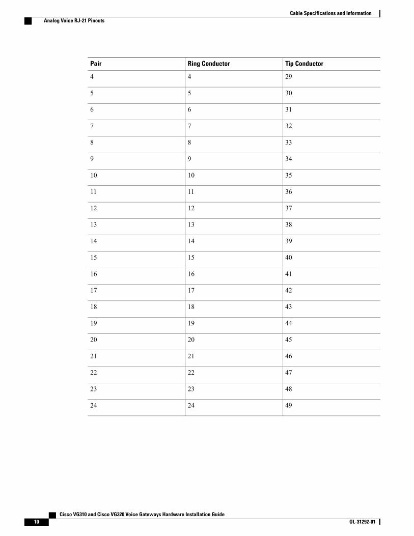
Tip ConductorRing ConductorPair
2944
3055
3166
3277
3388
3499
351010
361111
371212
381313
391414
401515
411616
421717
431818
441919
452020
462121
472222
482323
492424
Cisco VG310 and Cisco VG320 Voice Gateways Hardware Installation Guide10 OL-31292-01
Cable Specifications and InformationAnalog Voice RJ-21 Pinouts
Serial Connection Signals and PinoutsThis section provides information about the 1-port serial WAN interface card (WIC). With the appropriateserial transition cable, thisWIC can provide an EIA/TIA-232, EIA/TIA-449, V.35, X.21, DTE/DCE, EIA-530DTE, or NRZ/NRZI serial interface.
Types of Serial Cables
Five types of serial cables (also called serial adapter cables or serial transition cables) are available from CiscoSystems:
• EIA/TIA-232 Connections, on page 11
• EIA/TIA-449 Connections, on page 12
• V.35 Connections, on page 12
• X.21 Connections, on page 13
• EIA/TIA-530 Connections, on page 13
All serial cables provide a universal plug at theWIC end. The network end of each cable provides the physicalconnectors most commonly used for the interface. For example, the network end of the EIA/TIA-232 serialcable is a DB-25 connector, the most widely used EIA/TIA-232 connector.
All serial interface types except EIA-530 are available in DTE or DCE format: DTE with a plug connector(male) at the network end and DCE with a receptacle (female) at the network end. V.35 is available in eithermode with either gender at the network end. EIA-530 is available in DTE only.
Connecting the WIC to the NetworkThe serial WIC uses a universal high-density, 60-pin receptacle. Each universal port requires a serial portadapter cable that determines the port’s electrical interface type and mode: DTE or DCE. Although all portadapter cables use a universal plug at the serial module end, the network end of each cable type uses thephysical connectors commonly used for the interface. For example, the network end of the EIA/TIA-232 portadapter cable is a DB-25 connector, the most widely used EIA/TIA-232 connector.
After you install the serial WIC, use the appropriate serial cable to connect the WIC DB-60 serial port to oneof the following types of equipment:
• An asynchronous modem if connecting to an analog telephone line.
• A synchronousmodem data service unit/channel service unit (DSU/CSU), or other data circuit-terminatingequipment (DCE), if connecting to a digital WAN line.
EIA/TIA-232 ConnectionsThe EIA/TIA-232 standard supports unbalanced circuits at signal speeds up to 64 kbps.
Cisco VG310 and Cisco VG320 Voice Gateways Hardware Installation Guide OL-31292-01 11
Cable Specifications and InformationSerial Connection Signals and Pinouts
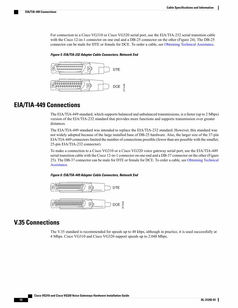
For connection to a Cisco VG310 or Cisco VG320 serial port, use the EIA/TIA-232 serial transition cablewith the Cisco 12-in-1 connector on one end and a DB-25 connector on the other (Figure 24). The DB-25connector can be male for DTE or female for DCE. To order a cable, see Obtaining Technical Assistance.
Figure 5: EIA/TIA-232 Adapter Cable Connectors, Network End
EIA/TIA-449 ConnectionsThe EIA/TIA-449 standard, which supports balanced and unbalanced transmissions, is a faster (up to 2Mbps)version of the EIA/TIA-232 standard that provides more functions and supports transmission over greaterdistances.
The EIA/TIA-449 standard was intended to replace the EIA/TIA-232 standard. However, this standard wasnot widely adopted because of the large installed base of DB-25 hardware. Also, the larger size of the 37-pinEIA/TIA-449 connectors limited the number of connections possible (fewer than are possible with the smaller,25-pin EIA/TIA-232 connector).
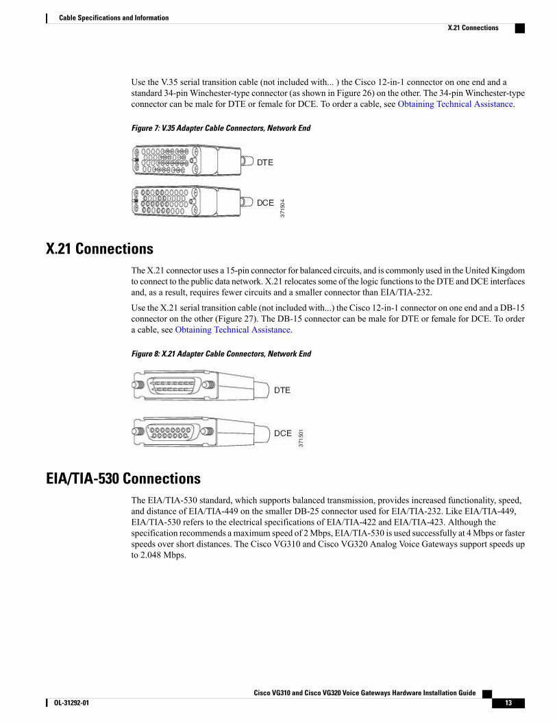
To make a connection to a Cisco VG310 or a Cisco VG320 voice gateway serial port, use the EIA/TIA-449serial transition cable with the Cisco 12-in-1 connector on one end and a DB-37 connector on the other (Figure25). The DB-37 connector can be male for DTE or female for DCE. To order a cable, see Obtaining TechnicalAssistance.
Figure 6: EIA/TIA-449 Adapter Cable Connectors, Network End
V.35 ConnectionsThe V.35 standard is recommended for speeds up to 48 kbps, although in practice, it is used successfully at4 Mbps. Cisco VG310 and Cisco VG320 support speeds up to 2.048 Mbps.
Cisco VG310 and Cisco VG320 Voice Gateways Hardware Installation Guide12 OL-31292-01
Cable Specifications and InformationEIA/TIA-449 Connections
Use the V.35 serial transition cable (not included with... ) the Cisco 12-in-1 connector on one end and astandard 34-pin Winchester-type connector (as shown in Figure 26) on the other. The 34-pin Winchester-typeconnector can be male for DTE or female for DCE. To order a cable, see Obtaining Technical Assistance.
Figure 7: V.35 Adapter Cable Connectors, Network End
X.21 ConnectionsTheX.21 connector uses a 15-pin connector for balanced circuits, and is commonly used in the United Kingdomto connect to the public data network. X.21 relocates some of the logic functions to the DTE and DCE interfacesand, as a result, requires fewer circuits and a smaller connector than EIA/TIA-232.
Use the X.21 serial transition cable (not included with...) the Cisco 12-in-1 connector on one end and a DB-15connector on the other (Figure 27). The DB-15 connector can be male for DTE or female for DCE. To ordera cable, see Obtaining Technical Assistance.
Figure 8: X.21 Adapter Cable Connectors, Network End
EIA/TIA-530 ConnectionsThe EIA/TIA-530 standard, which supports balanced transmission, provides increased functionality, speed,and distance of EIA/TIA-449 on the smaller DB-25 connector used for EIA/TIA-232. Like EIA/TIA-449,EIA/TIA-530 refers to the electrical specifications of EIA/TIA-422 and EIA/TIA-423. Although thespecification recommends a maximum speed of 2Mbps, EIA/TIA-530 is used successfully at 4Mbps or fasterspeeds over short distances. The Cisco VG310 and Cisco VG320 Analog Voice Gateways support speeds upto 2.048 Mbps.
Cisco VG310 and Cisco VG320 Voice Gateways Hardware Installation Guide OL-31292-01 13
Cable Specifications and InformationX.21 Connections
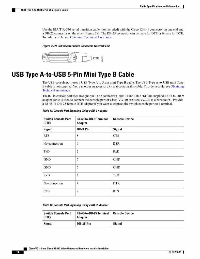
Use the EIA/TIA-530 serial transition cable (not included) with the Cisco 12-in-1 connector on one end anda DB-25 connector on the other (Figure 28). The DB-25 connector can be male for DTE or female for DCE.To order a cable, see Obtaining Technical Assistance.
Figure 9: EIA-530 Adapter Cable Connector, Network End
USB Type A-to-USB 5-Pin Mini Type B CableThe USB console port uses a USB Type A to 5-pin mini Type B cable. The USB Type A-to-USB mini TypeB cable is not supplied. You can order an accessory kit that contains this cable. To order a cable, see ObtainingTechnical Assistance.
The RJ-45 console port uses an eight-pin RJ-45 connector (Table 25 and Table 26). The supplied RJ-45-to-DB-9adapter cable is used to connect the console port of Cisco VG310 or Cisco VG320 to a console PC. Providea RJ-45-to-DB-25 female DTE adapter if you want to connect the switch console port to a terminal.
Table 11: Console Port Signaling Using a DB-9 Adapter
Console DeviceRJ-45-to-DB-9 TerminalAdapter
Switch Console Port(DTE)
SignalDB-9 PinSignal
CTS8RTS
DSR6No connection
RxD2TxD
GND5GND
GND5GND
TxD3RxD
DTR4No connection
RTS7CTS
Table 12: Console Port Signaling Using a DB-25 Adapter
Console DeviceRJ-45-to-DB-25 TerminalAdapter
Switch Console Port(DTE)
SignalDB-25 PinSignal
Cisco VG310 and Cisco VG320 Voice Gateways Hardware Installation Guide14 OL-31292-01
Cable Specifications and InformationUSB Type A-to-USB 5-Pin Mini Type B Cable
Console DeviceRJ-45-to-DB-25 TerminalAdapter
Switch Console Port(DTE)
CTS5RTS
DSR6No connection
RxD3TxD
GND7GND
GND7GND
TxD2RxD
DTR20No connection
RTS4CTS
Cisco VG310 and Cisco VG320 Voice Gateways Hardware Installation Guide OL-31292-01 15
Cable Specifications and InformationUSB Type A-to-USB 5-Pin Mini Type B Cable

Cisco VG310 and Cisco VG320 Voice Gateways Hardware Installation Guide16 OL-31292-01
Cable Specifications and InformationUSB Type A-to-USB 5-Pin Mini Type B Cable


![Terminal de Identificação Biométricovirdi.com.br/pdf/guias/AC-6000_InstGuide_Virdi_pr_pt_A.1.pdf · 7 [R2R]: RS-232 RXD (Entrada) 6 [R2T]: RS-232 TXD (Saída) 5 [G]: GND [Entrada]](https://img.pdfslide.net/doc/110x75/5f818518ab335e355b420743/terminal-de-identificao-biom-7-r2r-rs-232-rxd-entrada-6-r2t-rs-232.jpg)