Embed Size (px)
Citation preview

1 / 14
Document No.PRS-1461
Confidential C © DAI-ICHI SEIKO Co., Ltd. QKE-DFFDE06-08 REV.8
CABLINE® V Connector (Red Phosphorus Free)
Part No. Plug: 20345-#**T-##R Receptacle: 20347-#**E-##R
Product Specification Qualification Test Report No. TR-08068
4 S18670 October 19, 2018 K.Hashimoto H.Ikari 3 S18168 March 7, 2018 K.Ikeshita T.Matsumoto 2 S15560 November 19, 2015 H.Mashima J.Tateishi 1 S13504 December 18, 2013 H.Mashima J.Tateishi E.Kawabe
Rev. ECN Date Prepared by Checked by Approved by

CABLINE® V Connector (Red Phosphorus Free) Document No.
PRS-1461
2 / 14
Confidential C © DAI-ICHI SEIKO Co., Ltd.
1. 序言: CABLINE V コネクタは、コンタクトピッチ 0.4mmで SGC ケーブルならびに Discrete ケーブル用の基板対ワイヤーコネクタである。 (Scope) CABLINE V Connector is wire to board connector for SGC Cable and Discrete cable on pitch of 0.4mm.
2. 目的:本規格は、CABLINE V コネクタの性能と試験条件について規定する。 (Objectives) This specification covers the requirements for product performance and test methods of CABLINEⅤ Connector.
3. 定格 (Ratings) 電流 (Amperage) ・・・・・・・・・・・・・・・・ 0.1A AC/DC [AWG#44] (Per contact / Up to 40 contacts)
0.24A AC/DC [AWG#42] (Per contact / Up to 40 contacts) 0.3A AC/DC [AWG#40] (Per contact / Up to 40 contacts) 0.8A AC/DC [AWG#36] (Per contact / Up to 12 contacts) ※実際の使用状況により温度上昇に影響がありますので、
実機での評価を推奨致します。 ※Testing by a real machine is recommended
because temperature rise may affected by actual situation 電圧 (Voltage) ・・・・・・・・・・・・・・・・・ 100V AC (Per contact)
保管条件 (Storage Condition) : 248~333K (-25℃~+60℃) / 85%RH MAX. / for 1 year ※ 結露無き事。(Non condensing)
使用温度 (Operating Temperature) : 233~358K (-40℃~+85℃) / 85%RH MAX. ※ 通電による温度上昇を含む。
(Containing temperature rise by energizing)
4. 構成、材料及び仕上げ (Construction, Material and Finish) 4.1 プラスチック部品 (Plastic Components)
(1)プラグハウジング (Plug Housing) ・・・・・・・・・・・・・ Heat Resisting Plastics, UL94V-0, Black Red Phosphorus Free
(2)リセプタクルハウジング (Receptacle Housing) ・・・ Heat Resisting Plastics, UL94V-0, Black Red Phosphorus Free
4.2 金属部品 (Metallic Components) (1)プラグ (Plug)
(a) コンタクト (Contact) ・・・・・・・・・・銅合金 (Copper Alloy) メッキ (Plating) ・・・・・・・・Au Plating
(b) シェル A (Shell A) ・・・・・・・・・ステンレス (Stainless steel) or 銅合金 (Copper Alloy) メッキ (Plating) ・・・・・・ ①Sn-Cu Plating ②Sn Plating
(c) シェル B (Shell B) ・・・・・・・・・・・銅合金 (Copper Alloy) メッキ (Plating) ・・・・・・ ①Sn-Cu Plating ②Sn Plating (2)リセプタクル (Receptacle)
(a)コンタクト (Contact) ・・・・・・・・・・ 銅合金 (Copper Alloy) メッキ (Plating) ・・・・・・・ Au Plating
(b)シェル (Shell) ・・・・・・・・・・・・・・・ 銅合金 (Copper Alloy) メッキ (Plating) ・・・・・・ ①Sn-Cu Plating
②Sn Plating

CABLINE® V Connector (Red Phosphorus Free) Document No.
PRS-1461
3 / 14
Confidential C © DAI-ICHI SEIKO Co., Ltd.
5. 試験及び性能 (Test Methods and Performance) : 5.1 試験条件 (Test Condition)
全ての測定と試験は、MIL-STD-202G に基づき以下の条件で行う。 Unless otherwise specified, all tests and measurements shall be performed under the following conditions in accordance with MIL-STD-202G.
温度 (Temperature) ・・・・・・・・・・・・ 288~308K (15~35℃) 湿度 (Humidity) ・・・・・・・・・・・・・・・ 45~75%
気圧 (Atmospheric Pressure) ・・・・ 866~1066hPa (650~800 mmHg)
5.2 試験及び性能 (Test and Performance) 5.2.1 電気的性能 (Electrical)
(1)接触抵抗 (Contact Resistance) A.試験法 ・・・・ テスト基板にリセプタクルコネクタをハンダ付けし、プラグコネクタと嵌合させ、
開回路電圧 20mV DC 以下、短絡電流 1mA DC 以下で4端子法にて芯線 及びシールド線の図1に示す区間の接触抵抗を測定する。 MIL-STD-202G 試験法 307 に準拠。 (Testing) Solder the receptacle connector to the test board and mate the plug connector
together, then measure the contact resistance as shown in Fig.1 by the four terminal method. Apply the low level condition of 20mV MAX. DC for the open circuit voltage and 1mA MAX. DC for the closed circuit current in accordance with MIL-STD-202G, Method 307.
B.必要条件 ・・ 接触抵抗の値は、表1の値を満足すること。 (Requirements) Contact resistance shall meet the values in Table 1.
表(Table)1 接触抵抗 (Contact Resistance)
初期値 (Initial)
Contact AWG#36 ・・・ 235mΩMAX. AWG#40 ・・・ 560mΩMAX. AWG#42 ・・・ 650mΩMAX. AWG#44 ・・・ 1040mΩMAX.
Ground Shell 50mΩ MAX.(Stainless steel)
40mΩ MAX.(Phosphor Bronze)
試験後 (After Testing)
Contact 40mΩ MAX. (ΔR) Ground Shell 40mΩ MAX. (ΔR)
初期値は、ケーブル 100mmの導体抵抗 160mΩ~195mΩ(AWG#36), 485mΩ~520mΩ(AWG#40),
585mΩ~620mΩ(AWG#42), 1000mΩ MAX.(AWG#44) を含む。
Initial contains the conductor resistance 160mΩ~195mΩ(AWG#36), 485mΩ~520mΩ(AWG#40), 585mΩ~620mΩ(AWG#42), 1000mΩMAX.(AWG#44)of a cable 100mm.

CABLINE® V Connector (Red Phosphorus Free) Document No.
PRS-1461
4 / 14
Confidential C © DAI-ICHI SEIKO Co., Ltd.
(2)耐電圧 (Dielectric Withstanding Voltage) A.試験法 ・・・・ リセプタクル及びプラグコネクタを互いに嵌合させ、隣接する端子間及び
端子シールドカバー間に AC 250V(実効値)を一分間印加する。 MIL-STD-202G 試験法 301 に準拠。
(Testing) Mate the receptacle and plug connector together, then apply AC 250V(rms) between the neighboring contacts for a minute in accordance with MIL-STD-202G, Method 301.
B.必要条件 ・・ 沿面放電、空中放電、絶縁破壊等の異常のないこと。 (Requirements) No creeping discharge, flashover, nor insulator breakdown shall occur.
(3)絶縁抵抗 (Insulation Resistance) A.試験法 ・・・・ リセプタクル及びプラグコネクタを互いに嵌合させ、隣接する端子間に DC 500V
を印加し測定する。 MIL-STD-202G 試験法 302 に準拠。
(Testing) Mate the plug and receptacle connector together, then apply DC500V between the neighboring contacts in accordance with MIL-STD-202G, Method 302.
B.必要条件 ・・・・ 初期値は 1000MΩ以上のこと。 試験後は 500MΩ以上のこと。 (Requirements) Insulation resistance shall not be less than 1000MΩ in the initial and 500 MΩ
after testing.
(4)温度上昇(Temperature rising) A.試験法 ・・・・ リセプタクル及びプラグコネクタを互いに嵌合させ、各コンタクトに定格電流を通電
させコネクタ周囲温度上昇を測定する。 (Testing) Mate the plug and receptacle connector together, then apply rating current per contact.
B.必要条件 ・・・・ 温度上昇ΔT:30℃ MAX. (Requirement) ΔT: 30℃ MAX. over ambient.

CABLINE® V Connector (Red Phosphorus Free) Document No.
PRS-1461
5 / 14
Confidential C © DAI-ICHI SEIKO Co., Ltd.
5.2.2 機械的性能 (Mechanical) (1)挿抜力 (Mating/Un-mating Force)
A.試験法 ・・・・ テスト基板にリセプタクルを半田付けする。その後、試料を挿抜試験機に取り付け、 嵌合軸に平行に毎分 25±3mm の速度で、初期及び挿抜 30 回目の挿入抜去力 を測定する。
(Testing) Solder the receptacle connector to the test board, then place the board and plug on push-on/pull-off machine, measure of initial and mating/ un-mating 30th cycles at a
speed 25±3mm/min. along the mating axis.
B.必要条件 ・・ 試験前後の挿入及び抜去力は、表 2 の値を満足すること。 (Requirements) Mating and un-mating force before and after the testing shall meet the values in Table 2.
表(Table)2 挿入抜去力 (Mating/Unmating Force) 挿入力 (Mating Force) 抜去力(Unmating Force)
ロック無し Without Lock
10P 20.0N (2.04kgf) MAX. 2.5N (0.26kgf) MIN.
15P 22.5N (2.30kgf) MAX. 3.0N (0.31kgf) MIN.
20P 25.0N (2.55kgf) MAX. 3.5N (0.36kgf) MIN.
25P 27.5N (2.81kgf) MAX. 4.0N (0.41kgf) MIN.
30P 30.0N (3.06kgf) MAX. 4.5N (0.46kgf) MIN.
35P 32.5N (3.32kgf) MAX. 5.0N (0.51kgf) MIN.
40P 35.0N (3.57kgf) MAX. 5.5N (0.56kgf) MIN.
ロック有り With Lock
10P 20.0N (2.04kgf) MAX. 4.0N (0.41kgf) MIN.
15P 22.5N (2.30kgf) MAX. 5.0N (0.51kgf) MIN.
20P 25.0N (2.55kgf) MAX. 5.5N (0.51kgf) MIN.
25P 27.5N (2.81kgf) MAX. 6.0N (0.61kgf) MIN.
30P 30.0N (3.06kgf) MAX. 7.0N (0.61kgf) MIN.
35P 32.5N (3.32kgf) MAX. 8.0N (0.82kgf) MIN.
40P 35.0N (3.57kgf) MAX. 8.5N (0.82kgf) MIN.
(2)耐久性 (Durability) A.試験法 ・・・・ テスト基板にリセプタクルを半田付けする。その後、試料を挿抜試験機に取り付け、
嵌合軸に平行に毎分 25±3mmの速度で 30 回挿入抜去を行う。 (Testing) Solder the receptacle connector to the test board ,then place the board and plug on
the push-on/pull-off machine ,and repeat mating and un-mating 30 cycles at a speed
25±3mm/min. along the mating axis.
B.必要条件 ・・ 試験前後の接触抵抗は、表 1 の値を満足すること。 (Requirements) Contact resistance before and after the testing shall meet the values in Table 1.

CABLINE® V Connector (Red Phosphorus Free) Document No.
PRS-1461
6 / 14
Confidential C © DAI-ICHI SEIKO Co., Ltd.
(3)端子保持力(Contact Retention Force) A.試験法 ・・・・ コネクタを挿抜試験機に取り付け、毎分 25±3mmの速度で端子の軸に沿って、
端子に圧入と逆方向の荷重を加え、端子がコネクタより抜ける時の荷重を測定する。 (Testing) Place the connector on the push-on/pull-off machine, then apply force on the
contact head and push the contact along the direction opposite to the contact
insertion at a speed of 25±3mm/min. Measure the force when the contact dislodges the connector.
B.必要条件 ・・ プラグの端子保持力は、0.6N (61.2gf) 以上のこと。 リセプタクルの端子保持力は、0.6N ( 61.2gf)以上のこと。 (Requirements) Plug contact retention force shall not be less than 0.6N (61.2gf).
Receptacle contact retention force shall not be less than 0.6N(61.2gf).
(4)ケ-ブル保持力 (Cable Retention Force) A.試験法 ・・・・ プラグコネクタを挿抜試験機に取り付け、毎分 25±3mmの速度で
ケーブル引き出し方向に荷重を加え、断線時の荷重を測定する。 (Testing) Place the plug connector on the push-on/pull-off machine, then apply force
on the cable along the direction at a speed of 25±3mm/min. Measure the force when the cable dislodges the plug connector.
B.必要条件 ・・ ケーブル保持力は、表 3 の値を満足すること。 (Requirements) Cable retention force shall not be less than the values in Table 3.
表(Table)3 ケーブル保持力 (Cable Retention Force) 10P 4.90N (0.50kgf) MIN.
15P 7.35N (0.75kgf) MIN.
20P 9.80N (1.00kgf) MIN.
25P 12.25N (1.25kgf) MIN.
30P 14.70N (1.50kgf) MIN.
35P 17.15N (1.75kgf) MIN.
40P 19.60N (2.00kgf) MIN.
CABLINE® V Connector (Red Phosphorus Free) Document No.
PRS-1461
7 / 14
Confidential C © DAI-ICHI SEIKO Co., Ltd.
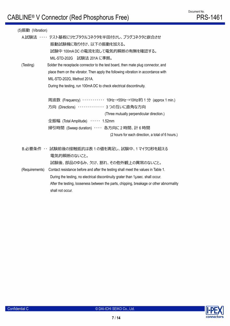
(5)振動 (Vibration) A.試験法 ・・・・ テスト基板にリセプタクルコネクタを半田付けし、プラグコネクタと嵌合させ
振動試験機に取り付け、以下の振動を加える。 試験中 100mA DC の電流を流して電気的瞬断の有無を確認する。 MIL-STD-202G 試験法 201A に準拠。
(Testing) Solder the receptacle connector to the test board, then mate plug connector, and place them on the vibrator. Then apply the following vibration in accordance with MIL-STD-202G, Method 201A. During the testing, run 100mA DC to check electrical discontinuity.
周波数 (Frequency) ・・・・・・・・・・・ 10Hz→55Hz→10Hz/約 1 分 (approx 1 min.) 方向 (Directions) ・・・・・・・・・・・・・ 3 つの互いに直角な方向
(Three mutually perpendicular direction.)
全振幅 (Total Amplitude) ・・・・・ 1.52mm 掃引時間 (Sweep duration) ・・・・ 各方向に 2 時間、計 6 時間
(2 hours for each direction, a total of 6 hours.)
B.必要条件 ・・ 試験前後の接触抵抗は表 1 の値を満足し、試験中、1 マイクロ秒を超える 電気的瞬断のないこと。
試験後、部品のゆるみ、欠け、割れ、その他外観上の異常のないこと。 (Requirements) Contact resistance before and after the testing shall meet the values in Table 1.
During the testing, no electrical discontinuity grater than 1μsec. shall occur. After the testing, looseness between the parts, chipping, breakage or other abnormality
shall not occur.

CABLINE® V Connector (Red Phosphorus Free) Document No.
PRS-1461
8 / 14
Confidential C © DAI-ICHI SEIKO Co., Ltd.
(6)衝撃 (Shock) A.試験法 ・・・・ テスト基板にリセプタクルコネクタを半田付けし、プラグコネクタと嵌合させ
衝撃試験機に取り付け、以下の衝撃を加える。 試験中 100mA DC の電流を流して電気的瞬断の有無を確認する。 MIN-STD-202G 試験法 213B 試験条件 A に準拠。
(Testing) Solder the receptacle connector to the test board, then mate plug connector, and place them on the shock machine. The apply the following shock in accordance with
MIL-STD-202G, Method 213B, Condition A. During the testing run 100mA DC check electrical discontinuity.
最大加速度 (MAX. G) ・・・・・・・・ 50G 標準持続時間 (Duration) ・・・・ 11msec. 波形 (Wave Form) ・・・・・・・・・・ 半波正弦波 (Half Sinusoidal)
B.必要条件 ・・ 試験前後の接触抵抗は表 1 の値を満足し、試験中、1 マイクロ秒を超える 電気的瞬断のないこと。 試験後、部品のゆるみ、欠け、割れ、その他外観上の異常のないこと。
(Requirements) Contact resistance before and after the testing shall meet the values in Table 1.
During the testing, no electrical discontinuity grater than 1μsec. shall occur. After the testing, looseness between the parts, chipping, breakage or other abnormality shall not occur.
5.2.3 耐環境性 (Environmental) (1)熱衝撃 (Thermal Shock)
A.試験法 ・・・・ テスト基板にリセプタクルコネクタを半田付けし、プラグコネクタと嵌合させ、 以下の環境条件に暴露する。 MIL-STD-202G 試験法 107G 試験条件 B に準拠。
(Testing) Solder the receptacle connector to the test board, then mate plug connector, and expose them to the following environment in accordance with MIL-STD-202G, Method 107G, Condition B.
温度 (Temperature) ・・・・・・・・・・ 218K [30 min.] → 358K [30 min.] (-55℃ [30 min.] → +85℃ [30 min.])
移動時間 (Transition time) ・・・・ 5 分 (min.) MAX. 回数 (No. of cycles) ・・・・・・・・・・・ 5 サイクル (cycles)
B.必要条件 ・・ 試験前後の接触抵抗は、表 1 の値を満足すること。 (Requirements) Contact resistance before and after the testing shall meet the values in Table 1.

CABLINE® V Connector (Red Phosphorus Free) Document No.
PRS-1461
9 / 14
Confidential C © DAI-ICHI SEIKO Co., Ltd.
(2)高温寿命 (High Temperature Life) A.試験法 ・・・・ テスト基板にリセプタクルコネクタを半田付けし、プラグコネクタと嵌合させ、
以下の環境条件に暴露する。 MIL-STD-202G 試験法 108A 試験条件 B に準拠。 (Testing) Solder the receptacle connector to the test board, then mate plug connector, and
expose them to the following environment in accordance with MIL-STD-202G, Method 108A, Condition B.
温度 (Temperature) ・・・・ 358±2K (85±2℃) 期間 (Duration) ・・・・・・・ 250 時間 (hours)
B.必要条件 ・・ 試験前後の接触抵抗は、表 1 の値を満足すること。 また、試験前後の端子保持力は、5.2.2.(3)を満足すること。
(Requirements) Contact resistance before and after the testing shall meet the values in Table 1. Contact retention force before and after the testing shall meet 5.2.2.(3).
(3)湿度 (Humidity):定常状態 (Steady State) A.試験法 ・・・・ テスト基板にリセプタクルコネクタを半田付けし、プラグコネクタと嵌合させ、
以下の条件に暴露する。 MIL-STD-202G 試験法 103B 試験条件 A に準拠。 (Testing) Solder the receptacle connector to the test board, then mate plug connector, and
expose them to the following environment in accordance with MIL-STD-202G, Method 103B, Condition A.
温度 (Temperature) ・・・・ 313±2K (40±2℃) 湿度 (Humidity) ・・・・・・・ 90~95%RH 期間 (Duration) ・・・・・・・・ 240 時間 (hours)
B.必要条件 ・・ 試験前後の接触抵抗は表 1 の値を満足し、耐電圧は 5.2.1.(2)を、絶縁抵抗は、 5.2.1.(3)をそれぞれ満足すること。
(Requirements) Contact resistance before and after the testing shall meet the values in Table 1, dielectric withstanding voltage shall meet 5.2.1.(2), insulation resistance
shall meet 5.2.1.(3).
CABLINE® V Connector (Red Phosphorus Free) Document No.
PRS-1461
10 / 14
Confidential C © DAI-ICHI SEIKO Co., Ltd.
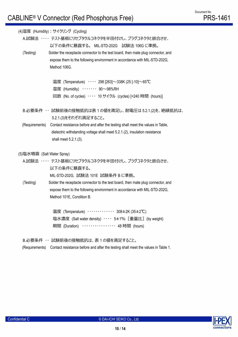
(4)湿度 (Humidity):サイクリング (Cycling) A.試験法 ・・・・ テスト基板にリセプタクルコネクタを半田付けし、プラグコネクタと嵌合させ、
以下の条件に暴露する。 MIL-STD-202G 試験法 106G に準拠。 (Testing) Solder the receptacle connector to the test board, then mate plug connector, and
expose them to the following environment in accordance with MIL-STD-202G, Method 106G.
温度 (Temperature) ・・・・ 298 [263]~338K (25 [-10]~65℃ 湿度 (Humidity) ・・・・・・・ 90~98%RH 回数 (No. of cycles) ・・・・ 10 サイクル (cycles) [=240 時間 (hours)]
B.必要条件 ・・ 試験前後の接触抵抗は表 1 の値を満足し、耐電圧は 5.2.1.(2)を、絶縁抵抗は、 5.2.1.(3)をそれぞれ満足すること。
(Requirements) Contact resistance before and after the testing shall meet the values in Table, dielectric withstanding voltage shall meet 5.2.1.(2), insulation resistance shall meet 5.2.1.(3).
(5)塩水噴霧 (Salt Water Spray) A.試験法 ・・・・ テスト基板にリセプタクルコネクタを半田付けし、プラグコネクタと嵌合させ、
以下の条件に暴露する。 MIL-STD-202G, 試験法 101E 試験条件 B に準拠。
(Testing) Solder the receptacle connector to the test board, then mate plug connector, and expose them to the following environment in accordance with MIL-STD-202G, Method 101E, Condition B.
温度 (Temperature) ・・・・・・・・・・・・・ 308±2K (35±2℃) 塩水濃度 (Salt water density) ・・・・ 5±1%[重量比](by weight) 期間 (Duration) ・・・・・・・・・・・・・・・・ 48 時間 (hours)
B.必要条件 ・・ 試験前後の接触抵抗は、表 1 の値を満足すること。 (Requirements) Contact resistance before and after the testing shall meet the values in Table 1.

CABLINE® V Connector (Red Phosphorus Free) Document No.
PRS-1461
11 / 14
Confidential C © DAI-ICHI SEIKO Co., Ltd.
(6)ガス (Gas): H2S A.試験法 ・・・・ テスト基板にリセプタクルコネクタを半田付けし、プラグコネクタと嵌合させ、
以下の環境条件に暴露する。 (Testing) Solder the receptacle connector to the test board, then mate plug connector, and
expose them to the following environment.
試験槽温度 (Chamber temperature) ・・・ 313±2K (40±2℃) ガス (Gas) ・・・・・・・・・・・・・・・・・・・・・・・・・・・ H2S 3ppm 湿度 (Humidity) ・・・・・・・・・・・・・・・・・・・・・・ 80±5% 期間 (Duration) ・・・・・・・・・・・・・・・・・・・・・・ 96 時間 (hours)
B.必要条件 ・・ 試験前後の接触抵抗は、表 1 の値を満足すること。 また、性能上有害な異常のないこと。
(Requirements) Contact resistance before and after the testing shall meet the values in Table 1. No abnormality adversely affecting the performance shall occur.
5.2.4 その他 (Others) (1)半田付け性 (Solderability)
A.試験法 ・・・・ 端子の半田付け部を 518±5K(245±5℃)の半田槽内に 5±0.5 秒浸す。 フラックスは、RMAまたはR型を使用し 5~10 秒間浸漬するものとする。
(Testing) Dip the solder tine of the contact in the solder bath at 518±5K(245±5℃) for 5±0.5sec. After immersing the tine in the flux of RMA or R type for 5 to 10 seconds.
B.必要条件 ・・ 浸した面線の 95%以上に半田がむらなく付着すること。 (Requirements) More than 95% of the dipped surface shall be evenly wet.
(2)半田耐熱性 (Soldering Heat Resistance) リフロー部 (Reflow)
A.試験法 ・・・・ ①リフロー部 (Reflow part) (Testing) ピーク(Peak) 523~527K (250~255℃)
503K (230℃)MIN. 20~40sec. ②予熱部 (Pre-heat part)
423~453K(150~180℃) 60~120sec. リフロー回数は 2 回以内 (The number of times of Reflow is within 2.) リフロー温度プロファイル参照。 (Refer to Reflow temperature profile)
B.必要条件 ・・ 機能を損なう変形及び欠陥の無いこと。 (Requirements) No abnormality adversely affecting the performance shall occur.

CABLINE® V Connector (Red Phosphorus Free) Document No.
PRS-1461
12 / 14
Confidential C © DAI-ICHI SEIKO Co., Ltd.
手半田 (Soldering iron) A.試験法 ・・・・ 半田こて先温度 (Operating temperature) :613~633K (340~360℃) こて先当て時間 (Application time of soldering iron) :4~6sec. (Testing) 加熱回数 (The number of times of Appliation) : 3 回 B.必要条件・・・ 機能を損なう変形及び欠陥の無いこと。 (Requirements) No abnormality adversely affecting the performance shall occur.
CABLINE® V Connector (Red Phosphorus Free) Document No.
PRS-1461
13 / 14
Confidential C © DAI-ICHI SEIKO Co., Ltd.
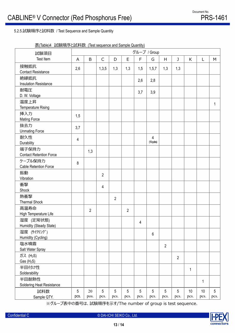
5.2.5.試験順序と試料数 / Test Sequence and Sample Quantity
表(Table)4 試験順序と試料数 (Test sequence and Sample Quantity)
試験項目 Test Item
グループ / Group A B C D E F G H J K L M
接触抵抗 Contact Resistance
2,6 1,3,5 1,3 1,3 1,5 1,5,7 1,3 1,3
絶縁抵抗 Insulation Resistance
2,6 2,8
耐電圧 D. W. Voltage
3,7 3,9
温度上昇 Temperature Rising
1
挿入力 Mating Force
1,5
抜去力 Unmating Force
3,7
耐久性 Durability
4 4 (10cycles)
端子保持力 Contact Retention Force
1,3
ケーブル保持力 Cable Retention Force
8
振動 Vibration
2
衝撃 Shock
4
熱衝撃 Thermal Shock
2
高温寿命 High Temperature Life
2 2
湿度 (定常状態) Humidity (Steady State)
4
湿度 (サイクリング) Humidity (Cycling)
6
塩水噴霧 Salt Water Spray
2
ガス (H2S) Gas (H2S)
2
半田付け性 Solderability
1
半田耐熱性 Soldering Heat Resistance
1
試料数 Sample QTY.
5 pcs.
20 pos.
5 pcs.
5 pcs.
5 pcs.
5 pcs.
5 pcs.
5 pcs.
5 pcs.
10 pcs.
10 pcs.
5 pcs.
※グループ表中の番号は、試験順序を示す/The number of group is test sequence.
CABLINE® V Connector (Red Phosphorus Free) Document No.
PRS-1461
14 / 14
Confidential C © DAI-ICHI SEIKO Co., Ltd.
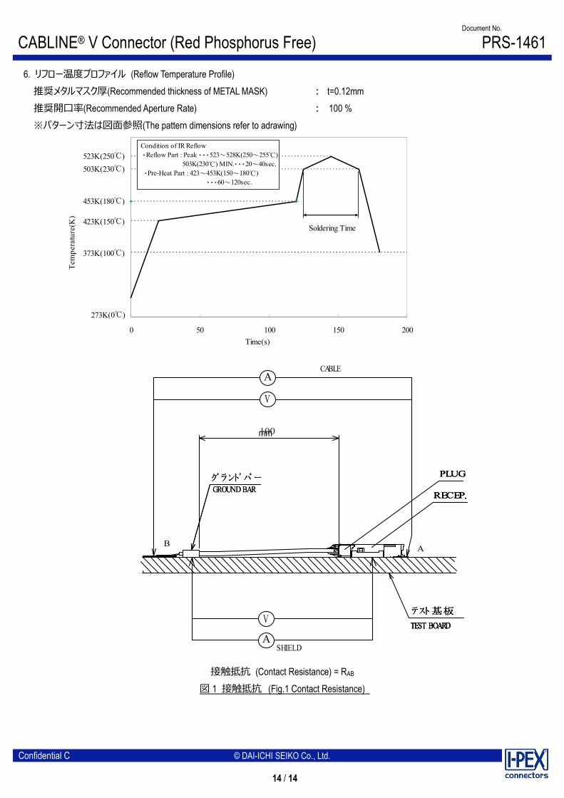
6. リフロー温度プロファイル (Reflow Temperature Profile) 推奨メタルマスク厚(Recommended thickness of METAL MASK) : t=0.12mm 推奨開口率(Recommended Aperture Rate) : 100 % ※パターン寸法は図面参照(The pattern dimensions refer to adrawing)
グ ランド バ ー
A
V
RECEP.
CABLE
グ ランド バ ーGROUND BAR
B A
テスト基板
TEST BOARDV
ASHIELD
PLUG
100
RECEP.
テスト基板
TEST BOARD
PLUGグ ランド バ ーGROUND BAR
RECEP.
テスト基板
TEST BOARD
PLUG
接触抵抗 (Contact Resistance) = RAB
図 1 接触抵抗 (Fig.1 Contact Resistance)
0 50 100 150 200
273K(0℃)
Tem
pera
ture
(K)
Time(s)
Condition of IR Reflow ・Reflow Part : Peak ・・・523~528K(250~255℃) 503K(230℃) MIN.・・・20~40sec. ・Pre-Heat Part : 423~453K(150~180℃) ・・・60~120sec.
Soldering Time423K(150℃)
503K(230℃)523K(250℃)
373K(100℃)
453K(180℃)
mm