Embed Size (px)
DESCRIPTION
final report
Citation preview

CADASTRAL SURVEYING 2
(SUG 519)
NAME: SAFWAN IZZATY BIN SAHARUDDIN
ID NUMBER: 2011923667
LECTURER: PROF. MADYA SR ABDUL RAHMAN BIN ABDUL LATIF
DATE:08 JULY 2013

1.0 GOAL
Working in a group to complete the refixation task.
To strengthen the knowledge of refixation works and applying the theories in the field.
Share knowledge and collaborate in dealing with problems and challenges in the course
of refixation survey.
Practice the field work in accordance with circulars Director General of survey and
mapping.
Practice of recording method using the external workbook.
Practice in computation work.
Practice in computing the offset distance and bearing for refixation.
Familiarize in providing the Calculation Volume (CV) and Certified Plan (CP)
2.0 OBJECTIVE
To describes the purpose and requirements of conducting refixation.
To understand more about the exact terms in the traversing work.
To explain the rules in carrying out the refixation work.
To show the calculation of the external workbook data with the way it has been set up.
To provide the CV and CP in accordance with the prescribed format.

3.0 AREA THE PRACTICAL WAS CONDUCTED
Traversing and refixation work at LOT 28-31, 346-365 Seksyen 2, Bandar Shah Alam, Daerah
Petaling, Selangor Darul Ehsan.
The solar observation was conducted at station 2 besides the lot 364.
Latitude of station 2 : 30 04’ 4.47”

KEY PLAN
The area shaded dark gray
LOCATION PLAN
Seksyen 2, Shah Alam

4.0 INSTRUMENTS USED
Total Station – To measure bearing and distance
Prism – To target the next point
Tripod – To stand the total station and prism at a proper height
Picket – To mark a station that was established

5.0 THEORIES
Refixation is defined as putting back or re-establishing the boundary marks which are out
of position to their original positions. Replacing the boundary marks which are missing or lost or
broken to their original positions based on the refixation calculations.
Two basic assumpations are to be taken into account before starting to refix the boundary
marks; A boundary mark which is found to be upright, firm and projecting at the correct height
above the ground level is assumed to be in its original position until it is proved otherwise; and
the position of the base of a slanting boundary mark must be assumed to be in its original
position until proven otherwise. Therefore, the boundary mark should be set upright to its proper
level before any measurements or observations are taken to or from it.
Refixation is a very costly process and therefore the land surveyor must consider the
following factors before deciding to refix the boundary marks; the amount of displacement, the
location of the land, the value of the land, the effects to the land owner if the boundary mark is
not refixed, the significant of the boundary mark to be used in future datum.
The displacement limits for refixation are as follows;
I. For boundary line less than 40 meters
Bearing not exceeds 01’
Distance not exceeds 0.015m
II. For boundary line more than 40 meters
Bearing not exceeds 30”
Distance not exceeds 0.006m for every 20m with maximum displacement of
0.050m
Criteria have to be considered whether to carry out refixation or not for town, residential,
built up and industrial areas, refixation is required if the displacement is more than 0.050m and
for rural areas where previously second class survey were carried out and for paddy cultivation
areas, refixation is only needed if the displacement exceeds 0.100m
The basic principle in refixation is in computation for refixation, the old values are
adjusted to the new values as the old values physically do not exist. The boundary marks are
placed to its original positions based on offset values computed from nearby traverse stations.
There are exceptional cases for refixation. First for areas which have been previously
surveyed by third class or lower, the boundary marks are accepted as in their original positions
except if there are significant differences with the previous values. Second for areas which have
been previously surveyed by demarcation survey, boundary marks are considered to be in their
original positions provided; for undeveloped areas, boundary marks found in good condition are
considered to be in their original positions, whereas for developed areas, boundary marks found
in good condition are considered to be in their original positions, if they agree with occupation.
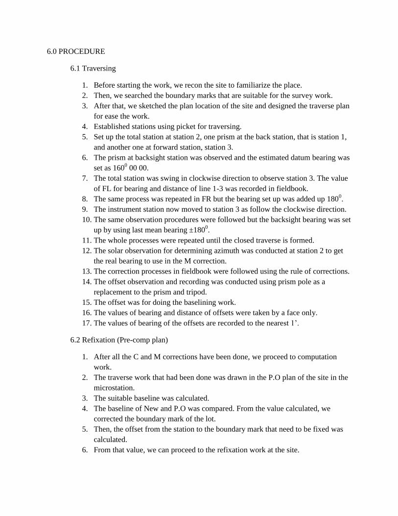
6.0 PROCEDURE
6.1 Traversing
1. Before starting the work, we recon the site to familiarize the place.
2. Then, we searched the boundary marks that are suitable for the survey work.
3. After that, we sketched the plan location of the site and designed the traverse plan
for ease the work.
4. Established stations using picket for traversing.
5. Set up the total station at station 2, one prism at the back station, that is station 1,
and another one at forward station, station 3.
6. The prism at backsight station was observed and the estimated datum bearing was
set as 1600 00 00.
7. The total station was swing in clockwise direction to observe station 3. The value
of FL for bearing and distance of line 1-3 was recorded in fieldbook.
8. The same process was repeated in FR but the bearing set up was added up 1800.
9. The instrument station now moved to station 3 as follow the clockwise direction.
10. The same observation procedures were followed but the backsight bearing was set
up by using last mean bearing ±1800.
11. The whole processes were repeated until the closed traverse is formed.
12. The solar observation for determining azimuth was conducted at station 2 to get
the real bearing to use in the M correction.
13. The correction processes in fieldbook were followed using the rule of corrections.
14. The offset observation and recording was conducted using prism pole as a
replacement to the prism and tripod.
15. The offset was for doing the baselining work.
16. The values of bearing and distance of offsets were taken by a face only.
17. The values of bearing of the offsets are recorded to the nearest 1’.
6.2 Refixation (Pre-comp plan)
1. After all the C and M corrections have been done, we proceed to computation
work.
2. The traverse work that had been done was drawn in the P.O plan of the site in the
microstation.
3. The suitable baseline was calculated.
4. The baseline of New and P.O was compared. From the value calculated, we
corrected the boundary mark of the lot.
5. Then, the offset from the station to the boundary mark that need to be fixed was
calculated.
6. From that value, we can proceed to the refixation work at the site.

6.3 Refixation (on the site)
1. Offset distance less than 1 meter
a. Set total station at a station.
b. Set back bearing to reference station.
c. Open bearing at calculated offset bearing.
d. Plant a picket at station 100 on the offset bearing (about 4m) and measure
the distance.
e. By using another reference station, perform angle and distance checking to
station 100
f. Measure distance from station 100 to the mark to be refixed at.
g. Plant boundary mark according to the distance deduced.
h. Re-measure the distance.
2. Offset distance More than 1 meter
a. Set total station at a station.
b. Set back bearing to reference station.
c. Open bearing at calculated offset bearing.
d. Measure offset distance to the mark to be refixed at and plant the
boundary mark.
e. Perform angle checking to the boundary mark by using another reference
station.
f. Re-measure the distance for checking.
7.0 ACCURACY OF WORK AND PRECAUTION
1. The observations were made in morning and evening day to avoid from the mirage and
the refractive that can produce error. The observation also stop when the weather in the
bad condition to reduce error.
2. The data recorded in the observations were recorded using permanent ink to avoid the
confusion.
3. The reading of the bearing and distance was repeated couple of time to have the mean
value.
4. Explanation of the readings and data were made clearly.
5. The safety of self and instrument are to be priority when doing this observation.

8.0 RESULTS AND ANALYSIS
8.1 Linear Misclosure
Line Bearing Distance Latid Depart
2-3 60 21 06 66.794 33.041 58.049
3-4 44 02 07 79.012 56.803 54.921
4-5 52 27 25 91.846 55.969 72.822
5-6 138 02 41 49.908 -37.115 33.366
6-7 217 55 49 49.136 -38.756 -30.204
7-8 225 05 54 162.212 -114.504 -114.898
8-1 249 27 59 57.413 -20.138 -53.765
1-2 342 35 40 67.795 64.691 -20.280
∑d = 624.116 ∑ = -0.009 ∑ = 0.011
Linear Misclosure = (ℯN)2 + (ℯE)2 = 0.0142
Fractional Linear misclosure = 1 : 44000

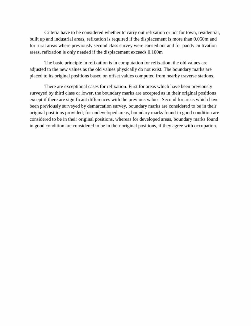
8.2 Baseline
The figure below shows the lot from CP and the new traverse at the site. We decided to choose
line 10 to 15 as the baseline for the refixation as it comply all the requirements as a baseline.
BKL 10 to 15 – Measured 550 40’ 29” 369.017m
PO 550 38’ 45” 368.943m
Correction bearing : +1’44”
Distance : x 1.000m

8.3 Calculation for refixation
Refix at BKB A
Line Distance Bearing Latid Depart
1- 10 7.035 94 21 13 -0.534 7.015
10 - BKB A 20.653 325 16 50 16.976 -11.763
BKB A - 1 16.442 -4.748
Pol(16.442,-4.748)
Distance : 17.114
Bearing : 1630 53’ 34”
Refix at BKB B
Line Distance Bearing Latid Depart
2-1 67.795 162 35 40 -64.691 20.280
1-BKB A 17.114 343 53 34 16.442 -4.748
BKB A - BKB B 51.517 343 06 23 49.294 -14.971
BKB B – 2 1.045 0.561
Pol(1.045,0.561)
Distance : 1.186
Bearing : 208013’44”
2
1
BKB A
BKB 2
1 10
BKB A

Refix at BKB C
Line Distance Bearing Latid Depart
3-2 67.794 240 21 06 -33.041 -58.049
2 – BKB B 1.186 28 13 44 1.045 0.561
BKB B – BKB C 38.950 75 32 50 9.721 37.717
BKB C – 3 -22.275 -19.771
Pol(-22.275,-19.771)
Distance : 29.784
Bearing : 41035’31”
Refix at BKB D
Line Distance Bearing Latid Depart
5-4 91.847 232 27 25 -55.968 -72.825
4-3 79.012 224 02 07 -56.803 -54.921
3-BKB C 29.784 221 35 31 -22.275 -19.771
BKB C- BKB D 199.886 47 55 21 133.951 148.363
BKB D – 5 -1.095 0.846
Pol(-1.095,0.846)
Distance : 1.384
Bearing : 322018’37”
BKB C
BKB D
5
4
3
2
3
BKB B
BKB C

Refix at BKB E
Line Distance Bearing Latid Depart
6-5 49.908 318 02 41 37.115 -33.366
5-BKB D 1.384 142 18 37 -1.095 0.846
BKB D – BKB E 50.158 140 02 33 -38.447 32.212
BKB E – 6 -2.427 -0.308
Pol(-2.427,-0.308)
Distance : 2.446
Bearing : 7013’57”
Refix at BKB F
Line Distance Bearing Latid Depart
8-7 162.212 45 05 54 114.504 114.898
7-6 49.136 37 55 49 38.756 30.204
6-BKB E 2.446 187 13 57 -2.427 -0.308
BKB E-BKB F 208.334 227 25 15 -140.961 -153.405
BKB F-8 9.872 -8.611
Pol(9.872,-8.611)
Distance : 13.100
Bearing : 138054’11”
8
7
6 BKB E
BKB F
5
6
BKB D
BKB E

9.0 CONCLUSION
During the task is carried out, many errors have been made and this things should be
prevented because it will waste time and will corrupted all project of surveying. From this task
we have learn how to reduce the error and the data that we collected was accepted. The result of
the traverse project should be accurate with the small error.
The cooperation and patience of each group members should be praised because without
all of group members’ participation in this project, it could not be successful. If the procedures of
refixation that we have learned are followed, the field work can be done faster and the result will
be accurate.
After this practical was done, I have acquired many lessons in completing a refixation
work. Without the help from the lecturer, we won’t be able to finish this field work completely. I
have learned how to reduce errors in carrying out traverse survey. I went through a lot with my
team. We learn from wrong to right.
10.0 REFERENCES
10.1 Survey regulations 1976
10.2 Peraturan Ukur Kadaster 2002
10.3 Circular Kpup bil. 3/2003

UITM SHAH ALAM
STN BERING JARAK(M) BUKU
KERJA
LUAR
KOORDINAT
U(+)/S(-) T(+)/B(-)
LOT 28-31
LOT 346-
365
2 -11667.59 -21544
3 60 21 06 66.795 -11632.47 -21484
4 44 02 07 79.012 -11574.38 -21426
5 52 27 25 91.846 -11516.92 -21350
6 138 02 41 49.908 -11553.22 -21315
7
8
1
2
217 55 49
225 05 54
249 27 59
323 35 40
49.137
162.212
57.413
67.795
-11591.18
-11703.05
-11722.26
-11666.59
-21344
-21454
-21506
-21544
JUMLAH
624.118
TIKAIAN LURUS 1 : 27898 LUAS = (17028.588 METER PERSEGI)
DIPROSES OLEH : MFNZ TARIKH: 20.06.2013 FAIL UKUR :
P.U.BL.SEL. 39.71
DISEMAK OLEH : IZZATY TARIKH: 29.11.2012 DIUKUR OLEH : SAFWAN
DILULUSKAN OLEH : PROF RAHMAN TARIKH: 29.11.2012
NEGERI : SELANGOR DAERAH: PETALING JAYA MUKIM : SHAH ALAM