Embed Size (px)
Citation preview
3D Plant Design seat
www.cadmatic.com Copyright © CADMATIC, All rights reserved
CADMATIC 3D Plant Design seat is an integrated, database-driven design module and provides powerful tools for 3D layout-, piping-, HVAC-, cable tray- and structural design of plants in shaded and colored views. It produces information for installation and ordering materials.
CADMATIC 3D Plant Design seat 2015Q3
3D Plant Design seat
www.cadmatic.com Copyright © CADMATIC, All rights reserved
CADMATIC 3D Plant Design seat overview
3D Plant Design seat’s unique 3D viewing technique and model database structure keeps the design model extremely light and user friendly even in the biggest and most complicated plant models. Views can be easily configured to allow the best visualization in every possible situation. Various selections of navigation commands and automated routing functions make the 3D modeling the fastest on the market. The online collision control feature alerts the user immediately to clashes during pipe and cable tray routing. The case-based collision control tool applies to any kind of component in the 3D model and enables the user to run separate clash tests at any time. All the collisions are listed and presented via an interactive graphical interface, which makes it easy to fix all the collisions. The accurate 3D model saves a lot of time and money and leads to error free fabrication of pipes and installations in the plant.
3D Plant Design seat automatically assigns a lot of information to all objects in the 3D model and takes care of the concurrent engineering in the project via object ownership control. For example, a routed pipe automatically has information such as flow directions and information about connections, materials, sizes, ownership, etc. All this data is available and can be utilized when creating piping layout drawings, isometric- and spool drawings and material take offs for instance.
Pipe and cable tray routing is specification-driven in CADMATIC 3D Plant Design seat. This rule- based modeling of pipes and cable trays ensures that the correct materials, sizes and components are used during modeling. Desired components can be preselected already in the Diagram module, so the 3D designer automatically receives the correct components in the model via the integration between 3D Plant Design seat and P&ID seat.
3D Plant Design seat provides different kinds of automated pipe routing methods that speed up and ease routing. The designer can for example show only the start and end point for the pipeline and the system creates the whole pipe geometry according predefined settings.
One of the strongest features in CADMATIC 3D Plant Design seat is the ease with which modifications can be made to existing models. Equipment can for example be moved to a new position without losing the connection to pipes, because the system ensures that existing pipe geometries are modified accordingly. This saves a lot of time and effort because re-routing of pipes is not necessary. All kinds of components such as equipment, valves, elbows, etc. can be changed easily one by one or several at a time. This means that 3D design can be started at a very early stage with preliminary components and replaced later with the correct ones with the aid of few mouse clicks.
Documentation such as layout-, piping-, HVAC- and structural drawings can be produced easily. Several automated and semi-automated annotation functions allow the user to create drawing views effectively. Drawings are updated automatically according to the changes made in the 3D model and the revision control tool makes it easy to control the changes between drawing views. Plant modeler supports Windows TrueType Fonts, which makes the appearance of drawings very clear.
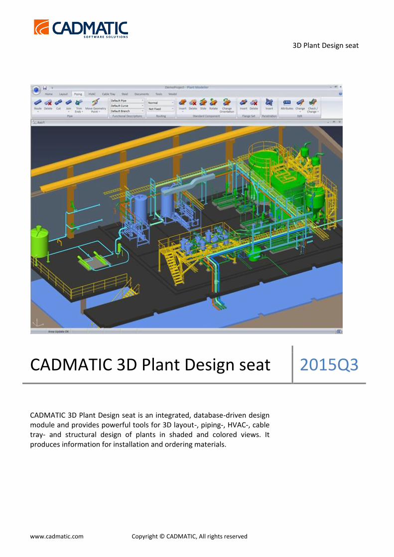
Pic. 1 Detail 3D model view of a paper mill
3D Plant Design seat
www.cadmatic.com Copyright © CADMATIC, All rights reserved
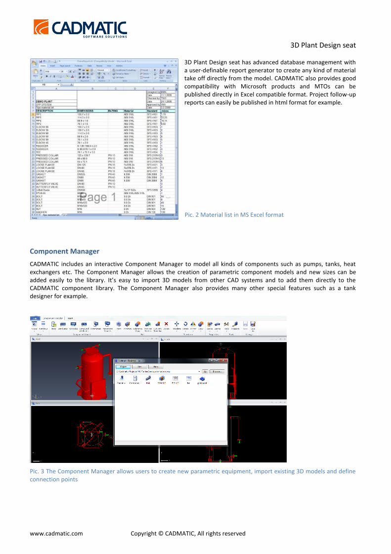
3D Plant Design seat has advanced database management with a user-definable report generator to create any kind of material take off directly from the model. CADMATIC also provides good compatibility with Microsoft products and MTOs can be published directly in Excel compatible format. Project follow-up reports can easily be published in html format for example.
Component Manager
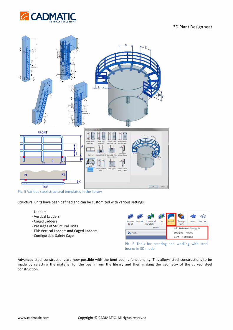
CADMATIC includes an interactive Component Manager to model all kinds of components such as pumps, tanks, heat exchangers etc. The Component Manager allows the creation of parametric component models and new sizes can be added easily to the library. It’s easy to import 3D models from other CAD systems and to add them directly to the CADMATIC component library. The Component Manager also provides many other special features such as a tank designer for example.
Pic. 3 The Component Manager allows users to create new parametric equipment, import existing 3D models and define connection points
Pic. 2 Material list in MS Excel format

3D Plant Design seat
www.cadmatic.com Copyright © CADMATIC, All rights reserved
Integration with P&ID
3D spaces can be used in process diagrams for assigning space information for equipment and armatures. This makes it extremely easy to create preorder lists of materials per zone and estimate the length of the pipes required even before 3D model is created.
The following data is typically shared between the diagram and 3D model: systems and pipelines, equipment, valves, instruments, pipe run topology (order of the elements along pipe run), location information, routes, weight, etc. For electrical diagrams the shared items include cable ids, connections, equipment, cable routes, nodes on cable ways and equipment, locations, as well as compartments, blocks traversed and lengths etc. The topological link between the 2D diagram and 3D model allows the user to benefit from the full integration between the 2D diagram and 3D model. While routing pipes or cables and connecting to equipment, for example, only the correct system and line is suggested to the designer.
Pic. 4 Example of P&ID and 3D model integration
During routing, a “candy bar” visualization indicates the topological route to target the connection, e.g. equipment or switchboard. However, if the designer prefers to change the order of the elements or to connect the pipeline to different pieces of equipment this can be done by simply confirming the action. To detect such cases at a later stage the “compare topology” command can be used. The check will be performed automatically and result in a list of comparison results that allow the user to locate the conflict in the 3D model and decide either to correct it in 2D or 3D. The topological information provided can be used to improve pipe length estimations.
Based on the predefined location of equipment and the topological information the length of pipes and cables can be estimated even before the 3D model is created. This allows designers to estimate the required materials and total cost of the project for the construction and EPCs at an early stage.
Structural design and structural units
CADMATIC 3D Design seat is equipped with all the required tools to create various steel constructions from beams, plates and other materials. The structural units have been developed for fast configurable unit-based modelling of steel constructions such as platforms, railings, stairs, ladders etc. More units are continuously implemented – circular platforms and caged ladders. The user just needs to select the unit type and indicate the location points in the 3D model, after which the steel construction will be created according to the predefined dimensions and components. This functionality further improves the user-friendly and fast modelling tools and saves design time for our customers.
3D Plant Design seat
www.cadmatic.com Copyright © CADMATIC, All rights reserved
Pic. 5 Various steel structural templates in the library
Structural units have been defined and can be customized with various settings:
- Ladders - Vertical Ladders - Caged Ladders - Passages of Structural Units - FRP Vertical Ladders and Caged Ladders - Configurable Safety Cage
Advanced steel constructions are now possible with the bent beams functionality. This allows steel constructions to be made by selecting the material for the beam from the library and then making the geometry of the curved steel construction.
Pic. 6 Tools for creating and working with steel beams in 3D model
3D Plant Design seat
www.cadmatic.com Copyright © CADMATIC, All rights reserved
Using modules and reuse of existing designs
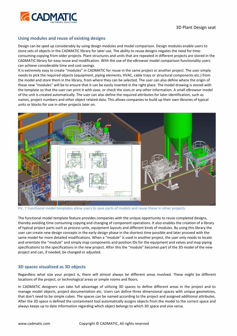
Design can be sped up considerably by using design modules and model comparison. Design modules enable users to store sets of objects in the CADMATIC library for later use. The ability to reuse designs negates the need for time-consuming copying from older projects. Plant structures and units that are repeated in different projects are stored in the CADMATIC library for easy reuse and modification. With the use of the eBrowser model comparison functionality users can achieve considerable time and cost savings. It is extremely easy to create “modules” in CADMATIC for reuse in the same project or another project. The user simply needs to pick the required objects (equipment, piping elements, HVAC, cable trays or structural components etc.) from the model and store them in the library, from where they can be selected. The user can also define where the origin of these new “modules” will be to ensure that it can be easily inserted in the right place. The model drawing is stored with the template so that the user can print it with ease, or check the sizes or any other information. A small eBrowser model of the unit is created automatically. The user can also define the required attributes for later identification, such as names, project numbers and other object related data. This allows companies to build up their own libraries of typical units or blocks for use in other projects later on.
Pic. 7 Functional model templates allow users to save parts of models and reuse these in other projects The functional model template feature provides companies with the unique opportunity to reuse completed designs, thereby avoiding time consuming copying and changing of component operations. It also enables the creation of a library of typical project parts such as process units, equipment layouts and different kinds of modules. By using this library the user can create new design concepts in the early design phase in the shortest time possible and later proceed with the same model for more detailed modifications. When a “module” is used in another project, the user only needs to locate and orientate the “module” and simply map components and position IDs for the equipment and valves and map piping specifications to the specifications in the new project. After this the “module” becomes part of the 3D model of the new project and can, if needed, be changed or adjusted.
3D spaces visualized as 3D objects
Regardless what size your project is, there will almost always be different areas involved. These might be different locations of the project, or technological areas or simple rooms and floors.
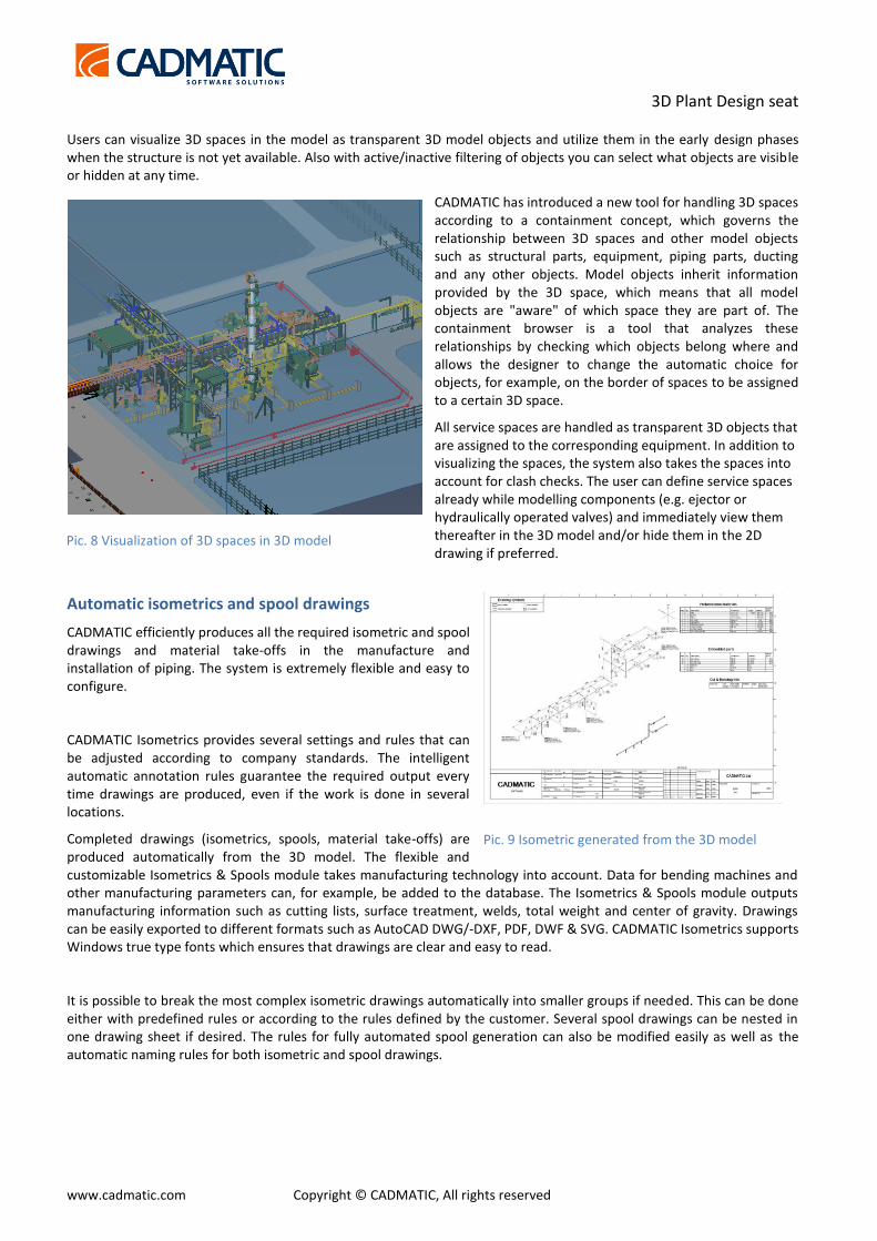
In CADMATIC designers can take full advantage of utilizing 3D spaces to define different areas in the project and to manage model objects, project documentation etc. Users can define three dimensional spaces with unique geometries, that don't need to be simple cubes. The spaces can be named according to the project and assigned additional attributes. After the 3D space is defined the containment tool automatically assigns objects from the model to the correct space and always keeps up to date information regarding which object belongs to which 3D space and vice versa.
3D Plant Design seat
www.cadmatic.com Copyright © CADMATIC, All rights reserved
Users can visualize 3D spaces in the model as transparent 3D model objects and utilize them in the early design phases when the structure is not yet available. Also with active/inactive filtering of objects you can select what objects are visible or hidden at any time.
CADMATIC has introduced a new tool for handling 3D spaces according to a containment concept, which governs the relationship between 3D spaces and other model objects such as structural parts, equipment, piping parts, ducting and any other objects. Model objects inherit information provided by the 3D space, which means that all model objects are "aware" of which space they are part of. The containment browser is a tool that analyzes these relationships by checking which objects belong where and allows the designer to change the automatic choice for objects, for example, on the border of spaces to be assigned to a certain 3D space.
All service spaces are handled as transparent 3D objects that are assigned to the corresponding equipment. In addition to visualizing the spaces, the system also takes the spaces into account for clash checks. The user can define service spaces already while modelling components (e.g. ejector or hydraulically operated valves) and immediately view them thereafter in the 3D model and/or hide them in the 2D drawing if preferred.
Automatic isometrics and spool drawings
CADMATIC efficiently produces all the required isometric and spool drawings and material take-offs in the manufacture and installation of piping. The system is extremely flexible and easy to configure.
CADMATIC Isometrics provides several settings and rules that can be adjusted according to company standards. The intelligent automatic annotation rules guarantee the required output every time drawings are produced, even if the work is done in several locations.
Completed drawings (isometrics, spools, material take-offs) are produced automatically from the 3D model. The flexible and customizable Isometrics & Spools module takes manufacturing technology into account. Data for bending machines and other manufacturing parameters can, for example, be added to the database. The Isometrics & Spools module outputs manufacturing information such as cutting lists, surface treatment, welds, total weight and center of gravity. Drawings can be easily exported to different formats such as AutoCAD DWG/-DXF, PDF, DWF & SVG. CADMATIC Isometrics supports Windows true type fonts which ensures that drawings are clear and easy to read.
It is possible to break the most complex isometric drawings automatically into smaller groups if needed. This can be done either with predefined rules or according to the rules defined by the customer. Several spool drawings can be nested in one drawing sheet if desired. The rules for fully automated spool generation can also be modified easily as well as the automatic naming rules for both isometric and spool drawings.
Pic. 9 Isometric generated from the 3D model
Pic. 8 Visualization of 3D spaces in 3D model
3D Plant Design seat
www.cadmatic.com Copyright © CADMATIC, All rights reserved
One of the most important parts of a design project is the extraction of project documentation. Isometric drawings form a significant part of the documentation scope. Over the years automatic pipe isometric generation was developed as part of CADMATIC software solutions to fulfill the needs of our customers.
The isometric generation module is part of CADMATIC’s solutions and therefore make its use a natural choice. The main goal was to develop an intelligent connection with the 3D model to track all the modifications and accurate annotation mechanism. In replicated projects with several locations and offices working under the same project the software takes care of the ownership
of each isometric drawing and accessibility for all involved engineers.
In big projects piping the number of pipelines can reach several tens of thousands and automatic production of isometrics is critical to keep time schedules and project deadlines.
According to research conducted with our customers, the percentage of isometrics generated fully automatically, without requiring any additional manual work, and ready for printing and workshop, is 98%. Some additional attention might be needed for the rest due to special pipe junctions (e.g. miter elbow connections and the same kind of) that require additional clarification of dimensions on the drawing.
Some of the main advantages of using CADMATIC for isometric generation are the fully customizable layout of isometrics, complete integration with the 3D model, and automatic breaking of isometrics for several pages according to predefined project settings. You can select how big a part of the pipeline will be shown on each page and define how to split pipelines (on flange connections, joints, welding seams etc.). Lists of materials are generated fully automatically
including all kinds of additional materials such as bolts, nuts, washers and insulation materials. Additional information can be easily added to be shown automatically, like coordinates for
installation purposes, labels of next ISOS’ names to continue mounting and external surface area for painting estimation. Additional information can also be imported as referenced drawings that show a 3D picture of the pipeline, or standard projections as well as special sketches for pipe parts.
At the same time when isometric drawings are generated they can be exported in 2D as PDFs, DWGs, DXFs or PCF files, or sent strait to a printer.
The designer can visually control the 3D model piping geometry status in isometric– the comparison mechanism checks updates for piping isometrics and visualizes the differences in a 3D view and in eBrowser.
CADMATIC has a powerful macro language which enables all kinds of scripts to be created by users, such as the customization of production output and automation of design functions for example.
CADMATIC 3D Plant Design seat can be used independently or with the P&ID seat. For more information about the P&ID seat functionality, see the CADMATIC P&ID seat module description.
Pic. 11 Example of symbols, tags, labels and other annotations in an isometric drawing
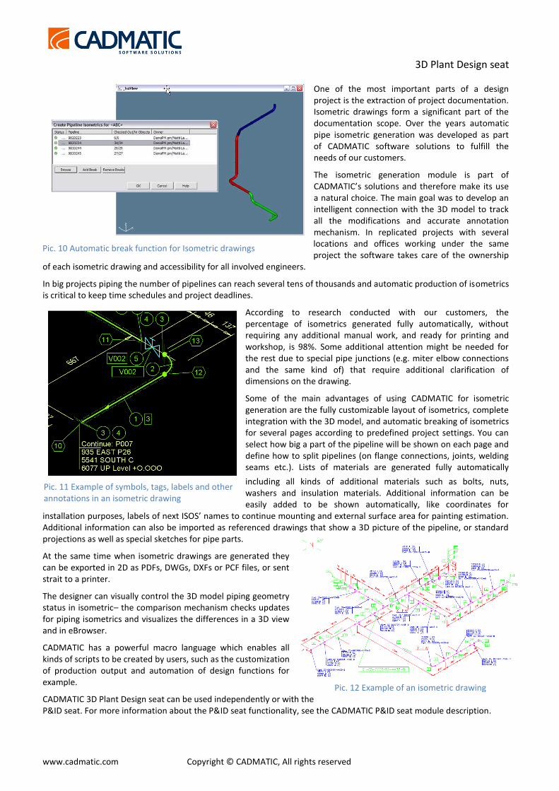
Pic. 10 Automatic break function for Isometric drawings
Pic. 12 Example of an isometric drawing