Embed Size (px)
Citation preview

CADprofi®
User’s manual

We make effort to ensure that information contained in this user manual is accurate and up
to date. However, if you see any mistakes – please let us know, we appreciate any
suggestions.
We reserve the right to make changes in the program. Therefore, there may be slight
discrepancies between this manual and the user program version.
Trademarks
Products listed in this user manual are used only for identification purposes and in most cases
are registered trademarks and are protected by law.
Publication
© CADprofi® – June 2015
All rights reserved. Unauthorized reproduction of this publication in whole form or in
fragments is strictly prohibited.

Table of contents
Page 3
TTaabbllee ooff ccoonntteennttss
Introduction ....................................................................................................................... 9
About the manual ................................................................................................................... 9
About the CADprofi program.................................................................................................. 9
Important information about working with CADprofi .......................................................... 10
Installation ....................................................................................................................... 15
Program installation ............................................................................................................. 15
Online version ...................................................................................................................... 16
Archival versions of CADprofi program ................................................................................ 16
Configuring CADprofi with the CAD program ....................................................................... 17
Registering and activating the license .................................................................................. 19
Network license .................................................................................................................... 21
On-line update ..................................................................................................................... 23
Updating CADprofi program ............................................................................................. 23
Updating multiple seats .................................................................................................... 24
Restore previous version .................................................................................................. 24
CADprofi General commands ............................................................................................ 27
CADprofi – About command ................................................................................................. 27
CADprofi Options .................................................................................................................. 28
Units ................................................................................................................................. 28
Standards.......................................................................................................................... 29
Block layer ........................................................................................................................ 29
Thumbnails ....................................................................................................................... 30
Isometric style .................................................................................................................. 31
Additional options ............................................................................................................ 31
Update options ................................................................................................................. 31
CADprofi layers ..................................................................................................................... 32
Thaw layer groups ............................................................................................................ 33
Table of contents
Page 4
Freeze layer groups .......................................................................................................... 33
Attributes and descriptions .................................................................................................. 34
Frames and tables ................................................................................................................ 37
Numbering ........................................................................................................................... 40
Bill of materials..................................................................................................................... 46
Creating legends and specifications ................................................................................. 52
Creating line and cable specifications............................................................................... 56
Creating specifications of lines, ducts and 2D cable trays ................................................ 57
CADprofi – Tools ................................................................................................................... 59
Delete symbols ................................................................................................................. 59
Quick edition .................................................................................................................... 61
Symbols edition ................................................................................................................ 63
Insert similar object .......................................................................................................... 63
Create alternative view .................................................................................................... 64
Schematic lines – edition .................................................................................................. 66
2D Join pipes/ducts .......................................................................................................... 69
2D Divide pipes/ducts....................................................................................................... 73
2D Edit and info ................................................................................................................ 76
2D Insulation .................................................................................................................... 78
Quick tools........................................................................................................................ 80
Flowcharts and diagrams ..................................................................................................... 81
Diagrams lines .................................................................................................................. 81
Flowcharts, block diagrams .............................................................................................. 82
Manufacturers library .......................................................................................................... 86
Extending program content.................................................................................................. 87
Extending program databases .......................................................................................... 87
Creating and extending user type of series ...................................................................... 88
Defining user blocks ......................................................................................................... 89

Table of contents
Page 5
Editing user block parameters .......................................................................................... 92
CADprofi software translation tutorial ................................................................................. 94
CADprofi context translation ............................................................................................ 95
Export and translation verification ................................................................................... 98
Untranslatable words ..................................................................................................... 103
Special characters ........................................................................................................... 104
CADprofi Architectural .....................................................................................................107
Architectural general commands ....................................................................................... 107
CADprofi Architectural menu and toolbar .......................................................................... 108
CADprofi Architectural – introduction ................................................................................ 109
Drawing walls ..................................................................................................................... 110
Doors, windows .................................................................................................................. 116
Furniture and equipment ................................................................................................... 120
Stairs................................................................................................................................... 124
Roofs .................................................................................................................................. 126
Symbols and marks ............................................................................................................. 127
Level Symbols - automatic .................................................................................................. 128
Level Symbols ..................................................................................................................... 130
Topographic symbols .......................................................................................................... 131
Room definition .................................................................................................................. 132
Architectural dimensioning ................................................................................................ 135
Dimensions ..................................................................................................................... 135
Dimensions editing ......................................................................................................... 139
Dimensions regen ........................................................................................................... 140
Edit extension lines ......................................................................................................... 140
Safety and evacuation symbols .......................................................................................... 141
Evacuation routes ............................................................................................................... 142
CADprofi HVAC & Piping ..................................................................................................147

Table of contents
Page 6
HVAC & Piping general commands ..................................................................................... 147
CADprofi HVAC & Piping menu and toolbar ....................................................................... 148
CADprofi HVAC & Piping – introduction ............................................................................. 149
Schematic lines - general rules ........................................................................................... 149
Pipes/Ducts – scheme ........................................................................................................ 150
Working with symbols – general rules ............................................................................... 163
Symbols .............................................................................................................................. 174
Cross symbols ..................................................................................................................... 177
Multisymbols ...................................................................................................................... 179
Schemes ............................................................................................................................. 183
Marks ................................................................................................................................. 185
Plumbing objects – scheme ................................................................................................ 189
2D views of piping and ventilation installations ................................................................. 191
2D lines and fittings ............................................................................................................ 192
Drawing line sequences ...................................................................................................... 200
Pipe systems ....................................................................................................................... 203
Drawing sewerage installations views ................................................................................ 206
Parametrical armature ....................................................................................................... 208
Parametrical objects ........................................................................................................... 213
Plumbing objects – plan ..................................................................................................... 215
Radiators ............................................................................................................................ 216
Duct devices ....................................................................................................................... 218
Outlets ................................................................................................................................ 220
Supply – air centrals ........................................................................................................... 221
CADprofi Electrical .......................................................................................................... 225
CADprofi Electrical – introduction ...................................................................................... 225
Electrical – general commands ........................................................................................... 226
CADprofi Electrical menu and toolbar ................................................................................ 227

Table of contents
Page 7
Lines, cable trays - scheme ................................................................................................. 228
Working with symbols – general rules ................................................................................ 240
IEC, NFPA symbols .............................................................................................................. 249
Process control symbols ..................................................................................................... 255
Symbols - other .................................................................................................................. 257
PLC controllers.................................................................................................................... 258
Symbols of maps, lines and pillars ...................................................................................... 260
Descriptions ........................................................................................................................ 262
Frames and tables .............................................................................................................. 266
Scheme templates .............................................................................................................. 267
Lighting ............................................................................................................................... 269
Switchgears ........................................................................................................................ 271
Modular units (apparatus) .................................................................................................. 273
Circuits numbering ............................................................................................................. 275
2D Cable trays and ducts .................................................................................................... 280
Drawing tray sequences ..................................................................................................... 286
Drawing mesh trays ............................................................................................................ 289
Designing busbars installations .......................................................................................... 294
CADprofi Mechanical .......................................................................................................299
CADprofi Mechanical – Introduction .................................................................................. 299
Mechanical – general commands ....................................................................................... 299
CADprofi Mechanical menu and toolbar ............................................................................ 300
Standardized parts ............................................................................................................. 301
Steel shapes........................................................................................................................ 306
Exchangers, pipes, fittings .................................................................................................. 309
Symbols and markings ........................................................................................................ 312
Joint symbols .................................................................................................................. 317
Welds views .................................................................................................................... 318

Table of contents
Page 8
Surface roughness .......................................................................................................... 319
Symmetry ....................................................................................................................... 319
Tolerance ........................................................................................................................ 320
Additional markings........................................................................................................ 321
Edges markings ............................................................................................................... 322
Measuring points ............................................................................................................ 322
Projection methods ........................................................................................................ 323
Centre hole ..................................................................................................................... 324
Cone ............................................................................................................................... 324
Cross-sections................................................................................................................. 325
Line break ....................................................................................................................... 326
Fasteners ........................................................................................................................ 327
Fasteners symbols .......................................................................................................... 328
Holes .............................................................................................................................. 329
Technological processes schemes .................................................................................. 329
Hydraulics and pneumatics symbols .................................................................................. 330
Hydraulics and pneumatics lines ........................................................................................ 336
CP–Symbols .................................................................................................................... 343
Introduction ....................................................................................................................... 343
CP-Symbols HVAC & Piping Series ...................................................................................... 344
CP-Symbols Electrical Series ............................................................................................... 345
CP-Symbols Architectural Series ......................................................................................... 346
CP-Symbols Mechanical Series ........................................................................................... 347
Other commands................................................................................................................ 348
CP–Manufacturers........................................................................................................... 351
Introduction ....................................................................................................................... 351
Program commands ........................................................................................................... 351
Information for manufacturers .......................................................................................... 353

Introduction: About the manual
Page 9
IInnttrroodduuccttiioonn
About the manual This manual describes the full functionality of CADprofi® application. We can find in it
description of all commands and dialog windows as well as many useful tips and comments
about using the application. We have also included the most important information required
to properly install and run the program.
About the CADprofi program CADprofi® is a comprehensive CAD application that vastly accelerates the design work in
many branches. CADprofi® Suite program consists of the following modules:
CADprofi® HVAC and Piping
CADprofi® Electrical
CADprofi® Architectural
CADprofi® Mechanical
CP–Symbols program contains a library of symbols from various branches as well
as basic commands that allows editing schemes. The following libraries are
available „HVAC & Piping”, „Electrical”, „Mechanical” and „Architectural”.
CP–Manufacturers program serves as an electronic CAD catalogs that contains
libraries of world known manufacturers. CP-Manufacturers program is being
distributed by manufacturers.
CADprofi program works as an "add-on" on various CAD programs. Therefore, in all
descriptions the "CAD program" should be understood as the AutoCAD®, BricsCAD®,
GstarCAD, IntelliCAD®, progeCAD®, ZWCAD etc. Most commands in these programs work
identical.
Hint
CP-Symbols libraries and CP-Manufacturers catalogs are part of CADprofi® program.
Notice
In AutoCAD® LT, you need to install additional software, such as
LTX ™

Introduction: Important information about working with CADprofi
Page 10
Important information about working with CADprofi Working in CADprofi complies with general rules of designing in CAD programs. The most
important benefit of using CADprofi program is the automation of most activities that are
related to drawing and the comprehensive database of objects and solutions that are ready to
use in your projects.
CADprofi commands have been prepared in such a way that user can work simple and
intuitive even if he hasn't read the manual. However, we encourage reading the manual, so
you will be able to fully use the program's potential.
In order to work comfortably in CADprofi application we recommend familiarizing yourself
with the main program assumptions.
Compatibility with dwg, dxf formats
Project created in CADprofi are ordinary drawings that are saved in dwg or dxf formats. These
drawings can be later edited in CAD programs even without loading the CADprofi add-on.
Many of CADprofi objects are simple blocks that can be exploded and edited using CAD
program standard commands. However, it must be noted that after exploding objects some
properties may be lost and as a result it won't be possible to perform any commands or
create any specifications on these exploded objects.
Standard drawing
For all new drawings, CADprofi inserts definition of layers, text styles, dimension styles and
types of lines saved in a template file. For the appropriate CAD program the template file is
the normal.dwg or normal_ic.dwg files, which are located in the
C:\Cadprofi\X.x\Block\General folder. By editing the template file user can change or expand
the standard definitions of loaded styles.
Notice
C:\CADprofi is a default installation folder of CADprofi program.
This folder may differ if you have selected a different folder during the installation process.

Introduction: Important information about working with CADprofi
Page 11
Drawing scale
All projects should be carried out in a model space with a 1:1 scale in a chosen design unit
(mm, cm, m, and inches).
The target scale specified by user should be determined during the printing or during the
composing of sheets (in the paper space). In some commands it is necessary to provide the scale. Usually this scale is only used to determine the correct text size for printing in a specified scale.
Linetype scale (line density)
It is possible to design in CADprofi in different units (mm, cm, m, and inches). In order to
adjust the line density such as the density of a dashed line, CADprofi will automatically
change the global line density ratio.
The default line density scale is 100 when designing in mm, 10 in cm and 0.1 in m. The default
linetype scale is appropriate for construction and installation projects. In case of mechanical
projects it is often needed to change the linetype scale.
In order to change the linetype scale use the _LTSCALE command. Once the command has
been started, user should enter the required value.
Example of linetype scale change:
Command: ltscale
New current value for LTSCALE <100>: 5
When you run certain commands (in
the mechanical module), CADprofi will
suggest to turn off the automatic
adjustment of linetype scale.
Automatic adjustment of linetype scale
can be turn on again at any time in the
CADprofi Options dialog window.
Layers
In CADprofi Options command user can turn off the automatic management of layers.
However, it is not recommended because some layers properties are dependent on the
objects. For example, when creating BOMs it is possible to automatically select objects from a
particular module (for example all electrical symbols). If the automatic management of layers
option is turned off then it won't be possible to identify symbols of a specific module.
Plot styles that specify the optimal line thickness on the printout are added to CADprofi.
These styles match the automatic layers structure.

Introduction: Important information about working with CADprofi
Page 12
Covering objects (WIPEOUT)
Many CADprofi objects contain covering elements (_WIPEOUT). These elements cover
elements lying underneath. To determine the display order, the CAD program command:
_DRAWORDER (Draw order) should be used.
To correctly print drawings that contain these covered elements, user should properly set
printing options or give a specific color to the CP_WIPEOUT layer.
Standard covers are being displayed without frames. Sometimes however, it may be necessary to
display frames (e.g. to remove or edit the cover). To turn on the frames, it is possible to use the
appropriate option in the _WIPEOUT command.
The coordinate system
Most CADprofi commands can be used in the user coordinate system (UCS). However, some
commands require user to enable the world coordinate system (WCS), which is the default
system in CAD programs.
No dialog windows (for example in the save command)
Some CADprofi commands block the standard dialog windows of CAD programs. After normal
completion of such commands, CADprofi will restore the displaying of dialog windows.
Sometimes user may stop the CADprofi command for example by pressing the Esc key. In
such cases, CADprofi may not restore the dialog windows.
In order to restore the displaying of standard dialog windows user should set the FILEDIA and
CMDDIA variables to 1. To do this, user has to type in the command line the variable name and
set its value to 1.
Command: filedia
New current value for FILEDIA <0>: 1
Command: cmddia
New current value for CMDDIA <0>: 1
User can restore displaying of dialog windows by using the CADprofi Options command.
Toolbars and tool palettes
In CAD programs it is possible to adapt menus and toolbars. Using the CADprofi Configuration
program, CADprofi application can be “attached” or “detached” from the CAD program.
When user attaches CADprofi application to the CAD program, CADprofi standard menu and
toolbars will be loaded. In this case, any changes made to toolbars and menus will be
overwritten. This also applies to tool palettes and CADprofi ribbons.

Introduction: Important information about working with CADprofi
Page 13
Command line
In some CAD programs such as new versions of AutoCAD®, user can disable the command
line. Both CAD programs and CADprofi application display important information in the
command line. For this reason, user should have the command line enabled with at least two
visible lines.
Command line in AutoCAD® program
In AutoCAD® 2006 and later, user can enable the dynamic command line. Dynamic command
line displays only one line and furthermore it may slow the CADprofi application (for example
when editing multiple objects simultaneously). That's why the dynamic line is turned off by
many CADprofi commands.
Dynamic command line in AutoCAD® 2006 program and later
Particularly inconvenient is turning off both classical and dynamic command line. In this case,
user won't be informed about the state of currently processed command.
Expanding libraries and manufacturers' catalogs
It is possible to expand both symbols' and objects' libraries in CADprofi. Once the program
has been installed, it is possible to install new manufacturers' libraries such as those that have
been developed after purchasing CADprofi. Both users' and manufacturers' libraries are saved
in the Producers folder. This folder is located in the main program folder (e.g. C:\Cadprofi). In
order to save all the changes made in the manufacturers' libraries as well as in the user
symbols' and objects' libraries, the Producers folder with all or with selected libraries should
be backed up (archived).
After a program reinstallation or transferring to another computer user can transfer all the
content from the Producers folder to a new installation. It is also possible to copy libraries
within one team of designers (in one company).
User database - UserData folder
In CADprofi program standard databases have been separated from the user databases.
Thanks to this it is possible to update the program without losing the data stored by the user.

Introduction: Important information about working with CADprofi
Page 14
All user data is stored in the UserData folder. This folder is located in the main program folder
(e.g. C:\Cadprofi). In order to save all changes in the user databases, user should archive the
entire UserData folder. After a program reinstallation or transferring to another computer
user can transfer all the content from the UserData folder to a new installation. It is also
possible to copy UserData within one team of designers (for example in a single company).
In CADprofi program user can define various parameters or expand standard databases. It is
possible, for example, to define additional types of installations, additional types of cables
and additional objects' parameters (e.g. price, currency, color, etc.).
This data is stored in the UserData folder.

Installation: Program installation
Page 15
IInnssttaallllaattiioonn The process of creating a CADprofi seat consists of 3 steps: installation, configuration with
your CAD program and license activation.
Program installation After placing the DVD in the disk drive a dialog window will appear allowing you to choose the
language in which the installation will be done.
In order to start the installation wizard choose the CADprofi – Installation item and follow the
prompts.
Selecting components
DVD disk contains all CADprofi modules. During the installation it is possible to install all
CADprofi modules, yet the user must be aware that during the activation he will receive
activation codes only for the purchased modules. Modules, which were not activated, will be
blocked after 30 days from the first program run.
Notice
In order to correctly handle the installation process and program configuration user needs the administrator or power user permission.
CADprofi program allows creating your own libraries, adding your own types of cables etc. This data is stored in different
folders that's why users need to have rights to save and edit files in all folders in which the program is installed. For the same reason it is not recommended to install the program on
the Windows Vista, Windows 7 or later operating systems in the "C: \ Program Files (x86)" and "C: \ Program Files" folders because in those folders the above operating systems are
blocking the possibility to save and edit all files.
Hint
If the start window won’t appear automatically then run the autorun.exe file manually from the Start folder located on the
CADprofi DVD.

Installation: Online version
Page 16
Online version Installation file can be downloaded directly from the CADprofi server. This option is available
when user has purchased the online version.
Installation file with all manufacturers’ libraries has a size of over 1 GB. The name of the file is
for example: „CADprofi_x_full_dvd.exe ".
If the user doesn’t need all libraries he can download a smaller file e.g. „ CADprofi_x.exe”.
After installing CADprofi from this file user will be able to download libraries of selected
manufacturers through an online update system on a later date.
It is necessary to copy the downloaded files to any data storage device such as a DVD disk. In
this way it will be possible to install the program after a computer replacement or a computer
crash.
It is also recommended to archive both Producer and UserData folders in which symbols and
data defined by user are located. Thanks to this, if needed, it will be possible to quickly
restore the whole program content from the backup.
Archival versions of CADprofi program Archival versions of CADprofi software are available on http://www.cadprofi.com website.
CADprofi programs are being covered by a time subscription, so when user downloads the
archive version, he should download the correct one (the one that was published at the time
when user’s subscription was valid).
Notice
If user has downloaded version that had been published after the purchase date or after the subscription expiration date then
he won't be able to activate the program.

Installation: Configuring CADprofi with the CAD program
Page 17
Configuring CADprofi with the CAD program
Automatic configuration of CADprofi with the CAD program
Because CADprofi application works on many CAD programs it is necessary to make the
configuration process. This process is being carried because it is necessary to assign the
CADprofi application to the right environment, which will enable CADprofi to load
automatically after user runs the CAD program.
In order to do this run the CADprofi configuration file, which shortcut has been placed on the
desktop after the installation process.
CADprofi Configuration dialog window
Dialog window contains the following items:
Language – list of available languages in CADprofi software.
Browse manufacturers’ libraries – allows checking the content of manufacturers’ libraries.
Found CAD programs – list of all CAD programs installed on your computer, to which
CADprofi can be automatically configured.
Select CADprofi program – choose which CADprofi application should be configured with the
CAD program.
Check updates – check the availability of a new version via Online update.
Restore CAD – allows to „disconnect” CADprofi application from the selected CAD program
(work without CADprofi).
Configure CAD – configure CADprofi application with the selected CAD program.

Installation: Configuring CADprofi with the CAD program
Page 18
Procedures
Configuring CADprofi with the CAD program
1. Run the Click the CADprofi configuration program that is located on a Windows
desktop. A new dialog window named CADprofi Configuration will appear.
2. Select the language that will be used in the CADprofi program.
3. Select the CAD program on which you want to use CADprofi.
4. Make sure that you have selected CADprofi program. (CP–Manufacturers and
CP–Symbols are used to configure other programs).
5. Click the Configure CAD button in order to start working with CADprofi.
6. (Optional) Application may require to run it with higher rights, and therefore will
require an administration inervention.
7. After a proper configuration a new dialog window will appear asking us if we want
to run the CAD program.
Manual configuration of CADprofi with the CAD program
If the CAD program that you are currently using is not displayed in the CADprofi
Configuration dialog box, then you can perform a "manual" configuration. To make the
process successful we need to be sure that we are using a CAD program that is compatible
with CADprofi. Additional information can be found in the IcadConf.utc file, which is located
in the main CADprofi folder. This file can be opened with any text editor.
Procedures
Manual configuration of CADprofi with the CAD program
1. Adding CADprofi folder to a support file search path.
To the list of support file search path in the CAD program add the location of main
CADprofi folder such as C:\Cadprofi\X.x. In most CAD programs this list is
supported by a SRCHPATH variable or with the Options command.
2. Loading the right CADprofi menu file.
With the _MENULOAD or _CUILOAD command load the appropriate CADprofi mnu or
cui file.
3. Loading the application (the appropriate executable file) and adding it to the
start list.
With the _APPLOAD command load the appropriate executable file (dll, brx, zrx, grx,
arx or other). If we want it to work after each time we run the CAD program we
should add the executable file to the start list.
Notice
Configuring CADprofi with your CAD program is a single operation.
After that run the CAD program using its own shortcut.

Installation: Registering and activating the license
Page 19
Registering and activating the license In order to activate the commercial version of CADprofi application you need to perform the
process of activating the license. The activation of license window will be displayed each time
the CAD program is started until the license is correctly activated.
Dialog window used for registration and license activation
Dialog window contains:
User data – data required for user registration.
Enter serial number – serial number of your license. This number can be found in the
CADprofi package or in the email that will be sent after program purchase.
Path to a valid network license – field available in case of activating a network license (check
page 21).
License activation – information and commands necessary to activate the license.
Computer code – your computer’s unique code required to identify your license. This number
is generated automatically.
Activate > – button that allows to automatically update or renew the license from the
CADprofi server.
Automatic license activation/renewal – this option allows to activate the rights by
connecting to the CADprofi license server.
I already have an activation code – this option allows to enter the activation code that was
previously downloaded from the CADprofi website. This option will be unlocked after failed
automatic activation attempt.
Request a code at: – a link to a website that is used to activate the CADprofi license.

Installation: Registering and activating the license
Page 20
Procedures Single license activation
1. Run the CAD program, to which CADprofi has been configured and wait for the
Registration of application window to appear. Registration window can also be
displayed by clicking the CADprofi - About command.
2. Fill out user data.
3. Enter your serial number and click Add.
4. Click the Activate > button in order to automatically activate the license.
5. (Optional) Click the Request a code at… link in order to receive an activation code
on CADprofi website. Afterwards click the I already have an activation code
option thanks to which it will be possible to enter the code in the appropriate field.
Notice
If the customer possesses several serial numbers from CADprofi or CP-Symbols programs then the activation procedure must be repeated for each serial number.
Authorization codes are only valid for a single computer. If it’s necessary to transfer the license to another computer user has
to uninstall his program on the currently used computer and afterwards install the program on a new computer and activate the program again.
If you purchase the program update or you renew the subscription it is necessary to reactivate the license in order to
refresh information about license on your computer.

Installation: Network license
Page 21
Network license Network license allows user to use the CADprofi software in a specific LAN network (Local
Area Network). With this license CADprofi can be installed on any number of computers that
are used in a specified network, while the number of ordered licenses defines the number of
users that can use the program simultaneously.
Information and technical conditions
After installing the program on one of the workstations, user has to activate the network
license. As an outcome in a specified by the registering user folder a file with the network
license will be created. This file divides permissions between users, according on the program
startup order.
Using the network licenses
Each workstation gets whole seat from the given network license. If a network license is for
example for 5 seats and contains both HVAC & Piping and Electrical modules, then each
workstation will get both modules, allowing to work 5 users simultaneously. In order to
manage separately with each of the modules, user should order separate network licenses for
each branch.
Hint Closing the CADprofi program will automatically return the license,
allowing another user to use the application.
Notice:
* Workstations, that use the license must have rights to save in the selected folder. * On each workstation, the license path must be defined in
an identical way. It is not possible to use letters of mapped drives. * Examples of correct network pathes:
- with server name: \\ServerName\Share\Folder - with server IP address: \\192.168.1.17\Share\Folder * Network folder, that was specified during activation, can be
later changed only in a request sent to the producer o the program (the licensor). * At least one of the workstations must be connected with the
internet in order to periodically, automatically refresh the data in the license file.

Installation: Network license
Page 22
Procedures
Activating the network license
1. Run the CAD program, which was configured with CADprofi application and wait
until the Program Registration window will be displayed. Registration window can
also be displayed by clicking the CADprofi - About command.
2. Fill out user data in order to register the program.
3. Enter the network license Serial Number and click Add.
4. In the Path to a valid network license, specify the location, where the network
license file will be created for the specified serial number.
5. Click the Activate > button in order to automatically obtain the Activation code
and register the user. This activation is a once a time process and can be done on
any computer that is in the network.
6. Enter the same CADprofi network license Serial Number on all work stations and
provide the same Path to a valid network license. Wait till the application will
download all the necessary permissions.
Notice
The network license path just as the computer number is involved in activating the license, therefore it must be the same on all work
stations that use the same license file. It is recommended to use the IP address in the path, instead than for example a mapped
network drive.
Temporary return of the network license
1. Returning the CADprofi license is done automatically when user closes the base
CAD program to which CADprofi add-on is configured. In order to return the
license and continue work without CADprofi add-on user should:
a. In the program from the menu or the CADprofi toolbar select the CADprofi -
About command and then open the Program registration window.
b. Click the right mouse button on the CADprofi network license Serial Number
that is visible in Your licenses section.
c. In the opened menu select the Return license option in order to temporarily
disable CADprofi license on a given work station. Returning the license will
allow other users to use the application.

Installation: On-line update
Page 23
On-line update
Updating CADprofi program
In CADprofi, manufacturer’s libraries are being constantly updated, content is being
expanded and new features are being introduced. In order to provide users with all the latest
updates we have introduced an online update system.
The update process can be done using the Update now button, which can be found in the
CADprofi configuration, CADprofi - Options and CADprofi -About dialog windows.
It is also possible to enable automatic reminders that will inform about possibility of software
update. In order to do this, user has to enable the Propose checking of updating on-line that
is located in the CADprofi – Options dialog window.
Procedures Updating CADprofi
1. Run the CADprofi – About command from the toolbar or from the CADprofi
menu.
2. (Optional) Run the CADprofi - Options command from the CADprofi menu or
from the CADprofi toolbar.
3. (Optional) Run the CADprofi configuration program that is located on the
Windows desktop.
4. Click the Update now button in order to run the On-line update system.
5. In the newly opened window click the Check updates button in order to
connect with the CADprofi server and check if there are new updates available.
After a while, all newly found updates will be listed in the Available updates
window.
6. (Optional) In the list of Available updates uncheck those items that you don’t want
to download.
7. Click the Download button in order to start downloading selected updates.
Hint
In order to disable the CADprofi program with the network license for a longer period of time, it is recommended to delete the serial number or to separate CADprofi from the CAD program by clicking the Restore CAD program, which is
available in the CADprofi configuration window. Configuring the CADprofi application to the CAD program will not require from user to repeat the activation or add the serial number again.

Installation: On-line update
Page 24
8. (Optional) If you have connected to the CADprofi server and the update list is
empty, then it means that there are no new updates available. Click Close in order
to close the Update window.
9. Click the Install button in order to start installing selected CADprofi updates.
Updating multiple seats
In order to properly carry out the update process it is necessary to download all items at least
on one seat. These files are saved in the Download folder, which is located in the program
main folder (e.g. C:\Cadprofi). Because the updating program checks if the necessary files are
in Download folder before downloading files, user can copy the entire Download folder's
content into another computer thereby avoiding the necessity of downloading the same
update on other seats.
Restore previous version
During the updates installation it is possible to enable the Create copy of the updated
components option, thanks to which all files that will be copied to the Archive folder that is
located in the main program folder. Using the Restore previous version button will
replace the files and return to the previous CADprofi version. This option should be used if an
error occurred during the update process or if the CADprofi application doesn’t work properly
with the CAD program after the update.
Notice
CADprofi online update program requires an internet access with an http protocol.
In case of corporate networks, administrators often impose restrictions in internet access. In such cases, CADprofi online update program won’t be able to connect to the CADprofi
server.
Online updates are available only for users with an active
subscription. Subscription can be renewed in our eShop or from CADprofi distributors.
Notice
Regardless of how user obtained the update files, it is still
needed to connect to the CADprofi server to determine the program version and subscription validity.
CADprofi® General commands


CADprofi General commands: CADprofi – About command
Page 27
CCAADDpprrooffii GGeenneerraall ccoommmmaannddss CADprofi program has got many general commands used for numbering and describing
objects, creating BOMs, adding your own symbols to the program etc. Editing commands that
makes it easier to work on the project are also available.
CADprofi – About command
Basic information about the program version and licensing
CADprofi - About dialog window provides basic information about the currently used
program version. The command also allows user to activate his license and register the
program, as well as, to run the program update.
CADprofi – About dialog window
Support on–line
In the CADprofi - About window there are buttons thanks to which user can run software that
is used for remote diagnostics and on-line help.
After the connection is being established a window is being displayed in which user can see
the image from consultant’s computer. Thanks to this consultant can explain certain issues
related with the use of CADprofi software. Voice communication may be conducted by phone
or by VoIP call (microphone and headphones are required).
In order to use this tool, user has to call our support department (phone numbers are
available on CADprofi website) and then turn on the CADprofi Connect program. Consultant
will give you the ID number and password for the remote session.

CADprofi General commands: CADprofi Options
Page 28
CADprofi Options With the CADprofi – Options command it is possible to define the program’s basic
parameters. In order to open the window, select the CADprofi – Options command located
on the menu or on the main CADprofi toolbar.
CADprofi – Options dialog window
Units
Unit of drawing – determines the current drawing unit for objects inserted from CADprofi
libraries. Application, depending on the type of chosen units, will insert objects in such sizes
to keep the 1:1 drawing rule.
Format for inches – determines how inches will be displayed in CADprofi. Both decimal and
fractional formats are available.
Units in dialog box – chooses the type of drawing unit that will be displayed in dialog boxes.
Set the global linetype scale factor for units – this option allows user to automatically adjust
the density of lines by adjusting the _LTSCALE variable.
Scale factor variable’ (_ltscale) – this option allows user to manually adjust the density of
lines by adjusting the _LTSCALE variable.

CADprofi General commands: CADprofi Options
Page 29
Standards
Standards available in the program – this option
allows user to determine which standards he
would like to use. Click the Select... button in
order to check/uncheck standards available in the
program. Deselecting standards from the list
means that those standards won’t appear in any
CADprofi library.
Block layer
In CADprofi program it is possible to use automatic management of layers. This feature is very
convenient because it frees the user from the obligation of placing objects on different layers.
CADprofi layer structure is used to automatically create BOMs, numbering and in commands
that allows to quickly enable or disable layer groups (e.g. quick hide of all objects belonging to
the central heating). These commands recognize objects because of their layers. For this
reason it is recommended to use automatic layer management system with an extended layer
name option enabled, which additionally places objects of different installations on separate
layers.
Hint
If you are designing on a construction project you should check in which unit was it created. For this purpose, you can use the distance command (_DIST) to measure distance between two
points in the drawing such as window or door width.

CADprofi General commands: CADprofi Options
Page 30
Available layer options:
Automatic – automatic insertion of objects on appropriate layers. Selecting this option allows
you to enable the extended layer name option (recommended).
Layer color from system – enables/disables the matching of symbols and objects color to the
system color (line or cable), in which the selected elements are being inserted.
Current – allows user to insert objects on a current layer – controlled by user.
Fixed – allows user to insert all objects on a single layer (not recommended). If you have
selected this option, you must specify on which layer all objects from CADprofi libraries will
be inserted.
Thumbnails
Thumbnail view is being used in many dialog boxes, because it makes it easier to select items.
User can customize the display of thumbnail by changing the following options:
Thumbnails scale – determines the thumbnail size.
3D style thumbnails – this option changes thumbnails style so they look like buttons.
Thumbnails labels – displays the element name on the thumbnail.
Thumbnails with labels, 3D style, size 70
Thumbnails without labels, flat style, size 80
Notice
All pipe, ventilation and electrical lines are identified only by using layers. Because of this, schematic lines and 2D lines and
fittings are always inserted on automatic layers regardless of the selected option.
CADprofi General commands: CADprofi Options
Page 31
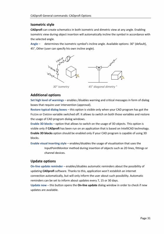
Isometric style
CADprofi can create schematics in both isometric and dimetric view at any angle. Enabling
isometric view during object insertion will automatically incline the symbol in accordance with
the selected angle.
Angle – determines the isometric symbol’s incline angle. Available options: 30° (default),
45°, Other (user can specify his own incline angle).
30° isometry 45° diagonal dimetry °
Additional options
Set high level of warnings – enables /disables warning and critical messages in form of dialog
boxes that require user intervention (approval).
Restore typical dialog boxes – this option is visible only when your CAD program has got the
FILEDIA or CMDDIA variable switched off. It allows to switch on both those variables and restore
the usage of CAD program dialog windows.
Enable 3D blocks – option that allows to switch on the usage of 3D objects. This option is
visible only if CADprofi has been run on an application that is based on IntelliCAD technology.
Enable 3D blocks option should be enabled only if your CAD program is capable of using 3D
blocks.
Enable visual inserting style – enables/disables the usage of visualization that uses the
InputPointMonitor method during insertion of objects such as 2D lines, fittings or
channel devices.
Update options
On-line update reminder – enables/disables automatic reminders about the possibility of
updating CADprofi software. Thanks to this, application won’t establish an internet
connection automatically, but will only inform the user about such possibility. Automatic
reminders can be set to inform about updates every 7, 15 or 30 days.
Update now – this button opens the On-line update dialog window in order to check if new
updates are available.
CADprofi General commands: CADprofi layers
Page 32
CADprofi layers In CADprofi program it is possible to enable the mechanism of automatic layer management.
This feature is very convenient, since it relieves user from the necessity of placing objects on
appropriate layers. When the automatic layer management option is enabled it is easier to
mantain the adequate organization of created drawings, and as a result it is possible to obtain
detailed BOMs sorted by industry or type of objects. Appropriate layer structure will also
make the printing creation easier.
In order to maintain appropriate line colours and thickness user should use the CADprofi
Color.ctb or CADprofi Mono.ctb plot/printing styles. If CADprofi plot styles are not avilable in
the CAD program then user should copy all files from the C:\Cadprofi\xx\PlotStyle to the
appropriate CAD folder (location of this folder can be checked in the CAD program options
e.g. for BricsCAD V13 En installed on the Windows 7 it is the following folder:
C:\Users\Xxx\AppData\Roaming\Bricsys\Bricscad\V13\en_US\PlotStyles
CADprofi layer structure
Names used for layers that are automatically created by CADprofi consist of several parts:
First 3 characters define the design branch and the type of the created drawing (2D, 3D
etc.).
Next characters define the type of object e.g. a symbol, line, duct etc.
The ending of the layer name is used to define the belonging of object to a specific
installation, type of material, line type, wall etc. (e.g. S-Supply, R-Return, I-Supply air).
The ending is created by using the extended layer structure (check page 29).
It is also possible to create additional layers in CADprofi program such as these that show the
drawing details (details, axes, hidings) as well as special layers.
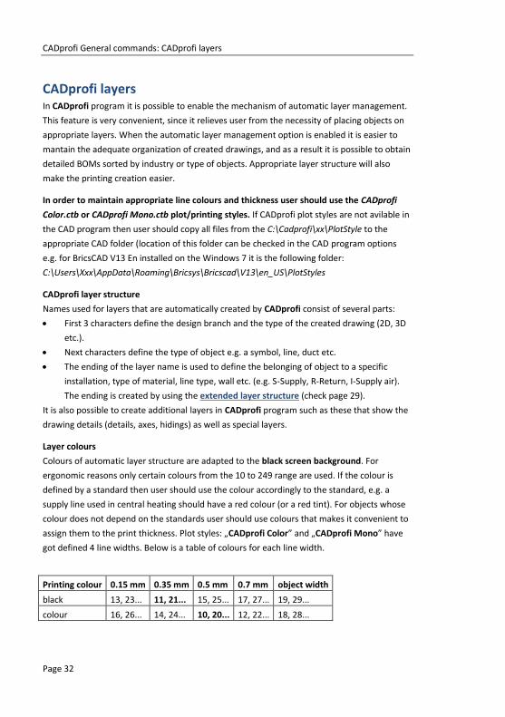
Layer colours
Colours of automatic layer structure are adapted to the black screen background. For
ergonomic reasons only certain colours from the 10 to 249 range are used. If the colour is
defined by a standard then user should use the colour accordingly to the standard, e.g. a
supply line used in central heating should have a red colour (or a red tint). For objects whose
colour does not depend on the standards user should use colours that makes it convenient to
assign them to the print thickness. Plot styles: „CADprofi Color” and „CADprofi Mono” have
got defined 4 line widths. Below is a table of colours for each line width.
Printing colour 0.15 mm 0.35 mm 0.5 mm 0.7 mm object width
black 13, 23... 11, 21... 15, 25... 17, 27... 19, 29...
colour 16, 26... 14, 24... 10, 20... 12, 22... 18, 28...

CADprofi General commands: Attributes and descriptions
Page 33
18, 28 ... 19, 29 ... colours don't have a defined print width (they have got the object width
set) and are not used in CADprofi program. User can use these colours without fear of conflict
with the program's layer structure (colours).
Thaw layer groups
In CADprofi program there are commands used to easily
enable or disable group of layers, such as all architectural
layers or detail layers.
Commands from the Thaw layer groups are used to quickly
enable a group of layers from a given module or layers that
define the drawing detail level (axes, hidings etc.).
Thaw layer group toolbar
Show all layers – turns on the visibility of all CADprofi layers in the
drawing.
Show 2D layers only – turns on the visibility of layers that contain 2D objects,
layers that contain 3D objects will be frozen.
Show 3D layers only – turns on the visibility of layers that contain 3D objects,
layers that contain 2D objects will be frozen.
Freeze layer groups
In CADprofi program there are commands used to easily
enable or disable group of layers, such as all mechanical
layers or hidings.
Commands from the Freeze layer groups are used to
quickly disable a group of layers from a given module or
layers that define the drawing detail level (axes, hidings
etc.).
Freeze layer group toolbar
Freeze 2D layers – freezes all layers that contain 2D objects.
Freeze 3D layers – freezes all layers that contain 3D objects.

CADprofi General commands: Attributes and descriptions
Page 34
Attributes and descriptions During the symbols and objects insertion, CADprofi program is adding various descriptions
and technical parameters to them. This data is stored as attributes. The Attributes and
descriptions command allows to edit the attributes, as well as to add descriptions (as a simple
text) into the drawing. All data that is used in the attributes can be later used during the BOM
creation.
After user chooses the command he should indicate an object, whose parameters he would
like to edit. This command gives the possibility to edit many objects thank to the Multiple
function ("M" key). As an effect it will be possible to edit parameters of all indicated blocks.
After indicating the objects a new dialog window that contains all attributes will appear.
If user has selected several object it's possible that a ***Varies*** value may appear in some
data. It means that objects have got different values of a specific parameter. Editing this
parameter will also edit it in all of the selected blocks. If this parameter won't be edited then
the value won't change in any of the selected blocks.
Attributes and descriptions
Attributes and descriptions dialog window
CADprofi General commands: Attributes and descriptions
Page 35
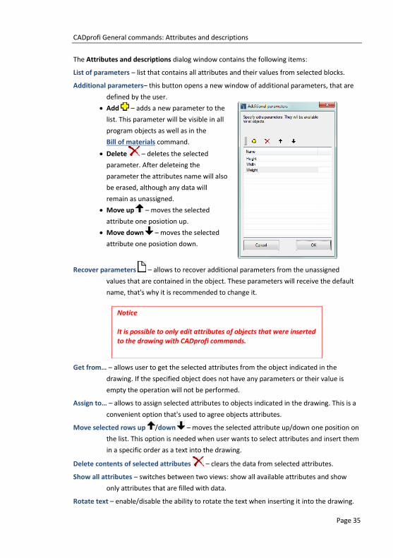
The Attributes and descriptions dialog window contains the following items:
List of parameters – list that contains all attributes and their values from selected blocks.
Additional parameters– this button opens a new window of additional parameters, that are
defined by the user.
Add – adds a new parameter to the
list. This parameter will be visible in all
program objects as well as in the
Bill of materials command.
Delete – deletes the selected
parameter. After deleteing the
parameter the attributes name will also
be erased, although any data will
remain as unassigned.
Move up – moves the selected
attribute one posiotion up.
Move down – moves the selected
attribute one posiotion down.
Recover parameters – allows to recover additional parameters from the unassigned
values that are contained in the object. These parameters will receive the default
name, that's why it is recommended to change it.
Get from… – allows user to get the selected attributes from the object indicated in the
drawing. If the specified object does not have any parameters or their value is
empty the operation will not be performed.
Assign to… – allows to assign selected attributes to objects indicated in the drawing. This is a
convenient option that's used to agree objects attributes.
Move selected rows up /down – moves the selected attribute up/down one position on
the list. This option is needed when user wants to select attributes and insert them
in a specific order as a text into the drawing.
Delete contents of selected attributes – clears the data from selected attributes.
Show all attributes – switches between two views: show all available attributes and show
only attributes that are filled with data.
Rotate text – enable/disable the ability to rotate the text when inserting it into the drawing.
Notice
It is possible to only edit attributes of objects that were inserted to the drawing with CADprofi commands.

CADprofi General commands: Attributes and descriptions
Page 36
Draw frame – enable/disable the frame for the text, that will be inserted into the drawing.
Leader – allows to draw a line between the object and the inserted text.
Text size – options that specify the size of inserted text.
Height – specifies the block text height in millimeters.
Scale – allows to specify the scale in which the drawing will be printed.
Text style: normal or isometric – allows to specify the text style in both normal and
isometrical views.
Description – opens window with an optional object description. This function is used only in
certain objects from the manufacturers databases.
Save attributes – closes the dialog window and saves all the changes in selected blocks.
Insert text – saves all the changes made in the selected blocks, and allows to insert to the
drawing the value of selected attributes as a plain text. In order to insert the text,
user should indicate a point that specifies the first line of text. Depending on the
rotation option, it may be necessary to indicate a second point that specifies the
text rotation angle. Instead of indicating a second point it's possible to indicate the
angle size (e.g. "0" or "90"). In this case, the text will be inserted horizontally.
The style of the inserted text depends on the current CAD program style.
Description in axonometric drawings
The Insert text command allows to insert texts in axometric drawings. In order to insert text
in isometry or dimetry user should select the Text style – isometric option.
When inserting text in isometry CADprofi will activate
the isometric mode for the graphic cursor, thanks to
which it will be easier to determine the position and text
insertion angle along the desired axis. Isometric cursor is
automatically set only when the isometric angle is set to
30°. When inserting text in dimetry it is convenient to
enter the text angle in the command line. The angle
should be set in accordance with the axonometrical
angle that is set in CADprofi Options (page 28) dialog
window.

CADprofi General commands: Frames and tables
Page 37
Frames and tables An important part of each drawing is a frame and table.
The Frames and tables command offers users a convenient way to insert standard frames and
tables to the drawing:
Tables – standard drawing tables.
Specifications – tables used to create drawing specifications.
Legends – standard legends that contain recommended line layers for installations.
User tables – empty tables, which can be defined by the user.
Frames and tables dialog window
The dialog window contains the following items:
Angle/Rotate – gives the possibility to specify a fixed table insertion angle or to enable the
rotation option, at which the angle is determined by the rotation.
Symbols size – a value that specifies the frame or table scale.
Hint
Legends and drawing specifications can be created using the "Bill of materials ".

CADprofi General commands: Frames and tables
Page 38
Frames
Frame view can be changed by turning on or off the following options: Reference grid,
Centering marks, Crop marks and Untrimmed size.
Tables
All tables that are available in the program have got a possibility to edit the information about
the project. Some tables are interactive, and for them it is possible to specify all data in the
dialog window.
For interactive tables, edition or selection fields (with a pull-down list of typical values under
the button) are available. If in one project (drawing) user inserts many sheets, then the
program can enumerate them with the and button. The Data field is filled up
automatically.
In order to edit tables after inserting them into the drawing, it's possible to use the CADprofi
Attributes and descriptions command or an appropriate CAD program command e.g. DDATTE
(_DDATTE).

CADprofi General commands: Frames and tables
Page 39
Procedures Inserting a frame and a table
1. Run the Frames and tables command.
2. Select the frame, e.g. A2 – ISO.
3. Select the elements that should be included in the frame
(Reference grid, Centering marks etc.).
4. Click the Insert button to insert the frame into the drawing.
5. Once again run the Frames and tables command.
6. Select a table, e.g. Table – ISO 1.
7. Fill up the data about the project.
8. Click the OK button in order to insert the table into the drawing. As the insertion
point user should indicate the right, down corner of the previously inserted table.
9. (Optional) Select the Edit symbols command to change the text in the tables or to
change table into a different one.
10. (Optional) Change attributes in the table with the help of the CAD program. These
changes can be done with the _ATTEDIT command or in the object properties
window.
User tables
User can create and add to the program his own tables or frames that are used in the
drawing.
Tables that are included in CADprofi program allow user to edit data (blocks attributes). In
order for the user tables to have the same functionality, it is necessary to include the
appropriate attributes definitions for the created tables.
A convenient way to do this, is to insert and explode a standard table, edit it and afterwards
add it as a user block.
The way how to define user own elements is described in detail in the Defining user blocks
chapter (check page 89).

CADprofi General commands: Numbering
Page 40
Numbering The numbering system allows to assign numbers to symbols and objects that were created
with CADprofi program. Objects data as well as their numbers is used to create descriptions
and specifications. The Numbering command can work in two modes. If user runs the
command and selects an object or symbol, that hasn't been previously numbered, then the
program will allow to number objects. On the other hand if user indicates an object that
already has a number, then the command will work in a delete numbers mode.
Program uses separate numbers strings used for various installations, industries and objects
types. This means that when user numbers objects, for example from the electrical module,
then the program will start the numbering from the number 1. If user starts the numbering
process with a different module, then the program will start again from the number 1. To
distinguish different numbering strings it is recommended to add prefixes or suffixes to them,
so they will look different (e.g. E-1, E-2 for the exhaust system and S-1, S-2 for the air supply).
CADprofi uses the following strings:
Numbering of 2D lines and fittings for both piping and ventilation installations - separate
numbering for the following installations: supply, return, sewage, exhaust, supply air.
Numbering of 2D electrical trays - separate numbering for different systems.
Numbering of symbols, objects - common numbering is used for all elements from a
particular module.
Notice
The Numbering command is used to add order numbers to individual elements of the project.
CADprofi program also have another methods of numbering: 1. Numbering of electrical apparatus labels. 2. Numbering used for process automation.
3. Numbering (addressing) for electrical circuits. 4. Numbering used for sheets (tables). 5. Numbering used with symbol's marks, which in some cases
can be used alternatively to the "Numbering" command.

CADprofi General commands: Numbering
Page 41
Assigning numbers
In the dialog window user should specify the numbering mode as well as size and appearance
of numbers that will be inserted. The number can consist of three parts:
Correct number must have an integer value from 0 to 32767.
Prefix - any kind of text. Prefix is often used as an indication of an installation or system,
e.g. number "A4-12.1" has got a "A4" prefix which means it's a fourth air supply system.
The Prefix from system name option is used for automatic addition of prefixes.
Suffix – any kind of text. In case of using a multi-level numbering it is possible to
automatically add suffixes to them. In order to enable this method user should turn on
both Fix number and Number suffix options. After that CADprofi will start numbering
only the last of the number.
Examples of a multi-level numbering (only the last part is being numbered):
A4–7–1 A4–7–2 A4–7–3
A4–7–1.2.1 A4–7–1.2.2 A4–7–1.2.3
7–1.2.1 7–1.2.2 7–1.2.3
Numbering dialog window
The dialog window contains the following items:
Prefix – box that allows to add a numbering prefix.
Number – box that allows to specify the object number.
Suffix – box that allows to add a numbering suffix.
Use automatically free numbers – automatically assign numbers to indicated objects.
Disabling this option will allow user to manually set the value.

CADprofi General commands: Numbering
Page 42
Prefix from system name – automatic completion of prefixes.
Allow number repeating – gives the possibility to repeat object numbers.
Fix number – enables usage of a fixed number for all numbered objects. Enabling this option
allows to use suffix numbering.
Number suffix – numbering by adding numbers to the suffix.
Automatic position – automatic placement of a numbering block in a point indicated during
the object selection. Enabling this option gives the possibility to specify the
placement of the numbering block for each indicated object.
Draw leader – draws a leader between the indicated object and the numbering block.
Numbers size – option that gives the possibility to specify the numbers size on the printing:
Height – specifies the block text height in millimeters.
Scale – allows to specify the scale in which the drawing will be printed.
Numbering
After user runs the Numbering command he should indicate an object. If this object doesn't
have a number, then a dialog window will appear, in which it will be possible to specify the
numbering options. In order to start the numbering process press the OK button and
depending on settings indicate the numbering placement for the previously indicated object.
The command will remain in the numbering mode, allowing user to number additional
objects. Within a single numbering command, only objects from the same branch/industry
can be numbered. It means that if user starts numbering for example an air supply installation
then till he ends the command he will able only to number lines, fittings and objects from the
air supply installations. If user wants to number other installations he has to run the
command again. In the case of indicating an object, that does not belong to the same
branch/industry or if a selected object already has a number then this object won't be
numbered e.g.> Object is not compatible with previously selected object or > This object has
already got a number: 1.
Procedures Numbering
1. Run the Numbering command.
2. Indicate the first object that you would like to number, this object will serve as a
source object for a given numbering string. The Numbering dialog window will
appear.
3. (Optional) Specify the numbering options.
4. (Optional) Specify the numbers size on the printing by setting both Height
and Scale for numbering block texts.
5. Click the OK button to close the window and start the numbering process.

CADprofi General commands: Numbering
Page 43
6. (Optional) If the Automatic position option has been turned off then specify the
position for the first object number.
7. (Optional) Indicate additional object that you would like to number. If it’s
necessary you can also indicate numbering blocks.
8. You can end the command by clicking the Esc or Enter keys.
Numbering
Example of different numbering strings in a single drawing
Deleting numbers
During the numbering process to the objects, the numbers are assigned both as a visible text
and as an invisible data. Deleting text with the number won't delete number from the object.
For this reason, in order to delete numbers, user should use the Numbering command.
If user selects after he runs the command, a block that contain information about numbering
then a window will appear, that allows to enable the remove numbers mode.
After user activates the remove numbers mode, he should to select desired objects or
numbers. Internal information as well as number texts and leaders will be removed.

CADprofi General commands: Numbering
Page 44
Procedures Deleting numbers
1. Run the Numbering command.
2. Select an object that contains numbers (P1). A dialog window will open.
3. Choose Yes, to start the process of removing numbers.
4. The number of the first selected object will be deleted.
5. (Optional) Indicate additional objects (P2–P3), from which you would like to
remove numbers.
6. End the remove numbers command by clicking the Esc or Enter key.
Notice
Numbering is being removed from objects when user: 1. Inserts equipment in 2D lines or ducts.
2. Connects some certain lines or ducts. 3. Runs the “2D Divide pipes/ducts command”. 4. Removes the symbols by using the "Delete symbols"
command.
Copying objects with numbers
After copying, user should remove invalid numbers and renumber the copied objects again. In
order to delete these numbers user can use the remove numbers mode from the Numbering
command. After user runs the command he should indicate the invalid text (P1), and then
with the help of the selection window delete texts (P3–P4). Other objects may be present in
the selection window, as the command will only remove numbers.

CADprofi General commands: Numbering
Page 45
Notice
Very important: When user copies numbered objects the
source elements are treated as objects
without numbers!!!
Removing invalid numbers and renumbering of copied objects
Copied objects with
invalid numbers Source objects
Removing invalid numbers
Renumbering copied
objects

CADprofi General commands: Bill of materials
Page 46
Bill of materials The Bill of materials command allows to obtain various data extracts and printings. The
easiest and fastest way to receive a specification is to select one of templates and to directly
print it. There are several pre-designed templates to choose from, and they are used to obtain
various specifications. Depending on the selected template, CADprofi performs filtering of
selected objects. For instance, when user selects specifications for symbols, CADprofi will
select only symbols.
Each template provides different data that can be printed in tabular layouts. All needed data
are available on the left side of the dialog window. Columns that will be printed are located
on the right side of the dialog window. It is possible to select data to the list of printed
columns as well as to change the column sequence. BOM can be printed in both horizontal
(landscape) and vertical (portrait) mode. For horizontal (landscape) mode, user can select
more columns.
Bill of materials (BOM) dialog window
The dialog window contains the following items:
Select type of BOM– a list that contains pre-design templates. User can adapt the Objects,
symbols and lines CADprofi template to his own needs. Definition of this template
is located in the C:\Cadprofi\X.x\Common\Extract\Extrac.utc file. In this file it is
possible to names of attributes and additional data that is used in BOMs. Futher
information can be found in comments in the mentioned file.

CADprofi General commands: Bill of materials
Page 47
Available columns – list of attributes, which values can be used in the printed table. The list is
dependant on the chosen type of BOM.
Printed columns – list of attributes that will be included in the columns of the printed table.
This list can be later edited by the user.
Add – adds the selected attribute to the list of printed columns.
Delete – removes the selected attribute from the list of printed columns.
Up, Down – allows user to specify the positions order on the list of printed columns.
The Printed columns list can also organize by drag and drop function.
Summing data – enable/disable the creation of a collective bill of materials with summing
data of used identical objects. It is also possible to include the line length, ducts
area, fittings data etc. in the summing data.
Sort – enable/disable data sorting on printings. Data can be sorted in the next dialog
window that contains the initial printing preview.
Skip special symbols – enable/disable the inclusion of blocks that haven't got the NAME
attribute or the ones for which the NAME attribute doesn’t have any value. Also in
BOMs, blocks that are used to describe the drawing (slope symbols, number of
core electric wires etc.), are not included.
Landscape print – enable/disable the creation of horizontal (landscape) printings.
Header of a company – enable/disable the printing of the header of a company on the first
page of BOM. The data needed for the header and the company logo are being
defined in the next dialog window that contains the initial printing preview.
Ordinal number on print – enable/disable the addition of the column with the order number.
Next – confirms the selected options and proceeds to the selection of objects on the
viewport. To select them, user can use all kind of methods in the CAD program.
The application itself will filter objects according to the chosen template. Thanks to
this instead of selecting single objects, it’s possible to indicate an area with two
points.
Hint
On the left side of the dialog window there are additional parameters that can be defined by user. Thanks to this, it is possible to use these parameters in BOM -
„Additional parameters” (check page 35).
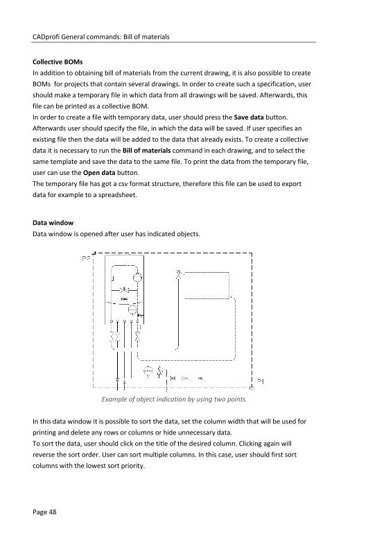
CADprofi General commands: Bill of materials
Page 48
Collective BOMs
In addition to obtaining bill of materials from the current drawing, it is also possible to create
BOMs for projects that contain several drawings. In order to create such a specification, user
should make a temporary file in which data from all drawings will be saved. Afterwards, this
file can be printed as a collective BOM.
In order to create a file with temporary data, user should press the Save data button.
Afterwards user should specify the file, in which the data will be saved. If user specifies an
existing file then the data will be added to the data that already exists. To create a collective
data it is necessary to run the Bill of materials command in each drawing, and to select the
same template and save the data to the same file. To print the data from the temporary file,
user can use the Open data button.
The temporary file has got a csv format structure, therefore this file can be used to export
data for example to a spreadsheet.
Data window
Data window is opened after user has indicated objects.
Example of object indication by using two points
In this data window it is possible to sort the data, set the column width that will be used for
printing and delete any rows or columns or hide unnecessary data.
To sort the data, user should click on the title of the desired column. Clicking again will
reverse the sort order. User can sort multiple columns. In this case, user should first sort
columns with the lowest sort priority.

CADprofi General commands: Bill of materials
Page 49
To specify the column width, user should set the cursor between the columns (in the header).
Cursor will change into a double-headed arrow that will allow to change the width by
dragging. In this way it is possible to completely hide selected columns. This option is useful
to hide empty columns or columns that are not needed for printings.
In the preview window user should specify the printing title. It is also possible to define the
printing header such as: contact details and company logo.
Data printing from current drawing dialog window
Print – allows to print or export the data into many formats.
Csv export – allows to instantly export the data into a csv file, which can be loaded into
applications such as MS Excel, Open Office or others.
Draw – is used to create graphical legends and for automatic filling of specification tables.
User data – allows to specify the contact details and the company logo.
Remove – allows to delete rows that contain data. It is also possible to delete data by
pressing the Delete button.

CADprofi General commands: Bill of materials
Page 50
Printing/Data export
After clicking the Print button a window will appear with printing options.
Printing options dialog window
It is possible to directly print the document on a chosen printer or to export the data to
various formats (xls, txt, rtf, pdf, html, xml and many more).
A useful option is a possibility to print the first page of specification on another printer than
other pages. This option can be used to print the first page that contain the company logo on
a color printer and other pages on a monochrome printer.
Printing preview dialog window
When user exports data it is possible to specify the export parameters such as only export the
data, or export data with used formatting style.

CADprofi General commands: Bill of materials
Page 51
Procedures Printing specification
1. Run the Bill of materials command.
2. Choose a template from the list of available templates in order to determine the
BOM type.
3. (Optional) Add or delete a position in the Printed columns panel.
4. (Optional) Choose the printing option for specification.
5. Click the Next button.
6. Select objects from the drawing that you would like to include in the specification.
Confirm by pressing the right mouse button or the Enter key.
7. (Optional) Change settings in the Data window.
8. Click the Print button.
9. In the newly opened Printing options window in the Export medium card select
the printer type that you would like to use.
10. (Optional) Change settings in the Printing options.
11. Click the Start button to begin printing.
Data export (Excel)
1. Run the Bill of materials command.
2. Choose a template from the list of available templates in order to determine the
BOM type.
3. (Optional) Add or delete a position in the Printed columns panel.
4. (Optional) Choose the printing option for specification.
5. Click the Next button.
6. Select objects from the drawing that you would like to include in the specification.
Confirm by pressing the right mouse button or the Enter key.
7. (Optional) Change settings in the Data window.
8. Click the Print button.
9. In the newly opened Printing options window in the Export medium card expand
the list Directly to… and select Microsoft Excel Format.
Hint
Printing preview can be saved in files with an LL extension. To view these files, user can use the "LLview11.exe" program, which is located on the disk, in the CADprofi main folder (e.g.
"C:\CadProfi\X.x").
Direct printing is not available in some 64bit CAD programs.

CADprofi General commands: Bill of materials
Page 52
10. (Optional) Click the Options button and go the Result card. It disables the Export
data only from objects table option to save formatting.
11. (Optional) Change settings in the Printing options.
12. Click the Start button to begin the data export.
Creating specifications (Mechanical)
Creating specifications
Exporting to Excel with preserved formatting style
Creating legends and specifications
In order to create a specification or a legend with the help of the specification wizard user
should press the Draw button. Two modes are available: Legend and Specification.
The Legend mode is used to create any defined legends or specification tables. In this mode it
is possible to determine the overall table width, the spacing between columns and rows and
the text style. The legend may contain a header with a specification title and the titles of each
column.
The Description column is particularly important. After enabling the option: All data in the
'Description' column, the legend will be created in which all data that will be acquired from
the drawing will be consolidated into one description column.
When disabling the above option, it is possible to create tables that contain many columns.
Legends that contain symbols and objects views are created only if the Block column has
been selected in the specification wizard. In this case symbols that are in the legend can be
Hint
It is also possible to export the data to the Excel program with the „Export csv” button.

CADprofi General commands: Bill of materials
Page 53
placed on layers accordingly to symbols layers in the drawing. Thanks to this, symbols that are
in the legend have got saved colours and characteristics of the original objects from the
drawing.
Legends columns width is determined in proportion to the column width that is set in the
main data window. After setting the mouse cursor between the columns, the cursor changes
into a double-headed arrow that allows to change the width.
Legend, specification dialog window
Notice
Legends that contain symbols are created only on the basis of the current drawing (it is not possible to create a collective graphical legend from several drawings).

CADprofi General commands: Bill of materials
Page 54
Procedures Creating a legend
1. Run the Bill of materials command.
2. Choose one of available templates, in order to specify the BOM type.
3. (Optional) Add or delete positions in the Printed columns chart.
4. (Optional) Choose the printing option for specification.
5. Click the Next button.
6. Select objects from the drawing that you would like to include in the specification.
Confirm by pressing the right mouse button or the Enter key.
7. (Optional) Specify the settings in the data window.
8. Click the Draw button.
9. In the newly opened Legends, specifications window choose the Legend option.
10. (Optional) Specify the specification table settings.
11. (Optional) Specify the text size and style.
12. Click the OK button.
13. (Optional) Select Yes/No in the newly opened dialog window in order to
delete/save the existing legend.
14. Specify the legend insertion point.
Creating graphical legends
The Specification mode is used to fill template specification drawing tables. These
specifications are prepared on the basis of appropriate standards. Because of that the
specifications tables have got a precisely defined structure (column width, appropriate text
size and style etc.). When inserting a specification table into the drawing, user should make
sure that he has chosen the right columns with data in the specification wizard, that belong to
the appropriate table type. Otherwise, the tables won't be properly filled. The All data in the
‘Name’ or ‘Description’ box allows to consolidate the data in the column that contains a
name.
Notice
There is a set of names of each parameter in the program such as: "Name", "Type", "DN", "PN" etc. In certain tables it is necessary to use other names, e.g. the parameter "Type" in
some tables is the equivalent to the "Symbol" or 'Marking" parameter.

CADprofi General commands: Bill of materials
Page 55
Legend, specification dialog window
Procedures Creating a specification
1. Run the Bill of materials command.
2. Choose one of available templates, in order to specify the BOM type.
3. (Optional) Add or delete positions in the Printed columns chart.
4. (Optional) Choose the printing option for specification.
5. Click the Next button.
6. Select objects from the drawing that you would like to include in the specification.
Confirm by pressing the right mouse button or the Enter key.
7. (Optional) Specify the settings in the data window.
8. Click the Draw button.
9. In the newly opened Legends, specifications window choose the Specification
option.
10. (Optional) In the Settings chart select the Specification type.
11. (Optional) Enable/disable the All data in the ‘Name’ or ‘Description’ box option.
12. (Optional) Change the text size and style.
13. Click the OK button.
14. (Optional) Select Yes/No in the newly opened dialog window in order to
delete/save the existing specification.
15. Specify the specification insertion point.

CADprofi General commands: Bill of materials
Page 56
An example table contains columns with No., Symbol (type), Description, and Sum. In this
case in the specification wizard user should choose the Type and Name columns. Sum column
is being filled only if the Summing data option is enabled. No. column is filled only if the
Ordinal number on print option is enabled.
Notice
Blocks that are included in the tables are used only for the purpose of symbol/object illustration. They don't possess the
data needed for proper use in CADprofi project. For this reason
it is not recommended to copy blocks from the drawing.
Creating line and cable specifications
In order to successfully create a specification that contains schematic lines user should select
the appropriate template that filters objects (Plumbing/heating/air condition/electrical -
lines). In this type of specifications, CADprofi program includes cables drawn as lines or
polylines, as well as sections of vertical lines drawn as risers’ symbols.
Procedures Creating a line specification
1. Run the Bill of materials command.
2. Select the template that is used for schematic lines for the appropriate branch.
3. (Optional) Add or delete positions in the Printed columns chart.
4. (Optional) Enable the Summing data option in order to have the visible Sum
column in the specification.
5. Click the Next button.
6. Select objects from the drawing that you would like to include in the specification.
Confirm by pressing the right mouse button or the Enter key.
7. Print or insert into the drawing the created specification.

CADprofi General commands: Bill of materials
Page 57
Creating specifications of lines, ducts and 2D cable trays
Fittings and air condition ducts with a rectangular cross-section that are prepared from steel
are usually connected with the use of flanges. In CADprofi such elements are simplified
(without flanges) therefore user should specify in the project the type or the technology
used in the air condition lines. An appropriate annotation should be included in the
descriptive section. If necessary, it is possible to insert flanges into the drawing with the use
of appropriate CADprofi command. Designer can also decide whether the flanges inserted in
the drawing should be included in the specification.
The simplified drawings allow to use most lines and fittings from the CADprofi program in any
installation projects that use different technologies, materials and connection methods (e.g.
metal and artificial/plastic lines installations etc.).
During the specification creation it is possible to add the area of lines and fittings. The area is
being calculated on the basis of the PN-EN 14239 standard.
In specifications it is possible to add dimensions or types (markings) of fittings or lines. Fitting
type is available only in the case of using elements that are chosen from manufacturers’
databases. In another case type is not specified and in the specifications only the main
dimensions are included. These dimensions are appropriate with markings that are included
in the catalog of 2D fitting drawings. We propose to print and add the catalog of 2D fittings to
the specification. The catalog of 2D fittings can be found in the Fittings.pdf folder that is
located in the file_gb folder, which can be found in the CADprofi installation folder.
Cable trays, cable ladders, protective tubes and other elements are available in the Electrical
module. Some fittings that are in the 2D fittings catalog are not used in electrical installations
and therefore they are not available in the Electrical module.
Flexible cables with a circular cross-section (FLEX) or flexible protective tubes from the
Electrical module are drawn with the help of straight sections and fittings. Still fittings are
being treated as lines/cables therefore in specifications all flexible elements are being shown
as flexible lines with specified length.
In order to include length and the amount of each line/duct/cable tray sections in the
specification user should add both Length and Ducts pcs (number of pieces) columns.
In order to add only the total length of line/duct/cable tray with the same cross-section in the
specification, user shouldn't include the No., Length and Ducts pcs columns.
Hint
Add the „Fittings.pdf” printing to the fittings specification.

CADprofi General commands: Bill of materials
Page 58
An example of a specification of air conditioning installation elements:
This column includes the number of
lines/ducts sections with the same length.
E.g. 6 sections with an 1800 mm length.
In the Length column the
element length is specified
in mm.
E.g. sections with a 1800 mm
length
The Area column contains the
element area in m2 or the total area
of all elements that were included in
the specification.
The Sum column contains the total length of lines /
trays / ducts in meters. The Sum column is shown
only if user has enabled the Summing data option
during the specification creation.
Fittings
Fittings types or dimensions
are shown in the Article
column. All dimensions are
the same as those that are
used in the drawings from
the catalog of 2D fittings.
In the air condition
installations it is possible to
add the Area column that
contains area (in m2) of
elements that are counted
accordingly to the PN–EN
14239 standard.
For fittings the
Sum column
contains the total
amount of fittings
from each type.
In the above example there are two 90º elbows in the specification with
an ø300 diameter and R=450 (1,5D) radius.

CADprofi General commands: CADprofi – Tools
Page 59
CADprofi – Tools
Editing commands are located in the upper program menu, as well as on a separate
CADprofi – Tools toolbar. These commands are universal and they work with objects from all
CADprofi modules. To ensure a fast access to these commands it is recommended to enable
the editing toolbar.
CADprofi – Tools toolbar
Delete symbols
The Delete symbols command is used to delete symbols and armature. When deleting
elements that were inserted in lines, program will automatically connect these lines.
When deleting numbered symbols, numbers will also be deleted. It is possible to indicate
many drawing elements; still the program will delete only these symbols and objects that
were inserted with the use of CADprofi commands.
Procedures Deleting symbols
1. Run the Delete symbols command.
2. Indicate a symbol that will be deleted from the drawing or line (P1).
3. (Optional) Select the Multiple option to indicate many objects (P4–P5).
Confirm by clicking the Enter button.
4. Indicate additional elements (P2, P3) or finish the command by clicking the Enter
or Esc key.

CADprofi General commands: CADprofi – Tools
Page 60
Procedures Deleting armature
1. Run the Delete symbols command.
2. Click the first element (P1). It will be deleted, and in its place the line will
be lengthened.
3. (Optional) Click additional elements (P2, P3).
4. End the command with the right mouse button or the Enter key.
P1 P2
P3

CADprofi General commands: CADprofi – Tools
Page 61
Quick edition
The Quick edit command allows to perform basic editing operations on symbols and objects.
After running the command, user should indicate the symbol that he would like to edit. Near
the symbol, additional markers will appear that allow to instantly make the necessary
changes.
Markers that are displayed after indicating the object:
Mirror – markers that allow to perform symbol mirroring.
Scale – allow to increase or decrease the symbols size on the drawing. The sign
increases the symbol’s scale by 25%. The sign reduces the symbol’s scale
by 25%. If the current scale value is 200, then the markers will increase/decrease
the symbol’s scale by 50.
Copy – allow to quickly create multiple copies of the indicated object.
Rotation – allow to rotate the symbol around the insertion point. If the symbol is located
in the line then the application will only allow to rotate it by 180°.
Lengthen – this marker is used to lengthen or shorten normalized elements e.g. screws,
rivets, etc. (check page 305).
Switch – allows user to change the side of windows and doors isnertion by turning the
selected element without losing its position.
Quick edit is often used after user adds several symbols into the drawing e.g. with the
Multisymbols command. If several symbols are being inserted then it is possible that some
symbols may be inserted in the opposite way. Quick edit will allow to quickly rotate them in
the proper way.
The Quick edit command is also useful to turn objects, e.g. when it’s needed to change the
direction of duct devices or armature.
Procedures Quick edition
1. Run the Quick edit command.
2. Indicate a symbol that will be edited.
3. (Optional) Rotate the symbol with the Mirror command (P1, P2).
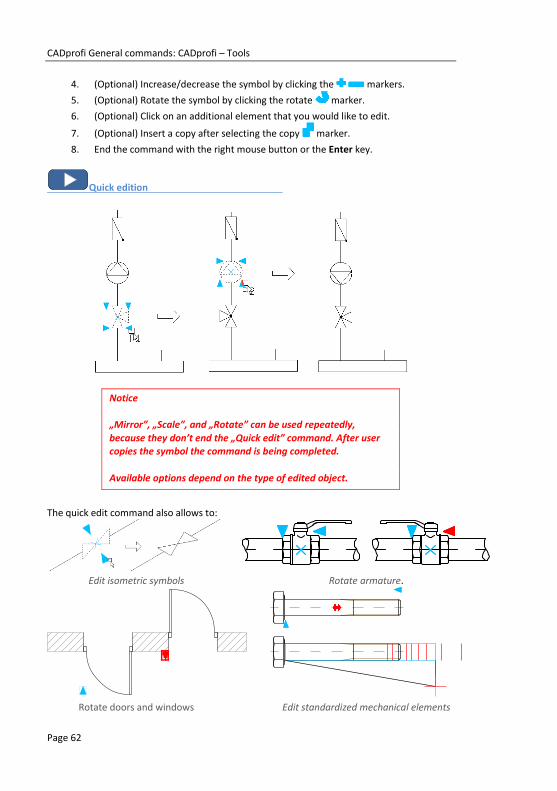
CADprofi General commands: CADprofi – Tools
Page 62
4. (Optional) Increase/decrease the symbol by clicking the markers.
5. (Optional) Rotate the symbol by clicking the rotate marker.
6. (Optional) Click on an additional element that you would like to edit.
7. (Optional) Insert a copy after selecting the copy marker.
8. End the command with the right mouse button or the Enter key.
Quick edition
Notice
„Mirror”, „Scale”, and „Rotate” can be used repeatedly,
because they don’t end the „Quick edit” command. After user copies the symbol the command is being completed.
Available options depend on the type of edited object.
The quick edit command also allows to:
Edit isometric symbols Rotate armature.
Rotate doors and windows Edit standardized mechanical elements

CADprofi General commands: CADprofi – Tools
Page 63
Symbols edition
The Edit symbols command allows to freely edit CADprofi symbols or objects. This
command is particularly important when editing multivariant symbols such as: welding marks,
roughness marks, armature, apparatus and many more.
To change the symbols, select the Edit symbols command and choose the desired symbol. A
dialog window will appear which was used to insert the indicated symbol. Make all the
necessary changes in the dialog window. After clicking the Insert, Apply or OK button the
symbol will be updated on the drawing accordingly to the changes that we made.
The Edit symbols command also allows to convert a symbol in an alternative one.
Symbols edition
Symbols conversion
Symbols edition
Insert similar object
During projects creation it's often needed to insert symbols or objects from many libraries
and categories. Because CADprofi program has got a very big content, choosing the right
element may require excessive searching of libraries or changing categories. In order to speed
up work, user may use the Insert similar object command.
After selecting the Insert similar object command user should indicate an element on
the drawing. Program will open this element in its original dialog window.
This command makes it easier to insert alternately both one pole and multi pole symbols
when creating electrical schemes. In the HVAC & Piping module the Insert similar object
command can be often used to alternately armature symbols and devices from different
categories into the drawing.
The Insert similar object command can be used for all CADprofi program elements, including
HVAC, air condition, furniture, construction and other elements.

CADprofi General commands: CADprofi – Tools
Page 64
Create alternative view
In CADprofi there are many objects that have got the possibility to select the insertion view.
Depending on the selected object certain 2D views will be available and for some
manufacturers' libraries also 3D views. The Create alternative view command allows to
quickly place one of available alternative views. When using this command, a new block is
being inserted into the drawing.
Create alternative view dialog window
The dialog window contains the following items:
Select type of action – list of available views or procedures for selected block.
Additional settings – settings for some elements that contain texts.
Repeat the command – enable/disable the possibility of re-inserting the element for selected
repeatedly inserted objects (omitting the dialog window).

CADprofi General commands: CADprofi – Tools
Page 65
Creating schemes with the Create alternate view command
The Create alternative view command allows to insert symbols, that are associated with
devices views. It allows to quickly create electrical installations schemes on basis of
switchgear views or vice versa.
After running the command, user should select the desired apparatus (or symbol). In the next
dialog window, he should choose an alternative view, which will be inserted into the drawing.
It is recommended to enable the Repeat the command automatically option.
Symbols can be inserted into existing lines. In this case, program will automatically break
them.
The below pictures show a quick way to create the scheme on the basis of apparatus views.
After running the command, indicate the first apparatus (P1), select the one line symbol and
insert the symbol into the scheme. In next steps indicate other apparatus (P2-P7) and insert
the received symbols into the drawing.
Switchgear view
Switchgear scheme in which some symbols have been
added on the basis of switchgear view

CADprofi General commands: CADprofi – Tools
Page 66
Schematic lines – edition
In CADprofi program schematic lines are drawn with lines or polylines. For lines it is possible
to specify their kind and type:
Kind – means the intended use of the selected line or a specific system, such as the
supply line in the heating installation or the alarm line in the monitoring
installations. Schematic lines are located on layers whose names are dependent on
the kind of installation.
Type – determines the line size or its physical properties, for example for the DN15 steel
pipes or for YDY 3x2,5 installation lines. Type is being stored in internal data of
each line sections. Type can be edited with the Schematic lines - edit command.
Lines can be shown in two view types:
Type of installation view – shows lines in accordance with the standards or settings (in which
the line kind - model was specified) that were set by the designer. This view should
be used when printing projects.
Type of line view – show lines in such a way that in the lines there is a visible text that
indicate the line type. CADprofi program allows to create complete specification of
lines that were used in the project. The Type of line view allows to make better
control when specifying line types, therefore it should be used when user adds
certain types to the lines.

CADprofi General commands: CADprofi – Tools
Page 67
The Schematic lines – edit command allows to specify types and to change the lines view.
New type of line dialog window
The dialog window contains the following items:
Edit mode – allows to select one of available editing functions:
Edit type of line – allows to specify the type, which will be added to the selected
lines. This option also changes the line view into the „Type of line” view.
It is possible to take the information about the line type from indicating a line that
is located in the drawing with the button.
Change to a „Type of line” view – changes the view in such a way that the line
type is visible for each line.
Change to a „Type of installation” view – changes the view in such a way that the
line type is in accordance with its definition in the database.
Delete „Type of line” – deletes information about the line type and restores the
Type of installation view.
Apply to selected objects – changes the view only for indicated objects on the drawing.
Apply to all objects – changes the view only for all objects on the drawing.

CADprofi General commands: CADprofi – Tools
Page 68
Procedures Changing the line type
1. Run the Schematic lines – edit command.
2. In the dialog window select one of available edition modes: Edit type of line,
Change to a „Type of line” view, Change to a „Type of installation” view or Delete
„Type of line”.
3. (Optional) If the Edit type of line have been selected, then specify the type or
click the Copy from line button, to indicate a line in the drawing from which
the information about line type will be gathered.
4. Select the Apply to selected objects or Apply to all objects option.
5. (Optional) Select installation types, which will be included during object selection.
6. Click the OK button to close the window.
7. (Optional) If the Apply to selected objects has been selected then indicate
elements that you would like to edit and press the Enter key.
8. Selected lines will be changed accordingly to the selected setting in the dialog
window.
Schematic lines – edition
Hint
Using the "Apply to selected objects" function gives the possibility to choose the lines through a selection window. If in the selection window user indicated a line that belongs to
an installation that wasn’t included in the dialog window then this element will be skipped.
In the "Type of line" view it is possible to quickly copy types between lines with using the CAD program command "Match properties".

CADprofi General commands: CADprofi – Tools
Page 69
2D Join pipes/ducts
The fastest and the most convenient way to create 2D installations, such as air condition,
piping or cable trays is to draw them The fastest and the most convenient way to create 2D
installations, such as air condition, piping or cable trays is to draw the lines or sequences of
installation lines, which are later automatically connected with the help of the universal Join
pipes/ducts command. During the connection creation, CADprofi program lengthen or
shorten connected lines and automatically inserts optimal fittings.
Connections can be made on elements that have certain types and connector size. It means
that pipes, ducts, trays, armature, pumps and many other devices can be connected.
After running the 2D Join pipes/ducts command, user should indicate lines that he would like
to connect. Depending on the position and size of the indicated lines, CADprofi program will
propose the right fitting.
The fitting selection and the determination of its size is made in the dialog window. The dialog
window layout is always the same as in commands that are used to draw lines, ducts and
fittings.
Example:
• In the first stage the lines are drawn.
• In the second stage the lines are connected with automatic insertion of appropriate
fittings.

CADprofi General commands: CADprofi – Tools
Page 70
Rules that are used for connecting
piping installations,
air condition lines,
cable trays.
One line:
Insertion of a flange, nipple, coupling and
a cap with the possibility to lengthen or
shorten the line.
Two, three or four coaxial lines
with the same cross-section:
Connections without fitting.
Lines inserted at the same angle:
Connections with a symmetrical
reduction, asymmetrical reduction or
fuller.
For air condition it is possible to insert
circular, rectangular or circular-
rectangular fittings.
Fitting is inserted in such a way as not to
alter the length of the first indicated line
(P1).
reduction
fuller

CADprofi General commands: CADprofi – Tools
Page 71
Elements inserted at different
angles:
Connection made with an elbow or
a tee.
When connecting with a tee user
should first indicate the main line
and after that the second line.
Three lines from which two are coaxial:
Connection with an inserted tee or a tee
(reduced).
When connecting flex lines with other lines inserted at different angles, the same rules are
used as for circular lines.
Some connections can't be made due to lack of appropriate fittings, e.g. there are not tee
flex fittings.
Connection of equipment elements of air
condition ducts with other ducts:
Connection with inserted reducer.
It is also possible to make connections between other objects e.g. between armature,
objects, lines and fittings. In each case, the rules for creating connection are the same as
when connecting pipes or ducts.
Program also allows to connect lines that are insulated.
Notice
Application doesn't allow to automatically connect lines and ducts that
belong to different kinds of installation. If it necessary to connect for example a piping installation with an air condition installation, user will
have to insert appropriate fittings manually.

CADprofi General commands: CADprofi – Tools
Page 72
Procedures Connecting lines
1. Run the 2D Join pipes/ducts command.
2. Indicate elements that you would like to connect. Confirm by clicking the right
mouse button or by pressing the Enter key.
3. In the newly opened dialog window select the fitting type that you would like to
use.
4. (Optional) Specify the necessary dimensions of selected fitting.
5. (Optional) Specify the Thickness of insulation value for the selected fitting.
6. Press the OK button to close the window and make the connection.
Examples of connections between fittings, lines and objects:

CADprofi General commands: CADprofi – Tools
Page 73
2D Divide pipes/ducts
The 2D Divide pipes/ducts command allows to divide 2D lines into segments. During the
initial design stage, the easiest way to draw installation is to not pay any particular attention
into individual segment length. In the final design stage it is possible to divide long lines into
separate segments, which will be later ordered during the implementation of the project. It is
possible to quickly divide all ducts into segments that have desired length or a dynamic
division of single lines.
Divide pipes dialog window
The dialog window contains the following items:
Segment length – specifies the segments length, on which lines are being divided. It is
possible to specify the length (by indicating two points) from the drawing after
clicking the Specify on screen icon.
Apply to selected objects – divide into segments only lines that are indicated in the drawing.
Apply to all objects – divide into segments all lines from the chosen installation type.
Dynamically – enable/disable the dynamic division mode. The dynamic mode allows to divide
lines into segments that have different lengths. The segments lengths can be
indicated by entering a value in the command line or by indicating points.
Apply only for – the selection of installation kind/type, on which the line division will be
made. This options work with both the Apply to selected objects giving user the
opportunity to select lines from the drawing that belong to a certain installation

CADprofi General commands: CADprofi – Tools
Page 74
kind and with the Apply to all objects option that allows user to divide all lines
from the selected kind of installation.
Installation/System –allows to select an appropriate system, which lines will be divided, for
example Supply, Return etc. This options work with both the Apply to selected
objects giving user the opportunity to select lines from the drawing that belong to
a certain installation kind and with the Apply to all objects option that allows user
to divide all lines from the selected kind of installation. Installation kind can be
selected by pressing the Select 2D line button.
Form – this option allows to specify the form of lines, on which the division will be made
for example circular, rectangular etc. in order to determine the data click the
Select 2D line button and then select a line from which you would like to
gather data.
Procedures Dynamical line division
1. Run the 2D Divide pipes/ducts command.
2. In the Divide pipes dialog window enable the Dynamically option and then click
the OK button. After the dialog window will close, select the appropriate line (P1).
3. Application will automatically determine the closest end point, from which you can
start dividing the line into segments.
4. In the command line enter the new segment value. This value will be measured
from the starting point and will divide the line.
5. (Optional) Indicate a point that on the line (P2) in order to specify the new
segment length.
6. (Optional) Repeat step 4 or 5 to continue the process of dividing a line.
7. End the command with the right mouse button or the Enter key.
Dynamic line division
Hint
Using the "Apply to selected objects" function gives the possibility to choose the lines through a selection window. If in the selection window user indicated a line that belongs to
an installation that wasn’t included in the dialog window then this element will be skipped.

CADprofi General commands: CADprofi – Tools
Page 75
Procedures Division of many lines into segments
1. Run the 2D Divide pipes/ducts command.
2. In the Divide pipes dialog window disable the Dynamically option.
3. Specify the length of segments, on which the lines or ducts will be divided.
4. Enable the Apply to selected objects or Apply to all objects option.
5. Select the installation kind or with the help of the button indicate the needed
element to specify the system and the form of divided lines or ducts.
6. After clicking the OK button the dialog window will close.
7. If the Apply to selected objects was enabled, then the program will allow to select
elements that will be divided (P2, P3).
8. End the command with the right mouse button or the Enter key.
Division into segments of one system (the lines from the second system were not divided)
Notice
Dividing lines may also work for lines that are not visible on the screen. With a large number of lines it may take a long time for
the operation to complete, therefore in the command line user is able to see the operation status.

CADprofi General commands: CADprofi – Tools
Page 76
2D Edit and info
The 2D Edit and Info command allows to edit 2D lines and fittings. This command depends on
the type of the selected object. If user directly indicated any line segment, then it will be
possible to edit it length by indicating a new end point. If user selects the Edit ("E" key) in the
command line then a dialog window will appear allowing user to edit the selected segment
parameters. Indicating any fitting will open the dialog box that allows user to edit all fitting
parameters.
Procedures Line edition
1. Run the 2D Edit and Info command.
2. Select the line that you would like to edit.
3. Specify the ending point for the selected line.
4. (Optional) Select the Change length („L” key in the command line) option to
specify a new length without changing the line insertion angle. Optionally it is
possible to select the Delta option to specify the length of the line lengthen (in
drawing units) or the Percent option for lengthening the line in percent.
5. (Optional) Select the Edit option from the context menu or from the command line
("E" key) in order to open the dialog window that gives user the possibility to
change line parameters.
Direct change of the line length
Edition after selecting the Length option
Procedures Fitting edition
1. Run the 2D Edit and Info command.
2. Select the fitting that you would like to edit.
3. In the dialog window specify new parameters for the selected fitting.
4. Click the OK button to update the fitting on the drawing.

CADprofi General commands: CADprofi – Tools
Page 77
For some fittings it is possible to change their type, for example when editing elbows it is
possible to change the elbow into a segmented, two-segmented or to an elbow with an
inspection door.
Examples of changing the type of fitting
When editing fittings user can use the Copy dimensions >
option, thank to which in an easy and convenient way he can
get dimensions from other elements that are located in the drawing.
Changing the system type for lines and 2D fittings
Elements that belong to the appropriate system or installation are automatically located on
specified layer. The 2D Edit and Info command allows to change the system for individual
fittings. System change can also be performed by moving elements into another layer. In CAD
programs there are many ways to change object layers. A very convenient way is to use the
match properties command:
Example:
To change the system (for example in air condition
installation from supply air into exhaust air), user
should run the Match properties command, select
the source object and then select all objects for
which he would like to change the layer into
exhaust air installation layer.
Notice:
Circular, rectangular and flex lines that belong to
the same system are located on different layers:
– circular lines are located on the 2Dx_PRO_xxx layer
– rectangular lines are located on the 2Dx_PRE_xxx layer
– flex lines are located on the 2Dx_PFX_xxx layer
The beginning of layer name (2DL) means air condition, the next part (PRO, PRE or PFX)
means line form, and the ending (xxx) means system or installation.

CADprofi General commands: CADprofi – Tools
Page 78
2D Insulation
The 2D Insulation command allows to insulate lines. It is possible to specify the thickness for
insulation and to delete insulation.
Edit insulation dialog window
The dialog window contains the following items:
Insulation thickness – determines the insulation thickness, which will be added to selected
lines. It is possible to copy the insulation thickness from existing element in the
drawing (Copy from fitting > option). To delete insulation from lines, user has
to specify the insulation thickness as "0". For air condition lines it is also possible to
specify their internal insulation by entering a negative insulation thickness.
Apply to selected objects – edit insulation thickness only for lines that are indicated in the
drawing.
Apply to all objects – edit insulation thickness for all lines from the chosen installation type.
Apply only for – the selection of installation kind/type, on which the edition of insulation
thickness will be made. This options work with both the Apply to selected objects
giving user the opportunity to select lines from the drawing that belong to a
certain installation kind and with the Apply to all objects option that allows user to
specify the insulation thickness for all lines from the selected kind of installation.

CADprofi General commands: CADprofi – Tools
Page 79
Installation/System – allows to select an appropriate system, which lines will be divided, for
example Supply, Return etc. Kind of installation can be chosen by pressing the
Specify CADprofi fitting button.
Diameter/Width and Height – allows to specify line dimensions, for selected lines, e.g.
D=114.3 for DN100 pipes. In order to specify the data for this option, user has to
click the Specify CADprofi fitting , and then select line, from which you would
like to get data.
Procedures Insulating lines or editing insulation thickness
1. Run the 2D Insulation command.
2. In the dialog window specify the insulation thickness. The “0” value removes
insulation.
3. Enable the Apply to selected objects or Apply to all objects option.
4. (Optional) Select types of installation, which should be included during object
selection.
5. (Optional) Indicate a line from the drawing in order to specify the
Installation/System option and the Diameter/Width and Height option. If it’s
necessary you can disable one of these options.
6. Click the OK button to close the window.
7. (Optional) If you have enabled the Apply to selected objects option indicate
elements that you would like to edit and press the Enter key.
8. Selected objects will be insulated.
Insulated lines
Hint
Using the "Apply to selected objects" function gives the possibility to choose the lines through a selection window. If in the selection window user indicated a line that belongs to
an installation that wasn’t included in the dialog window then this element will be skipped.

CADprofi General commands: Flowcharts and diagrams
Page 80
Quick tools
CADprofi program has got additional commands which make it easier to create technical
drawings. These commands are available in both upper menu and in the Quick tools toolbar.
In the current program version there are several command available including commands that
make it easier to create construction lines, axes etc.:
Quick tools this command displays a dialog window with quick tools. In this dialog window
it is possible to specify the default lengthen of created axes, bisectors
and center marks. Lengthening can be determined in drawing units or
in percent.
Axis Creation of an axis after user indicates two lines.
Bisector Creation of a bisector between two lines.
Circle axes Quick insertion of axes for circles.
Center mark Insertion of a center mark for a center or a an arc.
Quick tools dialog window
Depending on the selected command, user will be requested to indicate a circle, an arc or a
line.
Quick tools

CADprofi General commands: Flowcharts and diagrams
Page 81
Flowcharts and diagrams CADprofi allows to create logical, functional and technological block diagrams. A large library
of symbols allows to use these diagrams in all program modules.
Diagrams lines
The Lines (flowcharts and diagrams) command allows to draw block diagrams lines in a
convenient way.
Lines (flowcharts and diagrams) dialog window
How to draw lines is fully explained in the individual modules chapters.

CADprofi General commands: Flowcharts and diagrams
Page 82
Flowcharts, block diagrams
The Flowcharts and diagrams command contains elements that are used to draw a variety of
functional diagrams, network infrastructure, technological process models and block
diagrams.
Flowcharts and diagrams dialog window
Many block diagrams elements has got edit fields, in which it is possible to enter a variety of
texts. Program automatically adjusts the size of elements that are inserted into the drawing
depending on the text length. If user needs to edit the text then he can use the Edit symbols
command, thanks to which after making the edition the block size will be updated. It is also
possible to determine the minimum size of the block, so even when adding small amount of
texts the size of individual elements will be similar.
All ways of working with symbols are fully explained in the individual modules chapters.

CADprofi General commands: Flowcharts and diagrams
Page 83
Examples of block diagrams and flowcharts:
This drawing shows an example block diagram of an industrial installation.
Functional diagrams, drawn according to the EN 60848 standard.

CADprofi General commands: Flowcharts and diagrams
Page 84
Creating computer network and infrastructure diagrams.
An example of an algorithm

CADprofi General commands: Flowcharts and diagrams
Page 85
Program can draw BPMN diagrams. Business Process Modeling Notation is a graphical way of
showing business processes.
BPMN describes three basic types of processes:
internal process
public process
cooperation process
In CADprofi program the following BPMN graphical elements categories are available:
active elements
connections
location of the process
graphical elements used to add additional information (data, annotations
and groups)
An example of a BPMN diagram

CADprofi General commands: Manufacturers library
Page 86
Manufacturers library Manufacturers’ libraries contain blocks of many machinery and construction equipment
producers. Objects are shown in different views. Many objects are also available as 3D
models. Thanks to the parametrical technology, individual libraries take up very little space.
This technology also allows to automate many tasks that are involved with designing or
preparing specifications.
The Products library command allows to select objects and symbols that are defined by user
that used the Add objects to library command.
Libraries are also distributed by the manufacturers that have got a license for the
CP-Manufacturers program. Because of that it is possible to expand manufacturer libraries at
any time by installing additional libraries that are provided by the manufacturers.
The Products library command allows to select the active library. After inserting elements
from the selected library it is possible to open the same library again by clicking the Previous
library command. Thanks to this user omits the manufacturer selection window.
Manufacturer selection dialog window
After selecting the library a dialog window will appear in which user can view the selected
devices or schemes for the currently selected manufacturer. Library structure may be
different, depending on the selected manufacturer, but the way how to work with
manufacturers objects is very similar to working with standard CADprofi objects, that were
described in the CADprofi modules sections.

CADprofi General commands: Extending program content
Page 87
Extending program content Program has got an open structure, thanks to which user can add new elements and expand
the databases that are available in the program on his own. It is possible to add to the
program user created lines, symbols, objects, parametrical devices, tables etc. When user
wants to expand the program content it is very useful for him to use the Define new
command, thanks to which he will be able to automatically add blocks to the objects or
symbols folder.
Extending program databases
In many dialog windows there are buttons that allow to expand and edit the program
databases:
Define new – allows to add a new element to the database
New element is usually added to the *User* category.
Copy – Copies the selected element to the *User* category.
Edit – allows to change selected elements.
Delete – deletes selected elements from the user database.
Add to favourites – creates the *Favourites* subcategory in which user can add
elements that he is using the most often.
Data that is added by the user is stored in the UserData folder. This folder is located in the
main program folder (e.g. C:\Cadprofi).
Individual data is saved in the *.uuc files. These files have got a similar structure to the *.csv
files. For this reason advanced users can edit them in a spreadsheet or in a text editor, for
example in the Notepad. Less advanced users should only expand databases by using
CADprofi appropriate commands.
To save changes that were made in the user files, the UserData folder should be archived.
Thanks to this it will be possible to quickly restore the data after user decides to reinstall
CADprofi software for example on another computer.
When CADprofi program is being updated, user data will not be overwritten, therefore they
can be used in any new CADprofi program version.
Notice
It is possible to delete and edit only these elements that were created by the user.

CADprofi General commands: Extending program content
Page 88
Creating and extending user type of series
Program contains many object databases with specified parameters. User has the possibility
to extend the database with his own type of series, which can be freely edited and saved in
the UserData folder.
User types of series are created on the basis of copies of existing library elements. All copied positions are visible in the *User* category. Renaming the type of series in its new position will move it to the appropriate folder.
Parameters dialog window
Procedures Creating and extending the user type of series
1. In the dialog window that contains the parametrical objects click and select the
element, on which basis the user type of series will be created.
2. Select the Copy command that is located at the top of the dialog window.
Selected element will be copied and placed in the *User* category.
3. (Optional) Select the Edit command to change the dimensions and attributes
for the new type of series position.
4. Insert object or close the dialog window.

CADprofi General commands: Extending program content
Page 89
Defining user blocks
Each library in CADprofi consists of CAD blocks and the database in which names and other
parameters are defined. Blocks are saved in the *.dwg files, which have an appropriate
structure. When adding new blocks, *.sld slide files are also created. In these files the
miniatures (preview) are located, which are normally displayed in dialog windows.
In older version of the CADprofi program in order to automate the process of adding blocks
the User block wizard command was being used. All elements used in previous versions of
CADprofi program are still available and are now located in the Products liblary command
Users in the latest version have got the possibility to expand the program library directly in
the dialog windows that contain symbols. The Define new button is used for that. It runs
the User blocks wizard. It is possible to define blocks on the basis of elements from the
drawing or by importing already made *.dwg files, which are saved in the selected source
folder. All data that is created during the defining of user blocks is saved in appropriate
folders in C:\CADprofi\UserData\.
User block wizard dialog window
The User block wizard dialog window contains the following elements:
Source of blocks – options that allow to specify how to define new blocks:
Objects from drawing – creates a block from the objects indicated from the
current drawing.
Source folder – creates blocks from all *.dwg and *.dxf files that are saved in the
indicated patch with the exception of any possible subfolders.

CADprofi General commands: Extending program content
Page 90
Unit and scale of source blocks – allows to select the type of object and how to scale it during
the insertion to the drawing. If the source blocks are drawn in scale, then the
parameters should be set in such a way that blocks will be scaled to meters.
Symbol – block scaled uniformly, requires the determination of source symbol
scale.
Example: Symbol on the drawing has got a 200 length.
In order to have the target symbol with a 1 length, the source block
should be reduced 200 times. Therefore the provided scale should be:
1 / 200 = 0.005
Scalable object – block that is scaled arbitrarily in X, Y or Z directions, requires to
specify the unit for the source block.
Example: The real device dimensions are 20 cm x 30 cm.
The block that shows this device has got 200 x 300 dimensions.
It means that this block was drawn in mm. Therefore in the dialog
window user should select the mm as a unit and scale as 1:1
Category – allows to specify the category, where new blocks will be added.
Add standard attributes enables/disables the addition of standard attributes to the created
block.
Add marker of the base point – enables/disables the visibility of the base point in the
preview.
Slides color – allows to select the slide color of created blocks. Slide color is set only for these
blocks elements, which were drawn on the 0” layer and with the ByLayer color.
After pressing the OK button the program begins the operation. If the blocks are added from
the source folder, then blocks will be loaded into the drawing consecutively from this folder.
These blocks are appropriately modified and saved in the library.
Procedures Adding blocks as an object from the drawing
1. Make sure that in the drawing, there is an element that will be converted to a
block.
2. In the dialog window that contains symbols click and select the position on the
basis of which the parameters of the new block will be created.
3. Click the Define new command that is located in the upper parts of the dialog
window, afterwards the User block wizard will be opened.
4. In the Source of blocks section select the Objects from drawing option.
5. (Optional) Change the settings in the next dialog window sections in accordance to
your own preferences.

CADprofi General commands: Extending program content
Page 91
6. Click the OK button, afterwards the dialog window will be closed.
7. Select elements, that you want to change into a block, confirm by clicking the
Enter key.
8. Select the (insertion) base point for the created block.
9. Program will perform all the operations that are necessary to add an item to the
database.
Adding blocks from the source folder
1. Create a New drawing or make sure that the currently used is empty.
2. In the dialog window that contains symbols click and select the position on the
basis of which the parameters of the new block will be created.
3. Click the Define new command that is located in the upper parts of the dialog
window, afterwards the User block wizard will be opened.
4. In the Source of blocks section select the Source folder option, click the
browse button and indicate the folder in which the *.dwg and/or *.dxf files
that you would like to add to the CADprofi library are located.
5. (Optional) Change the settings in the next dialog window sections in accordance to
your own preferences.
6. Click the OK button, the dialog window will be closed and the application willl
automatically open each of the indicated location adding it to the CADprofi library.
Insertion point in this case will be the 0,0,0 point from each of the drawing.
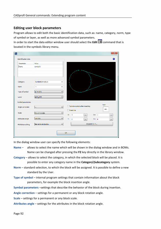
CADprofi General commands: Extending program content
Page 92
Editing user block parameters
Program allows to edit both the basic identification data, such as: name, category, norm, type
of symbol or layer, as well as more advanced symbol parameters.
In order to start the data editor window user should select the Edit command that is
located in the symbols library menu.
In the dialog window user can specify the following elements:
Name – allows to select the name which will be shown in the dialog window and in BOMs.
Name can be changed after pressing the F2 key directly in the library window.
Category – allows to select the category, in which the selected block will be placed. It is
possible to enter any category name in the Category\Subcategory system.
Norm – standard selection, to which the block will be assigned. It is possible to define a new
standard by the User.
Type of symbol – internal program settings that contain information about the block
parameters, for example the block insertion angle.
Symbol parameters –settings that describe the behavior of the block during insertion.
Angle correction – settings for a permanent or any block rotation angle.
Scale – settings for a permanent or any block scale.
Attributes angle – settings for the attributes in the block rotation angle.

CADprofi General commands: Extending program content
Page 93
Attributes editing – settings for block attributes edition.
Break line – enables/disables the possibility to insert the symbol into lines with automatic
interruption in the connection points. Conenction points are specified in the X–, X+
and Y-, Y+fields. In these fields user should enter the actual length of the cut in a
given direction from the insertion point for a symbol in a 1:1 scale. These values
can also be indicated in the drawing after clicking the button or after selecting
the All points X, Y… >. The vast majority of the symbols uses the intersection
points only in the X axis. One exception being the Cross symbols, which are
inserted at the intersection of two lines.
Dimensions – option that allows to scale the selected symbol independently in three main
directions (X, Y, Z). This option is only available for blocks created as a Scalable
object.
Base point

CADprofi General commands: CADprofi software translation tutorial
Page 94
CADprofi software translation tutorial
What is this chapter about?
CADprofi program possesses a very rich content, including a large number of national and
international standards, manufacturers' libraries etc. Many standards or libraries are
introduced to the program only in their original language or are translated only to some
languages. User can add his own translations, thanks to which it will be possible to obtain
BOMs and to easily create description in user native language.
It is also possible to share translations to other users and to send them to CADprofi, thanks to
which they will be included in next program versions.
This chapter describes how to translate CADprofi interface, module content (Mechanical,
Electrical, HVAC & Piping, Architectural) and manufacturers’ libraries.
Requirements
In order to prepare user own translations it is required to have CADprofi 9.21 (or later
version). It is also recommended to prepare translations in a Unicode software such as
AutoCAD 2007 (or later), BricsCAD V9 (or later).
Translations can be also prepared in exported PO format files. In order to edit these files, user
should install the POEDIT software (freeware), which can be downloaded directly from the:
http://www.poedit.net website.
The localization process cycle
The following drawing shows the CADprofi localization process cycle.
CADprofi context translation – translation of interface and
program content through the tools that are built in
the CADprofi program. User can add translations
on their own need or comprehensively translate
the whole program.
Verify – verify/translation in external files through the
POEDIT software. User can use this method to
cooperate with external translation office or
agencies.
Send to CADprofi – every user can send his translations as his
translation suggestions. After verification, they will
be added to the program in next CADprofi
updates.

CADprofi General commands: CADprofi software translation tutorial
Page 95
CADprofi context translation
This method makes it possible to translate by adding new text or by replacing an existing
translation directly in the CADprofi program.
User translations replace the standards program translations.
All translations made with this method are saved in the ‘UserData’ folder that is located in the
CADprofi main folder (default: C:\CadProfi\).
Translating the current command
It is possible to translate the current dialog window (options, settings) and the items
contained in this window. This is a convenient method, because user translates what he sees
at the moment on the screen.
Translation is made by using the dialog window that contains a translation table. This window
can be invoked from the context menu by pressing the Translate element or Translate
command option which is visible after right clicking on the mouse button on the selected
block.
Translate element – enables the translation of selected symbol/object name and its
additional information connected with this element (e.g. standard name).
Translate command – enables the translation of the interface of the currently opened dialog
window.
After using the Translate symbol/ Translate interface command a dialog window will appear
allowing to translate texts. This window contains the following items:
Name/No – describes a value like name, norm, parameter, etc.
Source – source text

CADprofi General commands: CADprofi software translation tutorial
Page 96
Standard translation – original translation in the currently selected language. This value will
be empty if it’s untranslated in the current language.
User translation – editable field that allows to add user translations.
Get source text ( ) – copies the selected source text to the User translation column.
Get standard translation ( ) copies the standard translation to the User translation
column.
Search ( ) – searches for the entered phrase in all three table.
Export – allows to export translations to exterior PO files for verification and optional sending
to CADprofi.
Context translation dialog window
In case of translating the command in the table only the texts that have been used by
program during the command execution will be available. Because of that it is recommended
to use all options that are available in the command before pressing the Translate command
option. Thanks to this the translation system will record all text and will make them available
for editing. It should be noted that some texts associated with the command are only
available after user closes the dialog window (e.g. after insertion of selected symbols into the
drawing). These texts will be also recorded and made available for editing, but only when user
runs the command once again.

CADprofi General commands: CADprofi software translation tutorial
Page 97
Procedures Context translation
6. Open any CADprofi dialog window.
7. Right click on a symbol which name you want to translate.
8. Choose the Translate element/Translate command to run the translation window.
9. (Optionally) Type in the command line CP_TRANSLATION to run the translation
window of the last used CADprofi command.
10. Change the texts that are in the User translation column.
11. Click the Save button to close and save changes.
12. All changes will be made after you reopen the CADprofi dialog window.
Translating the whole program
When translating contextual translations, the system record all texts that are used by the
program and make them available for translation. In this way it is possible to translate all
texts, which are visible when user "normally" uses the program. Apart from standard texts,
CADprofi program also contains many additional messages that appear sporadically (such as
messages about the improper program operation). The best way to translate these texts is
display a full table of texts in which user can easily find the text that requires translation.
The collection of all texts that are used in the program as well as the names of all symbols and
objects can be displayed with the Translate the program and Translate content that are
available in the modules main command: Architectural , HVAC & Piping , Electrical ,
Mechanical and Products library .
Notice
Program text interfaces are the same for all modules but each
module and each manufacturer’s library have got their own dictionary with their content translations.

CADprofi General commands: CADprofi software translation tutorial
Page 98
Export and translation verification
After translating the user interface, and the program content it is possible to export
translations to files in PO format and send them to CADprofi, as suggested translations,
thanks to which they will be available in future program updates.
Export to PO files
To export translations to PO files, user should press the Export button in the context
translation dialog window.
PO files generator dialog (export view)
The dialog window contains the following items:
Mode options – enables to choose between the Export and Import options.
Dictionaries – enables to select dictionaries to Export or Import.
Manufactures list – list of manufacturers dictionaries.
Tip
If you want to know more about the PO file format please visit the GNU ORG website.

CADprofi General commands: CADprofi software translation tutorial
Page 99
Main language – allows to select the translation language.
Extra languages – enables to choose two additional languages which translations will be
visible as suggestions during the work in the POEDIT program.
User translation only – options that allows to generate PO files that will contain only data
that was entered by the user during the context translation.
Mark as fuzzy text since version – allows to mark texts added from selected version number
as ‘fuzzy’. Thanks to this the person who prepares translations can quickly find new
texts that were introduced to CADprofi program since a particular version.
Generate template (*.pot) – allows to generate template files (*.pot files) which are needed
to update user previous PO files in POEDIT program.
Export – creation of PO files.
Open folder containing *.po files – Opens folder that contains PO files (by default
C:\CADprofi\X.x\Localization).
Verify *.po files with Poedit – allows to download and install the POEDIT program, which is
necessary to edit and verify PO files.
Send translations (*.po files) – creates a message using user default email program. PO files
(which will be treated as suggestions when creating new program version) should
be added to this message. CADprofi reserves the right to review and edit the
submitted translation.
Procedures Generating PO files
1. In the context translation dialog window press the Export button. The
Export/Import *.po files window will be opened.
2. Check/uncheck dictionaries that you want to export.
3. In the Main language section choose language that you would like to export.
4. (Optional) Choose additional languages.
5. (Optional) Select version number in order to check translations as “fuzzy”.
6. Agree to use your translations.
7. Click the Export button to close the window and create the PO files. Files will be
saved in the C:\CADprofi\X.x\Localization folder.
Notice
Agreeing for the use of translations is required in order to perform a PO files export.

CADprofi General commands: CADprofi software translation tutorial
Page 100
User translation export
1. In the context translation dialog window press the Export button. The
Export/Import *.po files window will be opened.
2. Select the Export CADprofi dictionaries to *.po files option.
3. Check/uncheck dictionaries that you want to export.
4. In the Main language section choose language that you would like to export.
5. Check the User translation only option.
6. Click the Export button to close the window and create the PO files. Files will be
saved in the C:\CADprofi\X.x\Localization folder. These files can be send to
CADprofi as translation suggestions.
Translation verification in the POEDIT program
POEDIT is a free, easy to use software that supports translations of PO files that were
exported from CADprofi.
POEDIT dialog window
The POEDIT dialog window contains the following elements:
Entries list – list of the translated (black), untranslated (dark blue), unsure ‘fuzzy’ (gold) and
errors (red) entries of the current *.po file.
Source text filed – not editable field with a source text.
Translation filed – editable field with a translated text.
Context field – information about the context of selected entry (where it is located within the
program, text type etc.).

CADprofi General commands: CADprofi software translation tutorial
Page 101
Notes for translators field – texts in additional languages, which were exported from the
CADprofi program. Translations in other languages may suggest in some cases the correct
translation of selected words or phrases.
Translations with the POEDIT program are very simple and intuitive. When editing texts, user
should pay particular attention for special characters that are described later in this
document.
All translations of the source language that were modified during the program development
can be marked as a ‘fuzzy’. In that case user can check the entry and decide if it’s still correct
or not. If the entry does not require correction it can be deselected by pressing the
button.
In another case user should add correction, which will also mark the selected entry as
translated.
User can use the "fuzzy" mark while he translates the PO files on his own..
PO files update
It is possible that during translation, a new version of CADprofi program will appear. In such
case, PO files will have to be updated. It can be solved in two ways.
The first option is to import to the updated program old *.po files (check the Import PO files
page 102). In this way, the already made translations will be added to the program. Re-
exporting PO files will include the already made translations as well as all texts which
appeared in new program version.
Another way is to update the PO files by using templates (*.pot files), that contain the current
CADprofi dictionary. Thanks tot his it is possible to add to the already translated texts, all the
texts that appeared in new program version.
Tip
Check the ‘Untranslated entries first’ option from the View menu to get all untranslated strings at the top of the list.

CADprofi General commands: CADprofi software translation tutorial
Page 102
PO files update process
Procedures Update of PO files
1. Update CADprofi software to the latest version.
2. Generate POT files using the Export option to dictionary files.
3. Run the POEDIT and open the *.po file that you want to update.
4. From the Project menu select the Update from .pot file option.
5. Select the *.pot file and press Open to update.
6. All changes will be applied.
Import of PO files
Import of PO files is intended for program development and collaboration with translation
agencies. For this reason, for standard user, the import PO files option is not available.
When importing PO files, all data is loaded into internal CADprofi dictionaries. User shouldn't
change this data, because an eventual update may update and overwrite all changes,
therefore the work may be lost.
It is completely different in context translation where all changes are saved in the ‘UserData’
folder. A CADprofi update does not interfere with the data, so any user extensions or settings
are automatically included in CADprofi program regardless of the installed version.

CADprofi General commands: CADprofi software translation tutorial
Page 103
Procedures Translation import
1. Run the CP_DICTIONARY command, after that an Export/Import *.po files dialog
window will be opened.
2. Select the Import *.po files to CADprofi dictionaries option.
3. Check/uncheck dictionaries that you want to import.
4. In the Select language section, select the language that you would like to import.
5. Select the Import/Do not import option in the What to do with ‘fuzzy’ texts
section (this option allows to specify if texts are marked as “fuzzy” should be
imported to program dictionaries).
6. Click the Import button to close the window and start the procedure.
Files to translate:
cp_string.po – program interface
dictionary_CpTools.po –CADprofi tools
dictionary_Arch.po – CADprofi Architectural content
dictionary_Electro.po – CADprofi Electrical content
dictionary_Sanit.po – CADprofi HVAC & Piping content
dictionary_Mech.po – CADprofi Mechanical content
Other PO files – manufacturers’ libraries dictionaries
Untranslatable words
Do not translate or change trademarks or program names such as:
CADprofi, AutoCAD, Bricscad, Cablofil etc.
phone numbers
email addresses (e.g. [email protected] or mailto:[email protected])
folder names and *.exe files (e.g. Common\cadprofi-connect.exe).
These texts should be copied to translations or they should be left with translations.

CADprofi General commands: CADprofi software translation tutorial
Page 104
Special characters
CADprofi program can be translated by editing PO files or by using the CADprofi Context
translation method. In both cases, you should pay attention to special characters. Their
presence is very important, and sometimes even critical User has to keep all special
characters in his translation in the right order and position just like in the source text. User
can only change the position of the percent ‘%’ character (e.g. %s, %d, %.10lf, %.12lg etc.).
Translation example:
English German
%s objects not found Keine %s Objekte gefunden
Meanings of special characters that can be found in CADprofi:
\n – the end of line
\\ – backslash
"" – means the ' "'
\[ – means the '<'
\] – means the '>'
\_ – means the space (for example at the end of the string)
%s, %d, %10lf, %12ls, %10lg, etc., – means the formatting string (%s = string, %d = value)
Notice
Special characters must appear in the same form in both translations and the source language. User can only change the position of the “%s” and “%d”
characters to keep the logical meaning of the sentence.
Tip
Both POEDIT and CADprofi Context translation tool have internal procedures to keep special characters correctness, so
pay attention for all messages displayed during the localization process.

CADprofi® Architectural


CADprofi Architectural: Architectural general commands
Page 107
CCAADDpprrooffii AArrcchhiitteeccttuurraall CADprofi Architectural helps user with creating construction plans, cross-sections and
elevation views. It also allows to create composite walls, insert windows and doors, create
architectural dimensioning, create descriptions and use objects from the furnishings and
furniture library. A unique program feature is the possibility to design evacuation and safety
plans. CADprofi Architectural is a sufficient addition to the base CAD programs, thanks to
which user can create and edit building blueprints much faster.
CADprofi Architectural in 2 minutes
Architectural general commands The Architectural command opens the dialog window from which we can choose the
appropriate commands from the Architectural module. This command has been prepared for
beginners. In the dialog window apart from the list of all commands we can also find a large
preview window that shows the outline of the selected function.
Architecturalcommand dialog window
Procedures Selecting the command
1. Run the Architectural command.
2. In the dialog window, expand the chosen category and select the needed
command.
3. Selected command will start after clicking the OK button.
CADprofi Architectural – main program commands
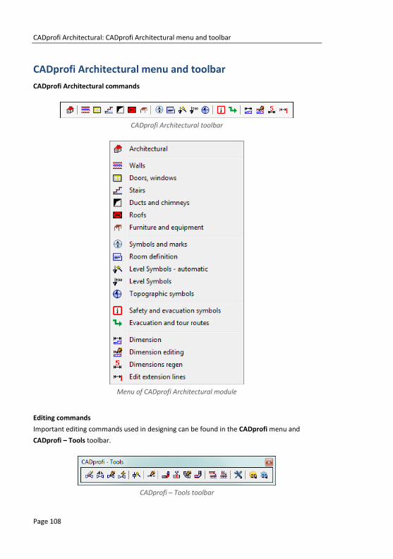
CADprofi Architectural: CADprofi Architectural menu and toolbar
Page 108
CADprofi Architectural menu and toolbar
CADprofi Architectural commands
CADprofi Architectural toolbar
Menu of CADprofi Architectural module
Editing commands
Important editing commands used in designing can be found in the CADprofi menu and
CADprofi – Tools toolbar.
CADprofi – Tools toolbar

CADprofi Architectural: CADprofi Architectural – introduction
Page 109
CADprofi Architectural – introduction Creating architectural drawings is associated with drawing walls, inserting both woodwork
objects and additional equipment as well as with describing drawings. CADprofi program
offers the designer appropriate commands, which makes work easier and faster. Many
options automate frequently performed actions, that's why it's very important to know how
the program works.
An important stage in the project creation is to describe the elements and rooms, so it is
possible to create various BOMs.
After installing the program, the default unit is millimeters. Architectural designs are usually
created in centimeters. User can change the design unit by running the CADprofi - Options
command and in the Units of drawing field select Centimeters.

CADprofi Architectural: Drawing walls
Page 110
Drawing walls In CADprofi program schematic walls are being drawn with lines that lie on appropriate
layers. Composite walls can contain several layers that represent walls by material (brick,
concrete etc.) or wall by purpose (load-bearing wall, insulation etc.).
Drawing single layer walls is possible after selecting the needed wall type and clicking the OK
button. Such a process however does not allow to change drawing settings and wall thickness.
These options are only available for walls that were added to the list that contain a wall
definition. This list also allows for drawing of composite walls.
Due to very large variety of materials used in the construction branch, when starting your
work with CADprofi it is recommended to define your own walls with your materials or
structural elements.
Walls dialog window
The Walls dialog window contains the following elements:
Wall types menu:
Define new – allows to add a new position to the list as a user wall
Copy – copies the selected wall with all its parameters, therefore creating an
element made by user. Copied lines may be edited.
Edit – opens the edit properties window of a selected user created wall
Delete – deletes the selected wall from the list.

CADprofi Architectural: Drawing walls
Page 111
Add to favourites – adds the selected line to the *Favourites* (check page
122) list.
Add element to a list – adds the selected line to the List of wall layer
parameters.
Menu of wall layer parameters – allows to manage the content of the selected walls list.
Move selected rows down – moves the selected wall one position down.
Move selected rows up – moves the selected wall one position up.
Remove selected rows – deletes the selected wall from the list.
Copy selected rows – copies the selected wall and adds it to the list.
Save as a structural wall – allows to save the current list of selected walls as a
structural wall.
Wall layer parameters – provides a summary of wall layers.
Thickness – specifies the thickness of specified layer in a composite wall.
Edge of drawing and offset – options that are used to determine the way of wall drawing and
the offset.
Left/Center/Right – drawing the wall with the axis or with an edge of the indicated
points.
Offset – an offset of the drawn lines from the points that are actually indicated in
the drawing.
Pop-up menu – options menu for selected
element/category which is available by clicking
the right mouse button. Commands included in
the menu are similar to the commands available
on the dialog window toolbars.
Wall axis – drawing direction
Wall left edge
Wall right edge

CADprofi Architectural: Drawing walls
Page 112
Procedures Drawing the wall
1. Run the Walls command.
2. In the newly opened dialog window pull-down the category that contains the
desired wall kind.
3. Select the desired wall type and click the Add element to a list button or
double click on it in order to put it on the list.
4. (Optional) Repeat steps 2 and 3 in order to add more lines to the list.
5. (Optional) Using the Copy selected rows , Remove selected rows buttons
add or remove the selected layer from the list.
6. Specify the thickness for each wall layer.
7. (Optional) Using the Move selected rows down /Move selected rows up
buttons change the order of the lines on the list.
8. Specify the edge of drawing and offset.
9. Click the OK button in order to start drawing the wall.
10. Specify the starting point and next walls segment points (e.g. P1, P2, P3, P4). In
order to finish drawing press the Enter or Esc key. It is also possible to close the
command with the Close option (C key), thanks to this program will draw the last
segment that will connect itself with the first segment of our drawn wall.
Drawing walls

CADprofi Architectural: Drawing walls
Page 113
Procedures Drawing a wall installation with an offset
1. Run the Walls command.
2. Select the desired wall installation type and click the Add element to a list .
3. Specify the wall thickness.
4. Specify the edge of drawing as „left” and the offset, as e.g. 360 cm.
5. Click the OK button in order to start drawing the wall.
6. Specify the starting and the end points (P1, P2). The wall will be drawn with a
specified distance from the indicated points.
7. Finish the drawing with the Enter or Esc key.
Hint
Drawing with an offset can be used when drawing wall installations.
Offset Drawn wall
(left edge)

CADprofi Architectural: Drawing walls
Page 114
Edit walls materials
CADprofi allows users to define new walls types and to edit them.
Edit walls materials dialog window
The dialog window contains the following items:
Name – name of edited wall layer.
Text notation – text marking for lines used as an ending of layer’s name in the extended layer
structure (e.g. „concrete” wall type can lie on a 2DA_WAL_Bet layer).
Category –category in which the selected wall type will be saved.
Default wall thickness – wall thickness that is used as a default value when the selected wall
layer is being added to the wall layer parameters list.
Wall layer parameters – CAD settings for the layer, on which the selected wall type will be
drawn. User should specify the color and both the line width and type for the
appropriate layer.
Notice
It is recommended to use „unique values” of text notations in order to ensure proper recognition of lines by CADprofi.

CADprofi Architectural: Drawing walls
Page 115
Procedures Creating new wall types in the database
1. Run the Walls command.
2. Click the Define new button in order to add a new wall type to the existing
database. New element will be added to the *User* category. A new Edit window
will open, in which user will be able to specify all wall parameters.
3. (Optional) Select an existing line and click the Copy button to create a new
item. Selected line will be used as a template.
4. Click the Edit button in order to specify newly created wall parameters.
Edit wall type’s data
1. Run the Walls command.
2. (Optional) If the wall type that you want to edit is located on the list of wall layer
parameters, then you will need to remove it first from the list, to do this, select
the element and click the button.
3. In the *User*category select the wall type that you would like to edit.
4. Click the Edit button. A new edit dialog window will open.
5. (Optional) Specify the wall type Name.
6. (Optional) Specify the Text notation for the CAD wall layer (not recommended, if
the element has been already used in the drawing).
7. (Optional) Specify the Category.
8. (Optional) Specify the default thickness for the selected wall type.
9. (Optional) Specify the wall layer parameters: type, color and line thickness.
10. Click the OK button to accept the changes.
Notice
If user changes the parameters of CAD wall layer, which was previously added to the drawing, then in order to update it,
user will have to draw a new wall segment with new settings.
Changing the text notation for walls that have already been
inserted in the drawing will make them unknown for CADprofi.

CADprofi Architectural: Doors, windows
Page 116
Doors, windows The Doors, windows command allows to insert doors and windows in both plan and view. For
each objects databases are available that contain woodwork elements. All objects in the
library are parametrical objects. It means that user has the possibility to specify all the
dimensions when inserting objects to the drawing. This feature gives user a lot of
opportunities because he is able to specify dimensions on his own, even for elements that are
not in the standard program databases. If user inserts windows and doors in plan then he has
to specify the wall thickness, in which he wants to insert the element. Providing the correct
wall thickness will allow to automatically hide the wall lines, in which the element will be
inserted. Application is able to automatically detect the thickness of wall that was indicated
by the user on condition that all the lines (of the multi-layered wall) are parallel and the total
thickness does not exceed 600 mm.
For thicker walls or the ones that don't meet the requirements user must specify the B
dimension during insertion or by using the Insert option (specify all dimensions).
Doors windows dialog window
The dialog window contains the following items:
List of categories – displays a list of available elements grouped in categories and
subcategories.
Detailed list – contains a list of available element types with various dimensions.

CADprofi Architectural: Doors, windows
Page 117
Preview – displays the preview of the currently selected element. Right-clicking on the
preview window will zoom the view.
Sort – enables/disables categories alphabetical order.
View and insertion point – view selection and object insertion points. For all library objects a
primary view is available (mostly 2D). Additional views are available only for some
objects (e.g. Internal window jamb and External window jamb are available only
for plan windows).
Number/Mark – data assigned to inserted element, it is used during insertion of
Carpentry symbols (check page. 127).
Insertion point – possibility to choose the objects base point (insertion point). Insertion
points are marked on the preview as P1, P2 etc.
Object style – options that allow to specify the object style and the level of object detail.
Object style dialog window
Insert as block –allows user to insert an element that is exploded into component
parts or a one single object (block).
With attributes – enables/disables adding of attributes to the inserted object.
Axes – enables/disables an option to draw axis in the inserted object.
Hidings – enables/disables drawing elements that are hidden in an object.
Wipeout (covers) – enables/disables addition to the inserted elements Covers
(WIPEOUT) type objects.
Details, hatch – enables/disables drawing of hatches and object details such as
holes in the flanges, arrows that indicate the direction flow and others.
Texts– enables/disables drawing of potential texts in objects.
Notice
All „Object style” settings will be remembered and used when
user runs the command again.

CADprofi Architectural: Doors, windows
Page 118
Details – button that allows to specify dimensions for details that are visible in certain views
such as Internal window jamb and External window jamb. Clicking the button will
open a dialog window with visible current value dimensions.
Parameters dialog window
OK – closes the library and allows to insert the object into the drawing.
Insertion options – expands the list of available insertion options:
Insert (specify style for object) – inserts selected object with a possibility to
change options in the Object style dialog window.
Insert (specify all dimensions) – inserts selected object with possibility to specify
all dimensions that can be edited.
After selecting this option a Parameters window will appear allowing user to
specify values for each dimension. It is also possible to determine dimensions
directly from the drawing. In order to do so, user has to activate the value edit
field and then click the Pick distance button. It is also possible to save the user
dimensions by Creating and extending the user type of series Creating and
extending user type of series (check page 88).
Hint
By default, in the "Parameters" window displays the
dimensions of the object selected in the command main dialog window.

CADprofi Architectural: Doors, windows
Page 119
Procedures Inserting doors and windows
1. Run the Doors, windows command.
2. In the dialog window choose the needed element (e.g. window projection).
3. (Optional) Select View for selected object, its Insertion point and and specify the
Object style options.
4. Click the OK button in order to insert the element in the drawing.
5. (Optional) With the use of the button expand the list of insertion options and
select Insert (specify all dimensions), in order to specify the object dimensions.
6. Indicate the insertion point. If the selected point will be located on a wall that was
created with CADprofi command (P1) then application will automatically
determine the required block width and allow to slide the window along the line.
7. Specify the block location point (P2), use the Reference (R), in order to measure
the length from any point.
8. (Optional) Indicate the rotation point for the inserted object.
9. (Optional) Specify the wall thickness for the inserted window.
10. (Optional) During the insertion of doors on projections indicate the P3 point that
defines the block insertion side.
Hint
Use the Quick edit, command to change the windows and doors
insertion side. Use the Insert (specify all dimensions) option in order to define
the wall thickness before inserting the block.
Doors, windows
Inserting doors and windows without WIPEOUT
If the doors or windows are being inserted in the wall without hidings (WIPEOUT), then after
their insertion it may be needed to "cut" the wall lines with the help of the _TRIM command.
View after inserting a window View after the wall is „cut”

CADprofi Architectural: Furniture and equipment
Page 120
Furniture and equipment The Furniture and equipment command possesses many objects that are used in
construction projects. Furniture, sanitary equipment, home appliances and many more
objects are available. This command also contains additional architectural elements such as:
ventilation and exhaust, culverts and others.
Objects available in this command are parametrical objects, for which user can specify all
dimensions. Field used for specifying the dimensions are available in the dialog window. It is
also possible to indicate dimensions from the drawing after clicking the Pick distance . For
some objects, typical databases have been prepared that allow to quickly select typical
elements after clicking the button.
Different wardrobes dimensions from the
databases of typical dimensions
Changing the dimensions for CADprofi objects is equivalent to rebuilding the block, not just
with changing the scale in the X and Y directions. Thanks to this always the correct view is
obtained and the specific elements (such as handles, holes etc.) are not deformed.
An example of a chest of drawers with a 900 and 1500 mm widths

CADprofi Architectural: Furniture and equipment
Page 121
Furniture and equipment dialog window
The Furniture and equipment dialog window contains the following items:
Tools menu:
Define new – allows to add a new element to the database. Read more about it
in the Defining user blocks (check page 89).
Edit – allows to Editing user block parameters (check page 92).
Add to favourites – copies symbol to the *Favourites* (check page 122)
Delete – deletes the selected symbols from the *Favourites* category.
Pop-up menu– options menu for the selected symbol,
which is available after right clicking on the
mouse button on the selected symbol.
Commands in this menu are similar to the tools
menu.
Categories tree – a set of all categories and symbols in the library, shown as a pull-
down tree. User can customize the display order by using the Sort option.
Thumbnail view – displays the content of currently selected category as thumbnails.
Preview – displays the preview of the currently selected element. Right-clicking on the
preview window will zoom the view.
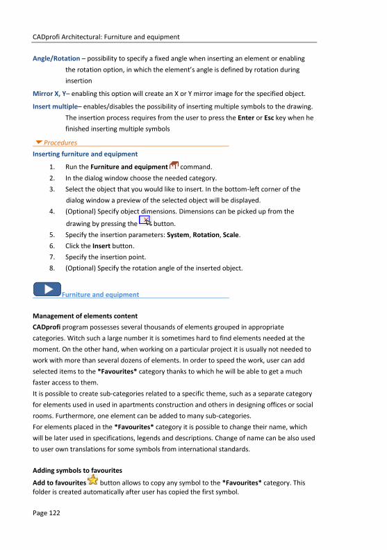
CADprofi Architectural: Furniture and equipment
Page 122
Angle/Rotation – possibility to specify a fixed angle when inserting an element or enabling
the rotation option, in which the element’s angle is defined by rotation during
insertion
Mirror X, Y– enabling this option will create an X or Y mirror image for the specified object.
Insert multiple– enables/disables the possibility of inserting multiple symbols to the drawing.
The insertion process requires from the user to press the Enter or Esc key when he
finished inserting multiple symbols
Procedures Inserting furniture and equipment
1. Run the Furniture and equipment command.
2. In the dialog window choose the needed category.
3. Select the object that you would like to insert. In the bottom-left corner of the
dialog window a preview of the selected object will be displayed.
4. (Optional) Specify object dimensions. Dimensions can be picked up from the
drawing by pressing the button.
5. Specify the insertion parameters: System, Rotation, Scale.
6. Click the Insert button.
7. Specify the insertion point.
8. (Optional) Specify the rotation angle of the inserted object.
Furniture and equipment
Management of elements content
CADprofi program possesses several thousands of elements grouped in appropriate
categories. Witch such a large number it is sometimes hard to find elements needed at the
moment. On the other hand, when working on a particular project it is usually not needed to
work with more than several dozens of elements. In order to speed the work, user can add
selected items to the *Favourites* category thanks to which he will be able to get a much
faster access to them.
It is possible to create sub-categories related to a specific theme, such as a separate category
for elements used in used in apartments construction and others in designing offices or social
rooms. Furthermore, one element can be added to many sub-categories.
For elements placed in the *Favourites* category it is possible to change their name, which
will be later used in specifications, legends and descriptions. Change of name can be also used
to user own translations for some symbols from international standards.
Adding symbols to favourites
Add to favourites button allows to copy any symbol to the *Favourites* category. This folder is created automatically after user has copied the first symbol.

CADprofi Architectural: Furniture and equipment
Page 123
Changing the element name
Initially, each copied symbol receives the default
name from the original item.
In order to change the element’s name user
should first select it and then press the F2 button
to activate the edition mode.
Changing category
In order to change or define a new category,
click the right mouse button on a desired
symbol and from the context menu choose the
Change category option.
In the dialog box, user can select an existing
category or enter a new category name. After
accepting, selected element will be moved to
the defined category.
CADprofi application allows to create many
copies of each element and it is possible to
place them in different categories. Thanks to
this user can create categories that group
elements of a specified type or the most
common used elements for a given industry
type.
Changing the category or many symbols
If user is editing a symbol in his native
category in which there are many elements,
then CADprofi application will change
category for all these elements.
Deleting elements
It is possible to delete elements from the *Favourites* category. To do so, select the element
and choose the Delete option from the dialog window.
Notice
Changed name will be visible in tables and descriptions that are created with the „Bill of materials” (check page 46) command.

CADprofi Architectural: Stairs
Page 124
Stairs The Stairs command allows to quickly create stairs with specified parameters. Both one-flight
and landing are available. From these elements it is possible to create stairs with any number
of cases.
Stairs dialog window
Basic functionality and options regarding work with objects are described in the Furniture and
equipment (check page 120) chapter. Additional options that are included in the command:
Preview and parameters – an example preview with element parameters.
n1 – number of treads.
W1 – total stairs width.
S – tread depth.
H – tread height.
A – first thread height.
B – last thread height.
Z – „undercut” tread value.
Undercut „Z” – enables/disables drawing of „undercut” for treads.
Height section – the actual value of the stairs cross-section view. The staircase
view (both normal and treads hiding) depends on this height.

CADprofi Architectural: Stairs
Page 125
Base point – the choice of object insertion points (P1, P2 on the preview).
Text height – text height that is used for stairs description.
Notations – specifies the stairs notation type.
The list of available stairs notations.
Selecting an empty field located on the end of the
list, means that no notation will be inserted.
Procedures Inserting stairs
1. Run the Stairs command.
2. In the Stairs dialog window on the List of elements click on a stair type that you
would like to insert into the drawing.
3. (Optional) Select the stair type from the list of available stair’s preview located on
the top of the window.
4. In the preview window specify parameters for stairs that are going to be inserted.
5. (Optional) Change or indicate the rotation angle.
6. (Optional) Enable the Rotation function in order to specify the rotation angle when
inserting the block.
7. (Optional) Enable/disable the Insert multiple option
8. Click the Insert button in order to insert the element into the drawing.
9. Indicate the insertion point for block.
10. (Optional) Indicate two points that specify the block rotation angle.
Inserting stairs
Double staircase created from available elements

CADprofi Architectural: Roofs
Page 126
Roofs Roofs command allows to quickly insert to the drawing the selected type of roof with user
specified dimensions. During the block insertion, application automatically calculates the
actual slope area, and its value is available in attributes.
„Roofs” dialog window
Basic functionality and options regarding working with objects are described in the Furniture
and equipment (check page 120) chapter. Additional options that are included in this
command:
Preview and parameters – a sample preview and parameters of selected element.
W1, L1 – building dimensions.
K1, K2 – overhangs’ length.
L2 – ridge length.
h – roof height.
Slope angle – the value of the main roof slope.
Calculate slope from height – this option allows to automatically calculate the
slope with inclusion of the specified height.
Base point – allows user to select the object insertion points (on preview: P1, P2).
Text height – text height for roofs’ markings.
Marking selection – allows selection between Slope and
Pitch expressed in percentage.

CADprofi Architectural: Symbols and marks
Page 127
Symbols and marks CADprofi possesses several categories architectural marks symbols. Most of these symbols
are available in the Symbols and marks command. To obtain a quicker access for certain
marks, they have been also added to additional commands e.g. Level symbols or Topographic
symbols.
One of the categories available in the Symbols and marks command are the woodwork
elements marks. These symbols allow to specify number, label and dimensions of described
element. These data can be later used when creating BOMs and obtaining a variety of
information about the project. In order to describe various objects user should use
appropriate symbols.
Example: for windows inserted into the drawing horizontally, user should use appropriate
symbols and for windows inserted with a 90 degrees angle - different symbols.
When describing many objects it's convenient to select the Insert multiple option.
Symbols and marks

CADprofi Architectural: Level Symbols - automatic
Page 128
Level Symbols - automatic The Level Symbols - automatic command allows to insert height points with automatic filling
of elevation values for indicated points.
Level Symbols – automatic dialog window
Options available in this dialog window have been described in previous chapters (check page
120). Additional options included in this command:
Text height – specifies the marks text height and scale. User can enter a value or indicate it
from the drawing (indicate two points).
Precision of dimensions – defines the decimal number of the ordination values in the symbol
that’s going to be inserted.
Unit – determines the unit, which will be changed into the elevation value in the inserted
symbol. CADprofi program determines the actual ordination value in accordance
with the currently drawing units that were set in the CADprofi - Options command.
The Unit option allows to recount the actual height into one of available units.
Separator – determines the decimal number of ordination value.
Format ‘+/–‘ – determines if the positive ordination values should be preceded with a „+”.

CADprofi Architectural: Level Symbols - automatic
Page 129
Level – determines the reference point of the symbol ordination value. The following ways to
determine the coordinate system are possible:
Auto – calculates the ordination value in regards with the previously set Reference
point.
Auto WCS – calculates the ordination value from the 0.0 point of the World
Coordination System.
Auto UCS – calculates the ordination value from the 0.0 point of the User
Coordination System.
Reference point – additional text that informs for example about the above sea level height
or the ground foundation height.
Procedures Inserting the reference point
1. Run the Level Symbols - automatic command.
2. In the dialog window select the Reference point.
3. (Optional) Specify the symbol text height.
4. (Optional) Specify the following options: Precision, Unit, Separator and Format ‘+/–‘.
5. Choose the coordination system, which will specify the point Level or enter the
value manually. Reference point is a benchmark for other height points that's why
this point Level is specified as „0”.
6. Click the Insert symbol button to insert a symbol into the drawing.
Inserting an automatic level symbol
1. Run the Level Symbols - automatic command.
2. In the dialog window select the appropriate level symbol marking.
3. (Optional) Specify the symbol text height.
4. (Optional) Specify the following options: Precision, Unit, Separator and Format
‘+/–‘.
5. Specify the Level, from which the current level will be count. If the level should be
counted from the reference point select the Auto option.
6. (Optional) Define or select the Reference point for the selected point.
7. Click the Insert symbol button to insert a symbol into the drawing.
Symbols and marks
Notice
Only one reference point can be added to the drawing, making an attempt to insert the next point will display an appropriate message and will allow to replace the old reference point.

CADprofi Architectural: Level Symbols
Page 130
Ways to specify the level: Reference point, WCS and UCS
Level Symbols The Level Symbols command allows to insert height points. The only difference regarding the
Level Symbols-automatic lies in the fact than in the Level Symbols user can manually specify
the level symbol and any additional values.
Procedures Inserting a level symbol
1. Run the Level Symbols command.
2. In the dialog window select the appropriate level symbol marking.
3. (Optional) Specify the symbol rotation angle.
4. (Optional) Specify the symbol text height.
5. Specify the Level value, optionally choose additional +/– markings.
6. (Optional) Specify or choose the Reference point for the chosen point.
7. (Optional) In the symbol preview enable/disable an option that allows to draw a
bottom line in description.
8. Click the Insert symbol button to insert a symbol into the drawing.
Reference point
UCS
WCS

CADprofi Architectural: Topographic symbols
Page 131
Topographic symbols The Topographic symbols command allows to insert into the drawing many different symbols
such as: arrows, cardinal direction symbols, slopes and others.
Topographic symbols dialog window
Options available in this dialog window have been described in previous chapters (check page 120).
Procedures Inserting topographic symbols
1. Run the Topographic symbols command.
2. In the dialog window select the appropriate symbol.
3. (Optional) Specify the symbol rotation angle. You can enter the value or press the
button in order to indicate two points from the drawing that define the
rotation angle.
4. (Optional) Select the Rotation option in order to specify the rotation angle when
inserting a block into the drawing.
5. (Optional) Specify the symbol size by entering the scale value or press the
button in order to get the scale from another symbol that’s located in the drawing.
6. (Optional) For certain symbols you can specify additional parameters, e.g. for slope
symbols you can specify the slope value in percent or in degrees.
7. Click the Insert symbol button to insert a symbol into the drawing.
Symbols and marks

CADprofi Architectural: Room definition
Page 132
Room definition In CADprofi it is possible to define and describe rooms or other usable areas. Program can
automatically find boundaries and calculate their surface. It is also possible to manually define
the rooms or to take over "foreign" boundaries (closed polylines), which is useful when
working on architectural drawings that are made outside of CADprofi.
Program also allows to create room specifications, that's why when user defines a room, he
should also specify their name, number and additional data.
Room definition dialog window
Options available in this dialog window have been described in previous chapters (check page
120). Additional options included in this command:
Number – defined room number. This field is automatically filled with a first free number.
Thanks to available buttons, user can choose between first available free number
and a next number . This field can be filled with any value.
Information about defined room – a collection of information about defined area. These data
will be saved as a collection of attributes of selected room label. The Browse
button allows to select typical data for rooms that have specific purpose.
Real surface area – field that shows information about actual room surface area.

CADprofi Architectural: Room definition
Page 133
Calculating the floorage area:
Program automatically calculates floor area of defined room. Typically, construction projects
do not include the plasterwork thickness. Therefore, when calculating floor area program can
take into account "plasterwork" deductions.
It is also possible to manually set the floor area (e.g. if it's needed to deduct the area under
the low-sloped roofs in attics). When calculating the surface it is very important to have the
same design unit as the one that we used in the drawing. User can specify the area format
with the use of Precision and Floor unit.
Ways to define rooms:
After specifying the parameters user should define them on the drawing. Button that is used
for it has got a drop-down list that allows to select a method of determining the boundaries:
Define room (automatically) – this option will automatically search for a closed
area, in which the room has been defined. This method can be used when all walls
have been drawn by CADprofi program and they haven't been interrupted for
example when inserting doors or windows (in CADprofi program there is no need
to interrupt the walls, if windows and doors are being inserted with hiding objects
- WIPEOUT).
Automatic search for room boundaries can also be used even if the walls weren't
drawn by CADprofi program on condition that they are placed on the
„2DA_WAL_” layer.
Select boundary – this option allows to indicate a boundary (closed polyline),
which will be acquired by CADprofi program as a room. This option is often used
when working on "foreign" construction drawings, in which the boundaries that
restrict the room are already drawn.
Notice: in CAD programs polyline is closed if user completed its drawing by using
the Close command. This status can be checked in the CAD properties window.
Outline a room – possibility to drawn a boundary through manual outline. User
should indicate all room corners. In order to finish this command user should press
Enter or right mouse button.
Dividing line of rooms – draws the room dividing line. Diving lines are being
inserted on a layer which is disabled by default in printing. This line allows to add a
logical division or a room without need to draw any additional walls.
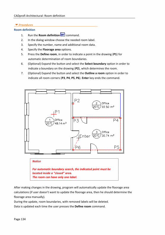
CADprofi Architectural: Room definition
Page 134
Procedures
Room definition
1. Run the Room definition command.
2. In the dialog window choose the needed room label.
3. Specify the number, name and additional room data.
4. Specify the Floorage area options.
5. Press the Define room, in order to indicate a point in the drawing (P1) for
automatic determination of room boundaries.
6. (Optional) Expand the button and select the Select boundary option in order to
indicate a boundary on the drawing (P2), which determines the room.
7. (Optional) Expand the button and select the Outline a room option in order to
indicate all room corners (P3, P4, P5, P6). Enter key ends the command.
Notice
For automatic boundary search, the indicated point must be
located inside a "closed" area.
The room can have only one label.
After making changes in the drawing, program will automatically update the floorage area
calculations (if user doesn't want to update the floorage area, then he should determine the
floorage area manually).
During the update, room boundaries, with removed labels will be deleted.
Data is updated each time the user presses the Define room command.

CADprofi Architectural: Architectural dimensioning
Page 135
Architectural dimensioning
Dimensions
The Dimension command is used for easy dimensioning with styles that suit the construction
projects. It is possible to dimension in model or paper area. This command allows to freely
customize the existing styles, or define a user own dimensioning style. What is more, drawing
can be prepared in a different unit (e.g. mm) and dimensions can be created in a different
unit (e.g. cm).
Program also allows to change the "normal dimensioning" into "architectural dimensioning".
Dimension dialog window
The Dimension dialog window contains the following elements:
Dimension style – list of CADprofi styles and styles created by the user.
Get style from drawing – allows to choose a dimension style by selecting an
object from the drawing.
Create a new dimensioning style – creates a new dimension style.
Change parameters of selected style – enables the possibility to edit the selected
style settings. Changes will only be made in the selected style.
Appearance of dimensions settings – a collection of settings that define the selected style:
Arrow – allows to select the type of the main dimension line endings of the
selected style.

CADprofi Architectural: Architectural dimensioning
Page 136
Length of an extension line – extension line length measured in drawing units. This
value is scaled accordingly to the set text scale.
Additional parameters – opens the dialog window that contains additional settings
related with dimensions appearance.
Additional parameters
Settings dimensions in layouts – during dimensioning in paper area (sheets) program will
calculate the dimensions accordingly to the viewport scale. Therefore it is needed
to enter the viewport (paper) scale or to get it from the indicated viewport in the
sheet.
Dimensions unit – program calculates dimensions from the current unit into the selected unit
(below the current drawing unit is being displayed). Basic units such as mm, cm, m
and inches are available. Additional option "m/cm" work in a specific way - if the
dimension is less than one meter then the dimension text only includes
centimeters (e.g. for 87,5 cm the dimension will include the 875 text), if the
dimension has got more than one meter, then the dimension text will include both
meters and centimeters (e.g. for 187,5 cm the dimension will include the 1.875 m
text).
Size and style of the text – settings used for the dimensions text display.
Decimal separator – symbol oddzielający miejsca dziesiętne.
Superscript (for incomplete centimeters) – enables/disables the display of decimal
values as a superscript.
Dimension tolerance – a value to which all dimensions will be rounded up.
Text style – gives the possibility to choose one of available text styles.

CADprofi Architectural: Architectural dimensioning
Page 137
Text height – text height in mm in printings.
Text scale (model) – printing scale for selected drawing. This option is used only
for appropriate text adjustment.
Always show dialog – enables/disables the display of the dialog window after pressing the
Dimension command. If the window is not being displayed and it is necessary to
change the settings then user can enable the dialog window with the Settings
option (S key).
Dimensioning is carried out in two stages:
In the first stage user should specify two points that will determine the dimension
string position (P1, P2).
In the second stage user should indicate additional measured points (P3, P4 etc.).
In one string user can specify any number of dimensions. In order to complete the
dimensioning process press the Esc key or click the right mouse button.
After running the command again user can add additional dimensions to the drawing. When
determining the dimension string user should indicate the side points (P1, P2) of the previous
dimensioning. In this way user can attach additional strings. After indicating the string
location, user should indicate additional measured points (P3–P8).
Dimension display (building external dimensions)
Dimension string position

CADprofi Architectural: Architectural dimensioning
Page 138
After running the command twice the following result appears:
Procedures Architectural dimensioning
1. Run the Dimension command.
2. (Optional) If the dialog window didn’t appear, select in the command line the
Settings option (S key).
3. In the dialog window select the dimensioning style.
4. (Optional) Click the Create a new dimensioning style , to add a new style to the
current drawing.
5. (Optional) Enable the option Change parameters of selected style, in order to
make changes in the dimension styles settings.
6. Click the OK button to close the dialog window and start dimensioning.
7. (Optional) In the command line select the Object option (O key) and indicate an
existing dimension from the drawing. It will allow to continue an existing
dimension string.
8. Indicate the first point, where the dimension string will be located.
9. Indicate the second point, where the dimension string will be located.
10. Indicate the first and second measured point. The first dimension will be created.
11. (Optional) Indicate additional points in order to add additional dimensions to the
string.
12. Press the Esc key or click the right mouse button to end the command.
Architectural dimensioning
Notice
After editing the drawing, for example when user stretches the dimensions it is needed to regen the dimension texts. Regeneration is performed by running any CADprofi
dimensioning command.

CADprofi Architectural: Architectural dimensioning
Page 139
Dimensions editing
The Dimensions editing command is used for changing the style of existing dimensions that
have been already added to the drawing. User can select or create a new style and then and
afterwards indicate dimensions on the drawing for which the selected style will be applied. In
this way it is possible to replace "normal" dimensioning into architectural dimensioning.
Procedures Dimensions editing
1. Run the Dimensions editing command.
2. In the Dimensions editing dialog window select the dimension style that you
would like to apply to existing dimensions.
3. (Optional) Click the Create a new dimensioning style , to add a new style to the
current drawing.
4. (Optional) Enable the option Change parameters of selected style, in order to
make changes in the dimension styles settings.
5. Click the Replace button to close the dialog window and enable the dimensions
selection.
6. Select dimensions, which style you would like to replace.
7. Click the Enter key or right mouse button to make the changes and end the
command.
Normal dimensioning
View after changing the normal dimensioning into architectural dimensioning

CADprofi Architectural: Architectural dimensioning
Page 140
Dimensions regen
The Dimension command allows to change dimensions styles. These changes will apply to
new dimensions, but won't affect dimensions that already exist in the drawing. In order to
apply changes to all dimensions it is required to run the Dimensions regen command. .
This command also updates dimension texts after editing the dimensions geometry (e.g.
during dimension stretch).
This command does not display any dialog window, therefore any results of this command
can be read only in the CAD program command line.
Edit extension lines
In architectural dimension strings the side dimension lines are usually used to "link" them
with additional strings. Therefore, the side extension lines should be longer than other lines.
The Edit extension lines command is used to shorten or lengthen the dimension side
extension lines. The need to conduct such an operation may be needed when user makes
various editing changes that regard dimensions such as: deleting, moving, dimensions copying
etc.
Procedures Edit the length of extension side lines
1. Run the Edit extension lines command.
2. Click on any dimension that was created with CADprofi in order to
shorten/lengthen the side extension line.
3. (Optional) Click on next dimension to edit it.
4. Press the Esc key or click the right mouse button to end the command.
View before and after the side extension lines were lengthen

CADprofi Architectural: Safety and evacuation symbols
Page 141
Safety and evacuation symbols The Safety and evacuation symbols command allows to insert to the drawing a variety of
markings used in evacuation, fire safety and other plans. This command also contains public
information symbols as well as many more.
Safety and evacuation symbols: dialog window
Options available in this dialog window have been described in previous chapters (check page
120). Additional options included in this command:
With frame – enables/disables drawing a frame around the inserted symbol. The frame can be
useful, for example, in case of necessity of hatching the area where the symbol is
located. Thanks to the frame the symbol won't be blended with the hatched area.
Safety and evacuation symbols
Notice
Many "evacuation" symbols contain small details. In order to
enhance the details of these symbols a special outline of them is placed on the CPCOLOR_255 layer. During printing user must adjust both the width and colour of this layer. Alternatively,
user can disable this layer, so it won't be printed.

CADprofi Architectural: Evacuation routes
Page 142
Evacuation routes The Evacuation and tour routes command allows to draw and edit evacuation and fire safety
routes as well as other routes such as: museum and gallery sightseeing tours etc. At the end
of the route user can insert arrows that indicate directions.
Evacuation and tour routes dialog window
The dialog window contains the following items:
Drawing mode – selection of route drawing or editing mode.
Route style – selection of route type. Each route type is created on a separate layer.
Route options – gives the possibility to specify route width and the dimensions of arrows.
Draw arrow at the beginning/end of a route – enables/disables drawing of arrows at the
route beginning/ending.
Always show dialog window – enables/disables the display of dialog window after running
the Evacuation and tour routes command. If the window is not displayed then the
route will be drawn accordingly to the previously selected settings. In order to
enable the display of dialog window user should select the Settings option (S key).
Procedures Drawing routes
1. Run the Evacuation and tour routes command.
2. In the dialog window select the Route drawing mode.

CADprofi Architectural: Evacuation routes
Page 143
3. Select the Route style, e.g. „Evacuation route”.
4. (Optional) Specify the arrow width/height settings.
5. (Optional) Enable/disable the draw arrow at the beginning/end of a route option.
6. Press the OK button to close the dialog window and start drawing the route.
7. Specify next points for the route. You can finish the drawing by pressing the Enter
key or clicking the right mouse button.
Editing routes
1. Run the Evacuation and tour routes command.
2. In the dialog window select the Route edit mode.
3. Select the Route style, e.g. „Evacuation route”.
4. (Optional) Specify the arrow width/height settings.
5. (Optional) Enable/disable the draw arrow at the beginning/end of a route option.
6. After pressing the OK button select the route to which you would like to apply new
settings. The indicated route will be changed.
Evacuation routes
An example of an evacuation route and evacuation and fire safety symbols.

CADprofi Architectural: Evacuation routes
Page 144

CADprofi® HVAC & Piping


CADprofi HVAC & Piping: HVAC & Piping general commands
Page 147
CCAADDpprrooffii HHVVAACC && PPiippiinngg HVAC & Piping program helps with designing installations in both general and industrial
construction. With many types of predefined and editable lines, this module allows you to design
any type of installations such as: heating, water & sewage, gas, medical, fire safety, ventilation, air
conditioning, refrigeration and other technical installations in construction and industry.
Particularly important for users are functions that support the designing of schemes, strand
diagrams, isometrics, plans and sections that allow user to use only one tool to create the entire
project.
CADprofi HVAC & Piping in 2 minutes
HVAC & Piping general commands The HVAC & Piping command opens the dialog window from which we can choose the
appropriate commands from the HVAC & Piping module. This command has been prepared for
beginners. In the dialog window apart from the list of all commands we can also find a large
preview window that shows the outline of the selected function.
HVAC & Piping command dialog window
Procedures Selecting the command
1. Run the HVAC & Piping command.
2. In the dialog window, expand the chosen category and select the needed command.
3. Selected command will start after clicking the OK button.

CADprofi HVAC & Piping: CADprofi HVAC & Piping menu and toolbar
Page 148
CADprofi HVAC & Piping menu and toolbar
CADprofi HVAC & Piping commands
CADprofi HVAC & Piping toolbar
Menu of CADprofi HVAC & Piping module
Editing commands
Important editing commands used in designing HVAC and piping installations can be found in the
CADprofi menu and CADprofi – Tools toolbar.
CADprofi – Tools toolbar

CADprofi HVAC & Piping: CADprofi HVAC & Piping – introduction
Page 149
CADprofi HVAC & Piping – introduction Creating schemes is connected with drawing lines, inserting symbols and describing drawings.
CADprofi program offers the designer appropriate commands that make work easier and faster.
Many options automate frequently performed actions, so it's very important to know how to
work in the program. An important stage when creating projects is to describe the scheme
elements, making it possible to create BOMs of symbols and lines used in projects.
CADprofi HVAC & Piping – main program commands
Schematic lines - general rules In CADprofi program schematic lines are being drawn with lines or polylines which are located on
appropriate layers. The term "line kind" means the line or specific system purpose (such as
supply line in a heating installation or a supply air line in the ventilation system). Lines may also
be given a type, which defines their physical properties (e.g. DN15 for steel pipes, Cu15x1 for
copper pipes etc.). Line type can be specified during the drawing or at any time after user has
drawn the lines (with the Schematic lines – edit command).
Standard kinds of lines are grouped into appropriate categories. User also has the possibility to
define additional kinds of lines.

CADprofi HVAC & Piping: Pipes/Ducts – scheme
Page 150
Pipes/Ducts – scheme Both commands - Pipes - scheme and Ducts - scheme makes it possible to draw one or more
schematic lines. The process of drawing a single line is possible after selecting in the dialog
window the desired line and clicking the OK button. Doing so however does not allow to change
drawing settings. These options are available only when adding line to the List of selected lines,
which is also used for drawing multiple lines.
Pipes – scheme dialog window
The Pipes – scheme dialog window contains the following elements:
Lines menu – tools menu that allows user to manage lines’ kinds:
Define new – allows to add a new position (line) to the list as a user line.
Afterwards it opens a new edit window and allows user to edit the line data
Copy – copies the selected line with all its parameters, therefore creating an
element made by user. Copied lines may be edited.

CADprofi HVAC & Piping: Pipes/Ducts – scheme
Page 151
Edit – opens the edit properties window of user created lines. Line name can be
edited directly by pressing the F2 key.
Delete – deletes the selected line from the list. Only the lines created by user may
be deleted.
Add to favourites – adds the selected line to the *Favourites* list.
Add element to a list – adds the selected line to the List of selected lines.
List of selected lines – contains lines, which will be drawn after clicking the OK button.
Menu of selected lines list – allows to manage the content of the selected lines list.
Move selected rows down – moves the selected line one position down.
Move selected rows up – moves the selected line one position up.
Remove selected rows – deletes the selected line from the list.
Copy selected rows – copies the selected line and adds it to the list.
Save as set of lines – allows to save the current list of selected lines as a new set.
One-line mode – this option blocks the possibility of adding more than one line to the
List of selected lines. When enabled, program will convert the list of lines to a one
line, chosen by user.
Type of line – it is possible to define
Type for each line.
In order to do this, user has to enter an appropriate value in the Type field that is
located next to the line name on the List of selected lines.
Draw by type – enables the line type view for the newly created lines.
Lines conducting options – options that allow user to specify the way of drawing lines.
Left – draws lines along the left edge.
Center – draws lines symmetrically regarding the indicated points.
Right – draws lines along the right edge.
Spacing – the distance between the lines.
Offset – an offset of the drawn lines from the points that are actually indicated in the
drawing. This option allows to easily draw lines at a specified distance along the walls
or other elements that exist in the drawing.
Notice
It's not possible to create (save) a set of lines if the list contains at least one line from the *Installations from drawing*.

CADprofi HVAC & Piping: Pipes/Ducts – scheme
Page 152
Show category *User*– enables/disables the visibility of the folder that contains all categories
and lines created by user. If you turn off this feature then lines defined by user will be
"mixed" with other standard CADprofi lines.
Hint
Thanks to combining both the drawing edge and the offset user can lead the lines in accordance with any existing objects that are
already inserted on the drawing e.g. walls.
Spacing
Offset
Right edge
Offset Left edge
Offset
P1 P2 Axis – direction of drawing
P1 P2
P1 P2

CADprofi HVAC & Piping: Pipes/Ducts – scheme
Page 153
Drawing settings – line drawing options.
Rectangle snap – 2D drawing default settings.
Additional angles – enables the diagonal dimetric mode, through the use of polar
tracking options (POLAR) according to the angle value that was defined in the
CADprofi – options window.
Isometric – allows to turn on the mode that allows to create isometric schemes
(SNAPSTYLE variable). Three options are available (left, up, right) which can be easily
switched during drawing isometry by pressing the F5 key.
Connection points – when drawing a single line it is possible to automatically insert connection
points. There are several options available:
Lack – no symbol on the line joint.
Always – adding a symbol regardless of the kind of connected lines.
On the same layer – adding a connection symbol only when both lines are on the same
layer.
Connection symbol – allows to select the graphical symbol that will be inserted in the
place where lines connect. User can select one of the following symbols:
Settings – setting up the scale (symbols’ size) and the Remove unnecessary
connection points option, which automatically searches for unnecessary connection
points (e.g. remnant after line removal) and removes them from the drawing.
Ending of lines – allows user to
select symbols that will be
inserted in the beginning and
ending of lines.
Hint
If user uses an extended layer structure this option will add a
connection symbol only on lines with the same type.

CADprofi HVAC & Piping: Pipes/Ducts – scheme
Page 154
Settings – setting up the scale (symbols’ size) and the Remove unnecessary
connection points option, which automatically searches for unnecessary symbols of
line endings (e.g. remnant after line removal) and removes them from the drawing.
Advanced Ortho – in this mode between the indicated points, two or three orthogonal segments
are being drawn. This mode automates the process of connecting objects or lines while
maintaining a right angle between the segments.
2 segments – creates a line consisting of two segments.
3 segments – creates a line consisting of three segments.
Advanced ortho 2 segments Advanced ortho 3 segments
Draw with polyline – enables/disables drawing line segments as polyline.
End automatically – enables/disables automatic ending of lines when the drawn line is being
connected to a different object in the drawing.
Pop-up menu – options menu for selected
element/category which is available by clicking
the right mouse button. Commands included in
the menu are similar to the commands available
on the dialog window toolbars.
Notice
Advanced ortho mode is available only in certain CAD programs.
The first drawn segment can be vertical or horizontal depending on which way of the mouse movement is performed after selecting the first point (P1) of the drawn line.

CADprofi HVAC & Piping: Pipes/Ducts – scheme
Page 155
Procedures Drawing schematic lines
1. Run the Pipes - scheme or the Ducts - scheme command.
2. (Optional) Select the line and click the OK button in order to allow the drawing of a
single line without making changes in the settings.
3. In the newly opened dialog window pull-down the category that contains the desired
line kind.
4. Select the desired line and click the Add element to a list button, or double click on
it in order to put it on the List of selected lines.
5. (Optional) Repeat steps 2 and 3 in order to add more lines to the list.
6. (Optional) Using the Copy selected rows , Remove selected rows buttons add
or remove the selected line from the list.
7. (Optional) Using the Move selected rows down /Move selected rows up buttons
change the order of the lines on the list.
8. (Optional) Fill the information about type of line, enable/disable the Draw by type
option.
9. (Optional) If there is more than one line on the List of selected lines specify the Offset
value.
10. Specify the way how you will draw the line and specify the Spacing value if needed.
11. (Optional) If on the List of selected lines there is only one object then change the
Drawing settings.
12. (Optional) If on the List of selected lines there is only one object you can set the
connection and line endings options.
13. Enable/disable the End automatically option.
14. Click the OK button in order to start drawing a line (or several lines).
15. Specify the starting point and next segment points that you want to draw. In order to
finish click the Enter key.
Pipes/Ducts – scheme
Notice
Offset, additional angles, adding connection points, endings of
lines, advanced ortho and end automatically options are available only when a single line is selected.

CADprofi HVAC & Piping: Pipes/Ducts – scheme
Page 156
Schematic lines are simple lines or polylines that's why it is also possible to draw lines with the
CAD program standard commands such as Line or Polyline. However, it should be noted, that
lines drawn in this way should be placed on appropriate layers. In order to match properties (e.g.
layers), between the drawn objects, the Match properties (_MATCHPROP) command located in the
CAD program can be used.
Lines in isometric drawings
In the Drawing settings section user can select optimal CAD settings for easy creation of typical
(2D) drawings or different types of axometrical drawings. Isometric mode is only available if only
one line has been chosen.
In many CAD programs a special pitch and grid mode is available in which the graphical cursor is
adapted to create isometry in which axes are positioned at a 30°, 150° and 270° angle. To enable
this mode, when drawing lines select the Isometric option in the Pipes - scheme or the Ducts -
scheme dialog window with activating the upper, left or right plane. In isometry lines should be
drawn with an enabled ORTHO mode. In order to quickly switch to another plane just press the F5
key.
Drawing isometry
Another possibility to create an isometric drawing is to use the Additional angles option, which
makes it easier to draw with specific angles. After choosing the Rectangle Snap and Additional
angles options, the polar tracking mode is being activated which is used to create drawings in
diagonal dimetry.
Hint:
The „Schematic lines – edit” command is used to edit type of lines (check page 67).

CADprofi HVAC & Piping: Pipes/Ducts – scheme
Page 157
Drawing dimetry in the polar tracking mode
There is a group of programs based on the IntelliCAD technology in which polar tracking is not
available, that's why during drawing there is an option Cursor obliquity available, which is used to
change the angle of the graphical cursor according to the current dimetry angle. In order to
choose this option in the command line, user should enter the “O” and press Enter. Cursor will
change the incline angle. In order to return to the normal position user should choose the Cursor
obliquity option again.
Example text in the command line:
Specify first point or [cursorObliquity]:
Specify next point or [Undo/cursorObliquity]:
Specify next point or [Close/Undo/cursorObliquity]:
Dimetrical angle is defined in the CADprofi - Options (check page 31) dialog window. When
drawing lines in dimetrical mode user should use the ORTO mode, which can be turned on and
turned off with the F8 key.
Isometric drawings
Notice
In order to select an option in the command line user should type a
letter or several letters, which are written in the option name in capital letters. In the above example to choose the Undo command user should type a "U" letter and after that press the Enter key.
Instead of the Enter key, user can press the right mouse button or the spacebar.

CADprofi HVAC & Piping: Pipes/Ducts – scheme
Page 158
Drawing risers (vertical lines)
In schematic lines it is possible to present vertical lines segments using special symbols, such as
risers.
Despite the fact that risers are being inserted using the Symbols (check page 174) command,
program treats them as schematic lines.
For risers user should specify the type of
line and height (length of vertical line
segment). Line type can be selected from
the list that will be available after
pressing the Browse button. Thanks
to this, their diameter data and length
are being included in BIMs.
Data saved in the risers’ blocks is included when creating a BIM with use of Plumbing/heating -
lines (check page 57).
Below example shows the use of risers’ symbols in the project.
The actual installation view
Schematic view
Scheme with risers view
Lines BOM view

CADprofi HVAC & Piping: Pipes/Ducts – scheme
Page 159
Linetype scale for lines
Each line is being drawn with different line patterns, such as
a dashed line (DASHED) used for the "Return" line. The line
pattern density is set using the CAD command: LTSCALE
(_LTSCALE). By default new drawings have got a linetype scale
factor set as 1.00. If this factor number is too small or too big
then line pattern may not be visible and all lines will be seen
as drawn with a continuous line.
LTSCALE = 200
LTSCALE = 50
In CADprofi program it's possible to design in units set as millimeters, centimeters or meters. For
this reason, when drawing schemes the linetype scale should be always adapted to the edited
scheme. For example, when drawing a scheme with the unit set as "millimeters" with symbol's
size set as 200 then the linetype scale factor should be between the 50 and 200 range.
Defining new user lines
User can add his own type of lines to the program. In this way, program can be adapted to user's
needs and can be used in a variety of projects in which it is necessary to draw schemes.
Procedures Adding new lines in the database
1. Run the Pipes - scheme or the Ducts – scheme command.
2. Click the Define new button in order to add a new line to the existing database.
New element will be added to the *User* category. A new Edit window will open, in
which user will be able to specify all line parameters.
3. (Optional) Select an existing line and click the Copy button to create a new item.
Selected line will be used as a template.
4. Change the new line settings in accordance with the Edit line data procedure.
*Favourites* category
It is also possible to create a folder that contains a list of most frequently used installations by the
user. This folder is created automatically when a first element marked as favorite has been
added to the program. In the *favorite*category user can define any branch structure, in which
the individual elements will be located.

CADprofi HVAC & Piping: Pipes/Ducts – scheme
Page 160
Edit line data
CADprofi allows to edit parameters (drawing features) of lines created by user. To do this, use the
Edit option.
In CADprofi program pipe and ventilation lines can be drawn as schematic (with use of lines or
polylines) or in 2D view. Therefore, when editing properties it is possible to specify different
parameters for schematic lines as well as for lines in 2D view.
The Edit line data dialog window
The Edit dialog window contains the following items:
Name – name of edited line.
Text notation – text marking for lines used as an ending of layer’s name in the extended layer
structure.
Notice
It is recommended to use „unique values” of text notations in order
to ensure proper recognition of lines by CADprofi.
Category – currently assigned category in CADprofi database.
Branch – currently assigned industry branch in CADprofi database.
Add to most recently used – this option adds the edited line into the default list of line types in
the in the 2D Pipes – plan dialog window.
Lines or 2D lines – settings used for schematic lines or lines drawn in 2D:

CADprofi HVAC & Piping: Pipes/Ducts – scheme
Page 161
Line color – determines the line color. Color can be selected in several ways: by clicking
on the button that contains the line preview, with the help of the by layer option or by
entering CAD program color number.
Line type – determines the line type (kind). Line type can be selected from the list of
available line types or from the by layer option.
Line weight – determines the line width. Line width can be chosen from the list
available values in the program.
Notice
Only lines defined by user may be edited (it is not possible to
change line parameters from the primary CADprofi database).
Procedures Edit user lines
1. Run the Pipes - scheme or Ducts - scheme command.
2. (Optional) If the line that you would like to edit is located on the list of selected lines,
then select it and click the Remove selected rows button in order to remove it
from the list.
3. On the List of available lines select the line that you would like to edit.
4. Click the Edit .button A new dialog window will open, allowing you to edit the line.
5. (Optional) Change the Name of edited line.
6. (Optional) Change the Text notation of edited line (not recommended if the edited line
is already inserted in the drawing).
7. (Optional) Change Category of edited line.
8. (Optional) Change the Trade for selected line.
9. (Optional) Enable/disable the Add to most recently used option.
10. (Optional) Change parameters of schematical Lines.
11. (Optional) Change parameters of schematical 2D Lines.
12. Click the OK button to accept the changes.
Notice
If you have changed the parameters for lines that have already
been added to the drawing then in order to update their properties you will need to insert a new line (that has the new parameters) into the drawing.
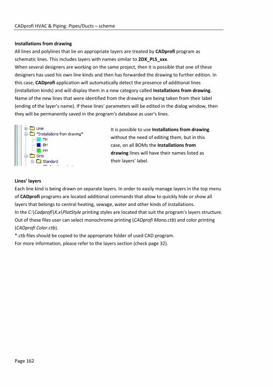
CADprofi HVAC & Piping: Pipes/Ducts – scheme
Page 162
Installations from drawing
All lines and polylines that lie on appropriate layers are treated by CADprofi program as
schematic lines. This includes layers with names similar to 2DX_PLS_xxx.
When several designers are working on the same project, then it is possible that one of these
designers has used his own line kinds and then has forwarded the drawing to further edition. In
this case, CADprofi application will automatically detect the presence of additional lines
(installation kinds) and will display them in a new category called Installations from drawing.
Name of the new lines that were identified from the drawing are being taken from their label
(ending of the layer's name). If these lines' parameters will be edited in the dialog window, then
they will be permanently saved in the program's database as user's lines.
It is possible to use Installations from drawing
without the need of editing them, but in this
case, on all BOMs the Installations from
drawing lines will have their names listed as
their layers' label.
Lines’ layers
Each line kind is being drawn on separate layers. In order to easily manage layers in the top menu
of CADprofi programs are located additional commands that allow to quickly hide or show all
layers that belongs to central heating, sewage, water and other kinds of installations.
In the C:\Cadprofi\X.x\PlotStyle printing styles are located that suit the program's layers structure.
Out of these files user can select monochrome printing (CADprofi Mono.ctb) and color printing
(CADprofi Color.ctb).
*.ctb files should be copied to the appropriate folder of used CAD program.
For more information, please refer to the layers section (check page 32).

CADprofi HVAC & Piping: Working with symbols – general rules
Page 163
Working with symbols – general rules CADprofi program possesses several commands used for inserting symbols into the drawing. It is
possible to insert symbols in any point, into lines, as well as the simultaneous insertion of multiple
symbols in the drawing.
CADprofi symbols have certain properties, thank to which they behave in a "smart" way, for
example automatically adjust the insertion angle to the line, automatically break the line at
insertion point, adjust the layer depending on the kind of installation etc.
All symbols available in CADprofi program are being inserted as blocks, which can be copied,
deleted or edited with the use of standard CAD program commands. Most symbols can be also
edited with the use of CADprofi editing commands such as: Quick edit, Edit symbols and Delete
symbols.
Symbols are often used to graphically represent real devices, armature and other installations
elements, therefore it is possible to add technical parameters, about the products used in the
project, to the symbols (Attributes and descriptions command), as well as numbering and
symbols' marks. This information can be used when describing drawings when creating graphical
legends or specifications (check page 46).
The following commands are used in order to insert symbols into the drawing: Multisymbols,
Symbols and Marks.
Each command that is used for working with symbols has got
a variety of options used insertion of single or multiple
symbols into the drawing.
Main options (available after pressing the button):
Insert symbol or symbols.
Into many lines.
In extension.
Into point.
‘Insert symbol’ option
This is the default option that allows to insert symbols in any point or into a line indicated by user.
Insert into a line Insert in any point

CADprofi HVAC & Piping: Working with symbols – general rules
Page 164
Procedures Insert symbol
1. Select the symbols or symbols in any library.
2. Click the Insert symbol button. The library dialog window will close allowing insertion
of symbols into the drawing.
3. Point into a line, in which you would like to insert the symbol.
4. (Optional) Click anywhere in the drawing to insert a symbol.
5. (Optional) Specify the rotation angle of inserted symbol - this option is available only if
user has selected the Rotate option in the library dialog window.
When inserting symbols into lines, the symbol insertion angle depends on the line angle (the
angle specified in the dialog box is being ignored).
In this case, if user selects the Rotate option then he will be able to specify symbol's rotation
relatively to the line. This option is very convenient when inserting symbols which have a
possibility to determine their tap direction, handle position, flow direction etc.
The angle of such symbol will be dependant on the position of P2 point.
Without rotation With rotation
‘Into point’ option
The Into point option may be used when it is necessary to insert the symbol in a point that lies on
a line, but in such a way that the symbol won't "adjust itself to the line". In this option, the
inserted symbol "ignores" the line, so it does not break it and it does not take angle from it. This
option is used in many situations for example when inserting sensors, which usually need to
touch lines.
Inserting symbol in a line point Inserting sensor in a line point

CADprofi HVAC & Piping: Working with symbols – general rules
Page 165
Procedures Insert into indicated point
1. Select the symbols or symbols in any library.
2. With the use of button, pull-down the insertion list.
3. Click the Into point button. The library dialog window will close allowing insertion of
symbols into the drawing.
4. Point into a point in a line, in which you would like to insert the symbol.
5. (Optional) Click anywhere in the drawing to insert a symbol.
6. (Optional) Specify the rotation angle of inserted symbol - this option is available only if
user has selected the Rotate option in the library dialog window.
‘In extension’ option
The In extension option allows to precisely specify the symbol insertion point in relation to other
objects located in the drawing. This allows to insert a symbol in a point in accordance with for
example another symbol.
Inserting in extension
Procedures Insert in extension
1. Select the symbols or symbols in any library.
2. With the use of button, pull-down the insertion list.
3. Click the In extension button. The library dialog window will close allowing insertion of
symbols into the drawing.
4. Click a line, in which you would like to insert the symbol (P1).
5. Specify the symbol insertion point against you would like to specify the location of the
inserted element (P2).
6. Specify an additional offset or click Enter to confirm the insertion point.
7. (Optional) Specify the rotation angle of inserted symbol - this option is available only if
user has selected the Rotate option in the library dialog window.
8. Symbol will be inserted in the drawing and the command will end (if user has not
selected the Insert multiple option).

CADprofi HVAC & Piping: Working with symbols – general rules
Page 166
‘Into many lines’ option
Into many lines option gives the possibility to quickly insert selected symbol into many lines. It
allows to insert selected symbol into all lines that cross with the „indication line”, that was
specified during insertion (P1–P2).
Inserting symbols into many lines
Procedures Insert into many lines
1. Select the symbols or symbols in any library.
2. With the use of button, pull-down the insertion list.
3. Click the Into many lines button. The library dialog window will close allowing insertion
of symbols into the drawing.
4. Specify the first point of the “crossing line” that will cross with lines (P1).
5. Specify the second point of the “crossing line” that will cross with lines (P2).
6. The selected symbol will be inserted in all lines that crossed with the “crossing line”.
Symbols in isometry
CADprofi allows to create axonometric drawings. CADprofi application performs an appropriate
transformation of inserted symbols in such a way that they are given an inclination that
corresponds with the current isometric angle.
After selecting the Isometry option, the meaning of rotation and mirror controls changes. The
default symbols insertion angle is the isometric angle that is defined in the CADprofi Options
(check page 31).
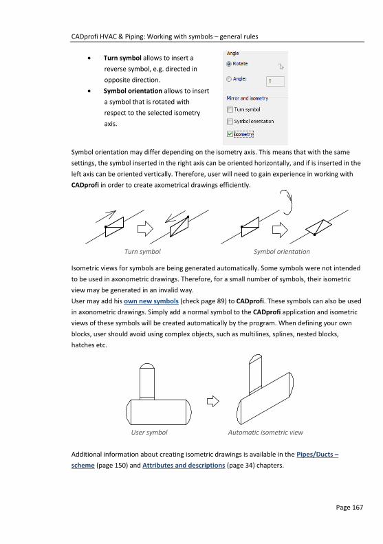
CADprofi HVAC & Piping: Working with symbols – general rules
Page 167
Turn symbol allows to insert a
reverse symbol, e.g. directed in
opposite direction.
Symbol orientation allows to insert
a symbol that is rotated with
respect to the selected isometry
axis.
Symbol orientation may differ depending on the isometry axis. This means that with the same
settings, the symbol inserted in the right axis can be oriented horizontally, and if is inserted in the
left axis can be oriented vertically. Therefore, user will need to gain experience in working with
CADprofi in order to create axometrical drawings efficiently.
Turn symbol Symbol orientation
Isometric views for symbols are being generated automatically. Some symbols were not intended
to be used in axonometric drawings. Therefore, for a small number of symbols, their isometric
view may be generated in an invalid way.
User may add his own new symbols (check page 89) to CADprofi. These symbols can also be used
in axonometric drawings. Simply add a normal symbol to the CADprofi application and isometric
views of these symbols will be created automatically by the program. When defining your own
blocks, user should avoid using complex objects, such as multilines, splines, nested blocks,
hatches etc.
User symbol Automatic isometric view
Additional information about creating isometric drawings is available in the Pipes/Ducts –
scheme (page 150) and Attributes and descriptions (page 34) chapters.

CADprofi HVAC & Piping: Working with symbols – general rules
Page 168
Usage of symbols inserted with a fixed angle
In order to maintain the project correctness, some symbols are being inserted with a fixed angle.
Examples include gravels and separators. These symbols should be inserted with a 0° angle.
In CADprofi many symbols have got an enforced insertion angle. When user will insert such
symbols in horizontal or vertical lines, these lines will automatically break. In other cases, lines are
not being broken.
Vertical line Horizontal line Incline line
Symbols that contain text (visible attributes)
For symbols that contain text (visible attributes) CADprofi program will automatically adjust angle
of the text. Thanks to this the situation in which text would be displayed "upside down" or
"backwards" is being avoided. User has the following possibilities to adjust texts:
0° fixed angle.
0° or 90° angle. If symbol is inserted with a 90° angle, then the text is also rotated by
90°. In other cases the text angle is 0°.
Automatic angle from -30° to +120°. In these ranges the text rotation angle is
sufficiently readable.
Adjustment of attributes angle
Notice
For symbols with a fixed insertion angle, "Angle" and "Rotation" options located in the dialog box are being ignored.

CADprofi HVAC & Piping: Working with symbols – general rules
Page 169
Notice
Options for text adjusting are permanently set for each symbol.
User can change these options only for symbols that were added by
the user.
Smart copying of symbols
In order to accelerate the work, CADprofi program allows for smart copying of symbols from the
current drawing.
The Pick symbol option is available in the Multisymbols and Ventilation - Multisymbols. After
selecting this option, program will hide the dialog window and enable selection of symbols that
will be copied (e.g. P1, P2, P3). Symbols will be copied in the same order that they were selected
in the drawing. It is possible to select a single symbol repeatedly. After the selection of symbols is
done, press the Enter key (or right mouse button). The dialog window will be displayed again, in
which user will be able to freely specify all options (check page 179) related to insertion of copied
symbols. The process of inserting these symbols is the same as for the symbols selected from
CADprofi libraries (e.g. inserting into a point or in a line – P4, P5)
Copying of three symbols with inserting them in a line
Notice
If during the symbol selection, user will select an object, which is not compatible with the command, then it won't be added to the list of copied symbols. It is also unacceptable to simultaneously
copy symbols from different modules such as for example electrical
and piping symbols.

CADprofi HVAC & Piping: Working with symbols – general rules
Page 170
Find symbols
In each dialog window that is used for symbols insertion there is a search option, thanks to which
it is possible to quickly find desired symbols.
The Find field is used to enter a phrase (full or just a part
name of searched symbol). This field remembers typed
words, which allow user to search again from the
expanded list by pressing the button and clicking Find.
After filling the search field, application will automatically filter the current library content and
display only those categories which contain the objects that match the search results. Clicking the
Restore button will display all library objects and end the search.

CADprofi HVAC & Piping: Working with symbols – general rules
Page 171
Multivariant symbols
Multivariant symbols are objects, thanks to which in a quick and easy way user can customize
their view or information contained in the inserted object. In this way, one multivariant symbol
can replace many "traditional" ones, while giving a better possibility to configure their look and
type.
Multivariant symbols may be freely modified, using the Edit symbols command.
Example of a multivariant symbol
Angular valve – the symbol options allow user to specify:
type of valve,
type of propulsion,
type of connection regardless of both endings.

CADprofi HVAC & Piping: Working with symbols – general rules
Page 172
Management of symbols content
CADprofi program possesses several thousands of symbols grouped in appropriate categories.
Witch such a large number it is sometimes hard to find symbols needed at the moment. On the
other hand, when working on a particular project it is usually not needed to work with more than
several dozens of symbols. In order to speed the work, user can add selected items to the
*Favourites* category thanks to which he will be able to get a much faster access to them.
It is possible to create sub-categories related to a specific theme, such as a separate category for
symbols used in designing boilers, sanitary installations and more. Furthermore, one element can
be added to many sub-categories.
For elements placed in the *Favourites* category it is possible to change their name, which will
be later used in BOMs, legends and descriptions. Change of name can be also used to user own
translations for some symbols from international standards.
Adding symbols to favourites
Add to favourites button allows to copy any symbol to the *Favourites* category. This folder
is created automatically after user has copied the first symbol.
Changing the symbol name
Initially, each copied symbol receives the
default name from the original item.
In order to change the symbol name that
is located in the *Favourites* folder,
user should first select it and then press
the F2 button to activate the edition
mode.
Changing category
In order to change or define a new
category, click the right mouse button on a
desired symbol and from the context menu
choose the Change category option.
Notice
Changed name will be visible in tables and descriptions that are
created with the „Bill of materials” (check page 46) command.

CADprofi HVAC & Piping: Working with symbols – general rules
Page 173
In the dialog box, user can select an existing
category or enter a new category name.
After accepting, selected symbol will be
moved to the defined category.
CADprofi application allows to create many
copies of each symbol and it is possible to
place them in different categories. Thanks
to this user can create categories that
group symbols of a specified type or the
most common used symbols for a given
industry type.
Changing the category or many symbols
If user is editing a symbol in his native
category in which there are many symbols,
then CADprofi application will change
category for all these symbols.
Deleting symbols
It is possible to delete symbols from the *Favourites* category. To do so, select the symbol and
choose the Delete option from the dialog window.

CADprofi HVAC & Piping: Symbols
Page 174
Symbols Both Symbols and Ventilation - Symbols commands allow to insert various symbols from the
available library.
When inserting symbols into a line, application will automatically break the line in the insertion
point, while maintaining the rules of creating schematic drawings.
Symbols dialog window
The Symbols dialog window contains the following elements:
Tools menu:
Define new – allows to add a new element to the database. Read more about it in
the Defining user blocks (check page 89).
Edit – allows to Editing user block parameters (check page 92).
Add to favourites – copies symbol to the *Favourites* (check page 172) category.
Delete – deletes the selected symbols from the *Favourites* category.
Pop-up menu– options menu for the selected symbol,
which is available after right clicking on the
mouse button on the selected symbol.
Commands in this menu are similar to the tools
menu.

CADprofi HVAC & Piping: Symbols
Page 175
Categories tree – a set of all categories and symbols in the library, shown as a pull-down tree.
User can customize the display order by using the following options:
Sort – alphabetical order of categories placement and their content.
Show norms– enables/disables displaying symbols according to norms.
Thumbnail view – displays the content of currently selected category as thumbnails.
Preview – displays the preview of the currently selected symbol. Right-clicking on the preview
window will zoom the view.
Angle/Rotation – possibility to specify a fixed angle when inserting symbols or enabling the
rotation option, in which symbol's angle is defined by rotation during insertion.
During insertion of symbols into lines, the insertion angle depends on the line angle
(the angle specified in the dialog window is being ignored).
When inserting symbols into lines it is possible to use the Rotation option in order to
dynamically specify symbol rotation relatively with the line. This option is very
convenient when inserting symbols of pumps, vales etc.
0° angle Rotation
30° angle Inserting into a line
Scale – specifies the size of inserted symbols. It is possible to enter the scale value or to
indicate a symbol on the drawing whose scale user would like to use.
System – if in the program options, the extended layer name structure (check page. 29) is
enabled then symbols will be inserted on layers depending on the kind of installation
(system). In case of inserting symbols into an existing line then the System option is
being ignored and the symbol layers depends on the line kind.
Mirror and isometry:
Mirror X, Y– enabling this option will create an X or Y mirror image for the specified
object.
Isometry – enabling this option will convert the symbol, so it will possible to use it in
isometrical schemes.

CADprofi HVAC & Piping: Symbols
Page 176
This option may not be available for some symbols.
Object data– this option allows to specify symbols technical or identification parameters. For
each symbol, different parameters can be given such as: Article, Manufacturer,
Reference (Catalog number), DN, PN and others. In order to fill the parameters enter
any text or choose a value from the available list.
Remember data– this option allows to save the user entered parameters. This option should be
enabled when user inserts symbols with similar characteristics.
Insert multiple– enables/disables the possibility of inserting multiple symbols to the drawing. The
insertion process requires from the user to press the Enter or Esc key when he finished
inserting multiple symbols.
Procedures Inserting symbol
1. Run the Symbols or Ventilation – Symbols command.
2. In the dialog window choose the appropriate category.
3. Select the symbols that you would like to insert. In the bottom-left corner of the dialog
window a preview of the selected symbol will be displayed.
4. Specify the insertion parameters: System, Rotation, Scale.
5. (Optional) In accordance with your preferences fill out the value of following
parameters: Article, Manufacturer, Reference, DN, PN.
6. Click the Insert symbol button in order to specify the symbol insertion point.
7. (Optional) With the use of the button pull-down the insertion list and choose In
extension to specify the insertion point in accordance to other objects.
8. (Optional) With the use of the button pull-down the insertion list and choose Into
point to insert the symbol in a specific point.
9. (Optional) With the use of the button pull-down the insertion list and choose Into
many lines to insert symbols simultaneously into many lines.
10. Click on a point in the line to insert the symbol.
11. (Optional) Click on any point in the drawing, to insert the symbol without inserting it
on a line.
12. (Optional) Specify the inserted symbol angle - this option is available only if the
Rotation option in the library dialog window has been enabled.
13. After closing the dialog box, insert the symbol into the drawing.
Symbols

CADprofi HVAC & Piping: Cross symbols
Page 177
Cross symbols The Cross symbols command is used for automatic insertion of angular, three-way or four-way
symbols in line crossings.
The default cross symbol insertion process involves indicating two lines. After that program
automatically inserts a symbol in the intersection. Indicated lines can be interrupted or properly
extended.
Inserting a cross symbol
The basic functionality and symbols options are being described in the Symbols (check page 174)
chapter.
Procedures Inserting a cross symbol into a line crossing
1. Run the Cross symbols command.
2. In the dialog window choose the appropriate category.
3. Select the symbols that you would like to insert in the drawing.
4. Check the scale and symbols parameters.
5. (Optional) In accordance with your preferences fill out the value of following
parameters: Article, Manufacturer, Reference, DN, PN.
6. Click the Insert symbol button in order to indicate lines in which you would like to
insert selected symbol.
7. Indicate the first line in the drawing in which the symbol should be inserted (main line
P1).
8. Indicate the second line in the drawing (P2).
9. Symbol will be inserted in the drawing, lines will be properly interrupted or extended
or shortened.
Cross symbols

CADprofi HVAC & Piping: Cross symbols
Page 178
When inserting three-way symbols the first point (P1 or P1’) defines the main line, while the next
point (P2) defines a secondary line. In case of an angular valve choosing the point (P1 or P1’)
defines the direction in which the valve is being inserted.
Inserting cross symbols
A second possibility of inserting a cross symbol is to indicate the actual line crossing of two lines
(P1) and afterwards indicate the (P2) point, which specifies the symbol rotation. CADprofi
application will automatically detect and interrupt the connected lines.
Inserting a cross symbol
Notice
Automatic adjustment and lines interruption takes place if indicated lines intersect with each other at a right angle.
Inserting a symbol at the line crossing is possible only for the "Insert symbol" option (other options, such as "Into many lines" will insert a symbol accordingly to the description in the „Symbols”.
command).
Inserting a symbol at the line crossing won't be possible if one of
these lines is a polyline.

CADprofi HVAC & Piping: Multisymbols
Page 179
Multisymbols Multisymbols and Ventilation – Multisymbols commands allow simultaneous insertion of many
symbols in one row. These symbols may be inserted either in an existing line or in a chosen point.
Symbols are being grouped in categories according to their standards or according to their
element types.
Multisymbols dialog window
The Multisymbols dialog window contains the following items:
Symbols categories and libraries – display a list of library categories and their content. In order to
change the category user should expand the list using the button, and then click on
the selected item. After that the content of this category will be displayed as
thumbnails. Click on a chosen symbol in order to add it to the list of symbols to insert.
Symbols to insert – this window contains a list of symbols, which will be inserted into the
drawing, preserving their order. Their order can be changed using the move up ,
move down buttons and the drag and drop method. Other options:
Delete – deletes the selected symbol from the list.
Copy – copies the selected symbol that’s located on the list.
Pick symbol – selects a symbols from the drawing and inserts it on the list.
Most recently selected symbols – adds to the “Symbols to insert list”, elements
from the previously performed Multisymbols command.

CADprofi HVAC & Piping: Multisymbols
Page 180
Find – opens the find symbols dialog window.
System – in case of selecting one or more symbols into the drawing a row will be inserted with
all the selected symbols. In this row user can also add a line that is specified in the
System field (e.g. supply, water etc.).
If in the program options, the extended layer name structure (check page. 29) is
enabled then symbols will be inserted on layers depending on the kind of installation
(system).
Distance between symbols – specifies the distance between the symbols that are being inserted
in a single command. This distance can be measured between two extreme points or
between base points of each symbol. Space between the symbols will be filled with a
user selected line (System option).
Distance between symbols “0” distance between symbols
Distance between base point “0” distance between symbols
Scale – specifies the size of inserted symbols. It is possible to enter the scale value or to
indicate a symbol on the drawing whose scale user would like to use.
Notice
List of inserted symbols can contain a maximum of 20 positions that can be inserted in one command.
Hint
If distance value is set as „0”, then symbols will be drawn directly
one after the other.

CADprofi HVAC & Piping: Multisymbols
Page 181
Procedures Pick symbol with appropriate scale.
1. In the library window click the Pick symbol with appropriate scale button.
2. Library window will close, allowing user to indicate a symbol in the drawing.
3. After indicating the symbol the dialog window will appear again and the scale value
will be set in accordance with the scale of the indicated symbol.
Angle/Rotation – possibility to specify a fixed angle when inserting symbols or enabling the
rotation option, in which symbol's angle is defined by rotation during insertion.
During insertion of symbols into lines, the insertion angle depends on the line angle
(the angle specified in the dialog window is being ignored).
When inserting symbols into lines it is possible to use the Rotation option in order to
dynamically specify symbol rotation relatively with the line. This option is very
convenient when inserting symbols of pumps, vales etc.
Inserting into a line with rotation
Insert symbol –the default option that allows to insert symbols in any point or into a line
indicated by user. When inserting symbol into lines, the lines are being automatically
interrupted in appropriate points.
Hint
In CADprofi it is recommended to use an appropriate scale in
accordance with the currently used drawing units. For designing in mm the default scale is 200, for cm 20 and for m is 0.2.
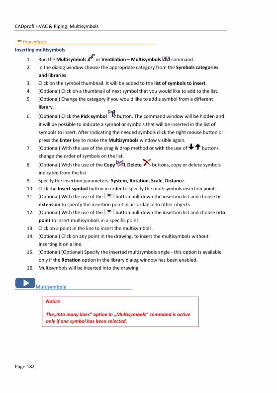
CADprofi HVAC & Piping: Multisymbols
Page 182
Procedures Inserting multisymbols
1. Run the Multisymbols or Ventilation – Multisymbols command.
2. In the dialog window choose the appropriate category from the Symbols categories
and libraries.
3. Click on the symbol thumbnail. It will be added to the list of symbols to insert.
4. (Optional) Click on a thumbnail of next symbol that you would like to add to the list.
5. (Optional) Change the category if you would like to add a symbol from a different
library.
6. (Optional) Click the Pick symbol button. The command window will be hidden and
it will be possible to indicate a symbol or symbols that will be inserted in the list of
symbols to insert. After indicating the needed symbols click the right mouse button or
press the Enter key to make the Multisymbols window visible again.
7. (Optional) With the use of the drag & drop method or with the use of buttons
change the order of symbols on the list.
8. (Optional) With the use of the Copy , Delete buttons, copy or delete symbols
indicated from the list.
9. Specify the insertion parameters: System, Rotation, Scale, Distance.
10. Click the Insert symbol button in order to specify the multisymbols insertion point.
11. (Optional) With the use of the button pull-down the insertion list and choose In
extension to specify the insertion point in accordance to other objects.
12. (Optional) With the use of the button pull-down the insertion list and choose Into
point to insert multisymbols in a specific point.
13. Click on a point in the line to insert the multisymbols.
14. (Optional) Click on any point in the drawing, to insert the multisymbols without
inserting it on a line.
15. (Optional) (Optional) Specify the inserted multisymbols angle - this option is available
only if the Rotation option in the library dialog window has been enabled.
16. Multisymbols will be inserted into the drawing.
Multisymbole
Notice
The„Into many lines” option in „Multisymbols” command is active
only if one symbol has been selected.

CADprofi HVAC & Piping: Schemes
Page 183
Schemes The Schemes command allows to insert already prepared schemes or typical schemes fragments
such as containers connection systems, various valves systems, heating circuits, typical boiler
schemes, heating schemes, etc.
When inserting, scheme is often broken into it parts. Thanks to it is possible to edit the drawing,
add descriptions etc.
Schemes dialog window
The Schemes dialog window contains the following items:
Tools menu:
Define new – allows to add a new element to the database. Read more about it in
the Defining user blocks (check page 89).
Edit – allows to change selected user block.
Add to favourites – copies symbol to the *Favourites* (check page 172) category.
Delete – deletes the selected symbols from the *Favourites* category.
Pop-up menu– options menu for the selected symbol,
which is available after right clicking on the
mouse button on the selected symbol.
Commands in this menu are similar to the tools
menu.

CADprofi HVAC & Piping: Schemes
Page 184
Angle/Rotation – possibility to specify a fixed angle when inserting symbols or enabling the
rotation option, in which symbol's angle is defined by rotation during insertion.
Scale – specifies the size of inserted symbols. It is possible to enter the scale value or to
indicate a symbol on the drawing whose scale user would like to use.
Schemes
Example of a scheme from the manufacturer’s libraries:
In order to insert schemes from the manufacturers libraries run the Manufacturers library
command from the main CADprofi toolbar or from the upper menu. Afterwards select the library
of required manufacturer. In the program there are many already prepared boiler schemes
prepared accordingly to ACV, Viessmann and Vaillant catalogs.
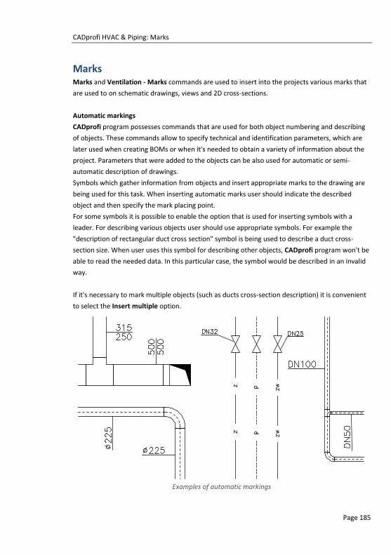
CADprofi HVAC & Piping: Marks
Page 185
Marks Marks and Ventilation - Marks commands are used to insert into the projects various marks that
are used to on schematic drawings, views and 2D cross-sections.
Automatic markings
CADprofi program possesses commands that are used for both object numbering and describing
of objects. These commands allow to specify technical and identification parameters, which are
later used when creating BOMs or when it's needed to obtain a variety of information about the
project. Parameters that were added to the objects can be also used for automatic or semi-
automatic description of drawings.
Symbols which gather information from objects and insert appropriate marks to the drawing are
being used for this task. When inserting automatic marks user should indicate the described
object and then specify the mark placing point.
For some symbols it is possible to enable the option that is used for inserting symbols with a
leader. For describing various objects user should use appropriate symbols. For example the
"description of rectangular duct cross section" symbol is being used to describe a duct cross-
section size. When user uses this symbol for describing other objects, CADprofi program won't be
able to read the needed data. In this particular case, the symbol would be described in an invalid
way.
If it's necessary to mark multiple objects (such as ducts cross-section description) it is convenient
to select the Insert multiple option.
Examples of automatic markings

CADprofi HVAC & Piping: Marks
Page 186
Marks dialog window
General functionality as well as symbols options were described in the Symbols (check page. 174)
chapter. Additional options that are available in the Marks dialog window:
Leader – enables/disables usage of leader for descriptions. By clicking on the button, that
symbolizes the currently set arrow type, user can change the following leader settings:
Arrow type– symbol that is inserted in the leader starting point for example an arrow.
Arrow size – determines the leader scale.
Insert single segment –drawing of a one or multi-segment leader.
Text height – specifies the marks text height and scale. User can enter a value or indicate it from
the drawing (indicate two points).

CADprofi HVAC & Piping: Marks
Page 187
Precision of dimensions – defines the precision (decimal number) of all values of dimensions that
are placed in marks. These dimensions are automatically retrieved from the indicated
object.
Background mask – enables/disables the possibility to mask the symbol background by adding a
WIPEOUT. This feature is helpful if user needs to highlight important information in the
drawing.
Procedures Inserting an automatic description (multivariant symbol)
1. Run the Marks or Ventilation – Marks command.
2. In the Marks dialog window select Marks category from the list of available categories.
In the top-right corner the category content will be displayed as thumbnails.
3. Click on a thumbnail of a chosen symbol, in the bottom-left corner you will be able to
see the symbol preview.
4. (Optional) Change the data type by clicking the Browse button to select the data
from the list of available data in the Select dialog window.
5. Specify the parameters: Angle, Mirror, Isometry and Scale.
6. (Optional) Enable and change Leader settings.
7. Enable/disable the background mask.
8. Enable/disable the Insert multiple option.
9. Click the Insert symbol button, to insert the desired mark into the drawing.
10. Indicate the symbol/object whose data should be inserted into the drawing.
11. Indicate the mark insertion point.
12. (Optional) If the Insert single segment option (in the leader settings) is turned on then
indicate a series of points that are segments ends or click the right mouse button to
continue.
13. (Optional) Specify the mark rotation angle.
14. Mark will be inserted in accordance to the selected settings.
15. (Optional) If in the dialog window the Insert multiple option is enabled then repeat the
steps 10-13 in order to insert an additional mark or end the command by clicking the
Esc key.
Marks
To edit marks user can use CADprofi commands such as Edit symbols, Attributes and
descriptions (check page 34) or CAD program commands such as Edit attributes - _DDATTE.

CADprofi HVAC & Piping: Marks
Page 188
Multivariant marks and object numbering
Many mark symbols are multivariant symbols, for which user has got a possibility to customize
the appearance and to select additional options. For these symbols in the dialog window there
are selection fields and text fields buttons available that allow to specify the variant or adoption
of symbol to current needs.
An example of such multivariant symbol is the "Objects numeration" symbol. This symbol can
number objects and also retrieve from them required parameters (e.g. name, type etc.). In this
way it is possible to quickly number many objects and insert required text in the drawing.
CADprofi program automatically detects
numbered objects in the drawing, thanks to
which in the dialog window the first
available number from the specific branch
(e.g. HS - heating and sanitary installations)
is being displayed. The button allows
to select the next highest number.
By adding different number prefixes, user can create many numbered sequences (e.g. one Z1, Z2,
Z3 sequence for valves and one P1, P2, P3 for pumps).
Inserting symbols with the Insert mupltiple option will cause the symbols to have numbers added
to them with increased numeration (e.g. from 1 to 10).
The Mark 1, Mark 2 fields allow to add in the selected symbol any text or information retrieved
from the indicated object. Selecting the information type will be possible after pressing the
button that is located next to the field.
In the newly opened window user can select
the following information:
Attributes – indicated object
attributes values.
Lines – line type or installation
kind.
Dimensions – dimensions
retrieved from the indicated
object.
Others – for example the CAD
program system variable values.

CADprofi HVAC & Piping: Plumbing objects – scheme
Page 189
Plumbing objects – scheme Special kind of symbols are plumping objects that are used in plumbing strand diagrams.
In strand diagram drawings it is necessary to maintain the vertical scale on the printouts.
Therefore, the sanitary symbols are being inserted in standard size. This size depends on the used
design unit (mm, cm, m) that's why the scale change option is blocked.
Plumbing objects can be inserted next to the risers from the right or left side. For some symbols it
is necessary to turn on the Mirror X option. Symbols of plumbing objects should be inserted with
"0" angle.
Plumbing objects – scheme dialog window
The basic functionality and symbols options are being described in the Symbols (check page 174)
chapter.

CADprofi HVAC & Piping: Plumbing objects – scheme
Page 190
Procedures Inserting symbol
1. Run the Plumbing ojects - scheme command.
2. In the Plumbing ojects - scheme dialog window select the needed symbol from the
appropriate category.
3. Click the thumbnail of the symbol that you would like to insert into the drawing. In the
down-left corner you may see the preview of selected symbol.
4. Select the appropriate system.
5. (Optional) Enable the Mirror X option.
6. Click the Insert symbol button, to specify the object insertion point (P1).
7. Symbol will be inserted into the drawing.
Plumbing objects – scheme
Notice
For all plumbing objects the insertion point is defined at the floor level. For this reason, before placing the first symbol user should
draw a ceiling cross-section.
During inserting plumbing objects symbols on strand diagrams user
should always indicate the point that lies upper floor edge (P1).

CADprofi HVAC & Piping: 2D views of piping and ventilation installations
Page 191
2D views of piping and ventilation installations Creating drawings of 2D installations is related to drawing lines, adding objects and descriptions.
CADprofi program enables automatic drawing of line strings and fittings of any kind in 2D view. It
also allows user to quickly connect lines and to edit them. It is also possible to insert armature
views in previously drawn lines with an ability to automatically insert reduction. All objects are
inserted on appropriate layers that define their line kinds or system (supply, return, air etc.).
An example of 2D view
CADprofi program possesses different objects:
Radiators – it is possible to use radiators on 2D projections and strand diagrams.
Plumbing objects– objects used in designing water and sewage installations.
Parametrical objects– these objects represent actual views of devices such as boilers,
tanks, block pumps etc. For parametrical objects it is possible to specify their technical
data and all dimensions.
Parametrical armature just like with the objects, parametrical armature represents
actual devices view (armature, lines equipment, flanges, in-line 2D lines). The main
feature of these objects is the ability to insert them in 2D lines.
Objects from manufacturer’s libraries – they are available in the Products library
command. Products libraries are created together with manufacturers and therefore
contain a very comprehensive source of objects (blocks) that are used in designing.
Products libraries are constantly being updated and are made available by
manufacturers on the internet. After installing CADprofi program it is possible to
install additional libraries at a later time that will be added to the program.
Objects defined by users – every user can add to the program any objects used in
designing.
CADprofi HVAC & Piping: 2D lines and fittings
Page 192
2D lines and fittings In CADprofi program it is possible to create 2D views and cross-sections of pipes and ducts. When
drawing installations lines and fittings (elbows, reducers, tee-pieces) are available. Each fitting is a
parametrical object, which is being drawn with appropriate program procedures. Thank to this it
is possible to draw fittings with specified dimensions. For pipes and fittings databases are
available that contain definitions of standardized elements of chosen manufacturers.
Lines and fittings are available in the following commands:
2D Pipes - plan – this command contains typical pipes and fittings used in designing piping
installations.
2D Ducts – this command contains ducts and fittings of circular and rectangular shape used
in designing ventilation and air conditioning installations.
2D Pipes/Ducts sequence – this command allows to draw many lines segments with
automatic insertion of elbows.
Steel/copper/plastic/sewage piping systems – this command contains specific types of
lines and fittings, as well as, allows user to to draw many sections of lines with automatic
insertion of elbows.
2D Join pipes/ducts – this command is used for a convenient connecting of lines with an
automatic insertion of an appropriate fittings.
In all these command, a similar dialog window is being used. This dialog window has got a list that
is used to define parameters for fittings. A set of available parameters depends on the type of
selected fitting. The meaning of each individual parameter is similar for many fittings, that's why
we ask users to read carefully all the explanations explained in this chapter so it will be possible to
fully exploit the program opportunities.
Inserting lines and fittings
Both 2D Pipes - plan and 2D Ducts commands allow to insert single fittings or lines to the
drawing.
After running the command it is possible to select the needed fitting or line and to specify the
dimensions and insertion options. CADprofi program also possesses features that automate
connecting elements to each other. It is also possible to automatically adjust the line size and the
system kind when connecting lines to other elements. The below examples were created with
using these functions.

CADprofi HVAC & Piping: 2D lines and fittings
Page 193
Methods of automatic connections of lines, connectors and fittings:
Automatic connection of a fitting to an installation element
1. Indicate an element to which you
would like to connect a fitting
(P1).
2. Specify the fitting insertion
direction (P2).
Inserting a tee-piece with the „Insert in line” option
1. Indicate in line in which you
would like to insert a tee-piece
(P1).
2. Specify the fitting insertion point
(P2).
3. Specify the tee-piece direction
(ramification) (P3).
Inserting a coupling into an existing line
1. Specify the insertion point (P1).
2. Automatic adjustment of the
angle that was specified in the
dialog window (alfa).
Inserting a line with the „Join object” option enabled
1. Indicate an object to which you would like to connect a line (P1).
2. Specify the new line length (P2).
When connecting pipes or ducts to other installation elements, both Diameter fit and Width and
height fit options are useful. Thanks to them the inserted line will always have the same size as
the indicated object.

CADprofi HVAC & Piping: 2D lines and fittings
Page 194
Z+/Z– lines and fittings
Z+/Z- lines show vertical line segments (along the Z axis). For these lines on projections only the
appropriate cross-section symbol is visible. For this reason, the Z+/Z- line length should be
specified in the dialog window before inserting lines to the drawing.
For Z+/Z- lines and fittings it is possible to additionally specify the symbol cross-section (Z+, Z- or
without symbol) and the insertion point (beginning, axis, end).
Z+ Z– Without symbol
Copying fittings dimensions
During drawing it is often necessary to insert elements similar to other elements that are already
inserted in the drawing. In this case, it is convenient to copy dimensions from other fittings. After
pressing the Copy dimensions button, user should indicate a desired fitting. It is important to
avoid identifying fittings that have completely different parameters than the currently selected
element in the dialog window. In such cases, user may experience an ambiguity in the data
interpretation.
For example: if in the dialog window user has selected an elbow, and when copying dimensions
user will indicate a reducer, then CADprofi won't be able to determine the curvature radius and
the elbow angle, because reducer doesn't posses such parameters.

CADprofi HVAC & Piping: 2D lines and fittings
Page 195
Defining user own fittings
When designing installations it is sometimes needed
to use non-standard fittings. In this case, user can
define his own fittings, which will be taken into
account during numbering or during creating BOM.
In order to define a new additional fitting, user should
draw it first and then run the 2D Pipes - plan or the
2D Ducts command. After that user should choose
the User object defining option.
For the newly created fitting user should choose a
name. Optionally user can also specify the
manufacturer, type and product parameters.
After clicking the OK button, user should select
objects from the list that the new fitting is being
made up from and to choose the base point.
If a fitting is often used then it is possible to add it to
the program library by using the User block wizard
(check page 87).
An example of defining a tee-piece (ramification).
Defined fitting consists of a rectangular segment and an arch. In order to draw a new fitting it is
convenient to use the 2D Ducts command, thanks to which it is possible to insert a rectangular
duct and a right arc with a 90° angle.
In order to use a new fitting in installations while maintaining colors and other characteristics all
elements should be moved to the "0" layer. It is necessary to have the fitting color the same as
the installation color (e.g. air, exhaust air). After that user should run the 2D Ducts command and
select the User object defining option. In the Name field enter a name for example "rectangular
tee".
After pressing the OK button, select the
elements that belong to the defined
fitting (P1–P2) and specify the fitting base
point (P3).
When the fitting is being defined it is also
automatically inserted on a layer that
belongs to the selected installation.

CADprofi HVAC & Piping: 2D lines and fittings
Page 196
2D Piping – plan/2D Ducts dialog window
2D Piping – plan/2D Ducts contains the following items:
Categories tree – a list of all available elements divided into categories.
Preview – displays the preview of the currently selected element. Right-clicking on the preview
window will zoom the view.
Sort – enables/disables alphabetical order of categories placement and their content.
Fixed dimensions – enables/disables the preserve of a basic dimension after inserting objects
such reducers. After inserting such element in which the line dimension is being
reduced in the next time user runs the command the application will automatically
change the default diameter into a reduced diameter (D2). This process is very
convenient when designing an installation sequence. However, if user wants to insert a
fitting that has an unchanged main cross-section then enabling the Fixed dimensions
option will prevent an automatic change of cross-section.

CADprofi HVAC & Piping: 2D lines and fittings
Page 197
Installation and how to draw:
Installation – possibility to choose the installation kind or define a new one. Initially on
the drop-down list only the most important CADprofi systems will be included.
However, user has the possibility to develop the list with his own elements (by using
the Add to most recently used option) in the Edit line data (check page 160). dialog
window. Selecting the Others/Edit option will open a new dialog window with full list
of available systems.
Define new – allows to add a
new position (line) to the list as a
user line. Afterwards it opens a
new edit window and allows user
to edit the line data.
Copy – copies the selected
line with all its parameters,
therefore creating an element
made by user.
Edit – opens the edit
properties window of user
created lines.
Delete – deletes the selected
line from the list.
List of available lines (installations) is similar to the list of lines available in the
Pipes/Ducts – scheme (check page 150) commands. Any changes made in one of these
commands will also appear in others.
Type – possibility to specify the fitting type (normal element, segment etc.).
Elbow types available in the program

CADprofi HVAC & Piping: 2D lines and fittings
Page 198
Manufacturer and type – selection of items from manufacturers standards or
databases. CADprofi program allows to draw fittings and 2D lines, whose dimensions
can be specified in two ways:
1. Drawing based on dimensions specified by user.
To enable this mode, in the Manufacturer field select „– –”.
2. Drawing based on manufacturers’ standards or databases. In order to activate
this mode select the required manufacturer (or standard). After selecting the
manufacturer it is not possible to
enter you own dimensions (this
option is blocked).
After selecting a specific manufacturer or standard a dialog window will appear
with available fittings or lines.
Element selection dialog window
Dimensions – In CADprofi program it is possible to draw fittings with any dimensions.
To do this, in the Manufacturer field select „– –"
When drawing is based on user selected dimensions then two field in which user can
enter values are available. button allows to select typical values, for example
standardized piping diameters or ducts cross-sections. The straight lines length is
determined in the drawing by indicating two points.

CADprofi HVAC & Piping: 2D lines and fittings
Page 199
Options – additional options that automates the drawing process:
Join object – automatic connection of inserted element to existing objects (line,
fittings or armature). When connecting, CADprofi program will automatically
determine the rotation angle and the element insertion point.
Installation fit – automatic determination of installation kind based on object, to which
the inserted element is being connected. Installation kind set in the dialog window is
being ignored.
Diameter fit – automatic identification of installation diameter based on object to
which a line is being connected. In the connection point it is possible to insert a
reducer or to ignore the line diameter from the dialog window.
Insert in a sequence – gives the possibility to insert fittings into an existing line or into
their extension. If this option is disabled then fittings are inserted on the end of the
line.
Thickness of insulation – determines the insulation thickness of inserted fitting or line. The
default value 0 disables insulation.
Description – enables/disables the display of description of the currently selected option
in the dialog window.
Copy dimensions – copies dimensions from a line/fitting indicated in the drawing.
OK – closes the window and allows to insert an element to the drawing.
Procedures Inserting lines
1. Run the 2D Pipes - plan or 2D Ducts command.
2. In the 2D Pipes - plan/2D Ducts from the list of available categories select the Pipe
from the Piping/heating category or Pipe flex from the Pipe flex category.
3. From the list of installations select the needed kind of installation in order to specify
the color and layer for a new line.
4. (Optional) Specify the values for the Manufacturer and type items.
5. In the Dimensions field specify the Diameter value for the selected line.
6. (Optional) Click the Copy dimensions button and indicate a line on the drawing from
which you would like to copy the diameter value.
7. (Optional) Enable/disable the Installation fit, Diameter fit, and Join object.
8. (Optional) Specify the Thickness of insulation.
9. Click the OK button to start drawing a line.
2D lines and fittings

CADprofi HVAC & Piping: Drawing line sequences
Page 200
Drawing line sequences The 2D Pipes - sequence and 2D Ducts - sequence commands allow to create piping sequences
with automatic insertion of elbows that have parameters defined by user. These commands have
the ability to disable the display of the dialog box, allowing user to immediately start drawing
lines sequences with the last used settings or with settings that matches the objects to which they
will be attached (with the Installation fit and Diameter fit options enabled).
2D Pipes – sequence/2D Ducts – sequence dialog window
Graphical layout and basic functionality of the dialog window is similar to the 2D Piping – plan/2D
Ducts (check page 196). Additional options available in this command:
Elbow parameters – a group of options that allow to specify parameters of elbows drawn in 2D.
Radius – allows user to determine the radius or radius ratio for elbows inserted
between each line segments.

CADprofi HVAC & Piping: Drawing line sequences
Page 201
Radius as a multiplier of width – enables/disables the possibility to determine the
radius through the width multiplier.
Type – allows user to choose the elbow type that will be used in the line sequence.
Limit max angle to 90° – enables/disables the possibility to reduce the line sequence
elbow angle to 90°.
Dimension E/Dimension F – allows to specify both E and F dimensions (that are visible on the
preview). button allows to specify the dimension by indicating two objects on the
drawing.
Reference edge – right or left edge. Edge is indicated accordingly to the drawing direction.
Procedures Inserting lines
1. Run the 2D Pipes - sequence or 2D Ducts - sequence .
2. (Optional) If the dialog window didn’t appear then start drawing or select the Settings
(S key) option, to change the settings.
3. In the dialog window choose the needed kind of line.
4. Choose installation kind.
5. (Optional) Specify the values for Manufacturer and type controls.
6. Specify the line Diameter (or cross-section).
7. (Optional) Enable/disable the Installation fit, Diameter fit, and Join object functions.
8. (Optional) Specify the Thickness of insulation.
9. Click the OK button to start drawing a line sequence by indicating the points.
Drawing line sequences
Hint
If the „Always show dialog box” option was disabled then if user
wants to enable it again he has to choose Settings (abbreviation „S” in the command line) after running the command.
Drawing direction
Left edge
Right edge

CADprofi HVAC & Piping: Drawing line sequences
Page 202
How to draw
When drawing users should indicate points (P1, P2 etc.). If you draw by the axis and without an
offset line segments are being inserted along with the indicated points.
Pipe Pipe flex
Rectangular pipes with elbows Rectangular pipes with arches
When drawing with an offset the line sequence is being drawn with a specified distance from the
indicated points.
An example of drawing lines accordingly to the edge and with an offset:
After drawing lines, they
were later connected with a
tee-piece using the 2D Join
pipes/ducts command
(points P7 and P8).
Drawing
direction
(P5 – P6)
Drawing
direction
(P1 – P4)
Edge: Right
Offset: 300
Edge: Left
Offset: 300

CADprofi HVAC & Piping: Pipe systems
Page 203
Pipe systems The Steel piping sytem , Copper piping system and Polypropylene piping system commands allow to quickly create views of piping installations created from specific system elements.
Threaded piping system Copper piping system Polypropylene piping system User has the possibility to insert single objects and to draw whole sequences of pipes with automatic insertion of appropriate elbows.
Sequence with 90˚ elbows Sequence with 45˚ elbows When drawing sequences only elbows that are available in the database are being inserted. Because of that it may happen that the program will correct the length of inserted pipe sections in such a way that it will be possible to draw it with standard elbows (mostly, only 45° and 90° elbows are available).

CADprofi HVAC & Piping: Pipe systems
Page 204
Correction of pipe sections when indicating consecutive points:
Graphical layout and the base dialog window functions used for drawing pipe systems the same
as in the Parametrical armature (check page 208) dialog window.

CADprofi HVAC & Piping: Pipe systems
Page 205
Procedures Inserting fittings
1. Run the command with the selected piping system: ; ; .
2. In the dialog window select the appropriate category and fitting size (diameter).
3. (Optional) If a list has got subcategories, double click on a particular subcategory in
order to expand it and view its contents.
4. (Optional) Change the View for the selected fitting.
5. (Optional) Change the settings for the Object style.
6. (Optional) Enable the System option and select the installation type.
7. Click the OK button in order to insert the selected fitting in the drawing.
8. (Optional) Click the button and select Insert (specify all dimensions), in order to
specify the dimensions of inserted object.
9. (Optional) Click the button and select Insert (specify style for object), in order to
make changes in the Object style before inserting an object.
10. Click on the edge of the line or fitting in order to attach the selected fitting.
11. (Optional) Click at any point in the drawing in order to insert an element.
12. Specify the rotation angle and the insertion direction.
Drawing sequences
1. Run the command with the selected piping system: ; ; .
2. In the dialog window select the Sequence of pipes position.
3. (Optional) Enable the System option and select the installation type.
4. Click the OK button in order to start drawing line sequences by inidicating consecutive
points.
Parametrical armature
Drawing line sequences

CADprofi HVAC & Piping: Pipe systems
Page 206
Drawing sewerage installations views The Sewage piping system command alows to draw 2D views and schemes of sewerage
installations. User has the possibility to insert single objects and to draw whole sequences of
pipes with automatic insertion of appropriate elbows.
It is also possible to use manufacturers' libraries (e.g. Wavin where PVC, AS and welded HD-PE
elements are available) that are available in the Manufacturers library command.
Sewage piping system dialog window
Graphical layout and the base dialog window functions used for drawing pipe systems are the
same as in the Parametrical armature (check page 208) dialog window.
In the Sewage piping system command internal sawage, external sewage and soundproof sawage
systems are available. All elements have got properties that allow to automatically attach inserted
elements to other elements (check page 193). At the same time program checks if the connection
is appropriate and optionally reports problems or mismatched parts.
After selecting the Sequence of pipes it is possible to draw installation along the indicated
consecutive points with automatic insertion of elbows.
Drawing line sequences

CADprofi HVAC & Piping: Pipe systems
Page 207
The selection of elbows is done automatically in
such a way to best match the shape of the designed
installation to the intention of the user.
After indicating by the user the consecutive points,
the application chooses from the database an elbow
with the closest possible angle. If necessary, the
lengths of drawn pipes sections are corrected.
Procedures Inserting fittings
1. Run the Sewage piping system command or Products library and afterwards open
the Wavin library.
2. In the dialog window select the appropriate category and fitting size (diameter).
3. (Optional) If a list has got subcategories, double click on a particular subcategory in
order to expand it and view its contents.
4. (Optional) Change the View for the selected fitting.
5. (Optional) Change the settings for the Object style.
6. (Optional) Enable the System option and select the installation type.
7. Click the OK button in order to insert the selected fitting in the drawing.
8. (Optional) Click the button and select Insert (specify all dimensions), in order to
specify the dimensions of inserted object.
9. (Optional) Click the button and select Insert (specify style for object), in order to
make changes in the Object style before inserting an object.
10. Click on the edge of the line or fitting in order to attach the selected fitting.
11. (Optional) Click at any point in the drawing in order to insert an element.
12. Specify the rotation angle and the insertion direction.
Drawing sequences
1. Run the Sewage piping system command or Products library and afterwards open
the Wavin library.
2. In the dialog window select the Sequence of pipes position.
3. (Optional) Indicate the appropriate base point.
4. Click the OK button in order to start drawing by indicating the consecutive points.

CADprofi HVAC & Piping: Parametrical armature
Page 208
Parametrical armature The Parametrical armature command allows to insert to the drawing armature views, "in-line"
pumps and other piping objects. For each elements, databases are available that contain
standardized elements and elements based on manufacturers types. All elements are
parametrical objects. It means that when user inserts an object into the drawing he has the
possibility to determine dimensions such as length, width, connection sizes or the dimensions of a
manual valve knob as well as other dimensions. This feature gives user a lot of opportunities,
because through self-determination of dimensions, user can use any devices, even those that are
not available in standard program databases.
Parametrical armature dialog window
Parametrical armature dialog window contains the following elements:
List of categories – displays a list of available elements grouped in categories and subcategories.
Sort – enables/disables categories alphabetical order.
Detailed list – list of elements available for the selected category.
Preview – displays the preview of the currently selected element. Right-clicking on the preview
window will zoom the view.

CADprofi HVAC & Piping: Parametrical armature
Page 209
View and insertion point – view selection and object insertion points. Available options depend
on the type of object.
Object style – options that allow to specify the object style and the level of object detail.
Object style dialog window
Insert as block –allows user to insert an element that is exploded into component
parts or a one single object (block).
With attributes – enables/disables adding of attributes to the inserted object.
Axes – enables/disables an option to draw axis in the inserted object.
Hidings – enables/disables drawing elements that are hidden in an object.
Wipeout (covers) – enables/disables addition to the inserted elements Covers
(WIPEOUT) type objects.
Details, hatch – enables/disables drawing of hatches and object details such as holes in
the flanges, arrows that indicate the direction flow and others.
Texts– enables/disables drawing of potential texts in objects.
Parameters – options that specify additional parameters of inserted object.
System – if in the program options, the extended layer name structure (check page.
29) is enabled then objects will be inserted on layers depending on the kind of
installation (system). In case of inserting objects into an existing line then the System
option is being ignored and the object layers depends on the line kind.
Start/End element –gives the possibility to connect to the object additional elements.
For example this option allows to insert together the valve flange together with
properly selected flanges (at the start and end of the valve).
Notice
All „Object style” settings will be remembered and used when user runs the command again.

CADprofi HVAC & Piping: Parametrical armature
Page 210
Insert reducer – automatic insertion of a reducer. This option is used when inserting
and object into an existing line if the object nominal diameter is different from the line
diameter.
OK – allows user to insert selected object into the drawing.
Insertion options – expands the list of available insertion options:
Insert (specify style for object) – inserts selected object with a possibility to change
options in the Object style dialog window.
Insert (specify all dimensions) – inserts selected object with possibility to specify all
dimensions that can be edited. It is also possible to save the user dimensions by
Creating and extending the user type of series Creating and extending user type of
series (check page 88).
Parameters dialog window
When user selects this option, a dialog window will appear allowing to enter values for each
dimension. button allows to specify the selected dimension directly on the drawing (by
indicating two points).

CADprofi HVAC & Piping: Parametrical armature
Page 211
Procedures Inserting armature
13. Run the Parametrical armature command.
14. In the Parametrical armature dialog window select the needed object category. After
that the element preview will be displayed and on the detailed list you will be able to
see all available element types and sizes.
15. (Optional) If the list of available types possesses subcategories double click on a
category will expand it and you will be able to see its content.
16. (Optional) Right click on any item and from the menu choose the Expand all/Collapse
all option.
17. Choose the needed element form the detailed list.
18. (Optional) Change the View for the selected element.
19. (Optional) Change the settings for the Object style options.
20. (Optional) Switch on the System option and select the installation from the list.
21. (Optional) Set the: Start element, End element and Insert reducer.
22. Click the OK button to insert selected object into the drawing.
23. (Optional) Expand the button and select Insert (specify all dimensions) to specify
dimensions of inserted object.
24. (Optional) Expand the button and select Insert (specify style for object) to prior
before inserting an object make changes in the Object style option.
25. Click on the edge of a line, in which you want to insert a selected element, and then
specify the object insertion point in the indicated line.
26. (Optional) Click at any point in the drawing to insert the element.
27. Specify the element rotation angle or the insertion direction if the element is inserted
into a line.
Parametrical armature
Inserting armature in a 2D line
In order to insert armature into a line user should:
1. Indicate (P1) point. Application will automatically choose the nearest line end, as the
reference point (P1’).
2. Afterwards specify the actual insertion point. It is possible to enter in the command
line the distance from the reference point (from the beginning of the line) or to
indicate a point (P2). If the point will be indicated further than the line length then
program will automatically extend the line and insert the armature at its end.
3. For many objects it is also possible to indicate the (P3) point in order to determine the
direction of inserted object.

CADprofi HVAC & Piping: Parametrical armature
Page 212
P3
P1
P1'
P2
An example of inserting armature into lines:
Threaded valve with a nominal diameter corresponding the line diameter.
Threaded valve with a nominal diameter smaller than the line diameter with the Insert reducer
option enabled (automatic reducer insertion).
Threaded valve with a nominal diameter bigger than the line diameter with the Insert reducer
option enabled (automatic reducer insertion).

CADprofi HVAC & Piping: Parametrical objects
Page 213
Parametrical objects The Parametrical objects command is used for inserting various objects such as tanks, valves,
pumps, fans, boilers, water heaters etc. to the project. These objects are mostly not inserted into
lines.
Just as with the Parametrical armature command installation objects are parametrical. It means
that during insertion user has the possibility to specify all the dimensions or to choose a specific
type from the database.
Parametrical objects dialog window
Graphical layout and the base dialog window functionality is the same as in the Parametrical
armature (check page 208) dialog window.

CADprofi HVAC & Piping: Parametrical objects
Page 214
Procedures Inserting parametrical objects
1. Run the Parametrical objects command.
2. In the dialog window select the needed object category. After that the element
preview will be displayed and on the detailed list you will be able to see all available
element types and sizes.
3. (Optional) If the list of available types possesses subcategories double click on a
category will expand it and you will be able to see its content.
4. (Optional) Right click on any item and from the menu choose the Expand all/Collapse
all option.
5. Choose the needed element form the detailed list.
6. (Optional) Change the View for the selected element.
7. (Optional) Change the settings for the Object style options.
8. (Optional ) Switch on the System option and select the installation from the list.
9. Click the OK button to insert selected object into the drawing.
10. Specify the insertion point.
11. Specify the object rotation angle.
Examples of parametrical objects inserted with user own dimensions
It is also possible to save the user dimensions by Creating and extending the user type of series
Creating and extending user type of series (check page 88).
Frame of dimensions
Pump 1
Pump 2
Flanges
Other dimensions
Pump 1 Pump 2

CADprofi HVAC & Piping: Plumbing objects – plan
Page 215
Plumbing objects – plan The Plumbing objects - plan command allows to insert plumbing objects and devices used in
designing sanitary installations. Plumbing objects views are prepared in accordance with
descriptions used in the respective standards.
Objects inserted into the drawing must have dimensions that correspond with the actual
dimensions. Because of that user has the possibility to directly specify objects dimensions before
inserting it into the drawing.
Plumbing objects – plan dialog window
Plumbing objects - plan dialog window contains many options that are described in the
Parametrical armature (check page 208) chapter. Additional options that allow to specify objects
dimensions:
Types, data, descriptions – possibility to choose the products from the database (this option is
available only for some elements).
Insert multiple – enables/disables the possibility of inserting multiple symbols to the drawing.

CADprofi HVAC & Piping: Radiators
Page 216
Radiators The Radiators command is used to insert different types of radiators to the drawing. Views for
schemes and 2D plans drawings are available.
Radiators dimensions can be determined by the user (but only for the first element from the list).
Other radiators have a specified type, that's why their dimensions shouldn't be changed.
This command gives user the ability to create a list of Objects to insert, thanks to which it is
possible to add several different radiators simultaneously to the drawing.
Radiators dialog window
Radiators dialog window contains many options that are described in the Parametrical armature
(check page 208) chapter. Additional options allow to specify objects dimensions and to create a
list of inserted radiators:
Objects to insert – list of objects that will be inserted into the drawing. The objects order can be
changed with the help of move selected rows up , move selected rows down
buttons.
The Add element to a list button adds object to the list of objects to insert.
Spacing – specifies the distance between objects that will be inserted.

CADprofi HVAC & Piping: Radiators
Page 217
Procedures Inserting multiple objects (list of objects to insert)
1. Run the Radiators command.
2. In the dialog window select the appropriate category. After that the element preview
will be displayed and on the detailed list you will be able to see all available element
types and sizes.
3. (Optional) If the list of available types possesses subcategories double click on a
category will expand it and you will be able to see its content.
4. (Optional) Right click on any item and from the menu choose the Expand all/Collapse
all option.
5. Choose the needed element form the detailed list.
6. (Optional) Change the View for the selected element.
7. In order to add an element to the list of objects to insert, double click on the chosen
element or click the Add element to a list button.
8. Continue with filling the list by repeating the steps 2 - 7.
9. (Optional) Select the element from the list of Objects to insert and with the help of the
Copy , Delete buttons, copy or delete a selected element from the list.
10. (Optional) Select the element from the list of Objects to insert and with the help of the
move selected rows up , move selected rows down buttons change the order of
element in the list.
11. Specify the spacing of inserted objects.
12. Click the OK button to insert objects into the drawing.
13. Specify the insertion point and the objects rotation angle.
Specifying the dimensions
1. Run the Radiators command.
2. In the dialog window select the appropriate category. After that the element preview
will be displayed and on the detailed list you will be able to see all available element
types and sizes.
3. Select an object from the detailed list. Field that allows you to specify dimensions will
be activated.
4. Specify dimensions.
5. Click the OK button to insert object into the drawing.
6. (Optional)Click the Add element to a list button to add an element with specified
dimensions to the list of Objects to insert.
It is also possible to save the user dimensions by Creating and extending the user type of series
Creating and extending user type of series (check page 88).

CADprofi HVAC & Piping: Duct devices
Page 218
Duct devices The Duct devices command allows the insertion of duct devices. It is possible to insert element in
previously drawn ducts or at any point. When inserting elements in previously created ducts, it is
possible to automatically insert necessary reducers.
Duct devices dialog window
Dialog window contains many elements from the Parametrical armature (check page 208)
chapter. Additional options allow to specify dimensions or insertion settings:
Dimensions – possibility to specify object dimensions.
Insert reducer – automatic insertion of reducers when inserting objects into ducts. Reducers are
being inserted when the duct width is different than the width of inserted object.

CADprofi HVAC & Piping: Duct devices
Page 219
Procedures Inserting a duct device
1. Run the Duct devices command.
2. Specify the dimensions of object that is going to be inserted.
3. (Optional) Enable/disable the Insert reducer option.
4. (Optional) Enable/disable the Insert multiple option.
5. Click the OK button to insert object into the drawing.
6. Indicate a duct in which you would like to insert an element (P1). Application will
automatically search and choose the closest duct end as the reference point (P1’) and
specify the actual insertion point. In order to indicate an insertion point (P2) enter a
distance measured from the end of chosen line or indicate a point on it. Indicating the
point (P3) allows to specify the object insertion direction.
7. (Optional) Click at any point in the drawing to add an element without inserting it into
the duct.
Duct devices
P1P1'
P2
P3

CADprofi HVAC & Piping: Outlets
Page 220
Outlets The Outlets command allows insertion of outlets, ventilators, exhaust units, fans, air intakes and
other ventilation elements.
Outlets dialog window
Dialog window contains many elements from the Parametrical armature (check page 208)
chapter.
Procedures Inserting outlets
1. Run the Outlets command.
2. Specify the dimensions of object that is going to be inserted.
3. (Optional) Enable/disable the Insert multiple option.
4. Click the OK button to insert object into the drawing.
5. Specify the object insertion point.
6. Specify the object rotation angle.

CADprofi HVAC & Piping: Supply – air centrals
Page 221
Supply – air centrals The Supply – air centrals command allows insertion of air centrals in 2D view.
Supply – air centrals dialog window
Dialog window contains many elements from the Parametrical armature (check page 208)
chapter.
Procedures Specifying dimensions for object that is going to be inserted
1. Run the Supply – air centrals command.
2. Select the needed element in the dialog window. For the first element from the list the
fields that allow to specify dimensions are activated.
3. Specify the dimensions of air central that is going to be inserted.
4. Click the OK button to insert object into the drawing.
5. Specify the object insertion point.
6. Specify the object rotation angle.


CADprofi® Electrical


CADprofi Electrical: CADprofi Electrical – introduction
Page 225
CCAADDpprrooffii EElleeccttrriiccaall CADprofi Electrical helps with designing any electrical installations, including supply, lighting,
low voltage, telecommunications, security, aerial and more. Several thousands of symbols
from the latest electrical standards, lighting fixture, switchgear, line drawing system as well as
ducts and cable trays are available. Program includes several particularly useful features
including the possibility of automatic numbering (addressing) of electrical circuits and a
convenient schematic editor.
CADprofi Electrical in 2 minutes
CADprofi Electrical – introduction Creating installations is connected with drawing lines, inserting symbols and describing
drawings. CADprofi program offers the designer appropriate commands that make work
easier and faster.
Many options automate frequently performed actions, so it's very important to know how to
work in the program. An important stage when creating projects is to describe the project
elements, making it possible to create complete BOMs.

CADprofi Electrical: Electrical – general commands
Page 226
Electrical – general commands The Electrical command opens the dialog window from which we can choose the appropriate
commands from the Electrical module. This command has been prepared for beginners. In
the dialog window apart from the list of all commands we can also find a large preview
window that shows the outline of the selected function.
Electrical command dialog window
Procedures Selecting the command
1. Run the Electrical command.
2. In the dialog window, expand the chosen category and select the needed
command.
3. Selected command will start after clicking the OK button.
CADprofi Electrical: main program commands

CADprofi Electrical: CADprofi Electrical menu and toolbar
Page 227
CADprofi Electrical menu and toolbar
CADprofi Electrical commands
CADprofi Electrical toolbar
Menu of CADprofi Electrical module
Editing commands
Important editing commands used in designing Electrical installations can be found in the
CADprofi menu and CADprofi – Tools toolbar.
CADprofi – Tools toolbar

CADprofi Electrical: Lines, cable trays - scheme
Page 228
Lines, cable trays - scheme In CADprofi program schematic lines are drawn with lines or polylines that lie on the
corresponding layers. The term "line kind" means the intended use of the selected line or a
specific system (for example the L1,L2,L3 line). It is also possible to add "type" to the line,
which defines its physical properties (e.g. YDY 3x2,5 for installation lines). Line type can be
specified during drawing or later after the lines are already drawn with the Schematic lines -
edit command.
Standard line kinds from IEC and ANSI standards are grouped in categories. The Cable, cable
trays - schematic command gives the possibility to draw one or many electrical installation
lines. The process of drawing single lines is possible after selecting in the dialog window the
necessary line kind and clicking the OK button. This procedure however doesn't allow to
change the drawing settings. These options are available only after user has added a line to
the list of list of selected lines. User can add many lines to this list, thanks to which it is
possible to simultaneously draw several lines.
Cable, cable trays – schematic dialog window

CADprofi Electrical: Lines, cable trays - scheme
Page 229
The dialog window contains the following elements:
Lines menu – tools menu that allows user to manage lines’ kinds:
Define new – allows to add a new position (line) to the list as a user line.
Afterwards it opens a new edit window and allows user to edit the line data
Copy – copies the selected line with all its parameters, therefore creating an
element made by user. Copied lines may be edited.
Edit – opens the edit properties window of user created lines. Line name can
be edited directly by pressing the F2 key.
Delete – deletes the selected line from the list. Only the lines created by user
may be deleted.
Add to favourites – adds the selected line to the *Favourites* list.
Add element to a list – adds the selected line to the List of selected lines.
List of selected lines – contains lines, which will be drawn after clicking the OK button.
Menu of selected lines list – allows to manage the content of the selected lines list.
Move selected rows down – moves the selected line one position down.
Move selected rows up – moves the selected line one position up.
Remove selected rows – deletes the selected line from the list.
Copy selected rows – copies the selected line and adds it to the list.
Save as set of lines – allows to save the current list of selected lines as a new
set.
One-line mode – this option blocks the possibility of adding more than one line to
the List of selected lines. When enabled, program will convert the list of lines to a
one line, chosen by user.
Type of line – it is possible to define
Type for each line.
In order to do this, user has to enter an appropriate value in the Type field that is
located next to the line name on the List of selected lines.
Draw by type – enables the line type view for the newly created lines.
Lines conducting options – options that allow user to specify the way of drawing lines.
Left – draws lines along the left edge.
Center – draws lines symmetrically regarding the indicated points.
Notice
It's not possible to create (save) a set of lines if the list contains
at least one line from the *Installations from drawing*.

CADprofi Electrical: Lines, cable trays - scheme
Page 230
Right – draws lines along the right edge.
Spacing – the distance between the lines.
Offset – an offset of the drawn lines from the points that are actually indicated
in the drawing. This option allows to easily draw lines at a specified distance along
the walls or other elements that exist in the drawing.
Hint
Thanks to combining both the drawing edge and the offset user can lead the lines in accordance with any existing objects that
are already inserted on the drawing e.g. walls.
P1 P2 Axis – direction of drawing
P1 P2 Left edge
P1 P2
Distance
Right edge
Distance
Spacing
Offset
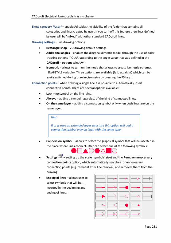
CADprofi Electrical: Lines, cable trays - scheme
Page 231
Show category *User*– enables/disables the visibility of the folder that contains all
categories and lines created by user. If you turn off this feature then lines defined
by user will be "mixed" with other standard CADprofi lines.
Drawing settings – line drawing options.
Rectangle snap – 2D drawing default settings.
Additional angles – enables the diagonal dimetric mode, through the use of polar
tracking options (POLAR) according to the angle value that was defined in the
CADprofi – options window.
Isometric – allows to turn on the mode that allows to create isometric schemes
(SNAPSTYLE variable). Three options are available (left, up, right) which can be
easily switched during drawing isometry by pressing the F5 key.
Connection points – when drawing a single line it is possible to automatically insert
connection points. There are several options available:
Lack – no symbol on the line joint.
Always – adding a symbol regardless of the kind of connected lines.
On the same layer – adding a connection symbol only when both lines are on the
same layer.
Connection symbol – allows to select the graphical symbol that will be inserted in
the place where lines connect. User can select one of the following symbols:
Settings – setting up the scale (symbols’ size) and the Remove unnecessary
connection points option, which automatically searches for unnecessary
connection points (e.g. remnant after line removal) and removes them from the
drawing.
Ending of lines – allows user to
select symbols that will be
inserted in the beginning and
ending of lines.
Hint
If user uses an extended layer structure this option will add a connection symbol only on lines with the same type.

CADprofi Electrical: Lines, cable trays - scheme
Page 232
Settings – setting up the scale (symbols’ size) and the Remove unnecessary
connection points option, which automatically searches for unnecessary symbols
of line endings (e.g. remnant after line removal) and removes them from the
drawing.
Advanced Ortho – in this mode between the indicated points, two or three orthogonal
segments are being drawn. This mode automates the process of connecting
objects or lines while maintaining a right angle between the segments.
2 segments – creates a line consisting of two segments.
3 segments – creates a line consisting of three segments.
Advanced ortho 2 segments Advanced ortho 3 segments
Draw with polyline – enables/disables drawing line segments as polyline.
End automatically – enables/disables automatic ending of lines when the drawn line is being
connected to a different object in the drawing.
Pop-up menu – options menu for selected
element/category which is available by clicking
the right mouse button. Commands included in
the menu are similar to the commands available
on the dialog window toolbars.
Notice
Advanced ortho mode is available only in certain CAD
programs.
The first drawn segment can be vertical or horizontal depending
on which way of the mouse movement is performed after selecting the first point (P1) of the drawn line.

CADprofi Electrical: Lines, cable trays - scheme
Page 233
Procedures Drawing schematic lines
1. Run the Cable, cable trays - schematic command.
2. (Optional) Select the line and click the OK button in order to allow the drawing of a
single line without making changes in the settings.
3. In the newly opened dialog window pull-down the category that contains the
desired line kind.
4. Select the desired line and click the Add element to a list button, or double
click on it in order to put it on the List of selected lines.
5. (Optional) Repeat steps 2 and 3 in order to add more lines to the list.
6. (Optional) Using the Copy selected rows , Remove selected rows buttons
add or remove the selected line from the list.
7. (Optional) Using the Move selected rows down /Move selected rows up
buttons change the order of the lines on the list.
8. (Optional) Fill the information about type of line, enable/disable the Draw by type
option.
9. (Optional) If there is more than one line on the List of selected lines specify the
Spacing value.
10. Specify the way how you will draw the line and specify the Offset value if needed.
11. (Optional) If on the List of selected lines there is only one object then change the
Drawing settings.
12. (Optional) If on the List of selected lines there is only one object you can set the
connection and line endings options.
13. Enable/disable the End automatically option.
14. Click the OK button in order to start drawing a line (or several lines).
15. Specify the starting point and next segment points that you want to draw. In order
to finish click the Enter key.
Schematic lines are simple lines or polylines that's why it is also possible to draw lines with
the CAD program standard commands such as Line or Polyline. However, it should be noted,
that lines drawn in this way should be placed on appropriate layers. In order to match
Notice
Offset, additional angles, adding connection points, endings of lines, advanced ortho and end automatically options are
available only when a single line is selected.

CADprofi Electrical: Lines, cable trays - scheme
Page 234
properties (e.g. layers), between the drawing objects, the Match properties (_MATCHPROP)
command located in the CAD program can be used.
Drawing risers (vertical lines)
In schematic lines it is possible to present vertical lines segments using special symbols, such
as risers.
Despite the fact that risers are being inserted using the Symbols - other (check page 257)
command, program treats them as schematic lines.
For risers user should specify the type
of line and height (length of vertical
line segment). Line type can be
selected from the list that will be
available after pressing the Browse
button. Thanks to this, their diameter
data and length are being included in
BOMs.
Data that is saved in the riser is included during the BOM creation when user uses the
„Electrical – schematic cable trays” template (check page 57).
Installation view
Hint
The „Schematic lines – edit” command is used to edit type of lines (check page 67).

CADprofi Electrical: Lines, cable trays - scheme
Page 235
Scheme with risers view
Lines BOM view
Linetype scale for lines
Each line is being drawn with different line patterns,
such as a dashed line (DASHED) used for the "Return"
line. The line pattern density is set using the CAD
command: LTSCALE (_LTSCALE). By default new drawings
have got a linetype scale factor set as 1.00. If this
factor number is too small or too big then line pattern
may not be visible and all lines will be seen as drawn
with a continuous line.
LTSCALE = 200
LTSCALE = 50
In CADprofi program it's possible to design in units set as millimeters, centimeters or meters.
For this reason, when drawing schemes the linetype scale should be always adapted to the
edited scheme. For example, when drawing a scheme with the unit set as "millimeters" with
symbol's size set as 200 then the linetype scale factor should be between the 50 and 200
range.

CADprofi Electrical: Lines, cable trays - scheme
Page 236
Defining new user lines
User can add his own type of lines to the program. In this way, program can be adapted to
user's needs and can be used in a variety of projects in which it is necessary to draw schemes.
Procedures Adding new lines in the database
1. Run the Cable, cable trays - schematic command.
2. Click the Define new button in order to add a new line to the existing database.
New element will be added to the *User* category. A new Edit window will open,
in which user will be able to specify all line parameters.
3. (Optional) Select an existing line and click the Copy button to create a new
item. Selected line will be used as a template.
4. Change the new line settings in accordance with the Edit line data procedure.
*Favourites* category
It is also possible to create a folder that contains a list of most frequently used installations by
the user. This folder is created automatically when a first element marked as favorite has
been added to the program. In the *favorite*category user can define any branch structure,
in which the individual elements will be located.
Edit line data
CADprofi allows to edit parameters (drawing features) of lines created by user. To do this, use
the Edit option.
In CADprofi program pipe and ventilation lines can be drawn as schematic (with use of lines
or polylines) or in 2D view. Therefore, when editing properties it is possible to specify
different parameters for schematic lines as well as for lines in 2D view.

CADprofi Electrical: Lines, cable trays - scheme
Page 237
Edit line data dialog window
The Edit dialog window contains the following items:
Name – name of edited line.
Text notation – text marking for lines used as an ending of layer’s name in the extended layer
structure.
Notice
It is recommended to use „unique values” of text notations in
order to ensure proper recognition of lines by CADprofi.
Category – currently assigned category in CADprofi database.
Branch – currently assigned industry branch in CADprofi database.
Add to most recently used – this option adds the edited line into the default list of line types
in the in the 2D Pipes – plan dialog window.
Lines or 2D lines – settings used for schematic lines or lines drawn in 2D:
Line color – determines the line color. Color can be selected in several ways: by
clicking on the button that contains the line preview, with the help of the by layer
option or by entering CAD program color number.
Line type – determines the line type (kind). Line type can be selected from the list
of available line types or from the by layer option.

CADprofi Electrical: Lines, cable trays - scheme
Page 238
Line weight – determines the line width. Line width can be chosen from the list
available values in the program.
Notice
Only lines defined by user may be edited (it is not possible to
change line parameters from the primary CADprofi database).
Procedures Edit user lines
1. Run the Cable, cable trays - schematic command.
2. (Optional) If the line that you would like to edit is located on the list of selected
lines, then select it and click the Remove selected rows button in order to
remove it from the list.
3. On the List of available lines select the line that you would like to edit.
4. Click the Edit .button A new dialog window will open, allowing you to edit the
line.
5. (Optional) Change the Name of edited line.
6. (Optional) Change the Text notation of edited line (not recommended if the edited
line is already inserted in the drawing).
7. (Optional) Change Category of edited line.
8. (Optional) Change the Trade for selected line.
9. (Optional) Enable/disable the Add to most recently used option.
10. (Optional) Change parameters of schematical Lines.
11. (Optional) Change parameters of schematical 2D Lines.
12. Click the OK button to accept the changes.
Notice
If you have changed the parameters for lines that have already
been added to the drawing then in order to update their properties you will need to insert a new line (that has the new parameters) into the drawing.

CADprofi Electrical: Lines, cable trays - scheme
Page 239
Installations from drawing
All lines and polylines that lie on appropriate layers are treated by CADprofi program as
schematic lines. This includes layers with names similar to 2DX_PLS_xxx.
When several designers are working on the same project, then it is possible that one of these
designers has used his own line kinds and then has forwarded the drawing to further edition.
In this case, CADprofi application will automatically detect the presence of additional lines
(installation kinds) and will display them in a new category called Installations from drawing.
Name of the new lines that were identified from the drawing are being taken from their label
(ending of the layer's name). If these lines' parameters will be edited in the dialog window,
then they will be permanently saved in the program's database as user's lines.
It is possible to use Installations from drawing
without the need of editing them, but in this
case, on all BOMs the Installations from
drawing lines will have their names listed as
their layers' label.
Lines’ layers
Each line kind is being drawn on separate layers. In order to easily manage layers in the top
menu of CADprofi programs are located additional commands that allow to quickly hide or
show all layers that belongs to central heating, sewage, water and other kinds of installations.
In the C:\Cadprofi\X.x\PlotStyle printing styles are located that suit the program's layers
structure. Out of these files user can select monochrome printing (CADprofi Mono.ctb) and
color printing (CADprofi Color.ctb).
*.ctb files should be copied to the appropriate folder of used CAD program.
For more information, please refer to the layers section (check page 32).

CADprofi Electrical: Working with symbols – general rules
Page 240
Working with symbols – general rules CADprofi program possesses several commands used for inserting symbols into the drawing.
It is possible to insert symbols in any point, into lines, as well as the simultaneous insertion of
multiple symbols in the drawing.
CADprofi symbols have certain properties, thank to which they behave in a "smart" way, for
example automatically adjust the insertion angle to the line, automatically break the line at
insertion point, adjust the layer depending on the kind of installation etc.
All symbols available in CADprofi program are being inserted as blocks, which can be copied,
deleted or edited with the use of standard CAD program commands. Most symbols can be
also edited with the use of CADprofi editing commands such as: Quick edit, Edit symbols and
Delete symbols.
Symbols are often used to graphically represent real devices, armature and other installations
elements, therefore it is possible to add technical parameters, about the products used in the
project, to the symbols (Attributes and descriptions command), as well as numbering and
symbols' marks. This information can be used when describing drawings when creating
graphical legends or specifications (check page 46).
Symbols and Marks commands are used to insert symbols into the drawing.
Each command that is used for working with symbols has got
a variety of options used insertion of single or multiple
symbols into the drawing.
Main options (available after pressing the button):
Insert symbol or symbols.
Into many lines.
In extension.
Into point.
‘Insert symbol’ option
This is the default option that allows to insert symbols in any point or into a line indicated by
user.
Insert into a line Insert in any point

CADprofi Electrical: Working with symbols – general rules
Page 241
Procedures Insert symbol
1. Select the symbols or symbols in any library.
2. Click the Insert symbol button. The library dialog window will close allowing
insertion of symbols into the drawing.
3. Point into a line, in which you would like to insert the symbol.
4. (Optional) Click anywhere in the drawing to insert a symbol.
5. (Optional) Specify the rotation angle of inserted symbol - this option is available
only if user has selected the Rotate option in the library dialog window.
When inserting symbols into lines, the symbol insertion angle depends on the line angle (the
angle specified in the dialog box is being ignored).
In this case, if user selects the Rotate option then he will be able to specify symbol's rotation
relatively to the line. This option is very convenient when inserting symbols which have a
possibility to determine their tap direction, handle position, flow direction etc.
The angle of such symbol will be dependant on the position of P2 point.
Without rotation With rotation
‘Into point’ option
The Into point option may be used when it is necessary to insert the symbol in a point that
lies on a line, but in such a way that the symbol won't "adjust itself to the line". In this option,
the inserted symbol "ignores" the line, so it does not break it and it does not take angle from
it. This option is used in many situations for example when inserting sensors, which usually
need to touch lines.
Inserting symbol in a point (line was ignored)

CADprofi Electrical: Working with symbols – general rules
Page 242
Procedures Insert into indicated point
1. Select the symbols or symbols in any library.
2. With the use of button, pull-down the insertion list.
3. Click the Into point button. The library dialog window will close allowing insertion
of symbols into the drawing.
4. Point into a point in a line, in which you would like to insert the symbol.
5. (Optional) Click anywhere in the drawing to insert a symbol.
6. (Optional) Specify the rotation angle of inserted symbol - this option is available
only if user has selected the Rotate option in the library dialog window.
‘In extension’ option
The In extension option allows to precisely specify the symbol insertion point in relation to
other objects located in the drawing. This allows to insert a symbol in a point in accordance
with for example another symbol.
Inserting in extension
Procedures Insert in extension
1. Select the symbols or symbols in any library.
2. With the use of button, pull-down the insertion list.
3. Click the In extension button. The library dialog window will close allowing
insertion of symbols into the drawing.
4. Click a line, in which you would like to insert the symbol (P1).
5. Program will determine a point at the line beginning (P1’). Specify the offset
against this point or specify the symbol insertion point against you would like to
specify the location of the inserted element (P2).
6. Specify an additional offset or click Enter to confirm the insertion point.
7. (Optional) Specify the rotation angle of inserted symbol - this option is available
only if user has selected the Rotate option in the library dialog window.
8. Symbol will be inserted in the drawing and the command will end (if user has not
selected the Insert multiple option).

CADprofi Electrical: Working with symbols – general rules
Page 243
‘Into many lines’ option
Into many lines option gives the possibility to quickly insert selected symbol into many lines.
It allows to insert selected symbol into all lines that cross with the „indication line”, that was
specified during insertion (P1–P2).
Inserting symbols into many lines
Procedures Insert into many lines
1. Select the symbols or symbols in any library.
2. With the use of button, pull-down the insertion list.
3. Click the Into many lines button. The library dialog window will close allowing
insertion of symbols into the drawing.
4. Specify the first point of the “crossing line” that will cross with lines (P1).
5. Specify the second point of the “crossing line” that will cross with lines (P2).
6. The selected symbol will be inserted in all lines that crossed with the “crossing
line”.
Schemes: working with symbols
Usage of symbols inserted with a fixed angle
In order to maintain the project correctness, some symbols are being inserted with a fixed
angle. Examples include gravels and separators. These symbols should be inserted with a 0°
angle. In CADprofi many symbols have got an enforced insertion angle. When user will insert
such symbols in horizontal or vertical lines, these lines will automatically break. In other cases,
lines are not being broken.

CADprofi Electrical: Working with symbols – general rules
Page 244
Vertical line Horizontal line Incline line
Symbols that contain text (visible attributes)
For symbols that contain text (visible attributes) CADprofi program will automatically adjust
angle of the text. Thanks to this the situation in which text would be displayed "upside down"
or "backwards" is being avoided. User has the following possibilities to adjust texts:
0° fixed angle.
0° or 90° angle. If symbol is inserted with a 90° angle, then the text is also rotated
by 90°. In other cases the text angle is 0°.
Automatic angle from -30° to +120°. In these ranges the text rotation angle is
sufficiently readable.
Adjustment of attributes angle
Notice
Options for text adjusting are permanently set for each symbol. User can change these options only for symbols that were
added by the user.
Notice
For symbols with a fixed insertion angle, "Angle" and
"Rotation" options located in the dialog box are being ignored.

CADprofi Electrical: Working with symbols – general rules
Page 245
Find symbols
In each dialog window that is used for symbols insertion there is a search option, thanks to
which it is possible to quickly find desired symbols.
The Find field is used to enter a phrase (full or just a part
name of searched symbol). This field remembers typed
words, which allow user to search again from the
expanded list by pressing the button and clicking Find..
After filling the search field, application will automatically filter the current library content
and display only those categories which contain the objects that match the search results.
Clicking the Restore button will display all library objects and end the search.
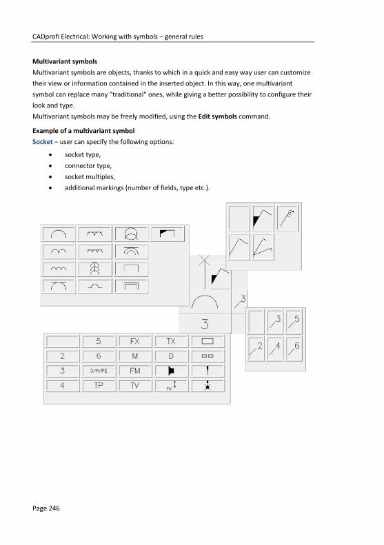
CADprofi Electrical: Working with symbols – general rules
Page 246
Multivariant symbols
Multivariant symbols are objects, thanks to which in a quick and easy way user can customize
their view or information contained in the inserted object. In this way, one multivariant
symbol can replace many "traditional" ones, while giving a better possibility to configure their
look and type.
Multivariant symbols may be freely modified, using the Edit symbols command.
Example of a multivariant symbol
Socket – user can specify the following options:
socket type,
connector type,
socket multiples,
additional markings (number of fields, type etc.).

CADprofi Electrical: Working with symbols – general rules
Page 247
Management of symbols content
CADprofi program possesses several thousands of symbols grouped in appropriate categories.
Witch such a large number it is sometimes hard to find symbols needed at the moment. On
the other hand, when working on a particular project it is usually not needed to work with
more than several dozens of symbols. In order to speed the work, user can add selected items
to the *Favourites* category thanks to which he will be able to get a much faster access to
them.
It is possible to create sub-categories related to a specific theme, such as a separate category
for symbols used in designing telecommunication, lighting installation and more. Furthermore
one element can be added to many sub-categories.
For elements placed in the *Favourites* category it is possible to change their name, which
will be later used in BOMs, legends and descriptions. Change of name can be also used to user
own translations for some symbols from international standards.
Adding symbols to favourites
Add to favourites button allows to copy any symbol to the *Favourites* category. This
folder is created automatically after user has copied the first symbol.
Changing the symbol name
Initially, each copied symbol receives the
default name from the original item.
In order to change the symbol name that
is located in the *Favourites* folder, user
should first select it and then press the F2
button to activate the edition mode
Notice
Changed name will be visible in tables and descriptions that are
created with the „Bill of materials” (check page 46) command.

CADprofi Electrical: Working with symbols – general rules
Page 248
Changing category
In order to change or define a new
category, click the right mouse button on a
desired symbol and from the context menu
choose the Change category option.
In the dialog box, user can select an existing
category or enter a new category name.
After accepting, selected symbol will be
moved to the defined category.
CADprofi application allows to create many
copies of each symbol and it is possible to
place them in different categories. Thanks
to this user can create categories that
group symbols of a specified type or the
most common used symbols for a given
industry type.
Changing the category or many symbols
If user is editing a symbol in his native
category in which there are many symbols,
then CADprofi application will change
category for all these symbols.
Deleting symbols
It is possible to delete symbols from the *Favourites* category. To do so, select the symbol
and choose the Delete option from the dialog window.

CADprofi Electrical: IEC, NFPA symbols
Page 249
IEC, NFPA symbols The Symbols - IEC, NFPA command allows to insert controlgear, switchgear, complex
apparatus, measuring instruments and many additional symbols and elements that are used
in electrical installations scheme. In the library there are symbols from both IEC and NFPA
standards available.
During the symbol insertion it is possible to automatically enumerate objects and determinate
connections as well as add information about additional technical parameters.
Inserting symbols into lines will automatically interrupt them in the insertion point, while
maintaining the principles of creating schematic drawings. This rule also applies to multipole
apparatus, but in this case, user has to match the line to the type and scale of multipolar
symbols.
Inserting an IEC multipole symbol
Inserting a NFPA multipole symbol
For IEC symbols the offset between each lines is 5 (or a multiple of 5), whereas for NFPA
symbols it is 3/8” (0.375).
Hint
Templates for potential lines and line circuits that are available in the „Frames and tables” (check page 266) command have been prepared in such a way allow the correct insertion of
multipolar symbols, on condition that they have the appropriate scale.

CADprofi Electrical: IEC, NFPA symbols
Page 250
Symbols – IEC, NFPA dialog window
The Symbols - IEC, NFPA dialog window contains the following items:
Attributes visibility – this option is used to specify which attributes should be visible when
inserting symbols.
After clicking the button, a dialog
window will open with a list of available
attributes.
Editing the attributes can be performed
after the symbol insertion by using the
Attributes and descriptions (check page
34) command or by using the DDEDIT
(_DDEDIT) command in the CAD program.

CADprofi Electrical: IEC, NFPA symbols
Page 251
Tools menu:
Define new – allows to add a new element to the database. Read more about it
in the Defining user blocks (check page 89).
Edit – allows to Editing user block parameters (check page 92).
Add to favourites – copies symbol to the *Favourites* (check page 248).
Delete – deletes the selected symbols from the *Favourites* category.
Pop-up menu– options menu for the selected symbol,
which is available after right clicking on the
mouse button on the selected symbol.
Commands in this menu are similar to the tools
menu.
Categories tree – a set of all categories and symbols in the library, shown as a pull-down tree.
User can customize the display order by using the following options:
Sort – alphabetical order of categories placement and their content.
Show norms– enables/disables displaying symbols according to norms.
Thumbnail view – displays the content of currently selected category as thumbnails.
Preview – displays the preview of the currently selected symbol. Right-clicking on the preview
window will zoom the view.
Mirror X, Y – enabling this option will create an X or Y mirror image for the specified object.
Angle/Rotation – possibility to specify a fixed angle when inserting symbols or enabling the
rotation option, in which symbol's angle is defined by rotation during insertion
During insertion of symbols into lines, the insertion angle depends on the line
angle (the angle specified in the dialog window is being ignored). When inserting
symbols into lines it is possible to use the Rotation option in order to dynamically
specify symbol rotation relatively with the line.
0° angle Rotation
30° angle Inserting into a line without rotation

CADprofi Electrical: IEC, NFPA symbols
Page 252
Scale – specifies the size of inserted symbols. It is possible to enter the scale value or to
indicate a symbol on the drawing whose scale user would like to use.
System – if in the program options, the extended layer name structure (check page. 29) is
enabled then symbols will be inserted on layers depending on the kind of installation
(system). In case of inserting symbols into an existing line then the System option is
being ignored and the symbol layers depends on the line kind.
Object data – this option allows to specify symbols technical or identification parameters. For
each symbol, different parameters can be given such as: Article, Manufacturer,
and others. Available options and parameters depend on the symbol type.
Remember data– this option allows to save the user entered parameters. This option should be
enabled when user inserts symbols with similar characteristics.
Label – gives the possibility to add subsequent labels to inserted symbols. Label field is
automatically filled with default marking and the first free number. Thanks to the
available buttons, user can choose between the first free number and a
subsequent number . This field can be also filled with any value.
Fill pins – numbering of connections in the inserted symbol. Numbering type can be chosen
from the drop-down list:
Auto – numbering of all connections, starting from number 1.
1/2… or a/b… – allows to possibility to manually number connections. This option
allows user to enter values himself for subsequent connections, separating them
with the”/” sign.
Automatic numbering Numbering: A1/A2/1/2/3/4/5/6/13/14.
Insert multiple– enables/disables the possibility of inserting multiple symbols to the drawing.
The insertion process requires from the user to press the Enter or Esc key when he
finished inserting multiple symbols.
Some apparatus symbols are multivariant symbols, thanks to which user can insert to the
project apparatus that contain any configuration of contacts, triggers etc. Such symbols
Hint
Entering the "//" characters in the numbering field will allow to
bypass the next connection.

CADprofi Electrical: IEC, NFPA symbols
Page 253
substitute many "traditional" symbols in the library. In this way it's easier to use the program,
and at the same time it gives user more opportunities to define custom elements.
Multivariant symbols can be edited with the Edit symbols command.
Example of a multivariant symbol
contact selection
trigger selection
mechanism selection
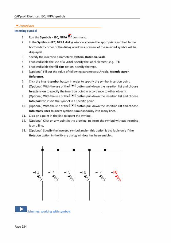
CADprofi Electrical: IEC, NFPA symbols
Page 254
Procedures Inserting symbol
1. Run the Symbols - IEC, NFPA command.
2. In the Symbols - IEC, NFPA dialog window choose the appropriate symbol. In the
bottom-left corner of the dialog window a preview of the selected symbol will be
displayed.
3. Specify the insertion parameters: System, Rotation, Scale.
4. Enable/disable the use of a Label, specify the label element, e.g. –F8.
5. Enable/disable the fill pins option, specify the type.
6. (Optional) Fill out the value of following parameters: Article, Manufacturer,
Reference.
7. Click the Insert symbol button in order to specify the symbol insertion point.
8. (Optional) With the use of the button pull-down the insertion list and choose
In extension to specify the insertion point in accordance to other objects.
9. (Optional) With the use of the button pull-down the insertion list and choose
Into point to insert the symbol in a specific point.
10. (Optional) With the use of the button pull-down the insertion list and choose
Into many lines to insert symbols simultaneously into many lines.
11. Click on a point in the line to insert the symbol.
12. (Optional) Click on any point in the drawing, to insert the symbol without inserting
it on a line.
13. (Optional) Specify the inserted symbol angle - this option is available only if the
Rotation option in the library dialog window has been enabled.
Schemes: working with symbols

CADprofi Electrical: Process control symbols
Page 255
Process control symbols The Symbols - process control command allows to design control-measurement systems and
industrial automation by using multivariant symbols such as measuring points, sensors,
transmitters, controllers etc.
Each, individual points (elements) of the scheme can be automatically numbered. They are
also used to determine various markings.
Symbols – process control dialog window
Basic functionality and options regarding symbols are described in the Symbols - IEC, NFPA
(check page 250) chapter. Additional options for the Symbols - process control:
Numbering and marking fields – for each symbols different fields are available, that are used
to add additional markings, symbols variants or numbering.
Special symbols codes field – gives the possibility to display the code of the selected symbol
so it can be copied and pasted anywhere into a text field.
List of symbols is available after pressing the button.
Leader – enables/disables usage of leader for descriptions. By clicking on the button,
that symbolizes the currently set arrow type, user can change the following leader
settings:

CADprofi Electrical: Process control symbols
Page 256
Arrow type– symbol that is inserted in the leader starting point for example an
arrow.
Arrow size – determines the leader scale.
Insert single segment –drawing of a one or multi-segment leader.
Procedures Inserting a marking (multivariant symbol)
1. Run the Symbols - process control command.
2. In the Symbols - process control select the desired symbol.
3. (Optional) Specify additional markings, numbering method etc.
For certain fields you can select the value from the drop-down list.
The button will allow you to select the value in an additional window.
4. Specify the rotation Angle and Scale.
5. (Optional) Enable and change Leader settings.
6. Enable/disable the Insert multiple option.
7. Click the Insert symbol button, to insert the marking into the drawing.
8. Symbol can be used to mark other objects, therefore indicate an object. Depending
on the selected marking type, from the selected object user can retrieve data that
can be used in the inserted marking.
9. Wskaż punkt wstawienia symbolu oznaczenia.
10. (Optional) Specify the symbol rotation angle.
11. Symbol will be inserted in accordance to the selected settings.
12. (Optional) If in the dialog window the Insert multiple option is enabled then repeat
the steps 8-11 in order to insert an additional mark or end the command by
clicking the Esc key.

CADprofi Electrical: Symbols - other
Page 257
Symbols - other The Symbols – other command contains many symbols that are used in both projections and
electrical schemes. Many categories are available, including:
connecting apparatus,
symbols used for plans designing (connectors, sockets etc.),
measuring instruments,
equipment for fire protection and fire fighting,
alarm installations,
telecommunications,
and many more.
User can add the most frequently used symbols to the *Favourites* category thanks to which
sure will have a quicker access to them. When selecting symbols, user can also use the find
function .
Symbols – other dialog window
Full functionality and all options regarding symbols are described in the Symbols - IEC, NFPA
(check page 250) chapter.
Sockets and connectors

CADprofi Electrical: PLC controllers
Page 258
PLC controllers The PLC controllers command allows to insert to the project any kind of configured blocks of
PLC controllers. This command also allows to define any number and type of inputs/outputs,
their number and address (numbering).
Block of multivariant controllers are symbols for which it is possible to specify all dimensions
and customize their appearance and technical parameters. Basic functionality and all options
regarding symbols are described in the Symbols - IEC, NFPA (check page 250) chapter
When defining a PLC controller block, user should specify its exterior dimensions, and the
number of inputs/outputs. After inserting a block, user can describe each inputs/outputs with
the help of appropriate signs.
Examples of frequently used controllers configurations, which may be used as a basis in
designing user own systems are available in the command.
After inserting the controller into the project it is possible to edit it by using the Edit symbol
command.

CADprofi Electrical: PLC controllers
Page 259
In the dialog window that is used for defining controllers there are active fields and buttons
that allow to freely define various parameters.
Examples of fields and buttons that are used in the dialog window.
1. Dimension field – allow to determine the dimension by entering the value or by
indicating two points in the drawing ( button).
2. Drop-down list – gives the possibility to enter your own value or to select data
from the list by pressing the button.
3. Text field – gives the possibility to enter any text.
4. Label – gives the possibility to add subsequent labels to inserted symbols. Label
field is automatically filled with default marking and the first free number. Thanks
to the available buttons, user can choose between the first free number and a
subsequent number . This field can be also filled with any value.
5. Graphical drop-down list – expands the pop-up menu and gives the possibility to
choose one of available graphical markings.

CADprofi Electrical: Symbols of maps, lines and pillars
Page 260
Symbols of maps, lines and pillars The Symbols – maps, lines, pillars command contains a library of symbols, objects and
markings that are used in transmission networks and telecommunications drawings.
In the Telecommunication category user can find symbols that are used to design copper and
fiber networks on maps, as well to create network schemes. Elements that are used in
representing the existing, projected and dismantling status are available in the program.
Marking symbols are specially designed for the telecommunication branch and allow to
quickly describe objects on maps and schemes.
When designing networks, lines that are in the Cable, cable trays - schematic command are
also used. Pipe protective casings are available in the 2D Cable trays command.
Symbols – maps, lines, pillars dialog window
Basic functionality and all options regarding symbols are described in the Symbols - IEC, NFPA
(check page 250) chapter.

CADprofi Electrical: Symbols of maps, lines and pillars
Page 261
Network scheme example
Example of a network scheme on a map

CADprofi Electrical: Descriptions
Page 262
Descriptions The Descriptions command allows to insert into the project various descriptions that are used
in schematic drawings, and in 2D views.
Automatic descriptions
In CADprofi program there are commands that are used to describe and number objects.
These commands allow to specify technical and identification parameters, which are later
used in creating BOMs and gathering various information about the project. Parameters that
are added to the objects can be also used in automatic or semi automatic drawing
descriptions.
Symbols that retrieve information from objects and insert appropriate descriptions are used
for that. When inserting automatic descriptions user has to indicate the described object and
next specify the description insertion point.
For some symbols it is possible to enable the option to insert them with a leader.
To describe various object user should use appropriate symbols. For example Line type
description can be used to describe schematical lines. If user uses this symbol to describe
other objects, CADprofi program won't be able to read the needed data. In this case, the
symbol will be described incorrectly.
If it's necessary to describe multiple objects, it's convenient to select the Insert multiple
option.
Example of automatic descriptions

CADprofi Electrical: Descriptions
Page 263
Descriptions dialog window
Basic functionality and options regarding symbols are described in the Symbols - IEC, NFPA
(check page 250) chapter. Additional options for the Description command:
Text height – specifies the marks text height and scale. User can enter a value or indicate it
from the drawing (indicate two points).
Leader – enables/disables usage of leader for descriptions. By clicking on the button,
that symbolizes the currently set arrow type, user can change the following leader
settings:
Arrow type– symbol that is inserted in the leader starting point for example an
arrow.
Arrow size – determines the leader scale.
Insert single segment –drawing of a one or multi-segment leader.
Precision of dimensions – defines the precision (decimal number) of all values of dimensions
that are placed in marks. These dimensions are automatically retrieved from the
indicated object.
Background mask – enables/disables the possibility to mask the symbol background by
adding a WIPEOUT. This feature is helpful if user needs to highlight important
information in the drawing.

CADprofi Electrical: Descriptions
Page 264
Multivariant marks and object numbering
Many mark symbols are multivariant symbols, for which user has got a possibility to
customize the appearance and to select additional options. For these symbols in the dialog
window there are selection fields and text fields buttons available that allow to specify the
variant or adoption of symbol to current needs.
An example of such multivariant symbol is the "Objects numeration" symbol. This symbol can
number objects and also retrieve from them required parameters (e.g. name, type etc.). In
this way it is possible to quickly number many objects and insert required text in the drawing.
CADprofi program automatically detects
numbered objects in the drawing, thanks to
which in the dialog window the first
available number from the specific branch
(e.g. EL - electrical installations) is being
displayed. The button allows to select
the next highest number.
By adding different number prefixes, user can create many numbered sequences (e.g. one F1,
F2, F3 sequence for switches and one K1, K2, K3 for relays).
Inserting symbols with the Insert mupltiple option will cause the symbols to have numbers
added to them with increased numeration.
The Mark 1, Mark 2 fields allow to add in the selected symbol any text or information
retrieved from the indicated object. Selecting the information type will be possible after
pressing the button that is located next to the field.
In the newly opened window user can
select the following information:
Attributes – indicated object
attributes values.
Lines – line type or installation
kind.
Dimensions – dimensions
retrieved from the indicated
object.
Others – for example the CAD
program system variable
values.

CADprofi Electrical: Descriptions
Page 265
Procedures Inserting an automatic description (multivariant symbol)
1. Run the Descriptions command.
2. In the dialog window select the appropriate description symbol.
3. (Optional) Change the data type by clicking the Browse button and select the
data from the list of available data in the Select dialog window.
4. Specify the parameters: Angle, Mirror and Scale.
5. (Optional) Enable and change Leader settings.
6. Enable/disable the background mask.
7. Enable/disable the Insert multiple option.
8. Click the Insert symbol button, to insert the desired mark into the drawing.
9. Indicate the symbol/object whose data should be inserted into the drawing.
10. Indicate the mark insertion point.
11. (Optional) If the Insert single segment option (in the leader settings) is turned on
then indicate a series of points that are segments ends or click the right mouse
button to continue.
12. (Optional) Specify the mark rotation angle.
13. (Optional) If in the dialog window the Insert mulptiple option is enabled then
repeat the steps 10-13 in order to insert an additional mark or end the command
by clicking the Esc key.
An example of a description (marking) with number,
object name (Name attribute) and type (Article attribute).
E1 Triple binding OKW 318 3X18W

CADprofi Electrical: Frames and tables
Page 266
Frames and tables Frames and drawing tables are available in CADprofi Electrical. Various drawing tables are
also available in general CADprofi commands, but when user creates electrical projects, it is
recommended to use the tables from the Electrical module, which are specially prepared to
electrical schemes.
More information about frames and tables can be found in the Tables (check page 37)
chapter.
Circuit markings:
Frames and tables command allows to insert tables with circuit markings. These tables are
being inserted in the lower part (most often directly under the circuit scheme). Several table
arrangements are available. In the first step user should insert to the project the table header
and afterwards the tables that contain data for each circuit. In the circuit tables it is possible
to provide the circuit name and number, as well as additional parameters, such as: power,
type, security type, kind and line length.
Frames and tables dialog window
Hint:
Data from circuit tables can be used in BOMs. In the BOM creator user should select the „Electrical – summary based on
tables circuit” (check page 46).

CADprofi Electrical: Scheme templates
Page 267
Scheme templates The Scheme templates command allows to insert to the project predefined lines potentials
and circuit lines, which are used to quickly create schemes.
Predefined lines are adapted to suit both ISO and ANSI standards.
Lines potentials are parametrical, thanks to which it is possible to specify spacing between the
scheme lines.
The Scheme templates command contains predefined electrical schemes that can be used to
create typical schemes. Direct-on-line start of 3-phase motors, reversing systems, star-delta
starting and many more schemes are available.
Each scheme has got components that are initially pre-numbered. User can enable
renumbering and specify additional marks.
A special group of schemes are distribution centre - circuits. Sets that contain several circuits
are available, as well as single lighting or socket circuits. Thanks to this user can instantly

CADprofi Electrical: Scheme templates
Page 268
create various distribution centre schemes. Socket and lighting circuits can be used for other
types of circuits - after inserting such a circuit, all that user has to do is to change the
description and the receiver symbol.
When inserting distribution centres, tables that are used to specify the name, number and
circuit parameters are also inserted. To edit this data, user can use the Edit symbols
command or other commands that are used to edit block attributes.
Example of a typical scheme with insertion of an additional circuit
Schemes: sheet templates

CADprofi Electrical: Lighting
Page 269
Lighting The Objects and lighting command allows to insert typical lighting fixtures. This command
also contains sample light fixtures that were prepared on the basis of certain manufacturers
catalogs. Before using these lighting fixtures in projects it is advised to check the current offer
of these manufacturers.
Lighting fixture is also available in the Symbols - other command. However, it should be noted
that symbols are elements that contain only a representation of a specific device and
therefore do not need to have the actual dimensions. The Objects and lighting command on
the other hand gives the possibility to insert object to the project, whose dimensions match
the dimensions of actual devices.
Objects and lighting dialog window
Basic functionality and options regarding symbols are described in the Symbols - IEC, NFPA
(check page 250) chapter. Additional options for the Objects and lighting command:
Parameters – first element in each category gives the possibility to determine the
dimensions. After selecting a such element, user has to specify dimensions in the
Dimension X, Y, Z fields.
View and insertion point – for some objects additional views are be available, e.g. side views
that allow to insert objects not only on plans but also on cross-sections and other
installation views.

CADprofi Electrical: Lighting
Page 270
Procedures
Inserting a lighting fixture
1. Run the Objects and lighting command.
2. In the Objects and lighting dialog window expand the needed category.
3. In the detailed list that contains lighting fixture types a list of all available
manufacturers or series of types is available.
4. (Optional) Double click on a series of types in order to expand it and display its
content.
5. Select an element by clicking a position from the list. If the first element will be
chosen, then it will be possible to specify the X, Y and Z dimensions, which allows
to insert to the project lighting fixture with non standard dimensions.
6. (Optional) Change the View for the selected element.
7. Disable the System option or select an installation from the available list, to specify
the layer for the selected element.
8. Click the OK button to insert the selected object to the drawing.
9. Specify the insertion point and the object rotation angle.
Lighting
Hint:
If the lighting fixture should be located on a net then after inserting the first lighting fixture user can use the ARRAY
(_ARRAY) command from the CAD program.
Example of inserting a lighting fixture: After inserting the first lighting fixture, the rest
fixtures were copied by using the ARRAY command with the distance 2600 mm x 1300 mm.

CADprofi Electrical: Switchgears
Page 271
Switchgears The Switchgears command gives the possibility to insert switchgear (distribution). 2D views
(from the top) are used when designing on plans. Front views are used when designing
distribution facade.
This command allows to select the Insert (specify all dimensions) option, thanks to which
user can insert objects with custom dimensions. It is also possible to save the user dimensions
by Creating and extending the user type of series Creating and extending user type of series
(check page 88).
Switchgears dialog window
The method of working with object has been described in previous chapters.
This command also contains the following items:
Object style – options that allow to specify the object style and the level of object detail.
Insert as block –allows user to insert an element that is exploded into component
parts or a one single object (block).
With attributes – enables/disables adding of attributes to the inserted object.
Axes – enables/disables an option to draw axis in the inserted object.

CADprofi Electrical: Switchgears
Page 272
Hidings – enables/disables drawing elements that are hidden in an object.
Wipeout (covers) – enables/disables addition to the inserted elements Covers
(WIPEOUT) type objects.
Details, hatch – enables/disables drawing of hatches and object details such as
holes in the flanges, arrows that indicate the direction flow and others.
Texts– enables/disables drawing of potential texts in objects.
Object style dialog window
An example of switchgear on a plan and a facade with inserted apparatus
Designing switchgear

CADprofi Electrical: Modular units (apparatus)
Page 273
Modular units (apparatus) The Modular units command contains many types of connection apparatus, protection and
other components used in electrical projects. For all apparatus both views used when
designing switchgears and when symbols on schemes are applied. In case of inserting
apparatus views it is possible to create a list of objects to insert, which is also used to
simultaneously insert many objects to the drawing.
If user inserts symbols he should use all policies and procedures described in the Symbols -
IEC, NFPA (check page 250) chapter.
After inserting apparatus view it is possible to use the Create alternative view command in
order to obtain in a convenient way symbols for each apparatus. It is also possible to obtain
apparatus views on the basis of previously inserted symbols. Using this command user can
quickly create a scheme based on the switchgear view or vice versa (check page 64).
Modular units dialog window
The method of working with object has been described in previous chapters.
This command also contains the following items:
Objects to insert – list of objects that will be inserted into the drawing.
The Add element to a list button adds object to the list of objects to insert.
Insertion options – when inserting a single, user can use other option than the default one to
insert an object in the drawing. The button expands the list of available insertion options:

CADprofi Electrical: Modular units (apparatus)
Page 274
Insert (specify style for object) – inserts selected object with a possibility to
change options in the Object style dialog window.
Insert (specify all dimensions) – inserts selected object with possibility to specify
all dimensions that can be edited. It is also possible to save the user dimensions by
Creating and extending the user type of series Creating and extending user type of
series (check page 88).
Procedures Inserting many objects (list of objects to insert)
1. Run the Modular units command.
2. In the dialog window select the appropriate category.
3. In the detail a list of available apparatus types will be visible.
4. (Optional) Double click on a series of types in order to expand it display its content.
In order to expand all series of types click the right mouse button and from the
context menu select the appropriate option.
5. (Optional Change the View for the selected element.
6. (Optional) Change the Object style settings.
7. Select an element by double clicking or select it and click the Add element to a list
button.
8. Continue with filling the list by repeating the steps 2 - 7.
9. (Optional) Organize the list with the help of the Copy , Delete
Move selected rows down or Move selected rows down buttons.
10. Specify the label and number of the first apparatus. Next apparatus will be inserted
with consecutive numbers.
11. Click the OK or Insert from list button, to insert object into the drawing.
12. Specify the insertion point and the objects rotation angle.
Designing switchgear
Automatic obtaining of apparatus view upon symbols

CADprofi Electrical: Circuits numbering
Page 275
Circuits numbering The Circuits numbering command allows to define electrical circuits and assign them to
indicated objects (addressing objects).
CADprofi Bill of materials creator allows to prepare specifications that include the assignment
of objects to individual circuits.
This command can work in three modes:
Numbering – this mode is used to define circuits and address objects. Each object
receives a circuit number to which it will be connected.
Numbers edition – this mode allows to edit circuit numbers (addresses) for many
object simultaneously.
Numbers deleting – deletes numbers from selected objects.
During the defining of schemes program allows to indicate switchgear on the drawing, which
can be any object or symbol from the CADprofi Electrical module, e.g. an element inserted
with the Switchgear command. It is possible to define circuits, for which there is no
switchgear in the current drawing.
Example of objects with defined circuit numbers

CADprofi Electrical: Circuits numbering
Page 276
Circuit numbering dialog window
The Circuit numbering dialog window contains the following elements:
Tables and circuits in the drawing – list of tables and their circuits displayed in a form of a
drop-down tree. Symbols on the list:
Table/switch board –
Circuit type –
Circuit number –
In the bottom part of the window the information about number of objects in each circuit is
being displayed. If the main element of the tree is being selected, then a detailed list of all
circuits and objects will be visible.
Menu list of tables and switch boards – tools that are used to manage boards (switchgear).
Delete number from the table – deletes number from the block that symbolizes the
indicated board.
Indicate a table on the drawing – allows to indicate (or change) in the drawing the block
which symbolizes the indicated board.
Change the table number – allows to change the board name.

CADprofi Electrical: Circuits numbering
Page 277
Zoom on a circuit or a board – this command selects objects that are assigned to the
indicated circuit or circuits. If switchgear will be chosen, then the zoom is
performed on a drawing object (block), which acts as a board.
Test/Repair – this option allows to automatically detect and correct any possible
inconsistencies in the current circuit numbering.
It is recommended to execute this command after copying, deleting and moving
objects in order to synchronize changes with the inserted numbers.
Define or choose a circuit – a group of options that allow to define new circuits or operations
(edit and delete) the existing circuits.
Table/switch board – specifies the table marking.
Circuit type – circuit type marking.
Circuit number – circuit number.
Information about table, type and circuit number can be filled by clicking the
needed position on the list of tables and circuits.
There is a possibility to fill above data by indicating an object on the drawing,
which was already assigned to a circuit. In this case user should click the Take
circuit number from the object in the drawing .
If the edition mode is enabled, then in the Circuit defining or choosing additional
Change for field will be available.
Overwrite the numbered objects – enable/disable the possibility of overwriting an existing
numbering. This option is only available in the Numbering mode.
Options used for object editing/deleting:
Include indicated objects from the selected circuits – gives the possibility to
edit/delete addressing from selected objects.
Include all objects from the selected circuits – edits/deletes all objects that belong
to a specified circuit.
Delete numbering only from selected circuits – when this option is enabled it is
possible to delete addressing only from objects that belong to a specified circuit.
Circuits sign format – this option allows to determine the way how to show in the drawing
the information about circuit numbering. Sign template can contain any text and

CADprofi Electrical: Circuits numbering
Page 278
circuits data (<Tab> – table/switch board indication, <Type> – circuit type, <Crc> –
circuit number). During the template definition in the next field a preview is being
displayed, which will be inserted in the drawing.
Text size – specifies the circuit sign angle rotation and size.
Height – specifies the text size on printings.
Scale – specifies the text scale on printings.
Angle – specifies the circuit sign rotation angle.
Procedures Object numbering
1. Run the Circuits numbering command.
2. In the dialog window in the select the Numbering Mode.
3. In the Define or choose a circuit specify the table name, circuit type and number
or if it is possible indicate from the list a circuit to which you would like to add
objects.
4. (Optional) Enable/disable the Overwrite the numbering objects option.
5. Specify the circuit sign format.
6. Specify the Text size options.
7. Click the OK button. Window will be closed and it will allow to select objects that
will be assigned to a specific circuit.
8. (Optional) If in the table/switch board a new name was entered then the
application will propose to indicate the table on the drawing.
9. Indicate the first element that will be added to the circuit.
10. Specify the placement of the numbering marking text.
11. (Optional) Indicate objects that you would like to add to the selected circuit.
Confirm by pressing right mouse button or the Enter key. Numbering markings will
be automatically placed according with the first marking spacing.
Numbering edition
1. Run the Circuits numbering command.
2. In the dialog window in the select the Numbers Edition Mode.
3. In the Define or choose a circuit group select the table name and a circuit type and
number, from which objects you would like to edit.
4. In the Change for fields the table name and circuit type and number, for which you
would like to assign selected objects. Entering a new table name, type or circuit
number will cause a creation of a new circuit and assignation of objects to it.
5. (Optional) Enable/disable the Include indicated objects from the selected circuits
option.
6. (Optional) Enable/disable the Include all objects from the selected circuits option.

CADprofi Electrical: Circuits numbering
Page 279
7. (Optional) Specify the circuit sign format.
8. (Optional) Specify the Text size.
9. Click the OK button.
10. (Optional) If in the table/switch board a new name was entered then the
application will propose to indicate the table on the drawing.
11. (Optional) If the Include indicated objects from the selected circuits option was
enabled then indicate elements, which numbering you would like to change.
Confirm by pressing right mouse button or the Enter key.
12. Selected elements will be transferred to the indicated circuit, and their marking
will be changed.
Deleting numbering
1. Run the Circuits numbering command.
2. In the dialog window in the select the Numbers deleting Mode.
3. (Optional) Enable the Delete numbering only from selected circuits option.
4. (Optional) Enable the Include indicated objects from the selected circuits or
Include all objects from the selected circuits option.
5. (Optional) In the Define or choose a circuit card select the table name and circuit
type and number, from which you would like to delete numbering.
6. (Optional) Enable/disable the Include specified objects from various circuits or
Include all numbered objects from a drawing!!!
7. Click the OK button.
8. (Optional) If the Include indicated objects from the selected circuits or Include
specified objects from various circuits option was enabled then indicate elements,
which numbering you would like to delete. Confirm by pressing right mouse button
or the Enter key.
9. Numbering of selected elements will be deleted.
Circuit numbering (addressing)

CADprofi Electrical: 2D Cable trays and ducts
Page 280
2D Cable trays and ducts In CADprofi program it is possible to create plans and installations cross-sections that include
trays, ducts and protective tubes. When drawing an installation line elements and fittings are
available (elbows, reducers, tees etc.). Each fitting is a parametrical object, which is being
drawn with appropriate program's procedures. Thanks to this it is possible to draw any
fittings with specified dimensions. For each element, databases are available, that contain
definitions of elements of selected manufacturers.
Tray Protective tube
Trays and fittings are available in the following commands:
2D Cable trays – this command contains typical trays and fittings used when designing
cable trays.
2D Cable trays - sequence – this command allows to draw many segments with
automatic insertion of elbows.
Trays and ducts
The 2D Cable trays command allows to insert single trays or ducts to the drawing.
After running the command user has to select the needed fitting or tray, specify its
dimensions and insertion options. Program possesses functions that automate the connection
of elements to each other. It is possible to automatically adapt the tray size and connect it to
other elements. Below there are examples with usage of this function.
Examples of inserting fittings
Automatic insertion at the end of the tray.
1. Indicate a tray to which you would like to insert
an elbow (P1).
2. Specify the elbow direction (P2).

CADprofi Electrical: 2D Cable trays and ducts
Page 281
Inserting a tray with the „join object” option.
1. Indicate and object to which you would like to
connect a tray (P1).
2. Specify the length of a new tray (P2).
When connecting trays or ducts to other installation elements the Diameter fit option is
handful, cause thanks to it the inserted element always has the same size, so it will suit the
indicated object.
Z+/Z– trays and fittings
Z+/Z- trays represent the vertical tray segments (along the Z axis). On plans for such elements
the cross section symbol is also visible. Because of that Z+/Z- tray length has to be specified in
the dialog window before adding them to the drawing.
For Z+/Z- trays and fittings it is possible to additionally specify the symbol cross section (Z+, Z-
or without symbol) and the insertion point (beginning, axis, end).
Z+ Z– Without any symbol
Retrieving fittings dimensions
During drawing it is often needed to insert similar elements to elements that are already
inserted in the drawing. In such case it is convenient to retrieve dimensions from another
fitting. After pressing the Copy dimensions button user has to indicate the needed fitting. It is
important to avoid indicating fittings that have completely different parameters than the
element currently chosen in the dialog window. In such cases, user may experience ambiguity
in the data interpretation.
For example: if an elbow was selected in the dialog window, and user selects a reducer then
CADprofi won't be able to specify the elbow angle and the radius, because reducer doesn't
posses such parameters.

CADprofi Electrical: 2D Cable trays and ducts
Page 282
2D Cable trays dialog window
The 2D Cable trays dialog window contains the following items:
Categories tree – a set of all categories and symbols in the library, shown as a pull-down tree.
Preview – displays the preview of the currently selected element. Right-clicking on the
preview window will zoom the view.
Sort – enables/disables categories alphabetical order.
Fixed dimensions – enables/disables the preserve of a basic dimension after inserting objects
such reducers. After inserting such element in which the line dimension is being
reduced in the next time user runs the command the application will automatically
change the default diameter into a reduced diameter (D2). This process is very
convenient when designing an installation sequence. However, if user wants to
insert a fitting that has an unchanged main cross-section then enabling the Fixed
dimensions option will prevent an automatic change of cross-section.
Installation and drawing:
Installation – gives the possibility to choose the installation kind or define a new
one. Initially on the drop-down list only the most important CADprofi systems will
be included. However, user has the possibility to develop the list with his own
elements (by using the Add to most recently used option), which is located in the

CADprofi Electrical: 2D Cable trays and ducts
Page 283
Lines, cable trays - scheme (check page 228) dialog window. Selecting the
Others/Edit option will open a new dialog window with full list of available
systems.
Define new – allows to add
a new position (tray) to the list
as a user tray. Afterwards it
opens a new edit window and
allows user to edit the line
data.
Copy – copies the selected
line with all its parameters,
therefore creating an element
made by user.
Edit – opens the edit
properties window of user
created lines.
Delete – deletes the
selected line from the list.
Type – possibility to specify the fitting type (normal element, segment etc.).
Elbow types available in the program
Manufacturer and type – selection of items from manufacturers’ standards or databases.
CADprofi program allows to draw fittings and 2D trays, whose dimensions can be
specified in two ways:
1. Drawing based on dimensions specified by user.
To enable this mode, in the Manufacturer field select „– –”.
2. Drawing based on manufacturers’ standards or databases. In order to
activate this mode select the required manufacturer (or standard).
After selecting the manufacturer
it is not possible to enter you own
dimensions (this option is
blocked).

CADprofi Electrical: 2D Cable trays and ducts
Page 284
After selecting a specific manufacturer or standard a dialog window will
appear with available fittings or lines.
Element selection dialog window
Dimensions – In CADprofi program it is possible to draw fittings with any dimensions. To do
this, in the Manufacturer field select „– –"
When drawing is based on user selected dimensions then two field in which user
can enter values are available. button allows to select typical values. Trays
length is determined in the drawing by indicating two points.
Options – additional options that automates the drawing process:
Join object – automatic connection of inserted element to existing objects. When
connecting, CADprofi program will automatically determine the rotation angle and
the element insertion point.
Installation fit – automatic determination of installation kind based on object, to
which the inserted element is being connected. Installation kind set in the dialog
window is being ignored.
Diameter fit – automatic identification of installation diameter based on object to
which an element is being connected. In the connection point it is possible to
insert a reducer or to ignore the line diameter from the dialog window.
Insert in a sequence – gives the possibility to insert fittings into an existing line or
into their extension. If this option is disabled then fittings are inserted on the end.

CADprofi Electrical: 2D Cable trays and ducts
Page 285
Procedures Inserting a tray
1. Run the 2D Cable trays command.
2. In the 2D Cable trays dialog window from the list of available categories select
Tray, Duct or Protective tube.
3. From the list of installations select the needed kind of installation in order to
specify the color and layer for a new tray.
4. (Optional) Specify the values for the Manufacturer and type items.
5. In the Dimensions field specify the Diameter value for the tray.
6. (Optional) Click the Copy dimensions button and indicate an element on the
drawing from which you would like to copy the diameter value.
7. (Optional) Enable/disable the Installation fit, Diameter fit, and Join object.
8. Click the OK button to start drawing a tray.
Cable trays and ducts
Defining user own fittings
When designing installations it is sometimes needed
to use non-standard fittings. In this case, user can
define his own fittings, which will be taken into
account during numbering or during creating BOM.
In order to define a new additional fitting, user should
draw it first and then run the 2D Cable trays
command. After that user should choose the User
object defining option. For the newly created fitting
user should choose a name. Optionally user can also
specify the manufacturer, type and product
parameters.
After clicking the OK button, user should select
objects from the list that the new fitting is being
made up from and to choose the base point.
If a fitting is often used then it is possible to add it to
the program library by using the User block wizard
(check page 87).

CADprofi Electrical: Drawing tray sequences
Page 286
Drawing tray sequences The 2D Cable trays - sequence command allows to create trays and protective tubes
sequences with automatic insertion of elbows that have parameters defined by user (or
without elbows). This command has the ability to disable the display of the dialog box,
allowing user to immediately start drawing trays sequences with the last used settings.
2D Cable trays - sequence dialog window
Graphical layout and basic functionality of the dialog window is similar to the 2D Cable trays
(check page 282). Additional options available in this command:
Elbow parameters – a group of options that allow to specify parameters of elbows.
Radius – allows user to determine the radius or radius ratio for elbows inserted
between each tray segments.
Radius as a multiplier of width – enables/disables the possibility to determine the
radius through the width multiplier.
Type – allows user to choose the elbow type that will be used in the sequence.

CADprofi Electrical: Drawing tray sequences
Page 287
Limit max angle to 90° – enables/disables the possibility to reduce the line
sequence elbow angle to 90°.
Dimension E/Dimension F – allows to specify both E and F dimensions (that are visible on the
preview). button allows to specify the dimension by indicating two objects on
the drawing.
Reference edge – right or left edge. Edge is indicated accordingly to the drawing direction.
Procedures Inserting trays
1. Run the 2D Cable tray – sequence command.
2. (Optional) If the dialog window didn’t appear then start drawing or select the
Settings (S key) option, to change the settings.
3. In the dialog window choose the needed kind of tray.
4. Choose installation kind.
5. (Optional) Specify the values for Manufacturer and type controls.
6. Specify the line Diameter (or cross-section) for the tray or protective tube.
7. (Optional) Enable/disable the Installation fit, Diameter fit, and Join object.
8. Click the OK button to start drawing a tray sequence by indicating the points.
Cable trays and ducts
Hint
If the „Always show dialog box” option was disabled then if user wants to enable it again he has to choose Settings
(abbreviation „S” in the command line) after running the command.
Drawing direction
Left edge
Right edge

CADprofi Electrical: Drawing tray sequences
Page 288
How to draw
When drawing users should indicate points (P1, P2 etc.). If you draw by the axis and without
an offset line segments are being inserted along with the indicated points.
Protective tube Flex tube
Rectangular pipes with elbows Rectangular pipes with arches
When drawing with an offset the tray sequence is being drawn with a specified distance from
the indicated points.
An example of drawing trays accordingly to the edge and with an offset:
After drawing lines, they
were later connected with a
tee-piece using the 2D Join
pipes/ducts command
(points P7 and P8).
Drawing
direction
(P5 – P6)
Drawing
direction
(P1 – P4)
Edge: Right
Offset: 300
Edge: Left
Offset: 300

CADprofi Electrical: Drawing mesh trays
Page 289
Drawing mesh trays In CADprofi program it is possible to draw Cablofil mesh trays.
This system is available in the Manufacturers library (check page 86) command.
This command allows to draw single trays
or automatic drawing of tray sequences
with simultaneously insertion of elbows (or
without elbows). Tees and reducers are also
available.
These objects are automatically connected
to trays (one–click technology).
For more convenient edition of trays with
automatic insertion of elbows and tees the
Cablofil – Couple cable trays command
is used.
In order to enable the creation of mesh trays user can also find in the Cablofil library apart
from the basic elements also categories that include:
Mountings scheme – this category contains schemes that represent the tray mounting.
Mounting schemes are used only as graphical supplementary information. Because
of that mounting symbols are not included when creating BOMs.
In order to automatically insert mounting schemes user can sue the Create
alternative view command.
Accessories – this category includes additional elements, e.g. handles, anti fire compartments
etc. Such elements inserted to the project will be included when creating BOMs.
Some elements (e.g. clips, handles etc.) are too small to be visible on plans. Instead
of inserting many "small" objects to the project it is possible to insert a table with
additional elements. Elements with filled amount will be included in BOMs.

CADprofi Electrical: Drawing mesh trays
Page 290
To edit the amount of additional elements user can use the command to edit the
attributes or the CADprofi Attributes and descriptions command.
Couplers catalog – couplers data is included when drawing trays. Because of that there is no
need to add to the drawing couplers as graphical objects. In the couplers catalog it
is only possible to check the couplers technical data.
Trays material
During designing it is possible to specify the Cablofil mesh trays material. Program inserts
trays that are created with different materials on separate layers.
For example the 2DE_OBP_CblfEZ layer is used for Cablofil electrolytically galvanized (EZ), the
2DE_OBP_Cblf316L layer is used for trays made of stainless steel (316L).
During insertion of Cablofil elements program checks the layer name and includes only
elements that lie on layers that begin with the 2DE_OBP_Cblf. Because of that user should
not change the trays layer name.
An exception of this rule may be for example a necessity to add additional red layer for anti
fire or other special installations. For example the 2DE_OBP_CblfEZ_ppoz can be used in anti
fire installations for electrolytically galvanized trays. In such case in Cablofil BOMs instead of
material, the layer name will be visible.

CADprofi Electrical: Drawing mesh trays
Page 291
To change the material and other trays
parameters user can sue the Cablofil –
Match properties command.
To avoid misallocation of tray material it is
not recommended to change the trays layer
with the CAD program standard options.
Complex constructions
In real installations it is very often needed to conduct trays one above the other. Sometimes
such constructions can consist of many trays that are mounted to the ceiling, walls, etc. On
plans it is very difficult to represent such constructions, because many trays that overlap each
other, therefore the project becomes unreadable.
This problem is solved by "complex constructions". In this case instead of drawing many trays
that overlap, it is possible to draw a route, which shows the trays sequence and a scheme that
represents the arrangement of ducts and fittings in the route.
Example: two trays – one above the other

CADprofi Electrical: Drawing mesh trays
Page 292
2D drawing – advanced construction in CabloCAD
Complex construction scheme must contain:
1. Construction marking symbol – marking must be unique (e.g. C01, A15 etc.). In
one project it is not possible to define several complex constructions with the
same marking (ID).
2. Mounting – scheme that contains special mounting symbols. When inserting
mounting symbols the mounting spacing and construction ID must be provided
(e.g. C01, A15…).
3. Trays cross-section – when inserting mounting symbols user should also specify
the couplers type, thanks to which trays and construction markings are connected
(e.g. C01, A15…).
Trays route – when drawing a tray route it is necessary to specify its total width and height
that is occupied by all trays in the specified route.
Notice:
To a specified complex construction (e.g. C01) belong all
elements that contain the specified ID (e.g. C01). For this reason, for visual control, the ID is visible in all mounting symbols and trays cross-section. This ID is on a non-printed
layer, that's why it is visible only on the screen.
In a definition of one complex construction (i.e. one design) it
should be avoided to mix elements with different IDs. When copying elements between constructions it is necessary to
arrange IDs (i.e. construction attribute marking).
„C01” trays route
3. Trays
cross-section
1. Symbol –
„C01”
marking
2. Mounting in
„C01” construction

CADprofi Electrical: Drawing mesh trays
Page 293
It is not possible to define several same complex constructions in a project. For this reason schemes with complex construction
definition should not be duplicated. This can lead to errors when creating BOMs (duplicated elements in the drawing can duplicate the number of trays and accessories in BOMs).
If user needs to duplicate schemes of complex constructions, all copies should be "exploded" or they must have "cleared IDS"
(empty marking attribute). These copies won't be included by the program in BOMs).

CADprofi Electrical: Designing busbars installations
Page 294
Designing busbars installations Thanks to the Legrand or PiN ENERGIA library of products that are available in the
Manufacturers library (check page 86) command it is possible to create projects of busbars
installations both in 2D and 3D.
Example of a busbars installation project
Libraries content
In libraries we will find all elements
that are necessary to design
complete busbars installations.
Transformers, switchgear and
various accessories are also
available.
Hint
In order to receive a detailed bill of materials it is recommended to design busbars in 3D.

CADprofi Electrical: Designing busbars installations
Page 295
Inserting and connecting object on the drawing
Inserting objects is intuitive, and the library usage does not differ from general principles used
in designing in CADprofi program.
All busbars have appropriately defined connection points, thanks to which application can
automatically connect inserted object with an object that is already in the drawing. This
process makes it faster to design installations, especially in 3D view, freeing the user from the
hassle of determining the insertion points and rotation angles. Program also verifies the
correctness of connections, thus ensuring the correct execution of the project.
Designing busbars installations is based on insertion of elements with automatic connection
to the elements that were previously inserted. This process is repeated until the whole
installation is prepared. This design model is very smooth and quick (even in 3D), and also
includes the required precision.
When choosing objects user should pay attention to the Insertion point settings. Appropriate
selection of insertion point allows to automatically connect objects. In the event of incorrect
connection, a message is displayed informing about the lack of possibility to connect the
busbars ends, giving the possibility to rotate the connected item.
Correct object connection
Notice
Automatic object connection is available only for objects that fit
to each other – usually within the same system. When connecting, the end of the busbar is chosen that was
located closer to the point indicated by the user.
Busbars


CADprofi® Mechanical


CADprofi Mechanical: CADprofi Mechanical – Introduction
Page 299
CCAADDpprrooffii MMeecchhaanniiccaall
CADprofi Mechanical – Introduction Mechanical module helps with designing mechanical and construction projects in 2D.
This module has got a very extensive library of standardized parts, steel shapes and other
steel products developed on the basis of national and international standards. These include
bolts, nuts, washers, pins, heat exchange elements and many other elements. Scheme editor
allows to easily design hydraulic and pneumatic systems.
CADprofi Mechanical in 2 minutes
Mechanical – general commands The Mechanical command opens the dialog window from which we can choose the
appropriate commands from the Mechanical module. This command has been prepared for
beginners. In the dialog window apart from the list of all commands we can also find a large
preview window that shows the outline of the selected function.
Mechanical command dialog window
Procedures Selecting the command
1. Run the Mechanical command.
2. In the dialog window, expand the chosen category and select the needed
command.
3. Selected command will start after clicking the OK button.

CADprofi Mechanical: CADprofi Mechanical menu and toolbar
Page 300
CADprofi Mechanical menu and toolbar
CADprofi Mechanical commands
CADprofi Mechanical toolbar
Menu of CADprofi Mechanical module
Editing commands
Important editing commands used in designing can be found in the CADprofi menu and
CADprofi – Tools toolbar.
CADprofi Tools toolbar
CADprofi Mechanical: main program commands

CADprofi Mechanical: Standardized parts
Page 301
Standardized parts The Standardized parts command allows to insert to the drawing standardized elements such
as: screws, nuts, rivets, keys, bearings, wedges etc. All objects has got different views, which
allows to create cross-sections, hidings etc.
For all objects there are databases available with many national and international standards,
including: PN, EN, ISO, DIN, GOST and ANSI. It is possible to specify which standards should
be available to the user. To do this, user should select which standards should be visible in the
CADprofi - Options command (in the Standards available in the program card).
All elements are parametrical objects. It means that during inserting them into the drawing
user can specify all dimensions. This feature gives user a lot of opportunities, because with
the possibility to determine the dimensions, he can use any devices even those that are not in
the standard program databases.
Standardized parts dialog window
The Standardized parts dialog window contains the following items:
Categories tree – a list of all available elements divided into categories (standards) and
subcategories.
Detailed list – contains a list of available element types with various dimensions.
Preview – displays the preview of the currently selected element. Right-clicking on the
preview window will zoom the view.

CADprofi Mechanical: Standardized parts
Page 302
Sort – enables/disables categories alphabetical order.
Show norms – enables/disables displaying symbols according to standards.
View– object view selection. Available options depend on the selected element.
Object style – options that allow to specify the object style and the level of object detail.
Insert as block –allows user to insert an element that is exploded into component
parts or a one single object (block).
With attributes – enables/disables adding of attributes to the inserted object.
Axes – enables/disables an option to draw axis in the inserted object.
Hidings – enables/disables drawing elements that are hidden in an object.
Wipeout (covers) – enables/disables addition to the inserted elements Covers
(WIPEOUT) type objects.
Details, hatch – enables/disables drawing of hatches and object details such as
holes in the flanges, arrows that indicate the direction flow and others.
Texts– enables/disables drawing of potential texts in objects.
Specify all parameters – insertion of selected object with the possibility to specify all editable
parameters. Selecting this option and pressing the OK button will open a new
Parameters window.
The Parameters dialog window allows to specify the values of each parameter. It is also
possible to specify dimensions directly from the drawing. In such case user has to activate the
dimension field and press the Pick distance button.
Parameters dialog window

CADprofi Mechanical: Standardized parts
Page 303
Procedures Inserting objects
1. Run the Standardized parts command.
2. In the dialog window select the needed object category. After that the element
preview will be displayed and on the detailed list you will be able to see all
available element types and sizes.
3. (Optional) If the list of available types possesses subcategories double click on a
category will expand it and you will be able to see its content.
4. (Optional) Right click on any item and from the menu choose the Expand
all/Collapse all option.
5. Choose the needed element form the detailed list.
6. (Optional) Change the View for the selected element.
7. (Optional) Change the settings for the Object style options.
8. (Optional) Select the Enter all dimensions option to specify inserted objects
dimensions.
9. Click the OK button to insert selected object into the drawing.
10. Specify the insertion point.
11. Specify the object rotation angle.
12. After inserting the block user can adjust its length with a specified type of series.
Click the red support line in order to change the length or press the Enter/Esc to
accept the current size.
Normalized parts
Inserting standardized parts to the drawing
The way how to insert selected symbols into the drawing depend on its type and the chosen
view. Inserting objects, which dimensions are determined on the basis of types of series only
need to select the insertion point (P1) and specify the rotation angle (P2).
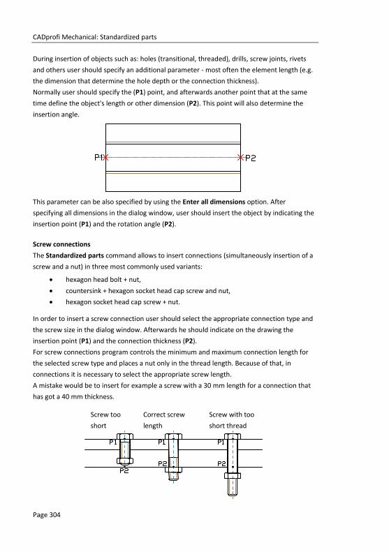
CADprofi Mechanical: Standardized parts
Page 304
During insertion of objects such as: holes (transitional, threaded), drills, screw joints, rivets
and others user should specify an additional parameter - most often the element length (e.g.
the dimension that determine the hole depth or the connection thickness).
Normally user should specify the (P1) point, and afterwards another point that at the same
time define the object's length or other dimension (P2). This point will also determine the
insertion angle.
This parameter can be also specified by using the Enter all dimensions option. After
specifying all dimensions in the dialog window, user should insert the object by indicating the
insertion point (P1) and the rotation angle (P2).
Screw connections
The Standardized parts command allows to insert connections (simultaneously insertion of a
screw and a nut) in three most commonly used variants:
hexagon head bolt + nut,
countersink + hexagon socket head cap screw and nut,
hexagon socket head cap screw + nut.
In order to insert a screw connection user should select the appropriate connection type and
the screw size in the dialog window. Afterwards he should indicate on the drawing the
insertion point (P1) and the connection thickness (P2).
For screw connections program controls the minimum and maximum connection length for
the selected screw type and places a nut only in the thread length. Because of that, in
connections it is necessary to select the appropriate screw length.
A mistake would be to insert for example a screw with a 30 mm length for a connection that
has got a 40 mm thickness.
Screw too
short
Correct screw
length
Screw with too
short thread

CADprofi Mechanical: Standardized parts
Page 305
Quick edition
The Quick edit (check page 61) command allows dynamic lengthening or shortening of some
standardized elements. For example: if in the drawing a M8 x 55 screw from the PN EN 24016
standard is inserted, then it can be lengthened or shortened to the length of 40 to 80 mm
according to the elements contained in the specified standard.
Example of a quick edition length change.
After selecting the Quick edit command and indicating the object, arrows that symbolize the
object enlargement and reduction will be visible. Clicking on the symbol will display
temporary red support lines, suggesting the user that he can change the dimensions of
selected type of series. Clicking on one of these lines will change the object into a
bigger/smaller.
Procedures Quick edition
1. Run the Quick edit command.
2. Indicate an object that was inserted with the Standardized parts command.
3. Edit an object by clicking on the lengt edit arrows symbol.
4. By clicking on the support line select a new length from the available type of series.
Notice
The disappearance of one of the tags means reaching the limit of the given types of series length.
Lack of tags mean that the object can't have the length edited.

CADprofi Mechanical: Steel shapes
Page 306
Steel shapes The Steel shapes command allows user to insert to the project all kind of steel shapes such
as: flat bars, L-shapes, U-shapes, Z-shapes etc. For all objects databases with many national
and international standards including: PN, EN, DIN and ANSI are available.
Steel shapes have got their own mass unit defined. Thanks to this it is possible to obtain
information about length and mass of elements inserted into the drawing. It is also possible
to automatically obtain the full BOM of steel (or other materials).
Most steel shapes available in CADprofi program are steel elements. Thanks to the possibility
to specify all dimensions it is possible to insert custom profiles such as aluminum, copper and
others. If custom profiles are being inserted then it is necessary to adjust the type, material
kind and unit mass or the total mass of inserted elements. The easiest way to adjust these
parameters is to use the Attributes and descriptions command which allow to simultaneously
change the data for multiple objects (check page 34).
Steel shapes dialog window
Options used in this dialog window have been described in previous chapters (check page
301).
Steel shapes available in the library have got the possibility to be inserted in a main view or in
additional views. These views are indicated in the preview window with arrows.

CADprofi Mechanical: Steel shapes
Page 307
For some views, hiding lines are included. With the help of the Object style option it is
possible to enable or disable the creation of invisible lines in the inserted object.
Main view Side view Top view
Procedures
Inserting steel shapes
1. Run the Steel shapes command.
2. In the dialog window select the needed object category. After that the element
preview will be displayed and on the detailed list you will be able to see all
available element types and sizes.
3. (Optional) If the list of available types possesses subcategories double click on a
category will expand it and you will be able to see its content.
4. (Optional) Right click on any item and from the menu choose the Expand
all/Collapse all option.
5. Choose the needed element form the detailed list.
6. (Optional) Change the View for the selected element.
7. (Optional) Change the settings for the Object style options.
8. (Optional) Select the Enter all dimensions option to specify inserted objects
dimensions.
9. Click the OK button to insert selected object into the drawing.
10. (Optional) If you decide to insert a view from the top, then in the Parameters
window specify the select steel shape length (it is necessary to later create correct
BOMs).
11. Specify the insertion point on the drawing.
12. If you decide to insert the main view specify the rotation angle. For other views,
indicate the second point thanks to which you will determine the steel shape
length.

CADprofi Mechanical: Steel shapes
Page 308
Examples of drawing with inserted steel shapes
Steel profiles are inserted as blocks. X scale for side views correspond to the profiles length. In
case of cross-sections (main views), the profile length corresponds to the block Z scale.
Thanks to this by changing the scale (X or Z) in the properties window it is possible to adjust
the profile length after inserting them into the drawing.
Closed profile with 400 mm length. Changing the profile length to 500 mm,
e.g. changing the X scale = 500
Steel shapes and metallurgical products
Hint
To display the properties window in CADprofi program, user should press the CTRL + 1 or select the appropriate command from the CAD program top menu.
P1 P2
400 mm 0.70 kg
500 mm 0.88 kg

CADprofi Mechanical: Exchangers, pipes, fittings
Page 309
Exchangers, pipes, fittings The Exchangers, pipes, fittings command contains many elements that are used in designing
heat exchangers, vessels, boilers etc. Elliptical bottoms, flanges, pipes, elbows, reducers and
other elements are available. Most elements can be inserted into the drawing in side, top and
cross-section views.
A unique program feature is the possibility to calculate the optimal distribution of the heat
exchange according to the DIN 28184–1 and DIN 28184–2 standards. It is also possible to save
the user dimensions by Creating and extending the user type of series Creating and extending
user type of series (check page 88).
Exchangers, pipes, fittings dialog window
Options covered in this dialog window were described in previous chapters (check page 301).
Designing apparatus
Drawing line sequences

CADprofi Mechanical: Exchangers, pipes, fittings
Page 310
When insert heat exchangers it is possible to
select different flow direction according to the
DIN standard. Apart from that it is possible to
specify any dimensions for spacing and other
arrangement of exchanger.
After specifying the diameter of the heat
exchanger shell, program will select the
optimum distribution of tubes that form the
part of the exchange area.
It is also possible to make calculations after
specifying the total amount of tubes. In this
case program will calculate the minimum
diameter of the heat exchanger shell and draw
the optimal distribution of the exchange area.
Thanks to calculation user will receive the
information about the total exchange
distribution area and the number of tubes in
each heat exchanger shell.
Example of an apparatus that consists of:
bottoms, shells, nipples and flanges
Calculations result and the heat exchanger corss-section

CADprofi Mechanical: Exchangers, pipes, fittings
Page 311
The command also allows to quickly draw sequences of pipes with automatic insertion of appropriate elbows. In this case, in the dialog window from the Steel pipe - sequence category select the needed size of pipes and draw along the consecutive points.
The selection of elbows is done automatically in
such a way to best match the shape of the
designed installation based on the points
indicated by the user.
Procedures
Drawing sequences
1. Run the Exchangers, pipes, fittings command.
2. In the dialog window in the Steel pipe - sequence category select the appropriate
pipe size.
3. (Optional) Change the view for the drawn sequence to 2D, Hiding or Section.
4. Click the OK button to start drawing the line sequence by indicating the
consecutive points.
Inserting apparatus parts
1. Run the Exchangers, pipes, fittings command.
2. In the dialog window select the needed object category. After that the element
preview will be displayed and on the detailed list you will be able to see all
available element types and sizes.
3. (Optional) If the list of available types possesses subcategories double click on a
category will expand it and you will be able to see its content.
4. (Optional) Right click on any item and from the menu choose the Expand
all/Collapse all option.
5. Choose the needed element form the detailed list.
6. (Optional) Change the View for the selected element.
7. (Optional) Change the settings for the Object style options.
8. (Optional) Select the Enter all dimensions option to specify inserted objects
dimensions, for example a pipe.
9. Click the OK button to insert selected object into the drawing.
10. Specify the insertion point on the drawing.
11. Specify the object rotation angle. For certain objects (e.g. for pipe views) specify
the second point thanks to which you will determine the length.

CADprofi Mechanical: Symbols and markings
Page 312
Symbols and markings CADprofi program has got typical markings that are used to create mechanical branch
documentation. These markings are prepared in accordance with national and international
standards, including PN, EN, ISO and DIN.
Markings are multivariant elements, which appearance and information can be in a quick and
easy way customized. In this way, one multivariant symbol can replace many "traditional"
symbols in the library, giving the user bigger possibilities to configure the type and
appearance. Multivariant symbols can be freely modified with the Edit symbols command.
All marking are available in the Marks command. These symbols are also available in several
additional commands, thanks to which user has got a quicker access to markings or symbols
that he needs at the moment.
Commands used to mark technical drawings:
Welds views
Surface roughness
Tolerance
Edges of undefined shape
Projection methods
Measuring points
Cross-sections
Break lines
Fasteners
Holes
and others.
An example of a drawing with various markings

CADprofi Mechanical: Symbols and markings
Page 313
Marks dialog window
Marks dialog window contains the following items:
Tools menu:
Define new – allows to add a new element to the database. Read more about it
in the Defining user blocks (check page 89).
Edit – allows to Editing user block parameters (check page 92).
Add to favourites – copies symbol to the *Favourites* (check page172).
Delete – deletes the selected symbols from the *Favourites* category.
Pop-up menu– options menu for the selected symbol,
which is available after right clicking on the
mouse button on the selected symbol.
Commands in this menu are similar to the tools
menu.
Categories tree – a set of all categories and symbols in the library, shown as a pull-down tree.
User can customize the display order by using the following options:
Sort – alphabetical order of categories placement and their content.
Show norms– enables/disables displaying symbols according to norms.
Thumbnail view – displays the content of currently selected category as thumbnails.

CADprofi Mechanical: Symbols and markings
Page 314
Angle/Rotation – possibility to specify a fixed angle when inserting an element or enabling
the rotation option, in which element’s angle is defined by rotation during
insertion.
Scale – specifies the size of inserted symbols. It is possible to enter the scale value or to
indicate a symbol on the drawing whose scale user would like to use.
Mirror X, Y– enabling this option will create an X or Y mirror image for certain specified
object.
Leader – enables/disables usage of leader for descriptions. By clicking on the button,
that symbolizes the currently set arrow type, user can change the following leader
settings:
Arrow type– symbol that is inserted in the leader starting point for example an
arrow.
Arrow size – determines the leader scale.
Insert single segment –drawing of a one or multi-segment leader.
Insert multiple– enables/disables the possibility of inserting multiple symbols to the drawing.
The insertion process requires from the user to press the Enter or Esc key when he
finished inserting multiple symbols.
Text height – value that determines the text height and the whole block scale.
Symbol preview – an active area than contains the preview and parameters of selected
marking. Each controls contained in this area give the possibility to customize the
content of the multivariant symbol.

CADprofi Mechanical: Symbols and markings
Page 315
Examples of light control for multivariant symbols
1. Special symbols codes field – gives the possibility to display the code of the
selected symbol so it can be copied and pasted anywhere into a text field.
List of symbols is available after pressing the button.
2. Text field – gives the possibility to enter any multiline text. This field can be filled
with any information selected from the additional window that is opened with the
Browse button.
3. Pull-down list – gives the possibility to enter any value or to select a value from
the list (by pressing the button). There are also lists available that allow only
to select the value (with the possibility to edit the field).
4. Graphical pull-down list – gives the possibility to select one of available graphical
markings.
5. Editable field – gives the possibility to enter any text.
6. Supplementary symbol button – every time the user clicks on this button will
display the next available symbol in the button field.
For some multivariant symbols, other controls may also be available, such as buttons used for
measuring dimensions or angles in the drawing, enable/disable fields and more.

CADprofi Mechanical: Symbols and markings
Page 316
Procedures Inserting a fillet weld marking
1. Run the Joint symbols command.
2. In the dialog window select the needed symbol.
3. Click the supplementary symbol button in order to get the Mounting weld
symbol.
4. Specify the weld thickness (e.g. a5) or select the value from the pull-down list.
5. Click the icon of the weld symbol and from the newly opened dialog window select
the fillet weld symbol .
6. Enter the weld length e.g. 2 x 10 (10).
7. Click the browse button and the dialog window select the process of weld
preparation e.g. 111 Manual metal arc welding.
8. Enable the Leader option.
9. Click the OK button to insert the selected symbol into the drawing.
10. Specify the point that will be the leader beginning (P1).
11. Specify the symbol insertion point (P2) and possible rotation angle.
Settings in the dialog window

CADprofi Mechanical: Symbols and markings
Page 317
Joint symbols
The Joint symbols command contains markings according to the ISO 2553 standard.
Descriptions of process connections are in accordance with the ISO 4063 standard.
Functionality and the detailed way of handling the command are described in the
Symbols and markings (check page 312) chapter.
Below are examples of using this command:
Joint symbols

CADprofi Mechanical: Symbols and markings
Page 318
Welds views
The Weld views command contains markings according to the ISO 2553 standard.
Functionality and the detailed way of handling the command are described in the
Symbols and markings (check page 312) chapter.
Below are examples of using this command:
Welds views

CADprofi Mechanical: Symbols and markings
Page 319
Surface roughness The Surface roughness command contains markings according to the ISO 1302 standard.
Functionality and the detailed way of handling the command are described in the
Symbols and markings (check page 312) chapter.
Below are examples of using this command:
Symmetry The Symmetry command contains markings according to the ISO 128 standard.
Functionality and the detailed way of handling the command are described in the
Symbols and markings (check page 312) chapter.
Below are examples of using this command:

CADprofi Mechanical: Symbols and markings
Page 320
Tolerance
The Tolerance command contains markings according to the ISO 1101 standard.
Functionality and the detailed way of handling the command are described in the
Symbols and markings (check page 312) chapter.
Below are examples of using this command:

CADprofi Mechanical: Symbols and markings
Page 321
Additional markings
The Additional command contains various markings that are often used in technical
drawings e.g. different variants of reference lines, position numbering symbols and universal
markings that gather values from drawing objects.
Functionality and the detailed way of handling the command are described in the
Symbols and markings (check page 312) chapter.
Numbering symbols allow to number objects and to gather parameters from them (e.g. name,
type etc.). In this way it is possible to quickly number many objects and place the require texts
in the drawing.
CADprofi program automatically detects
numbered objects in the drawing, thanks
to which in the dialog window the first
available number from the specific
branch (e.g. ME – mechanical) is being
displayed. The button allows to
select the next highest number
By adding different number prefixes, user can create many numbered sequences (e.g. one
sequence without prefixes 1, 2, 3…., and second P1, P2, P3).
Inserting symbols with the Insert mupltiple option will cause the symbols to have numbers
added to them with increased numeration.
The Mark 1, Mark 2 fields allow to add in the selected symbol any text or information
retrieved from the indicated object. Selecting the information type will be possible after
pressing the button that is located next to the field.
In the newly opened window user can
select the following information:
Attributes – indicated object
attributes values.
Lines – line type or installation
kind.
Dimensions – dimensions
retrieved from the indicated
object.
Others – for example the CAD
program system variable
values.

CADprofi Mechanical: Symbols and markings
Page 322
Edges markings
The Edges of undefined shape command contains markings according to the ISO 13715
standard.
Functionality and the detailed way of handling the command are described in the
Symbols and markings (check page 312) chapter.
Below are examples of using this command:
Measuring points
The Measuring points command contains markings according to the ISO 128 and
DIN 6773 standards.
Functionality and the detailed way of handling the command are described in the
Symbols and markings (check page 312) chapter.
Below are examples of using this command:

CADprofi Mechanical: Symbols and markings
Page 323
Projection methods
The Projection methods command contains markings according to the ISO 5456
standard.
Functionality and the detailed way of handling the command are described in the
Symbols and markings (check page 312) chapter.
Below are examples of using this command:

CADprofi Mechanical: Symbols and markings
Page 324
Centre hole
The Centre hole command contains markings according to the ISO standards.
Functionality and the detailed way of handling the command are described in the
Symbols and markings (check page 312) chapter.
Below are examples of using this command:
Cone
The Cone command contains markings according to the ISO 3040.
Functionality and the detailed way of handling the command are described in the
Symbols and markings (check page 312) chapter.
Below are examples of using this command:

CADprofi Mechanical: Symbols and markings
Page 325
Cross-sections
The Cross-sections command contains markings according to the ISO 128 standard.
Functionality and the detailed way of handling the command are described in the
Symbols and markings (check page 312) chapter.
Below are examples of using this command:

CADprofi Mechanical: Symbols and markings
Page 326
Line break
The Line break command contains various object line breaks.
Functionality and the detailed way of handling the command are described in the
Symbols and markings (check page 312) chapter.
Below are examples of using this command:
Zigzag line
Wavy line
Pipe, cylinder interruption

CADprofi Mechanical: Symbols and markings
Page 327
Fasteners
The Fasteners command contains markings according to the ISO 5845, as well as
PN–81/N–01613 and PN–83/N–01635 standards.
Functionality and the detailed way of handling the command are described in the
Symbols and markings (check page 312) chapter.
Below are examples of using this command:
Screws
Shoulder screw in holes, side view
Shoulder screw in holes, top view
Proximal side deepening
Other side deepening
Holes – workshop drilling Holes – terrain drilling

CADprofi Mechanical: Symbols and markings
Page 328
Fasteners symbols
The Fasteners - symbols command contains various symbols of rivets and screws.
Functionality and the detailed way of handling the command are described in the
Symbols and markings (check page 312) chapter.
Below are examples of using this command:
Rivets with round head on both sides
M8 M10 M12 M16 M20 M22 M24 M27 M30
Rivets – riveting in the terrain
Rivets – drilling and fitting in the terrain
Screw symbols – drilling and fitting in the workshop
M8 M10 M12 M16 M20 M22 M24 M27 M30
Screw symbols – drilling in the workshop fitting in the terrain
Screw symbols – drilling and fitting in the terrain

CADprofi Mechanical: Symbols and markings
Page 329
Holes
The Holes command contains markings according to the ISO 5261 standard.
Functionality and the detailed way of handling the command are described in the
Symbols and markings (check page 312) chapter.
Below are examples of using this command:
Technological processes schemes
CADprofi program allows toc reate functional schemes, diagrams and technological processes
schemes according to the EN 60848 standard.
Check the Flowcharts and diagrams command description (check page 82).
Creating diagrams

CADprofi Mechanical: Hydraulics and pneumatics symbols
Page 330
Hydraulics and pneumatics symbols The Symbols - hydraulics and pneumatics command contains elements that are used in
creation of hydraulics and pneumatics schemes.
Creating installation schemes is associated with drawing lines, inserting symbols and
describing drawings. CADprofi program gives to the designer, the appropriate commands,
that make it easier to describe scheme elements, thanks to which it is possible to create
BOMs from the symbols and lines that are used in projects.
An exemplary scheme
All symbols available in CADprofi program are being inserted as blocks, which can be copied,
deleted or edited with the use of standard CAD program commands. Most symbols can be
also edited with the use of CADprofi editing commands such as: Quick edit, Edit symbols and
Delete symbols.
Symbols are often used to graphically represent real devices, armature and other installations
elements, therefore it is possible to add technical parameters, about the products used in the
project, to the symbols (Attributes and descriptions command), as well as numbering and
symbols' marks. This information can be used when describing drawings when creating
graphical legends or specifications (check page 46).

CADprofi Mechanical: Hydraulics and pneumatics symbols
Page 331
Program possesses several options that make it easier to insert symbols in the drawing.
Main options (available after pressing the button):
Insert symbol.
Into many lines.
In extension.
Into point.
‘Insert symbol’ option
This is the default option that allows to insert symbols in any point or into a line indicated by
user. When inserting symbols into lines, the symbol insertion angle depends on the line angle
(the angle specified in the dialog box is being ignored).
Procedures Insert symbol
1. Select the symbols from any library.
2. Click the Insert symbol button. The library dialog window will close allowing
insertion of symbol into the drawing.
3. Point into a line, in which you would like to insert the symbol.
4. (Optional) Click anywhere in the drawing to insert a symbol.
5. (Optional) Specify the rotation angle of inserted symbol - this option is available
only if user has selected the Rotate option in the library dialog window.
Insert into a line Insert in any point
‘Into point’ option
The Into point option may be used when it is necessary to insert the symbol in a point that
lies on a line, but in such a way that the symbol won't "adjust itself to the line". In this option,
the inserted symbol "ignores" the line, so it does not break it and it does not take angle from
it. This option is used in many situations for example when inserting sensors, which usually
need to touch lines.
Procedures Insert into indicated point
1. Select the symbols from any library.
2. With the use of button, pull-down the insertion list.
3. Click the Into point button and insert the symbol into the drawing.

CADprofi Mechanical: Hydraulics and pneumatics symbols
Page 332
4. Point into a point in a line, in which you would like to insert the symbol.
5. (Optional) Click anywhere in the drawing to insert a symbol.
6. (Optional) Specify the rotation angle of inserted symbol - this option is available
only if user has selected the Rotate option in the library dialog window.
Inserting a symbol without adjusting it into the line
‘In extension’ option
The In extension option allows to precisely specify the symbol insertion point in relation to
other objects located in the drawing. This allows to insert a symbol in a point in accordance
with for example another symbol.
Procedures Insert in extension
1. Select the symbols from any library.
2. With the use of button, pull-down the insertion list.
3. Click the In extension button. The library dialog window will close allowing
insertion of symbol into the drawing.
4. Click a line, in which you would like to insert the symbol (P1).
5. Specify the symbol insertion point against you would like to specify the location of
the inserted element (P2).
6. Specify an additional offset or click Enter to confirm the insertion point.
7. (Optional) Specify the rotation angle of inserted symbol - this option is available
only if user has selected the Rotate option in the library dialog window.
8. Symbol will be inserted in the drawing and the command will end (if user has not
selected the Insert multiple option).
Inserting in extension

CADprofi Mechanical: Hydraulics and pneumatics symbols
Page 333
‘Into many lines’ option
Into many lines option gives the possibility to quickly insert selected symbol into many lines.
It allows to insert selected symbol into all lines that cross with the „indication line”, that was
specified during insertion (P1–P2).
Inserting symbols into many lines
Procedures Insert into many lines
1. Select the symbols from any library.
2. With the use of button, pull-down the insertion list.
3. Click the Into many lines button. The library dialog window will close allowing
insertion of symbols into the drawing.
4. Specify the first point of the “crossing line” that will cross with lines (P1).
5. Specify the second point of the “crossing line” that will cross with lines (P2).
6. The selected symbol will be inserted in all lines that crossed with the “crossing
line”.
The Symbols - hydraulics and pneumatics dialog window contains the following items:
Tools menu:
Define new – allows to add a new element to the database. Read more about it
in the Defining user blocks (check page 89).
Edit – allows to Editing user block parameters (check page 92).
Add to favourites – copies symbol to the *Favourites* (check page172).
Delete – deletes the selected symbols from the *Favourites* category.
Pop-up menu – options menu for the selected symbol,
which is available after right clicking on the
mouse button on the selected symbol.
Commands in this menu are similar to the tools
menu.

CADprofi Mechanical: Hydraulics and pneumatics symbols
Page 334
Categories tree – a set of all categories and symbols in the library, shown as a pull-down tree.
User can customize the display order by using the following options:
Sort – alphabetical order of categories placement and their content.
Show norms– enables/disables displaying symbols according to norms.
Symbols – hydraulics and pneumatics dialog window
Thumbnail view – displays the content of currently selected category as thumbnails.
Preview – displays the preview of the currently selected symbol. Right-clicking on the preview
window will zoom the view.
Angle/Rotation – possibility to specify a fixed angle when inserting an element or enabling
the rotation option, in which element’s angle is defined by rotation during
insertion.
Scale – specifies the size of inserted symbols. It is possible to enter the scale value or to
indicate a symbol on the drawing whose scale user would like to use.
System – if in the program options, the extended layer name structure (check page. 29) is
enabled then symbols will be inserted on layers depending on the kind of
installation (system). In case of inserting symbols into an existing line then the
System option is being ignored and the symbol layers depends on the line kind.

CADprofi Mechanical: Hydraulics and pneumatics symbols
Page 335
Mirror X, Y– enabling this option will create an X or Y mirror image for the specified object.
Insert multiple– enables/disables the possibility of inserting multiple symbols to the drawing.
The insertion process requires from the user to press the Enter or Esc key when he
finished inserting multiple symbols.
Procedures Inserting symbol
1. Run the Symbols - hydraulics and pneumatics command from the toolbar or
from the CADprofi – > CADprofi Mechanical menu.
2. In the dialog window choose the appropriate symbol.
3. Specify the insertion parameters: System, Rotation, Scale.
4. Click the Insert symbol button in order to specify the symbol insertion point.
5. (Optional) With the use of the button pull-down the insertion list and choose
In extension to specify the insertion point in accordance to other objects.
6. (Optional) With the use of the button pull-down the insertion list and choose
Into point to insert the symbol in a specific point.
7. (Optional) With the use of the button pull-down the insertion list and choose
Into many lines to insert symbols simultaneously into many lines.
8. Click on a point in the line to insert the symbol.
9. (Optional) Click on any point in the drawing, to insert the symbol.
10. (Optional) Specify the inserted symbol angle - this option is available only if the
Rotation option in the library dialog window has been enabled.
11. Symbol will be inserted in the drawing and the command will end (if user has not
selected the Insert multiple option).
Creating pneumatic schemes

CADprofi Mechanical: Hydraulics and pneumatics lines
Page 336
Hydraulics and pneumatics lines The Lines – hydraulics and pneumatics command contains basic lines that are used in
drawing of technological schemes, as well as, hydraulic and pneumatic schemes. It is possible
to simultaneously draw many lines with a specified spacing and with a specified offset from
objects that exist on the drawing. Program allows to define types of drawn lines, as well as to
define user own system types.
In CADprofi program, schematical lines are mean as any pipes (pipe lines) or cables (electrical
lines). Because of that all possibilities and options regarding the lines have been described in
the CADprofi HVAC & Piping and CADprofi Electrical modules appropriate chapters (check
page 150 and 228).
This command also contains general and special lines, e.g. terrain identification, concrete
flooring description, boundary lines and others.
Lines – hydraulics and pneumatics dialog window

CADprofi Mechanical: Hydraulics and pneumatics lines
Page 337
Procedures Drawing lines
1. Run the Lines – hydraulics and pneumatics command.
2. In the dialog window select the desired line.
3. Click the Add element to a list button, or double click on it to put it on the List
of selected lines.
4. (Optional) Repeat steps 2 and 3 in order to add more lines to the list.
5. (Optional) Using the Copy selected rows , Remove selected rows buttons
add or remove the selected line from the list.
6. (Optional) Using the Move selected rows down /Move selected rows up
buttons change the order of the lines on the list.
7. (Optional) Fill the details about line type, turn on/off the Draw by type option.
8. (Optional) If there is more than one line on the List of selected lines set the Offset
value.
9. Specify the draw edge and the Spacing value if needed.
10. (Optional) If on the List of selected lines there is only one object you can set the
connection and line endings options.
11. Enable/disable the End automatically option.
12. Click the OK button in order to start drawing a line by indicating points on the
drawing. In order to finish click the Enter or Esc key.
Schematic lines are simple lines or polylines that's why it is also possible to draw lines with
the CAD program standard commands such as Line or Polyline. However, it should be noted,
that lines drawn in this way should be placed on appropriate layers. In order to match
properties (e.g. layers), between the drawn objects, the Match properties command located
in the CAD program can be used.
Hint:
To edit lines the „Schematic lines –edit” command
(check page 35) is used.
Example of different special lines with appropriate density scale (_LTSCALE)


Notes


CP–Symbols


CP–Symbols: Introduction
Strona 343
CCPP––SSyymmbboollss
Introduction Program has got a basic library of symbols that are used to create projects from various
branches. Four CP–Symbols series are available: Mechanical, Architectural, HVAC & Piping
and Electrical. Each series consists of several libraries which are licensed separately or in
packages. All program commands are available in a separate menu and in the CP–Symbols
toolbar:
A more extensive program is the “Full
CADprofi version” which also contains the
corresponding CP-Symbols module (for
example CADprofi Electrical possesses many
additional features and libraries as well as it
contains the library of symbols from CP–
Symbols Electrical).
The installation and license activation
process has been described in the
Installation (check page 15) chapter.
Hint
When installing CP-Symbols, a demo version of CADprofi is also installed.
Remember! For the difference in price between these programs you can buy a crossupgrade from CP-Symbols to “full
CADprofi version”. Ask your dealer about the crossupgrade or visit our website:
www.cadprofi.com.
Crossupgrade

CP–Symbols: CP-Symbols HVAC & Piping Series
Strona 344
CP-Symbols HVAC & Piping Series This series includes a basic library of symbols and objects used in sanitary and industry
installation projects. This program is designed for people who only occasionally prepare
industry drawings - mainly diagrams.
CP-Symbols HVAC & Piping consists of the following libraries:
HVAC – General symbols
Library possesses the most important symbols used in heating, water, sewage, fire safety
and other technological installations.
HVAC – Industrial systems
Library possesses the most important symbols used in industrial installations schemes
and P&ID schemes.
HVAC – Radiators, objects
Library contains sanitary equipment, radiators and other objects used in plans and strand
diagrams.
HVAC – Ventilation
Library possesses a database of basic symbols used in ventilation and air condition
installations by PN and DIN standards.
Flowcharts and diagrams
Library contains symbols that are used in block schemes in many branches.
Basic functionality of those commands is similar to the corresponding CADprofi program
Symbols (check page 174) command.
More advanced features can be found only in the “full version” of CADprofi HVAC & Piping.

CP–Symbols: CP-Symbols Electrical Series
Strona 345
CP-Symbols Electrical Series This series includes a basic library of symbols used in electrical installation projects. This
program is designed for people who only occasionally prepare industry drawings - mainly
diagrams.
CP-Symbols Electrical consists of the following libraries:
Electrical – IEC, NFPA
Library possesses basic symbols which were prepared in accordance with EN 60617 and
NFPA 79 standards.
Electrical – Plan
Library possesses basic symbols of electrical installations that are used on architectural
plans.
Electrical – Scheme
Library contains symbols used on a variety of schemes, including current installations, low
voltage installations, telecommunication and other.
Electrical – Lighting
Library possesses a basic database of lighting fixtures.
Flowcharts and diagrams
Library contains symbols that are used in block schemes in many branches.
Basic functionality of those commands is similar to the corresponding CADprofi program
IEC, NFPA symbols (check page 249) command.
More advanced features can be found only in the “full version” of CADprofi Electrical.

CP–Symbols: CP-Symbols Architectural Series
Strona 346
CP-Symbols Architectural Series This series includes a basic library of symbols and objects used in architectural projects. This
program is designed for people who only occasionally prepare building plans.
CP-Symbols Architectural consists of the following libraries:
Architectural – Woodworks
Library possesses the most important building elements (windows and doors) used in
designing plans and elevations.
Architectural – Interior
Library possesses basic elements of interior furnishings, including: furniture, utensils,
home appliances, culverts and other.
Architectural – Marks
Library possesses the most important marks used in architectural drawings, including:
rooms marks, woodwork marks etc.
Architectural – Safety and evacuation
Library possesses symbols used on evacuation plans and Health and Safety symbols.
Flowcharts and diagrams
Library contains symbols that are used in block schemes in many branches.
Basic functionality of those commands is similar to the corresponding CADprofi program
Doors, windows (check page 116) command.
More advanced features can be found only in the “full version” of CADprofi Architectural.

CP–Symbols: CP-Symbols Mechanical Series
Strona 347
CP-Symbols Mechanical Series This series includes a basic library fo symbols and standarized elements that are used in
mechanical projects. This program is designed for people who only occasionally prepare
technical drawings.
CP-Symbols Mechanical consists of the following libraries:
Mechanical – Standarized parts
Library possesses the most important elements from national and international
standards, including: bolts, nuts, keys, wedges, bearings and other.
Mechanical – Steel shapes
Library possesses the most important shape profiles that are used in constructions,
including: shapes, C-shapes, T-shapes and more.
Mechanical –Marks
Library possesses basic marks that are used in mechanical industry drawings.
Mechanical –Hydraulics and pneumatics
Library possesses basic symbols used in drawings of the hydraulic and pneumatic system
schemes.
Flowcharts and diagrams
Library contains symbols that are used in block schemes in many branches.
Basic functionality of those commands is similar to the corresponding CADprofi program
Hydraulics and pneumatics symbols (check page 330) command.
More advanced features can be found only in the “full version” of CADprofi Mechanical.

CP–Symbols: Other commands
Strona 348
Other commands CP-Symbols program also possesses general commands. Their description and usage is
described in CADprofi chapters:
Attributes nad descriptions
Command used to edit attribute values of one or many CADprofi symbols.
Basic functionality of this command is similar to the corresponding CADprofi program
Attributes and descriptions (check page 34) command.
Bill of materials
Command is used to create BOM from elements used in the drawing.
Basic functionality of this command is similar to the corresponding CADprofi program
Bill of materials (check page 46) command.
Frames and tables
Command possesses a basic library of frames and title tables.
Basic functionality of this command is similar to the corresponding CADprofi program
Frames and tables (check page 37) command.
Lines (pipes, ducts, cables)
This function allows to draw single-line lines in a schematic view.
Basic functionality of this command is similar to the corresponding CADprofi program e.g.
Pipes/Ducts – scheme (check page 150) command.
About and Options
The CADprofi - About (check page 27) and CADprofi Options (check page 28) commands
in the CP-Symbols series are corresponding to the full CADprofi program.
Notice
Some features of the above commands are only available in the CADprofi program.

CP–Manufacturers


CP–Manufacturers: Introduction
Page 351
CCPP––MMaannuuffaaccttuurreerrss
Introduction CP-Manufacturers program includes CAD libraries of many manufacturers of construction
installation equipment and devices. Objects are presented in different views. Many objects
are also available as 3D models. Thanks to the parametrical technology each individual
libraries take up very little space on the disk. This technology also allows to automate many
actions that are involved in designing and obtaining BOMs.
Libraries are also distributed on their own by manufacturers who have the license for
CP-Manufacturers program.
Program commands All program commands are available in the menu and in the CP-Manufacturers toolbar:
The Products library command allows to select the active library. After insertion of
elements from a given library it is possible to open the dialog window of the same library by
pressing the Previous library . Thanks to this the user omits the manufacturer selection
window.
Product library selection window
CP–Manufacturers: Program commands
Strona 352
After selecting the library the dialog window appears, in which we can view the devices or
schemes of selected manufacturer. The library structure can be different for each
manufacturer, nevertheless the way of handling the objects is similar to work, with standard
CADprofi objects that are described in the branch modules.
Exemplary libraries:
Parametrical armature (check page 208) – e.g. Efar, EMB, KSB, Polna, Wilo.
Parametrical objects (check page 213), e.g. vessels, boilers etc. – e.g. Viessmann,
Vaillant, ACV.
Sewerage (check page 206) – e.g. Wavin.
Modular units (check page 273) – e.g. ETI, Legrand, Lamel.
Mesh trays (check page 289) – e.g. Cablofil.
Busbars (check page 294) – e.g. Legrand, PiN Energia.
Schemes (check page 183) – e.g. AVC, Immergas, Vaillant, Viessmann.
Other commands
CP-Manufacturers program also possesses general commands:
Create alternative view (check page 64).
Cablofil – Couple cable trays (check page 289).
Cablofil – Match properties (check page 291).
Attributes and descriptions (check page 34).
Frames and tables (check page 37).
Bill of materials (check page 46).
CADprofi Options (check page 28).
CADprofi – CADprofi - About (check page 27).

CP–Manufacturers: Information for manufacturers
Page 353
Information for manufacturers One of the most important manufacturers marketing strategies is to prepare and share
technical information about products that are used during the design phase. Currently, the
design phase is done on a computer, therefore it is worth to prepare libraries of products that
can be easily used in CAD programs.
Many manufacturers have chosen the CP-Manufacturers program, which is ideal for the
preparation of products libraries and free distribution, i.e. through the internet.
CP-Manufacturers program acts as an electronic catalog CAD library that helps and speeds up
the designing phase. Program is free for users and works as an add-on for most popular CAD
programs, such as AutoCAD, BricsCAD, GstarCAD, progeCAD, ZWCAD, IntelliCAD and others.
CP-Manufacturers program is currently used by tens of thousands of users in many countries.
Data that is prepared for the CP-Manufacturers program is also included in the commercial
version of CADprofi application, thanks to this it can be exported e.g. to the online CAD
catalogs.
How to prepare data for CP-Manufacturers program
CAD blocks can be prepared and added to the program on their own by each entity. It is also
possible to cooperate with the manufacturer of CADprofi program and with the program
distributors. In each of these cases we provide an "open" version of CADprofi program, which
allows to automatically add drawings to the library, create descriptions, add technical data to
the objects, photographs or catalog numbers. Documentation and training or consultation
regarding the library editing is also provided.
CP-Manufacturers program functionality:
Possibility to work in all popular CAD programs, i.e. AutoCAD, BricsCAD, GstarCAD,
IntelliCAD, progeCAD, ZWCAD and others. After installation, the configuration program is
available, which allows to "attach" the add-on the found CAD systems. At any time, it is
possible to "detach" the add-on from the CAD program, thanks to which user restore the
original settings of his currently used environment.
Configuration program allows to browse libraries, technical data and catalog numbers
even if user hasn't got a CAD program installed.
In the program, it is possible to use the parametrical technology, in which one object can
represent multiple objects.
Objects can have different properties that automate the work. An example is the
automatic joining of objects in the one-click technology. Program validates the project
correctness and warns the user if the joined objects don't match.

CP–Manufacturers: Information for manufacturers
Strona 354
For all objects it is possible to add technical data, photographs, catalog cards,
descriptions, calculation programs or spreadsheets, e.g. for the equipment selection.
The possibility to work in both 2D and 3D. In projects it is possible to combine 2D and 3D
technologies with the function of automatic transition from 2D to 3D views, and vice
versa.
The possibility to add to the library technological schemes (e.g. boiler schemes, control
systems, electrical switchboards etc.). Schemes can be easily adapted to the specific
projects.
Drawings that are created with the program can be edited in any CAD system without the
need to install the add-on. It is important for the cooperation between many designers
that work on one project (not every designer must have the add-on installed).
Automatic description of objects and a convenient edition of attributes of all objects.
An on-line update system.
The possibility to introduce a system of automatic user registration.
A BOM creator that allows to acquire data about objects that are used in the project.
The possibility to choose the design unit (mm, cm, m or inches).
System of automatic layers management which increases the drawings visibility.
Appropriate printing styles are also included in the program.
Possibility to work in multiple languages. Currently the interface is translated in 22
languages.
Product libraries can also be added to the CADprofi program, thanks to which the
prepared data will be available to many designers.
Parametrical libraries can be exported to dwg, dxf, step files and other.
Program possesses a complete system of on-line help. It is also possible to add
presentations or tutorial videos.

Notes