Embed Size (px)
Citation preview
lllCONFIDENTIAL 秘
CAE method for compression molding:Part 1 Bulk Material, SPCE ACCE Sept 2018- NOT FOR DISTRIBUTION 1
CAE method for the compression molding of discontinuous fiber reinforced thermoplastics
Part 1: bulk form
U. Gandhi, Yuyang SongToyota Research Institute, NA
U. Vaidya University of Tennessee-Knoxville
T. Oswald, C Perez, University of Wisconsin
A. Yang, S. ValluryMoldex3D North America
NOT FOR DISTRIBUTION
lllCONFIDENTIAL 秘
CAE method for compression molding:Part 1 Bulk Material, SPCE ACCE Sept 2018- NOT FOR DISTRIBUTION 2
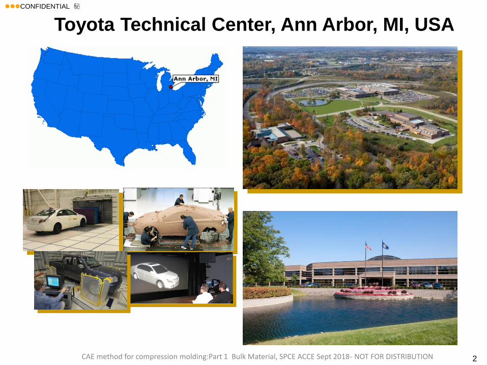
Toyota Technical Center, Ann Arbor, MI, USA
lllCONFIDENTIAL 秘
CAE method for compression molding:Part 1 Bulk Material, SPCE ACCE Sept 2018- NOT FOR DISTRIBUTION 3
Acknowledgement
We would like to thank, Takeshi Sekito, and
Hidetoshi Okada, Toyota Motor Company, Japan,
for their comments and valuable suggestions that
helped this project.
lllCONFIDENTIAL 秘
CAE method for compression molding:Part 1 Bulk Material, SPCE ACCE Sept 2018- NOT FOR DISTRIBUTION 4
Clarification for The Presentation
• This presentation is my opinion and views based on the industry and do not necessarily share Toyota’s view or future direction.
lllCONFIDENTIAL 秘
CAE method for compression molding:Part 1 Bulk Material, SPCE ACCE Sept 2018- NOT FOR DISTRIBUTION 5
1. Background and Motivation
2. Compression molding simulation for FRP
• Example 1
• Example 2
3. Conclusions
Agenda
lllCONFIDENTIAL 秘
CAE method for compression molding:Part 1 Bulk Material, SPCE ACCE Sept 2018- NOT FOR DISTRIBUTION6
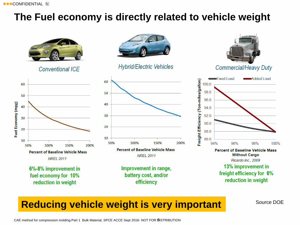
The Fuel economy is directly related to vehicle weight
Source DOEReducing vehicle weight is very important
lllCONFIDENTIAL 秘
CAE method for compression molding:Part 1 Bulk Material, SPCE ACCE Sept 2018- NOT
FOR DISTRIBUTION7
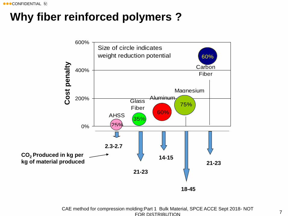
0%
200%
400%
600%
25%35%
60%
75%
60%
AHSS
Glass
Fiber
Aluminum
Magnesium
Carbon
Fiber
Size of circle indicates
weight reduction potential
C
o
s
t
P
e
n
a
l
t
y
CO2 Produced in kg per
kg of material produced
2.3-2.7
21-23
21-23
18-45
14-15
Co
st
pen
alt
y
Why fiber reinforced polymers ?
lllCONFIDENTIAL 秘
CAE method for compression molding:Part 1 Bulk Material, SPCE ACCE Sept 2018- NOT FOR DISTRIBUTION 8
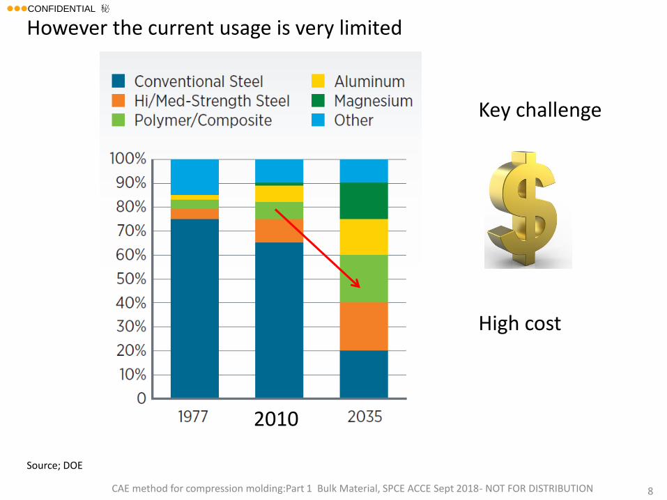
2010
Source; DOE
However the current usage is very limited
Key challenge
High cost
lllCONFIDENTIAL 秘
CAE method for compression molding:Part 1 Bulk Material, SPCE ACCE Sept 2018- NOT FOR DISTRIBUTION 9
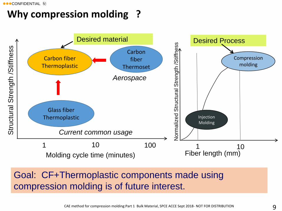
Why compression molding ?
Goal: CF+Thermoplastic components made using
compression molding is of future interest.
Molding cycle time (minutes)
100101
Str
uctu
ral S
trength
/S
tiffness
Carbon fiber
Thermoset
Glass fiber Thermoplastic
Carbon fiber Thermoplastic
Fiber length (mm)101
No
rma
lize
d S
tru
ctu
ral S
tre
ng
th /S
tiff
ness
Aerospace
Current common usage
Injection Molding
Compression molding
Desired material Desired Process
lllCONFIDENTIAL 秘
10
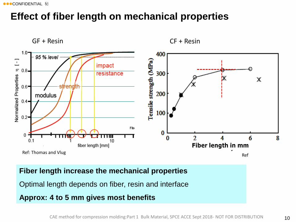
Fiber length increase the mechanical properties
Optimal length depends on fiber, resin and interface
Approx: 4 to 5 mm gives most benefits
Effect of fiber length on mechanical properties
CAE method for compression molding:Part 1 Bulk Material, SPCE ACCE Sept 2018- NOT FOR DISTRIBUTION
Ref: Thomas and Vlug
GF + Resin CF + Resin
Ref
lllCONFIDENTIAL 秘
CAE method for compression molding:Part 1 Bulk Material, SPCE ACCE Sept 2018- NOT FOR DISTRIBUTION 11
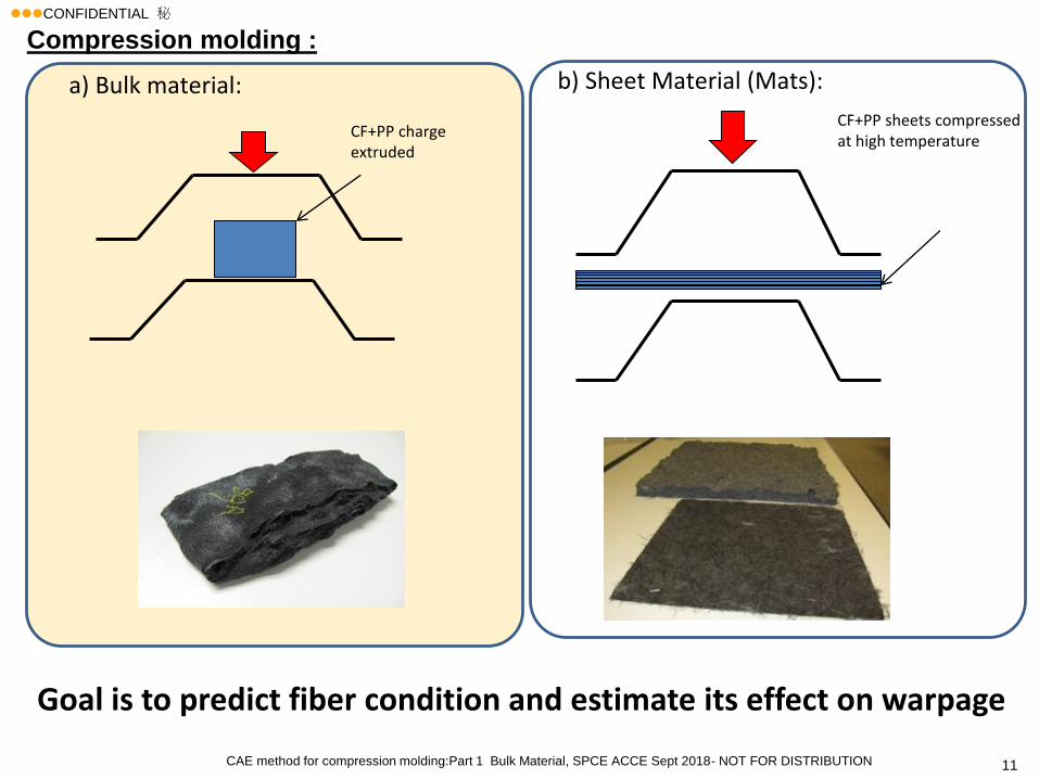
Compression molding :
CF+PP sheets compressed at high temperature
CF+PP charge extruded
a) Bulk material: b) Sheet Material (Mats):
Goal is to predict fiber condition and estimate its effect on warpage
lllCONFIDENTIAL 秘
CAE method for compression molding:Part 1 Bulk Material, SPCE ACCE Sept 2018- NOT FOR DISTRIBUTION 12
1. Background and Motivation
2. Compression molding simulation for FRP
• Example 1
• Example 2
3. Conclusions
Agenda
lllCONFIDENTIAL 秘
CAE method for compression molding:Part 1 Bulk Material, SPCE ACCE Sept 2018- NOT FOR DISTRIBUTION 13
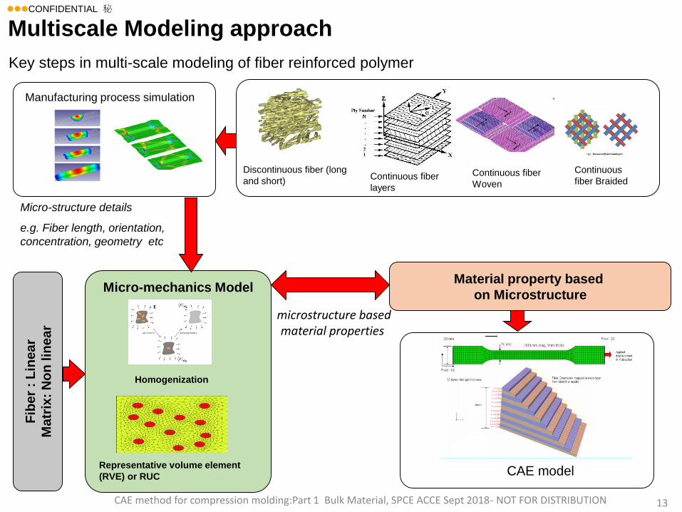
Micro-mechanics Model
microstructure based material properties
Micro-structure details
e.g. Fiber length, orientation,
concentration, geometry etc
Key steps in multi-scale modeling of fiber reinforced polymer
Homogenization
Representative volume element
(RVE) or RUC CAE model
Material property based
on Microstructure
Discontinuous fiber (long
and short)
Manufacturing process simulation
Fib
er
: L
inear
Ma
trix
: N
on
lin
ea
r
Continuous fiber
layers
Continuous fiber
Woven
Continuous
fiber Braided
Multiscale Modeling approach
lllCONFIDENTIAL 秘
CAE method for compression molding:Part 1 Bulk Material, SPCE ACCE Sept 2018- NOT FOR DISTRIBUTION 14
EXAMPLE 1
lllCONFIDENTIAL 秘
CAE method for compression molding:Part 1 Bulk Material, SPCE ACCE Sept 2018- NOT FOR DISTRIBUTION 15
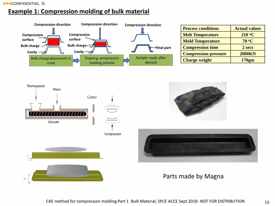
Process conditions Actual values
Melt Temperature 210 oC
Mold Temperature 70 oC
Compression time 2 secs
Compression pressure 2000KN
Charge weight 170gm
Example 1: Compression molding of bulk material
Parts made by Magna
lllCONFIDENTIAL 秘
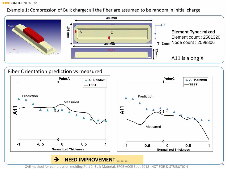
480mm
32m
m
480mm
101 m
m
T=2mm
Element Type: mixed
Element count : 2501320
Node count : 2598806
A C
Example 1: Compression of Bulk charge: all the fiber are assumed to be random in initial charge
Prediction
Measured
Measured
Prediction
CAE method for compression molding:Part 1 Bulk Material, SPCE ACCE Sept 2018- NOT FOR DISTRIBUTION16
A11 is along X
Fiber Orientation prediction vs measured
NEED IMPROVEMENT ………
lllCONFIDENTIAL 秘
CAE method for compression molding:Part 1 Bulk Material, SPCE ACCE Sept 2018- NOT FOR DISTRIBUTION17
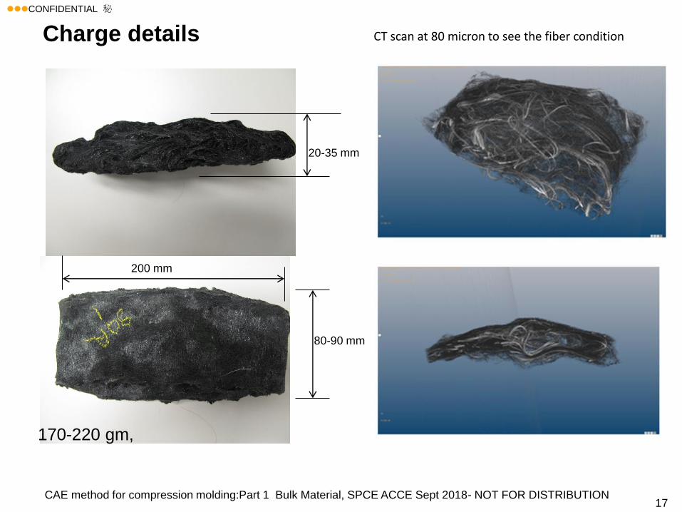
Charge details
80-90 mm
200 mm
20-35 mm
170-220 gm,
CT scan at 80 micron to see the fiber condition
lllCONFIDENTIAL 秘
CAE method for compression molding:Part 1 Bulk Material, SPCE ACCE Sept 2018- NOT FOR DISTRIBUTION 18
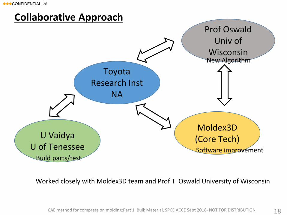
Toyota Research Inst
NA
Moldex3D(Core Tech)
Prof OswaldUniv of
Wisconsin
Worked closely with Moldex3D team and Prof T. Oswald University of Wisconsin
Collaborative Approach
U VaidyaU of Tenessee
Build parts/testSoftware improvement
New Algorithm
lllCONFIDENTIAL 秘
CAE method for compression molding:Part 1 Bulk Material, SPCE ACCE Sept 2018- NOT FOR DISTRIBUTION 19
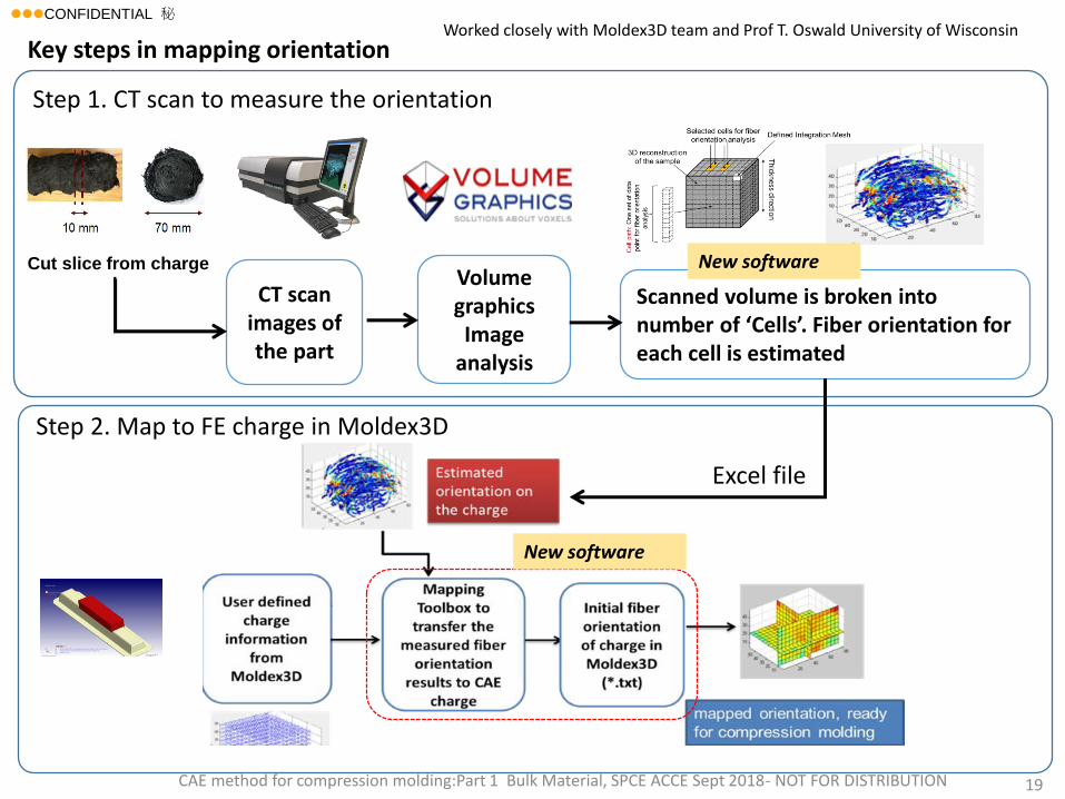
Worked closely with Moldex3D team and Prof T. Oswald University of Wisconsin
Volume graphicsImage
analysis
CT scan images of the part
Scanned volume is broken into number of ‘Cells’. Fiber orientation for each cell is estimated
Cut slice from charge
Key steps in mapping orientation
Step 1. CT scan to measure the orientation
Excel file
New software
New software
Step 2. Map to FE charge in Moldex3D
lllCONFIDENTIAL 秘
CAE method for compression molding:Part 1 Bulk Material, SPCE ACCE Sept 2018- NOT FOR DISTRIBUTION 20
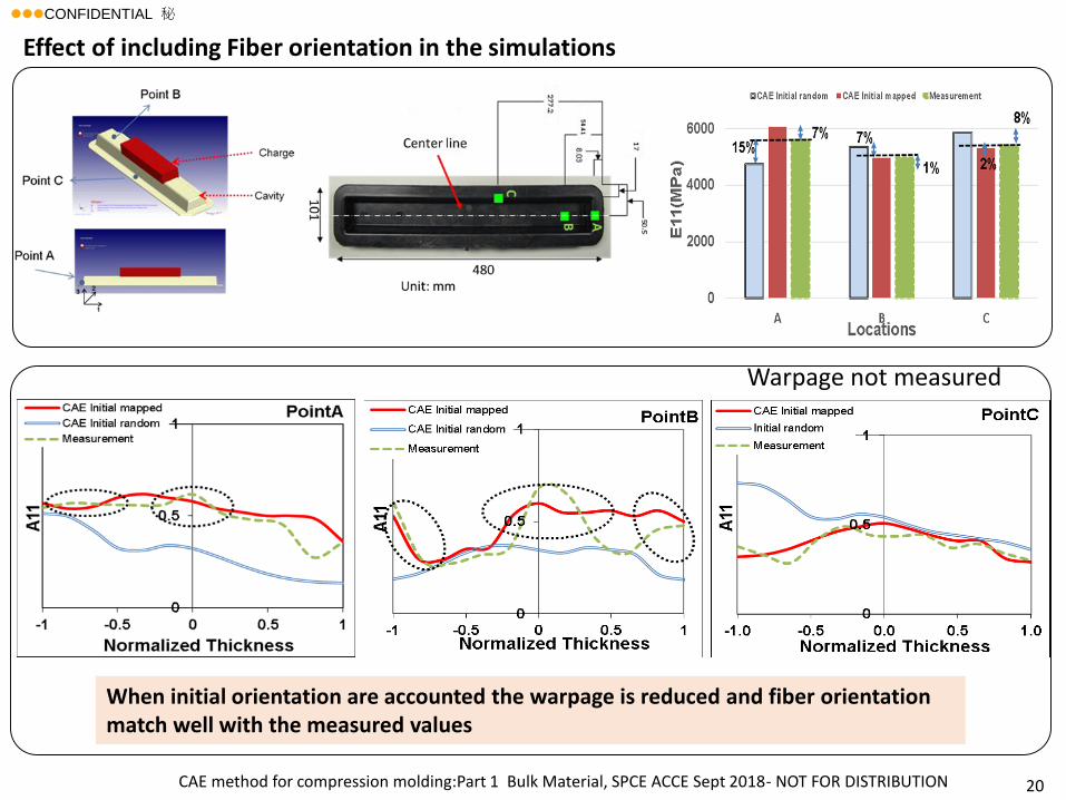
When initial orientation are accounted the warpage is reduced and fiber orientation match well with the measured values
Effect of including Fiber orientation in the simulations
Warpage not measured
lllCONFIDENTIAL 秘
CAE method for compression molding:Part 1 Bulk Material, SPCE ACCE Sept 2018- NOT FOR DISTRIBUTION 21
EXAMPLE 2
lllCONFIDENTIAL 秘
CAE method for compression molding:Part 1 Bulk Material, SPCE ACCE Sept 2018- NOT FOR DISTRIBUTION22
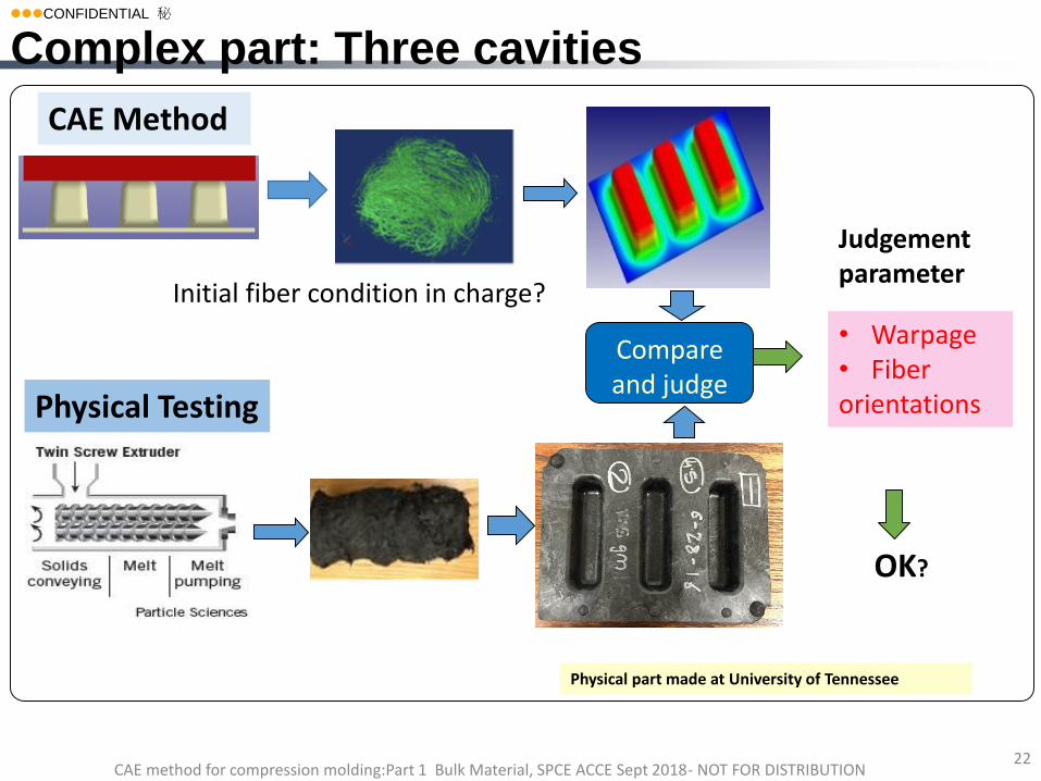
Complex part: Three cavities
• Warpage• Fiber orientations
Compare and judge
OK?
Judgement parameter
CAE Method
Physical Testing
Physical part made at University of Tennessee
Initial fiber condition in charge?
lllCONFIDENTIAL 秘
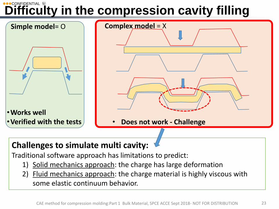
Challenges to simulate multi cavity:Traditional software approach has limitations to predict:
1) Solid mechanics approach: the charge has large deformation2) Fluid mechanics approach: the charge material is highly viscous with
some elastic continuum behavior.
23
2
•Works well•Verified with the tests • Does not work - Challenge
Simple model= O Complex model = X
Difficulty in the compression cavity filling
CAE method for compression molding:Part 1 Bulk Material, SPCE ACCE Sept 2018- NOT FOR DISTRIBUTION
lllCONFIDENTIAL 秘
24
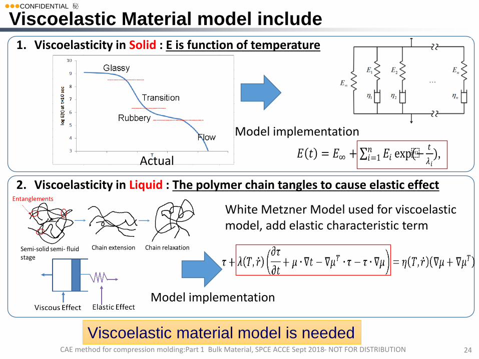
1. Viscoelasticity in Solid : E is function of temperature
Actual
Model implementation
2. Viscoelasticity in Liquid : The polymer chain tangles to cause elastic effect
Viscoelastic Material model include
CAE method for compression molding:Part 1 Bulk Material, SPCE ACCE Sept 2018- NOT FOR DISTRIBUTION
𝐸 𝑡 = 𝐸∞ + 𝐸𝑖𝑛𝑖=1 exp(−
𝑡
𝜆𝑖),
Model implementation
Viscoelastic material model is needed
White Metzner Model used for viscoelastic model, add elastic characteristic term
lllCONFIDENTIAL 秘
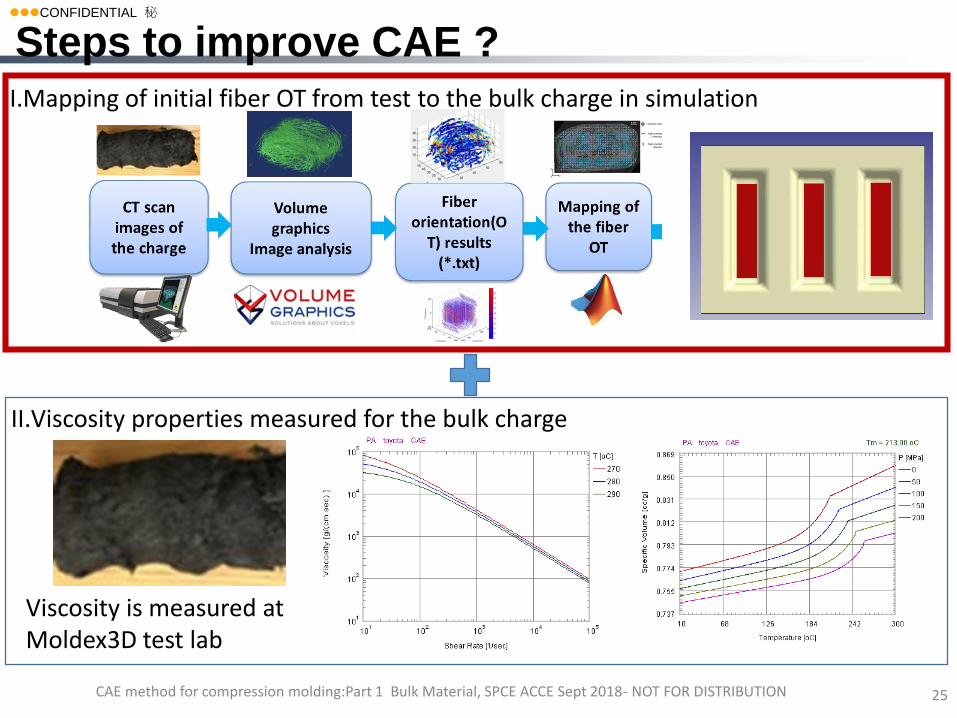
I.Mapping of initial fiber OT from test to the bulk charge in simulation
II.Viscosity properties measured for the bulk charge
25
Viscosity is measured at Moldex3D test lab
Steps to improve CAE ?
CAE method for compression molding:Part 1 Bulk Material, SPCE ACCE Sept 2018- NOT FOR DISTRIBUTION
lllCONFIDENTIAL 秘
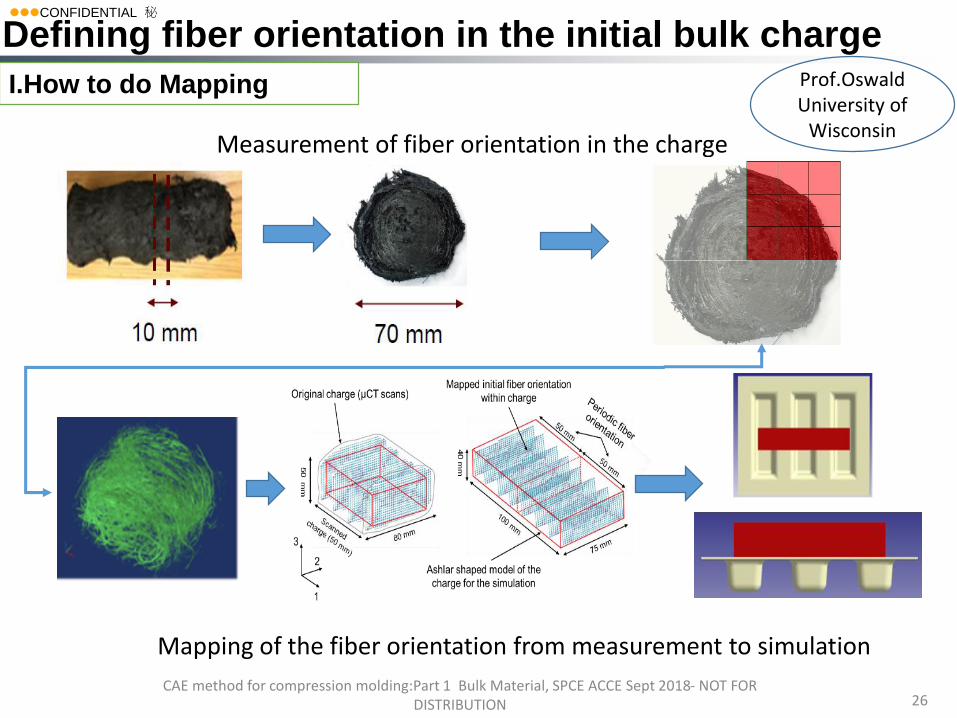
I.How to do Mapping
26
Measurement of fiber orientation in the charge
Mapping of the fiber orientation from measurement to simulation
Defining fiber orientation in the initial bulk charge
CAE method for compression molding:Part 1 Bulk Material, SPCE ACCE Sept 2018- NOT FOR DISTRIBUTION
Prof.OswaldUniversity of
Wisconsin
lllCONFIDENTIAL 秘
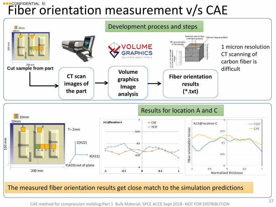
Fiber orientation measurement v/s CAE
Volume graphicsImage
analysis
CT scan images of the part
Fiber orientation results(*.txt)
Cut sample from part
The measured fiber orientation results get close match to the simulation predictions
27
1 micron resolution CT scanning of carbon fiber is difficult
Development process and steps
Results for location A and C
CAE method for compression molding:Part 1 Bulk Material, SPCE ACCE Sept 2018- NOT FOR DISTRIBUTION
lllCONFIDENTIAL 秘
28
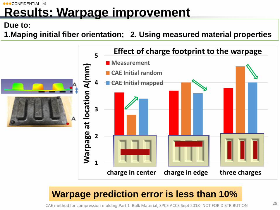
Results: Warpage improvement
CAE method for compression molding:Part 1 Bulk Material, SPCE ACCE Sept 2018- NOT FOR DISTRIBUTION
Due to:
1.Maping initial fiber orientation; 2. Using measured material properties
Warpage prediction error is less than 10%
lllCONFIDENTIAL 秘
CAE method for compression molding:Part 1 Bulk Material, SPCE ACCE Sept 2018- NOT FOR DISTRIBUTION 29
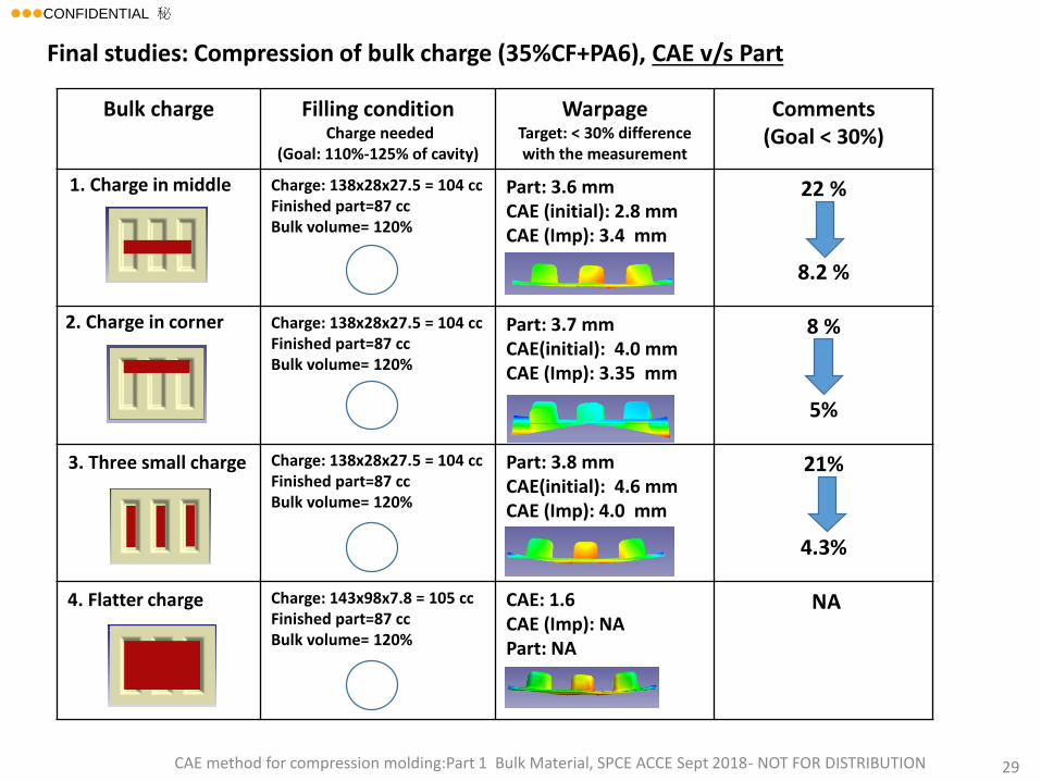
Bulk charge Filling conditionCharge needed
(Goal: 110%-125% of cavity)
Warpage Target: < 30% difference with the measurement
Comments(Goal < 30%)
Charge: 138x28x27.5 = 104 ccFinished part=87 cc Bulk volume= 120%
Part: 3.6 mmCAE (initial): 2.8 mmCAE (Imp): 3.4 mm
22 %
8.2 %
Charge: 138x28x27.5 = 104 ccFinished part=87 cc Bulk volume= 120%
Part: 3.7 mmCAE(initial): 4.0 mmCAE (Imp): 3.35 mm
8 %
5%
Charge: 138x28x27.5 = 104 cc Finished part=87 cc Bulk volume= 120%
Part: 3.8 mmCAE(initial): 4.6 mmCAE (Imp): 4.0 mm
21%
4.3%
4. Flatter charge Charge: 143x98x7.8 = 105 ccFinished part=87 cc Bulk volume= 120%
CAE: 1.6 CAE (Imp): NAPart: NA
NA
1. Charge in middle
3. Three small charge
2. Charge in corner
Final studies: Compression of bulk charge (35%CF+PA6), CAE v/s Part
lllCONFIDENTIAL 秘
CAE method for compression molding:Part 1 Bulk Material, SPCE ACCE Sept 2018- NOT FOR DISTRIBUTION 30
1. Background and Motivation
2. Compression molding simulation for FRP
• Example 1
• Example 2
3. Conclusions
Agenda
lllCONFIDENTIAL 秘
CAE method for compression molding:Part 1 Bulk Material, SPCE ACCE Sept 2018- NOT FOR DISTRIBUTION 31
3 Conclusions
a) Compression molding can help achieve lightweight structural
parts for automotive applications.
b) Moldex3D offers CAE-tool to study compression molding of
complex 3D parts.
c) Method to define initial orientation of the fibers in the charge is
developed.
d) It is important to treat material as viscoelastic during the
compression filling process.
c) We have used Moldex3D successfully to predict the fiber
orientation and warpage in the compression molding of fiber
reinforced thermoplastic example parts.
d) The results are verified with measured data for two examples.