Embed Size (px)
Citation preview

CAFE Series Airpot/ Thermal DecanterPourover Coffee Brewing System
USER GUIDE
READ AND SAVE THESE INSTRUCTIONS NOTICE TO INSTALLER: Please leave this booklet with the machine.

CONTENTS CL36
..............................................................................................FS36
............................................................................................................................................... IS2
...............................................................................................................................II4
..............................................................................................................II5
............................................................................................................................................OI29
...............................................................................................................................CI1
............................................................................................................CI9
...........................................................................................................................CI12
.............................................................................................................................................
.................................................................................................................................................
................................................................................................................... IP65
....................................................................... IP66
........................................................................... IP67
............................................................................................................................ES68
................................................................................................................................ES69
..........................................................................................................................................
....................................................................................................................................................
Contact Information
Wilbur Curtis Co., Inc.6913 Acco Street | Montebello, CA 90640 US
Phone: 323-837-2300 | Toll Free: 800-421-6150Email: [email protected] | Web: www.wilburcurtis.com
A.M. - 4:00 P.M. PTEmail: [email protected]

KEY FEATURES/SPECIFICATIONS/SYSTEM REQUIREMENTS FS36
Key Features
• Pourover operation – No plumbing required.
• Powerful heating element provides quick recovery for faster brewing.
• Large-volume water tank for greater brewing capacity.
• Space-saving design.
• Stainless steel construction with textured black powder coating.
Pourover Airpot Brewer 1 PH 120 V 12.1 A 1 x 1450 W 2W + G 1450 W 50/60 Hz 4.2
Pourover Pourpot Brewer 1 PH 120 V 12.1 A 1 x 1450 W 2W + G 1450 W 50/60 Hz 4.2
Pourover Airpot Brewer, Export 1 PH 230 V 9.5 A 1 x 2000 W 2W + G 2185 W 50/60 Hz 6.0
Pourover Pourpot Brewer, Export 1 PH 230 V 9.5 A 1 x 2000 W 2W + G 2185 W 50/60 Hz 6.0
24.88” 9.25” 17.88” 31.0 lbs 5.60 cu ft
17.63” 9.25” 17.88” 23.0 lbs 3.92 cu ft
24.88” 9.25” 19.00” 31.0 lbs 5.60 cu ft
17.63” 9.25” 19.00” 23.0 lbs 3.92 cu ft
CAFE AIRPOT/THERMAL DECANTER BREWER, KEY FEATURES/SPECS/SYSTEM REQUIREMENTS 101817NC

IMPORTANT SAFEGUARDS IS2
Symbols
This is the safety alert symbol. It is used to alert you to potential physical injury hazards. Obey all safety messages that follow this symbol to avoid possible injury or death.
DANGER - Indicates a hazardous situation which, if not avoided, will result in death or serious injury.
WARNING - Indicates a hazardous situation which, if not avoided, could result in death or serious injury.
CAUTION - Indicates a hazardous situation which, if not avoided, could result in minor or moderate injury.
NOTICE - Indicates a situation which, if not avoided, could result in property damage.
IMPORTANT - Provides information and tips for proper operation.
SANITATION REQUIREMENTS
Important Safeguards/Conventions
WARNING:
• Make sure that this appliance is installed and grounded according to the INSTALLATION
INSTRUCTIONS could result in personal injury or void the warranty.
• This appliance is designed for commercial use. Any service other than cleaning and preventive
maintenance should be performed by an authorized Wilbur Curtis service technician.
•
serviceable parts inside.
• Keep hands, arms and other items away from hot surfaces of the unit during operation.
• Clean the appliance and any dispensers completely
the CLEANING INSTRUCTIONS. Clean them regularly as instructed in the CLEANING INSTRUCTIONS.
• Use this appliance only for its intended use, brewing/dispensing hot and/or cold beverages/water.
• This appliance is not intended for use by persons (including children) with reduced physical, sensory
or mental capabilities or lack of experience and knowledge, unless they have been given supervision
or instruction concerning use of the appliance by a person responsible for their safety.
• Children should be supervised to ensure that they do not play with the appliance.
• Avoid spillage onto the power (mains) connector.

IMPORTANT SAFEGUARDS IS2
CE Requirements
• This appliance must be installed in locations where it can be overseen by trained personnel.
•
•
•
• This appliance must not be cleaned by water jet.
• instruction concerning use of the appliance in a safe way and if they understand the hazards involved.
•
• or lack of experience and knowledge if they have been given supervision or instruction concerning use of the appliance in a safe way and understand the hazards involved.
•
• If the power cord is ever damaged, it must be replaced by the manufacturer or authorized service personnel with a special cord available from the manufacturer or its authorized service personnel in order to avoid a hazard.
• Machine must not be immersed for cleaning.
• supervised.
• This appliance is intended to be used in household and similar applications such as:
– bed and breakfast type environments.
• This appliance not intended to be used in applications such as:
– farm houses
• Access to the service areas permitted by Authorized Service personnel only.
•

INSTALLATION INSTRUCTIONS II4
Installation Instructions
Installation Requirements
• A secure surface capable of supporting the weight of the appliance.
• For appliances without an attached cord set: Appropriately sized, UL listed, grounding type power cable to
long enough
• appliance (see SPECIFICATIONS). The circuit must be protected by the appropriate sized circuit breaker.
electrician.
WARNING:properly grounded.
WARNING:
IMPORTANT:

Installation
Leveling
1 Position the brewer on the countertop near an electrical outlet that meets the SPECIFICATIONS. Level the brewer left to right and front to back by turning the bottom of the legs.
Connecting the Brewer Power Plug - Export Units
2 Connect the appropriate type of grounded power plug to the end of the power cord coming from the back of the unit.
INSTALLATION INSTRUCTIONS II5
CAFE, INSTALLATION INSTRUCTIONS 100917NC
WARNING: Use the leveling legs to level the brewer only. Do not use them to adjust brewer height. Do not extend them higher than necessary.
NOTICE - This brewer is shipped with the thermostat turned ON. DO NOT plug in the brewer before pouring 3 pots/192 oz. of water into the opening as instructed below; damage to the heating element and/or thermostat will result.
Prepare the Brewer for Use
3 Place an empty glass decanter on the warmer deck, under the spray head.
4 Insert the empty brew basket into the brew rails of the brewer, below the control panel.
5 Fill the water tank by slowly pouring room temperature water through the opening on the top cover, until water starts running in a steady stream from the brew basket. It takes approximately three pots or 192
of the brew basket.

INSTALLATION INSTRUCTIONS II5
CAFE, INSTALLATION INSTRUCTIONS 100917NC
Powering Up the Brewer
6 Connect the power cord to the electrical outlet.
7 Make sure that the circuit breaker supplying power to the brewer is on.
8 On brewers equipped with a toggle switch on the back, turn the toggle switch to the ON position.
9 Depending on the water temperature and the electrical
minutes to reach operating temperature. When the water has heated, READY TO BREW light will come on.
WARNING: Connect the power cords only to the appropriate type and size electrical outlet. If the electrical outlet is not compatible with the power cords, have it upgraded by a licensed electrician. Do not modify the power plug. Do not use an extension cord. Do not use a power cord/plug that is damaged.
IMPORTANT: When operating the brewer at elevations higher than 2000 feet (600 meters), have
unit. See the PROGRAMMING GUIDE section.

WARNING - TO AVOID SCALDING, AVOID SPLASHING. The brew basket contains hot coffee grounds. Keep body parts clear of the brewer during brewing. Allow the brew basket to drain before removing it. Be
OPERATING INSTRUCTIONS OI29
Brewing Instructions
2 Center an empty airpot or thermal decanter under the brew basket.
3 the brew basket.
4 Fill the brew basket with the proper amount of ground coffee. Level the coffee in the
5 into the brew rails under the control panel. Slide it all the way back until it stops.
The brewer should be plugged in and the “READY TO BREW" light should be lit. On units with a rear toggle switch, make sure it is in the ON position.
6 Using a pitcher, pour room temperature water into the pourover opening on the top.
will be about three minutes.
NOTICE - INSTALLATION INSTRUCTIONS section. Connecting the power without a full water tank will damage the brewer.
Before Brewing:
• A pitcher with a volume less than or equal to the volume of the airpot/thermal dispenser is required for brewing.
• Some water in the water tank may evaporate if the brewer is left on for long periods of time. When this occurs,

NOTICE - Do not use cleaning liquids, compounds or powders containing chlorine (bleach) or corrosives. USE OF THESE PRODUCTS WILL VOID
THE WARRANTY.
CLEANING INSTRUCTIONS CI1
Cleaning The Brewer - Daily
BREWERS - GENERIC, CLEANING INSTRUCTIONS 080416B
WARNING: HOT SURFACES - To avoid injury, allow the brewer and dispenser(s) to cool before cleaning.
The brewer should be OFF.
1 Remove the dispenser(s). Wipe exterior brewer surfaces with a damp cloth to remove spills and debris.
2 Remove the brew basket(s) and clean them in a mild detergent solution. Use a soft bristled brush for hard to clean areas. Rinse with clean water, then dry.
3 Wipe the spray head area with a cloth soaked in a mild detergent solution. Rinse with a cloth soaked with clean water removing any residual detergent. Use a clean, soft cloth to dry.
4 Dump out the drip tray(s) (if applicable). Rinse with clean water, then dry with a soft, clean cloth.
Cleaning The Brewer - Weekly
The brewer should be OFF.
1 Remove the spray head(s), unscrewing counterclockwise from the dome plate.
2 Thoroughly clean and rinse the dome plate area.
3 Clean the brew basket rails with a brush soaked with a mild detergent solution. Rinse the area with a cloth soaked with clean water, removing any residual detergent.
4 Dry the area with a soft, clean cloth.
5 Reattach the spray head(s).
WARNING: DO NOT immerse the brewer in water or any other liquid.

Cleaning the Airpot/Pour Pot (Daily)
CLEANING INSTRUCTIONS CI9
WARNING: DO NOT immerse the airpot/pour pot or lid assembly in water or any other liquid. Do not place the airpot/pour pot or lid in a dishwasher. Placing a airpot or pour pot in a dishwasher will void the warranty.
Cleaning Airpots
Wash - Wipe the exterior surfaces of the airpot and lid with a sponge soaked with the detergent solution to remove spills and debris. Fill the liner with the detergent solution. Use a sponge cleaning brush to clean inside. Clean the spout/siphon tube with the detergent solution.
2 Rinse - Rinse the airpot and the spout/siphon tube with clean, warm water.
Sanitize - Sanitize the interior of the airpot, the spout/siphon tube and the lid, using a commercial sanitizer suitable for food grade applications. Swab, brush or pressure spray the sanitizing solution according to the directions on the package.
4 Air Dry - Turn the airpot and lid upside down. Allow all parts to air dry.
Cleaning Pour Pots
Wash - Wipe the exterior surfaces of the pour pot and lid with a sponge soaked with the detergent solution to remove spills and debris. Fill the liner with the detergent solution. Use a sponge cleaning brush to clean inside.
2 Rinse - Rinse the pour pot and the lid with clean, warm water.
Sanitize - Sanitize the interior of the pour pot and the lid, using a commercial sanitizer suitable for food grade applications. Swab, brush or pressure spray the sanitizing solution according to the directions on the package.
4 Air Dry - Turn the pour pot and lid upside down and allow to air dry.
Start by preparing a mild solution of detergent and warm water. Remove the airpot/pour pot from the brewer and remove/open the lid. On airpots, remove the nozzle assembly. Rinse.
Nozzleassembly
TLXA2201G000 shown. Appearance and size varies with model number.
CLXP6401S100 shown. Appearance and size varies with model number.
NOTE: The stem on the bottom of TFT series pour pot lids have a built-in sensor used for the FreshTrac feature. Keep this stem free from coffee oil build-up for proper operation. After cleaning, inverting the lid

CLEANING INSTRUCTIONS CI12
De-liming Procedure*
NOTICE -
2

Electronic Thermostat
The electronic thermostat has two settings; 200°F (93°C) and 190°F (88°C). The factory default setting is 200°F. If operating the brewer at altitudes higher than 2000 feet (600 m), set it to 190°F.
1 Unplug the brewer power cord.
2 Remove the back cover.
3 Locate the thermostat, attached to a bracket near the top of the compartment.
4 Locate the temperature setting jumper pins. It is labeled “200°F” on the printed circuit board.
5 When jumpered, the board is set to 200ºF. When the jumper is removed, it is set to 190ºF. When setting the thermostat to 190ºF, slip the jumper over (only) one of the pins, in the event that the board needs to be changed back.
6 Replace the back cover and reconnect power. continued....
Thermostat Adjustment
The brewer is equipped with either an electronic or mechanical (capillary) type thermostat. The tank temperature (thermostat) adjustment procedure is different for each type.
PROGRAMMING GUIDE PG11
WARNING -
Electronic Thermostat Mechanical Thermostat
Jumper in 200°F position
(default)
Jumper in 190°F position
Remove jumper to change
setting

PROGRAMMING GUIDE PG11
Mechanical Thermostat
The mechanical thermostat has an adjustment screw used to set the temperature. The factory default setting is 200°F (93°C). When operating the brewer at higher elevations, reduce the operating temperature by 2°F for each 1000 feet of elevation.
1 Unplug the brewer power cord.
2 Remove the top cover.
3 Locate the thermostat, attached to a bracket near the back of the compartment.
4
When the screw is turned all the way clockwise, the thermostat is set to 200°F.
5 Replace the back cover and reconnect power.
6 If the brew temperature of the water is too cool, readjust following the above steps, keeping in mind that too high a temperature setting at higher altitudes may cause the water in the tank to boil.
Adjustmentscrew

ROUGH-IN DRAWINGS RD42
CAFE0AP Series Coffee Brewers
CAFE AIRPOT/THERMAL DECANTER BREWER, ROUGH-IN DRAWING 112316NC
* Units equipped with a toggle switch only
24.88 in[63.2 cm ]
24.5 in[62.2 cm ]
17.88 in[45.4 cm ]
19.00 in*[48.3 cm ]
9.25 in[23.5 cm ]
ROUGH-IN DRAWINGS RD42
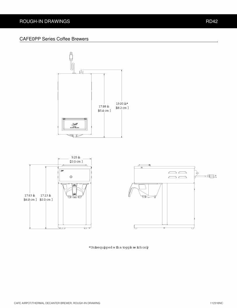
CAFE0PP Series Coffee Brewers
CAFE AIRPOT/THERMAL DECANTER BREWER, ROUGH-IN DRAWING 112316NC
* Units equipped with a toggle switch only
17.63 in[44.8 cm ]
17.13 in[43.5 cm ]
17.88 in[45.4 cm ]
19.00 in*[48.3 cm ]
9.25 in[23.5 cm ]

ILLUSTRATED PARTS LIST IP64
CAFE GLASS DECANTER BREWER, ILLUSTRATED PARTS/RECOMMENDED PARTS 101117NC
Supplies and Accessories - All Models
CAB-1 - Cleaning BrushWC-29025 - Spray Head
10
11
6
9
17
13
7A
7B
16
14
4
3
5
8
12A12B
2A2B
15A15B
1
CAFE0AP, CAFE0PP - Main Chassis - Exploded View
Water tank assemblies:- Domestic, see section IP66- Export, see section IP67

ILLUSTRATED PARTS LIST IP64
CAFE GLASS DECANTER BREWER, ILLUSTRATED PARTS/RECOMMENDED PARTS 101117NC
ITEM # PART # DESCRIPTION
1 WC-54121 PAN, POUR CAFÉ
2A WC-207 1,3 LIGHT, BREW 115V GREEN
2B WC-208 2,4 LIGHT, BREW 250V GREEN
3 WC-3502 LEG, 8-32 STUD SCREW BUMPER
4 WC-3645SPRING, DELIMING .041 X 20” GALVANIZED WIRE HARD DRAWN
5 WC-54118 TRAY, ASSY CAFE POUR OVER
6 WC-4213 NUT, 5/8 LOCK PLATED
7A WC-735-101 1,3 THERMOSTAT, TEMPERATURE CONTROL 120VAC POUROVER CAFE
7B WC-504 2,4 THERMOSTAT, CAPILLARY SPST 250V 25A GEM
8 WC-39371 LABEL, SW PANEL CAFÉ AP CURTIS
9 WC-29025 SPRAYHEAD, PURPLE ADVANCE FLOW
ITEM # PART # DESCRIPTION
10 WC-29054 TUBE, W/A CAFE POUR OVERS
11 WC-3621-101BREW CONE, NON-METAL UNIVERSAL (WITH SPLASH POCKET)
12A WC-13301-101 1,3 HARNESS ASSY, CAFE AP 120V FOR ELECTRONIC THERMOSTAT
12B WC-13301 2,4 HARNESS ASSY, CAFÉ AP 220V
13 WC-5310 TUBE, 5/16 ID x 1/8W SILICONE GEN USE
14 WC-1408 CORD GRIP, 7/8” O.D.
15A WC-1200 1,3 CORD, 14/3 SJTO 6’ BLK W/PLUG
15B WC-1231-103 2,4 CORD, 2.5 mm² PRE-CUT W/ CONNECTORS
16 WC-103 2,4 SWITCH, TOGGLE NON-LIT DPST 25A 125/250VAC RESISTIVE
17 WC-5231 COMPOUND, SILICONE 5 OZ
CAFE0AP, CAFE0PP - Main Chassis - Parts List
1 CAFE0AP10A000, 2 CAFE0AP30A000, 3 CAFE0PP10A000, 4 CAFE0PP30A000
ITEM # PART # DESCRIPTION
9 WC-29025 SPRAYHEAD, PURPLE ADVANCE FLOW
13 WC-5310 TUBE, 5/16 ID x 1/8W SILICONE GEN USE
16 WC-103SWITCH, TOGGLE NON-LIT DPST 25A 125/250VAC RESISTIVE
ITEM # PART # DESCRIPTION
17 WC-5231 COMPOUND, SILICONE 5 OZ
CAFE0AP, CAFE0PP - Main Chassis - Recommended Parts to Stock

ILLUSTRATED PARTS/RECOMMENDED PARTS IP66
ITEM # PART # DESCRIPTION
1 WC-54117 TANK, COMPLETE 1450W 120V CAFÉ
2 WC-54125-101 COVER, W/A HEATING TANK CAFE
3 WC-43062 GASKET, TANK LID
4 WC-5418 CLIP, RESET THERMOSTAT GEN USE
5 WC-917-04ELEMENT, HEATING 1.45KW 120V W/JAM NUTS & SILICONE O-RING
6 WC-1438-101 SENSOR, TEMPERATURE TANK
7 WC-4394GUARD, SHOCK/HEATING ELEMENT FOR SINGLE HEATING ELEMENT
ITEM # PART # DESCRIPTION
3 WC-43062 GASKET, TANK LID
5 WC-917-04ELEMENT, HEATING 1.45KW 120V W/JAM NUTS & SILICONE O-RING
6 WC-1438-101 SENSOR, TEMPERATURE TANK
7 WC-4394GUARD, SHOCK/HEATING ELEMENT FOR SINGLE HEATING ELEMENT
WC-54117 - Recommended Parts to Stock
ITEM # PART # DESCRIPTION
8 WC-521THERMOSTAT, HI-LIMIT SPST 120V 15A AUTO-RE-SET
9 WC-2627BUSHING, CONICAL .583ID X .945 OD .886LG 12mm GEN USE
10 WC-2628BUSHING, CONICAL.469 ID X .945 OD X .986 LG 8mm GEN USE
ITEM # PART # DESCRIPTION
8 WC-521THERMOSTAT, HI-LIMIT SPST 120V 15A AUTO-RE-SET
9 WC-2627BUSHING, CONICAL .583ID X .945 OD .886LG 12mm GEN USE
10 WC-2628BUSHING, CONICAL.469 ID X .945 OD X .986 LG 8mm GEN USE
11 WC-29042 HOSE, VENTILATION HEATING TANK CAFÉ
WC-54117 - Tank Assembly
2
3
6
7
4
8
1
5
9
WC-54117 - Tank Assembly - Parts List
11
10
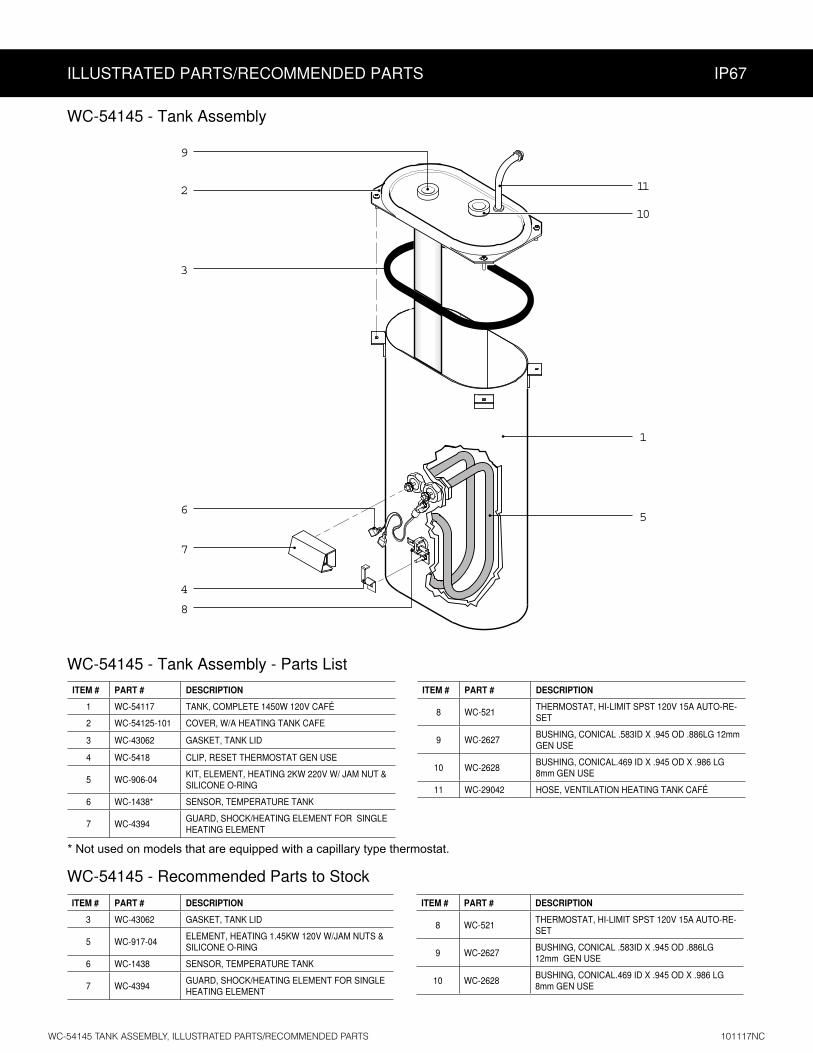
ILLUSTRATED PARTS/RECOMMENDED PARTS IP67
ITEM # PART # DESCRIPTION
1 WC-54117 TANK, COMPLETE 1450W 120V CAFÉ
2 WC-54125-101 COVER, W/A HEATING TANK CAFE
3 WC-43062 GASKET, TANK LID
4 WC-5418 CLIP, RESET THERMOSTAT GEN USE
5 WC-906-04KIT, ELEMENT, HEATING 2KW 220V W/ JAM NUT & SILICONE O-RING
6 WC-1438* SENSOR, TEMPERATURE TANK
7 WC-4394GUARD, SHOCK/HEATING ELEMENT FOR SINGLE HEATING ELEMENT
ITEM # PART # DESCRIPTION
3 WC-43062 GASKET, TANK LID
5 WC-917-04ELEMENT, HEATING 1.45KW 120V W/JAM NUTS & SILICONE O-RING
6 WC-1438 SENSOR, TEMPERATURE TANK
7 WC-4394GUARD, SHOCK/HEATING ELEMENT FOR SINGLE HEATING ELEMENT
WC-54145 - Recommended Parts to Stock
ITEM # PART # DESCRIPTION
8 WC-521THERMOSTAT, HI-LIMIT SPST 120V 15A AUTO-RE-SET
9 WC-2627BUSHING, CONICAL .583ID X .945 OD .886LG 12mm GEN USE
10 WC-2628BUSHING, CONICAL.469 ID X .945 OD X .986 LG 8mm GEN USE
ITEM # PART # DESCRIPTION
8 WC-521THERMOSTAT, HI-LIMIT SPST 120V 15A AUTO-RE-SET
9 WC-2627BUSHING, CONICAL .583ID X .945 OD .886LG 12mm GEN USE
10 WC-2628BUSHING, CONICAL.469 ID X .945 OD X .986 LG 8mm GEN USE
11 WC-29042 HOSE, VENTILATION HEATING TANK CAFÉ
WC-54145 - Tank Assembly
2
3
6
7
4
8
1
5
9
WC-54145 - Tank Assembly - Parts List
11
10
* Not used on models that are equipped with a capillary type thermostat.
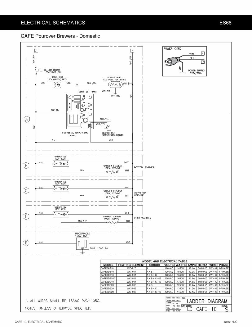
ELECTRICAL SCHEMATICS ES68
MODEL HEATING ELEMENT CIRCUIT VOLTS WATTS AMPS HERTZ WIRE PHASECAFE0AP10 WC-917 A 120VAC 1450W 12.1A 50/60HZ 2W + G 1-PHASECAFE1DB10 WC- 917 A + B 120VAC 1550W 12.9A 50/60HZ 2W + G 1-PHASECAFE2DB10 WC- 917 A + B + C 120VAC 1650W 13.8A 50/60HZ 2W + G 1-PHASECAFE2DBS10 WC- 917 A + B + C + E 120VAC 1650W 13.8A 50/60HZ 2W + G 1-PHASECAFE3DB10 WC- 917 A + B + C + D 120VAC 1750W 14.6A 50/60HZ 2W + G 1-PHASECAFE1DB20 WC- 933 A + B 120VAC 1250W 10.4A 50/60HZ 2W + G 1-PHASECAFE2DB20 WC- 933 A + B + C 120VAC 1350W 11.3A 50/60HZ 2W + G 1-PHASECAFE3DB20 WC- 933 A + B + C + D 120VAC 1450W 12.1A 50/60HZ 2W + G 1-PHASE
MODEL AND ELECTRICAL TABLE
CAFE Pourover Brewers - Domestic

ELECTRICAL SCHEMATICS ES69
ModelVoltage
VAmps
AWa s
WHertz
Hz
# of Conductor
WiresPhase
# of Tank Elements
Tank Element Ra ng W/V
Warmer Element Ra ng W/V
CAFE0AP30AxCAFE0PP30AxCAFE1DB30Ax
06890A03BD1EFAC06/05xA03BD2EFAC
06890A03BD2EFAC06/05xA03BD3EFAC
06890A03BD3EFACCAFE0AP30AxCAFE0PP30AxCAFE1DB30Ax
06890A03BD1EFAC06/05xA03BD2EFAC
06890A03BD2EFAC06/05xA03BD3EFAC
06890A03BD3EFACCAFE0AP30AxCAFE0PP30AxCAFE1DB30Ax
06890A03BD1EFAC06/05xA03BD2EFAC
06890A03BD2EFAC06/05xA03BD3EFAC
06890A03BD3EFAC
2000W/220V
-
10.0 2295230
50/60
2 1 1
21859.5
10.4 2400
)X3(51529.01 100W/220V
2000W/220V220
ELECTRICAL RATING TABLE
-50/60
8.8 21002 1 1
20008.3
22009.2
9.6 2300
2000W/220V
-
10.4 2500240
50/60
2 1 1
9.9 2380
10.9 2620
11.4 2740
(1X) 100W/220V
(2X) 100W/220V
(3X) 100W/220V
(1X) 100W/220V
(2X) 100W/220V
(3X) 100W/220V
(1X) 100W/220V
(2X) 100W/220V
CAFE Pourover Brewers - EXPORT

WARNING:
Electric Shock Hazard -
Scald and Burn Hazard -
Troubleshooting Guidelines
•
•
• Use this troubleshooting guide along with the appropriate ELECTRICAL SCHEMATIC.
No Power, Nothing Works
1
2
3
4
5
tank according to the INSTALLATION INSTRUCTIONS6
7
Water Does Not Heat At All
Water Not Hot Enough
READY TO BREW indicator lights, but the water does not heat, units with electronic thermostat
1
2
READY TO BREW indicator lights, but the water does not heat, units with mechanical (capillary) thermostat
1
2
3
TROUBLESHOOTING GUIDE TG19

TROUBLESHOOTING GUIDE TG19
Water Does Not Heat At All (cont.)
READY TO BREW indicator not lit, all units
1 No Power, Nothing Works2
3
4 ELECTRICAL SCHEMATIC
Water Not Hot Enough
1 PROGRAMMING GUIDE
sensor
Water Too Hot (Boiling or Excessive Steaming)
:
1
2
:
1
Water Heats More Slowly Than Usual
Water Not Hot Enough
Slow Flow From the Spray Head
1 CLEANING2
IMPORTANT:PROGRAMMING GUIDE

PRODUCT WARRANTY PW1
3 years, parts and labor, from original date of purchase on digital control boards21
CONDITIONS & EXCEPTIONS
• Adjustments and cleaning: The resetting of safety thermostats and circuit breakers, programming and temperature adjustments are the responsibility of the equipment owner. The owner is responsible for proper cleaning and regular maintenance of this equipment.
• Replacement of items subject to normal use and wear: This shall include, but is not limited to, spray heads, faucets, light bulbs, shear disks, “O” rings, gaskets, silicone tubing, silicone elbows, canister assemblies, whipper chambers and plates, mixing bowls, agitation assemblies and whipper propellers.
• Improper operation of equipment: The equipment must be used for its designed and intended purpose and function.• Improper installation of equipment: This equipment must be installed by a professional technician and must comply with all local elec-
trical, mechanical and plumbing codes.• Improper voltage: Equipment must be installed at the voltage stated on the serial plate supplied with this equipment.• Improper water supply: • Damaged in transit: Equipment damaged in transit is the responsibility of the freight company and a claim should be made with the carrier. • Abuse or neglect (including failure to periodically clean or remove lime accumulations): The manufacturer is not responsible for
variation in equipment operation due to excessive lime or local water conditions. The equipment must be maintained according to the manufacturer’s recommendations.
Repairs and/or Replacements
Return Merchandise Authorization (RMA):All returned equipment must be properly re-packaged in the
original carton and received by Curtis within 45 days following the issuance of a RMA.NO UNITS OR PARTS WILL BE ACCEPTED WITHOUT A RETURN MERCHANDISE AUTHORIZATION
(RMA). THE RMA NUMBER MUST BE MARKED ON THE CARTON OR SHIPPING LABEL. All warranty claims must be submitted within 60 days of service. Invoices will not be processed or accepted without a RMA number. Any defective parts must be returned in order for warranty invoices to be processed and approved.
![W Co., inC Service Manual – D1000GT Airpot Brewer1].pdf · Service Manual – D1000GT Airpot Brewer Important Safeguards & Symbols This appliance is designed for commercial use](https://img.pdfslide.net/doc/110x75/5f97157a8ca8dd210f6f3e70/w-co-inc-service-manual-a-d1000gt-airpot-brewer-1pdf-service-manual-a.jpg)