Embed Size (px)
Citation preview
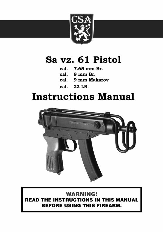
Sa vz. 61 Pistol cal. 7.65 mm Br. cal. 9 mm Br. cal. 9 mm Makarov cal. 22 LR
Instructions Manual
WARNING!READ THE INSTRUCTIONS IN THIS MANUAL
BEFORE USING THIS FIREARM.
- 2 - - 3 -
Safety Instructions WARNING!1. Carefully read the instructions and warnings in this Instruction Manual before using this firearm. Failure to follow the
instructions in this Manual could result in the following: death or serious bodily injury to the operator, death or serious bodily injury to other, and demage to property.
2. In a addition to studying and thoroughly understanding this Manual, ensure safety training is received from a com petent fireamrsm instructor before handling or using this firearm. Czech Small Arms, s.r.o. shall not be liable for any injury to persons or any damage to property resulting from the use of this friearms.
3. This Instruction Manual must accompany the firearms at all times and be transferred with the firearm in the event of a change in ownership, or when the firearm is loaned or presented to another person.
4. Always ensure the firearm and ammunition is kept away from children adn unauthorized persons by keeping the locked up. SAFETY IS YOUR RESPONSIBILITY AT ALL TIMES!
CAUTION!Ensure the following safe firearm handling is observed at all times:• Do not rely on your firearm s safety. Always treat your firearms as i fit were loaded and ready to fire. The firearm is safe
only as long as you use it safely. • Neverhandleafirearmwithoutinspectingthemagazinewellandthechambretoseeifitisloded.• Alawaysunloadthefirearmwhenfinishedshooting.• Whileunloading,alwayskeepthefirearmpointedinsafedirection,removethemagazine,emptythechamber,
and visually inspect to ensure no round is present. • Nevercroosafence,climatree,crossaditch,walk,orrunwithloadedfirearm.Firearmshavebeenknowntoaccidentally
fire when dropped, snagged, and struck.• Always be sure the barrel is clear of obstruction and only carry and load your firearm with ammunition specifically
intended for your firearm.• Never shoot a firearm that may have sustained damage. If damaged, have it examined by a competent gunsmith before
shooting.• Never load or carry a loaded firearm until you are ready to use it. Before loading, ensure you have a stable shooting
position and that your muzzle is pointed in safe direction.• Never point the muzzle of your firearm at anything that you are not willing to kill or destory.• Never place your finger on the trigger, or inside the trigger guard, until you are ready to fire.• Alaways wear eye and ear protection when shooting. Operators and bystanders must do so to prevent possible
permanent vision and/or hearing loss.• Never shoot unless you are absolutely sure of your target and what is beyond it. Rifle and handgun cartriges are very
powerful, can have a lethal range of several miles, and can often penetrate walls and metal.• Never fire at hard objects or wather as this may cause projectiles to ricochet and result in death, serious injury,
or property damage.• Never handle or shoot this firearm if you have consumed alcohol, of if you are taking drugs or medication that could
impair your vision, physical responses, or judgement.• Use only high quality, commercially manufactured ammunition in good condition. Only use ammunition that complies
with performance standards established by The Sporting Arms and Ammunition Manufacturer s Institute.• Do not alter this firearm in any way. This firearm was designed to function properly in its original condition. Alterations
can make the firearm unsafe.• Keep your firearm and ammunition separately and in locked storage away from children and unauthorized persons.
Access to the firearm and/or to ammunition by children, or unauthorized persons, could result in criminal and civil charges.
Sa vz. 61 Pistol Instruction Manual Content:
Part I. Description of the design of the Sa vz. 61 Pistol ...................................... 4Chapter 1 General ...................................................................................................................................4 1. Purpose and features of Sa vz. 61 Pistol 2. Characteristics of Sa vz. 61 Pistol Chapter 2 Description of main parts of Sa vz. 61 Pistol .....................................................................................5 1. Barrel 2. Receiver cover 3. Sights 4. Bolt 5. Receiver 6. Trigger mechanism 7. Hammer 8. Grip 9. Magazines Chapter 3 Accessories ................................................................................................................................. 12Chapter 4 Ammunition ............................................................................................................................... 12
Part II. Operation, troubleshooting, storage, inspections, maintenance and zeroing of Sa vz. 61 Pistol ......................................... 13Chapter 1 Parts and mechanism, operation of Sa vz. 61 Pistol ........................................................................ 13 1. Fire Preparation 2. Loading 3. Firing 4. Safety lever 5. Fire termination Chapter 2 Failure prevention and troubleshooting ....................................................................................... 14 1. Failure prevention 2. Failure features and troubleshootingChapter 3 Storage, disassembly, assembly and inspections of Sa vz. 61 Pistol .................................................. 15 1. Storage 2. Disassembly 3. Assembly 4. Inspections Chapter 4 Cleaning and preservation of Sa vz. 61 Pistol ................................................................................. 16Chapter 5 Zeroing of Sa vz. 61 Pistol ............................................................................................................ 16
Part III. Basic technical specifications of Sa vz. 61 Pistol ................................... 17
Part IV. List of parts ........................................................................................ 18
- 4 - - 5 -
CHAPTER 2 DESCRIPTION OF MAIN PARTS OF SA VZ. 61 PISTOL 1. Barrel (Fig. 3 and 4)
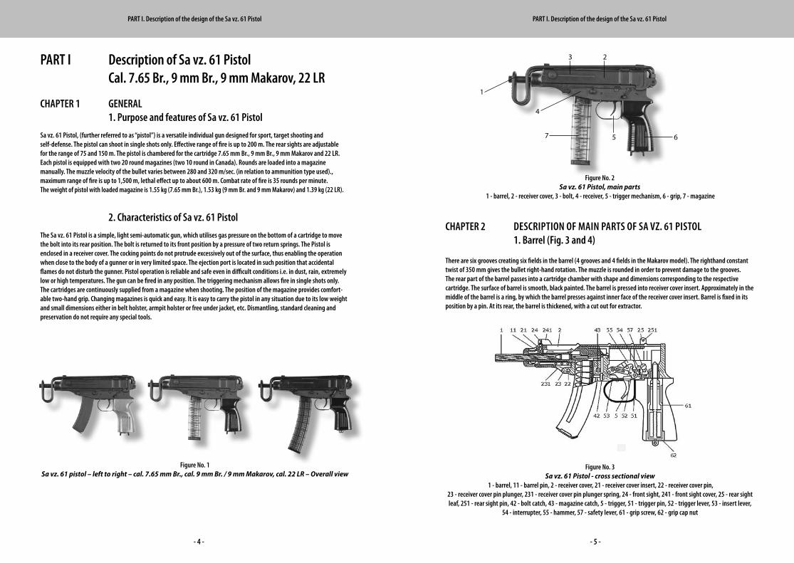
There are six grooves creating six fields in the barrel (4 grooves and 4 fields in the Makarov model). The righthand constant twist of 350 mm gives the bullet right-hand rotation. The muzzle is rounded in order to prevent damage to the grooves. The rear part of the barrel passes into a cartridge chamber with shape and dimensions corresponding to the respective cartridge. The surface of barrel is smooth, black painted. The barrel is pressed into receiver cover insert. Approximately in the middle of the barrel is a ring, by which the barrel presses against inner face of the receiver cover insert. Barrel is fixed in its position by a pin. At its rear, the barrel is thickened, with a cut out for extractor.
Figure No. 2 Sa vz. 61 Pistol, main parts
1 - barrel, 2 - receiver cover, 3 - bolt, 4 - receiver, 5 - trigger mechanism, 6 - grip, 7 - magazine
PART I Description of Sa vz. 61 Pistol Cal. 7.65 Br., 9 mm Br., 9 mm Makarov, 22 LR
CHAPTER 1 GENERAL 1. Purpose and features of Sa vz. 61 Pistol
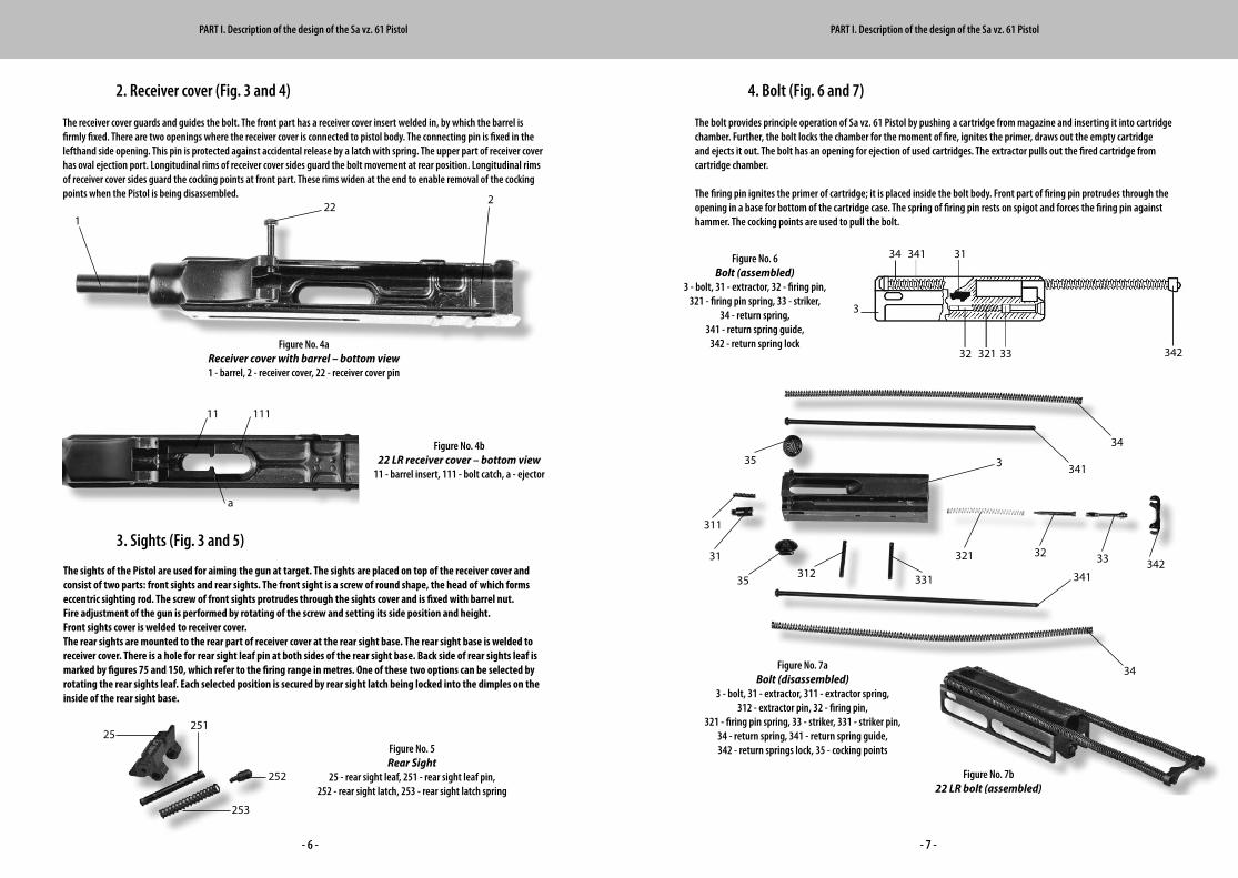
Sa vz. 61 Pistol, (further referred to as “pistol”) is a versatile individual gun designed for sport, target shooting and self-defense. The pistol can shoot in single shots only. Effective range of fire is up to 200 m. The rear sights are adjustable for the range of 75 and 150 m. The pistol is chambered for the cartridge 7.65 mm Br., 9 mm Br., 9 mm Makarov and 22 LR. Each pistol is equipped with two 20 round maga zines (two 10 round in Canada). Rounds are loaded into a magazine manually. The muzzle velocity of the bullet varies between 280 and 320 m/sec. (in relation to ammunition type used)., maximum range of fire is up to 1,500 m, lethal effect up to about 600 m. Combat rate of fire is 35 rounds per minute. The weight of pistol with loaded magazine is 1.55 kg (7.65 mm Br.), 1.53 kg (9 mm Br. and 9 mm Makarov) and 1.39 kg (22 LR).
2. Characteristics of Sa vz. 61 Pistol
The Sa vz. 61 Pistol is a simple, light semi-automatic gun, which utilises gas pressure on the bottom of a cartridge to move the bolt into its rear position. The bolt is returned to its front position by a pressure of two return springs. The Pistol is enclosed in a receiver cover. The cocking points do not protrude excessively out of the surface, thus enabling the operation when close to the body of a gunner or in very limited space. The ejection port is located in such position that accidental flames do not disturb the gunner. Pistol operation is reliable and safe even in difficult conditions i.e. in dust, rain, extremely low or high temperatures. The gun can be fired in any position. The triggering mechanism allows fire in single shots only. The cartridges are continuously supplied from a magazine when shooting. The position of the magazine provides comfort-able two-hand grip. Changing magazines is quick and easy. It is easy to carry the pistol in any situation due to its low weight and small dimensions either in belt holster, armpit holster or free under jacket, etc. Dismantling, standard cleaning and preservation do not require any special tools.
1
Figure No. 1Sa vz. 61 pistol – left to right – cal. 7.65 mm Br., cal. 9 mm Br. / 9 mm Makarov, cal. 22 LR – Overall view
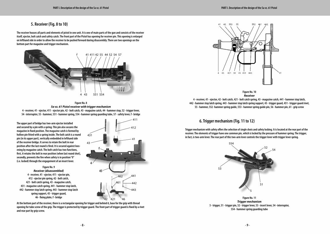
Figure No. 3 Sa vz. 61 Pistol - cross sectional view
1 - barrel, 11 - barrel pin, 2 - receiver cover, 21 - receiver cover insert, 22 - receiver cover pin,23 - receiver cover pin plunger, 231 - receiver cover pin plunger spring, 24 - front sight, 241 - front sight cover, 25 - rear sight leaf, 251 - rear sight pin, 42 - bolt catch, 43 - magazine catch, 5 - trigger, 51 - trigger pin, 52 - trigger lever, 53 - insert lever,
54 - interrupter, 55 - hammer, 57 - safety lever, 61 - grip screw, 62 - grip cap nut
PART I. Description of the design of the Sa vz. 61 Pistol PART I. Description of the design of the Sa vz. 61 Pistol
4
7 6 5
2 3
- 6 - - 7 -
4. Bolt (Fig. 6 and 7)
The bolt provides principle operation of Sa vz. 61 Pistol by pushing a cartridge from magazine and inserting it into cartridge chamber. Further, the bolt locks the chamber for the moment of fire, ignites the primer, draws out the empty cartridge and ejects it out. The bolt has an opening for ejection of used cartridges. The extractor pulls out the fired cartridge from cartridge chamber.
The firing pin ignites the primer of cartridge; it is placed inside the bolt body. Front part of firing pin protrudes through the opening in a base for bottom of the cartridge case. The spring of firing pin rests on spigot and forces the firing pin against hammer. The cocking points are used to pull the bolt.
2. Receiver cover (Fig. 3 and 4)
The receiver cover guards and guides the bolt. The front part has a receiver cover insert welded in, by which the barrel is firmly fixed. There are two openings where the receiver cover is connected to pistol body. The connecting pin is fixed in the lefthand side opening. This pin is protected against accidental release by a latch with spring. The upper part of receiver cover has oval ejection port. Longitudinal rims of receiver cover sides guard the bolt movement at rear position. Longitudinal rims of receiver cover sides guard the cocking points at front part. These rims widen at the end to enable removal of the cocking points when the Pistol is being disassembled.
Figure No. 4a Receiver cover with barrel – bottom view1 - barrel, 2 - receiver cover, 22 - receiver cover pin
Figure No. 5 Rear Sight
25 - rear sight leaf, 251 - rear sight leaf pin, 252 - rear sight latch, 253 - rear sight latch spring
Figure No. 7a Bolt (disassembled)
3 - bolt, 31 - extractor, 311 - extractor spring, 312 - extractor pin, 32 - firing pin,
321 - firing pin spring, 33 - striker, 331 - striker pin, 34 - return spring, 341 - return spring guide,342 - return springs lock, 35 - cocking points
PART I. Description of the design of the Sa vz. 61 Pistol PART I. Description of the design of the Sa vz. 61 Pistol
1
222
3
31
311
312
32321 33
331
34
34
341
341342
35
35
25251
253
252
3
31
32 321 33
34 341
342
Figure No. 4b 22 LR receiver cover – bottom view
11 - barrel insert, 111 - bolt catch, a - ejector
3. Sights (Fig. 3 and 5)
The sights of the Pistol are used for aiming the gun at target. The sights are placed on top of the receiver cover and consist of two parts: front sights and rear sights. The front sight is a screw of round shape, the head of which forms eccentric sighting rod. The screw of front sights protrudes through the sights cover and is fixed with barrel nut. Fire adjustment of the gun is performed by rotating of the screw and setting its side position and height. Front sights cover is welded to receiver cover. The rear sights are mounted to the rear part of receiver cover at the rear sight base. The rear sight base is welded to receiver cover. There is a hole for rear sight leaf pin at both sides of the rear sight base. Back side of rear sights leaf is marked by figures 75 and 150, which refer to the firing range in metres. One of these two options can be selected by rotating the rear sights leaf. Each selected position is secured by rear sight latch being locked into the dimples on the inside of the rear sight base.
Figure No. 7b 22 LR bolt (assembled)
Figure No. 6 Bolt (assembled)
3 - bolt, 31 - extractor, 32 - firing pin, 321 - firing pin spring, 33 - striker,
34 - return spring,341 - return spring guide,
342 - return spring lock
a
11 111
- 8 - - 9 -
6. Trigger mechanism (Fig. 11 to 12)
Trigger mechanism with safety offers the selection of single shots and safety locking. It is located at the rear part of the receiver. The elements of trigger have one common pin, which is locked by the pres sure of hammer spring. The trigger, in fact, is two-arm lever. The rear part of this two-arm lever controls the trigger lever with trigger lever spring.
5. Receiver (Fig. 8 to 10)
The receiver houses all parts and elements of pistol in one unit. It is one of main parts of the gun and consists of the receiver itself, ejector, bolt catch and safety catch. The front part of the Pistol has opening for receiver pin. This opening is enlarged on lefthand side in order to allow the receiver to be pushed forward during disassembly. There are two openings on the bottom part for magazine and trigger mechanism.
The upper part of bridge has two-arm ejector installed and secured by a pin with a spring. This pin also secures the magazine in fixed position. The magazine catch is formed by hollow pin fitted with a spring inside. The bolt catch is a round pin (in its upper part), vertically em bedded in lefthand side of the receiver bridge. It serves to retain the bolt in rear position after the last round is fired. It is secured against loos-ening by magazine catch. The bolt catch has two functions, first, it retains the bolt in rear position (when last round shot), secondly, prevents the fire when safety is in position “0” (i.e. locked) through the engagement of an insert lever.
At the bottom part of the receiver, there is a rectangular opening for trigger and behind it, base for the grip with thread opening for tube screw of the grip. The trigger is protected by trigger guard. The front part of trigger guard is fixed by a rivet and rear part by grip screw.
Figure No. 8 5a vz. 61 Pistol receiver with trigger mechanism
4 - receiver, 41 - ejector, 411 - ejector pin, 42 - bolt catch, 43 - magazine catch, 44 - hammer stop, 52 - trigger lever, 54 - interrupter, 55 - hammer, 551 - hammer spring, 554 - hammer spring guarding tube, 57 - safety lever, f - bridge
Figure No. 9 Receiver (disassembled)
4 - receiver, 41 - ejector, 411 - ejector pin,412 - ejector pin spring, 42 - bolt catch,
421 - bolt catch spring, 43 - magazine catch,431 - magazine catch spring, 441 - hammer stop latch,
442 - hammer stop latch spring, 443 - hammer stop latch spring support, 45 - trigger guard,
46 - fixing plate, f - bridge
Figure No. 10 Receiver
4 - receiver, 41 - ejector, 42 - bolt catch, 421 - bolt catch spring, 43 - magazine catch, 441 - hammer stop latch, 442 - hammer stop latch spring, 443 - hammer stop latch spring support, 45 - trigger guard, 451 - trigger guard rivet,
55 - hammer, 552 -hammer spring guide, 553 - hammer spring guide pin, 56 - hammer pin, 61 - grip screw
Figure No. 11 Trigger mechanism
5 - trigger, 51 - trigger pin, 52 - trigger lever, 53 - insert lever, 54 - interrupter,554 - hammer spring guarding tube
PART I. Description of the design of the Sa vz. 61 Pistol PART I. Description of the design of the Sa vz. 61 Pistol
- 6 -
1.2.5. Frame (Fig. 8 - 10)
The frame houses all parts and elements of pistol in one unit. It is one of main parts of the gun and consists of the frame itself, ejector, bolt catch and safety catch. The front part of pistol has opening for receiver pin. This opening is enlarged on left hand side in order to allow the rece-iver to be pushed forward during disassembly. There are two openings on the bottom part for magazine and trigg mechanism.
At the bottom part of the frame, there is a rectangular opening for trigger and behind it, basement for the grip with thread opening for tube screw of the grip. The trigger is protected by trigger guard. The front part of trigger guard is xed by a rivet and rear part by grip screw.
The upper part of bridge has two arm ejector in-stalled and secured by a pin with a spring. This pin also secures the magazine in xed position. The magazine catch is formed by hollow pin tted with a spring inside. The bolt catch is an oval pin (in its upper part), vertically embedded in left hand side of the frame bridge. It serves to retain the bolt in rear position after the last round is red. It is secu-red against loosening by magazine catch. The bolt catch has two functions, rst, it retains the bolt in rear position (when last round shot), secondly, pre-vents the re when safety is in position “0” (i.e. loc-ked) through the engagement of insert lever.
Figure No.: 8Sa vz. 61 pistol frame with trigger mechanism
4 – frame, 41 – ejector, 411 -ejector pin, 42 – bolt catch, 43 – magazine catch, 44 – hammer stop,52 – trigger lever, 54 – interrupter, 55 – hammer, 551 – hammer spring, 554 – hammer spring guarding tube,
57 – safety lever, f – bridge
Figure No.: 9Frame disassembled
4 – frame, 41 – ejector, 411 - ejector pin,412 – ejector pin spring, 42 – bolt catch, 421 – boltcatch spring, 43 – magazine catch, 431 – magazine
catch spring, 441 – hammer stop latch,442 – hammer stop latch spring,
443 – hammer stop latch spring support,45 trigger guard, 46 – xing plate,
461 – xing plate latch, 462 – xing plate latch spring, f – bridge
411431
43
4
45
421
f
412
41
462 441
443
4642
442461
4
41 411 42
43
44 52 54 5755
551 554
f
4
41 411 42
43
44 52 54 5755
551 554
f
42 421
441
442
443
46
461
5
51
52
53
54
554
462
- 10 - - 11 -
9. Magazines
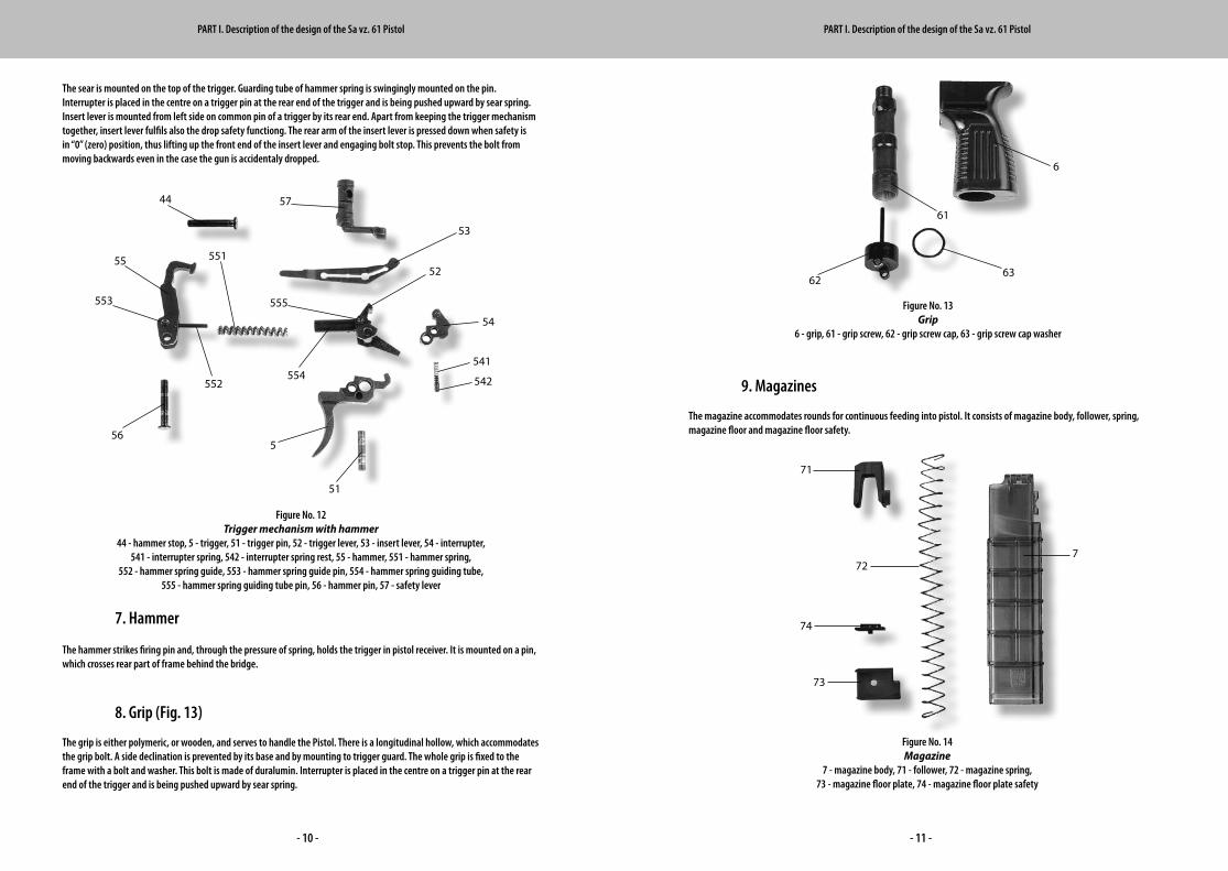
The magazine accommodates rounds for continuous feeding into pistol. It consists of magazine body, follower, spring, magazine floor and magazine floor safety.
The sear is mounted on the top of the trigger. Guarding tube of hammer spring is swingingly mounted on the pin. Interrupter is placed in the centre on a trigger pin at the rear end of the trigger and is being pushed upward by sear spring. Insert lever is mounted from left side on common pin of a trigger by its rear end. Apart from keeping the trigger mechanism together, insert lever fulfils also the drop safety functiong. The rear arm of the insert lever is pressed down when safety is in “0” (zero) position, thus lifting up the front end of the insert lever and engaging bolt stop. This prevents the bolt from moving backwards even in the case the gun is accidentaly dropped.
7. Hammer
The hammer strikes firing pin and, through the pressure of spring, holds the trigger in pistol receiver. It is mounted on a pin, which crosses rear part of frame behind the bridge.
8. Grip (Fig. 13)
The grip is either polymeric, or wooden, and serves to handle the Pistol. There is a longitudinal hollow, which accommodates the grip bolt. A side declination is prevented by its base and by mounting to trigger guard. The whole grip is fixed to the frame with a bolt and washer. This bolt is made of dura lumin. Interrupter is placed in the centre on a trigger pin at the rear end of the trigger and is being pushed upward by sear spring.
Figure No. 12Trigger mechanism with hammer
44 - hammer stop, 5 - trigger, 51 - trigger pin, 52 - trigger lever, 53 - insert lever, 54 - interrupter,541 - interrupter spring, 542 - interrupter spring rest, 55 - hammer, 551 - hammer spring,
552 - hammer spring guide, 553 - hammer spring guide pin, 554 - hammer spring guiding tube,555 - hammer spring guiding tube pin, 56 - hammer pin, 57 - safety lever
Figure No. 13Grip
6 - grip, 61 - grip screw, 62 - grip screw cap, 63 - grip screw cap washer
Figure No. 14Magazine
7 - magazine body, 71 - follower, 72 - magazine spring,73 - magazine floor plate, 74 - magazine floor plate safety
PART I. Description of the design of the Sa vz. 61 Pistol PART I. Description of the design of the Sa vz. 61 Pistol
7
565
51
52
53
54
541
542
55
44
552
553
554
555
57
55163
62
61
6
71
72
74
73
- 12 - - 13 -
PART II Operation, troubleshooting, storage, inspections, maintenance and zeroing of Sa vz. 61 Pistol
CHAPTER 1 PARTS AND MECHANISM, OPERATION OF Sa vz. 61 PISTOL 1. Preparation for shooting
The Pistol, which has been preserved for long storage, must be disassembled, cleaned and reassembled before use. All remnants of vaseline have to be removed and all movable parts oiled.
2. Loading
Insert loaded magazine into a gun until a click is heard. Turn the safety from position ”0” to position “1”. Holding the cocking points firmly, pull the bolt backwards till it stops and release. The bolt returns into front position and brings cartridge to the chamber and closes the chamber itself. This being done, the gun is ready to fire.
3. Firing
After pulling the trigger a sequence of movements in trigger mechanism results in hammer hitting a striker and igniting a primer, thus resulting in a shot. Part of powder gases thrusts onto cartridge case bottom and front wall of the bolt, ejecting the bolt into rear position. This energy suppresses the springs, ejects the cartridge and renews the operating position of the hammer. The empty cartridge is ejected upward and away from the shooter. The restored forward motion causes the new feeding of next cartridge to chamber. The trigger must be released after each shot. The pistol is ready for next single shot by new action of the trigger.
4. Safety lever
The gun is safely locked by turning the safety lever to position ”0”, i. e. pointing downward. Thus, the trigger cannot be pressed, accidental fire is prevented.
5. Fire termination
Should fire be terminated, it is recommended to pull out the magazine and draw the bolt into its rear position. The last unused cartridge should be ejected from the chamber this way only. Then, the bolt should be released again to its front position and the gun locked by the safety lever (into position “0”).
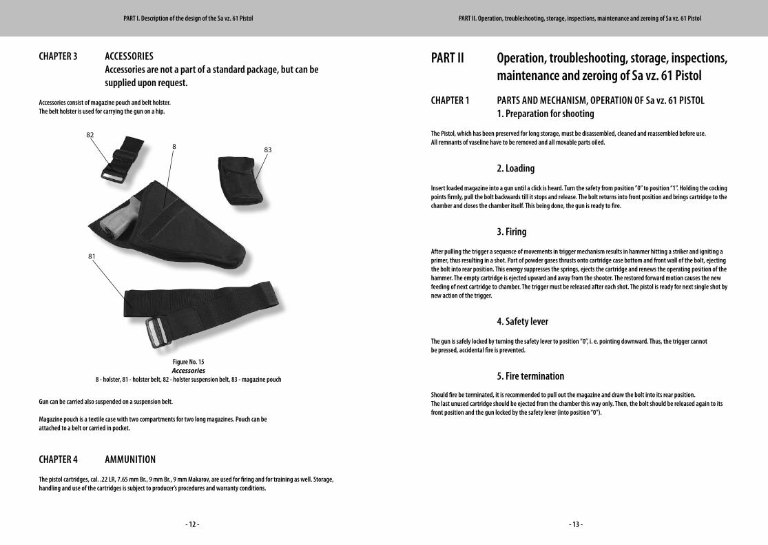
CHAPTER 3 ACCESSORIES Accessories are not a part of a standard package, but can be supplied upon request.
Accessories consist of magazine pouch and belt holster. The belt holster is used for carrying the gun on a hip.
Gun can be carried also suspended on a suspension belt.
Magazine pouch is a textile case with two compartments for two long magazines. Pouch can be attached to a belt or carried in pocket.
CHAPTER 4 AMMUNITION
The pistol cartridges, cal. .22 LR, 7.65 mm Br., 9 mm Br., 9 mm Makarov, are used for firing and for training as well. Storage, handling and use of the cartridges is subject to producer’s procedures and warranty conditions.
Figure No. 15Accessories
8 - holster, 81 - holster belt, 82 - holster suspension belt, 83 - magazine pouch
PART I. Description of the design of the Sa vz. 61 Pistol PART II. Operation, troubleshooting, storage, inspections, maintenance and zeroing of Sa vz. 61 Pistol
8
81
82
83
- 14 - - 15 -
CHAPTER 3 STORAGE, DISSASEMBLY, ASSEMBLY AND CHECKS OF Sa vz. 61 PISTOL 1. Storage
The Pistol has to be stored with bolt in front position in order not to overstrain the springs; the safety must be in position “0”. The gun should be disassembled, cleaned and assembled after each use. Special attention must be paid to cleaning of the barrel and cartridge chamber.
2. Dissasembly
Disassembly of the Pistol is partial or complete. The complete disassembly is executed only in specialized workshops for repair reasons by authorized gunsmiths. Partial disassembly can be performed by each individual user. Attention should be paid to tiny components when disassembling the Pistol.
Always make sure the gun is not loaded, remove the magazine and check the cartridge chamber. Regular check and maintenance require opening of the bolt and receiver cover only. This provides sufficient access to trigger mechanism and receiver. Partial dissasembly: a) Remove the magazine. b) Remove the receiver cover by pressing protruding end of receiver cover pin on right side of receiver, pull out the connecting pin to left until it stops, push the receiver cover forward and tilt it up. c) Remove the bolt by drawing it to rear position, remove both cocking points and the bolt itself from the receiver.
Complete dissasembly: a) Perform partial disassembly first. b) Disassemble the bolt by removing the lock of return springs and guiding rods of return springs, knock out firing pin by using puncher, remove the striker and Its spring. c) Knock out the pin of extractor by using the puncher and pull out extractor with its spring. d) Separate receiver cover from the receiver by pulling out receiver cover pin till it stops and remove the pin with spring by applying pressure of a puncher. e) Dismantle the trigger and hammer - push the fixing plate latch and pull out the front end of fixing plate, pull out the fixing plate latch with its spring as well as hammer stop latch, remove hammer stop, turn the safety lever forward and pull it out, remove the trigger by pushing forward and releasing the hammer pin, pull out the hammer spring and insert lever, pull out the trigger pin and separate disconnector, sear and trigger, pull out hammer pin and hammer. f) Dismantle the ejector, bolt catch and magazine catch by pushing ejector safety pin by puncher.
3. Assembly
Follow up the reverse procedure to assemble the Pistol after all components are entirely cleaned, dry and preserved.
CHAPTER 2 TROUBLESHOOTING 1. Failure prevention
Wellpreserved,storedandpreparedPistolisfreefromdefectsanditisaveryreliablegun.However,longtermutilizationin adverse conditions, coarse impurities in the gun mechanism, defected cartridges and misuse might cause failures in operation and may even damage the gun.
Failures can be prevented, if: - Rules of maintenance, disassembly, assemby, cleaning, inspections etc. are duly followed, - Harsh and dusty conditions are avoided, - Excessive force is not used while fixing failures, - Defective and dirty cartridges are not fired, - Moving parts are oiled and the barrel and chamber cleaned and wiped dry.
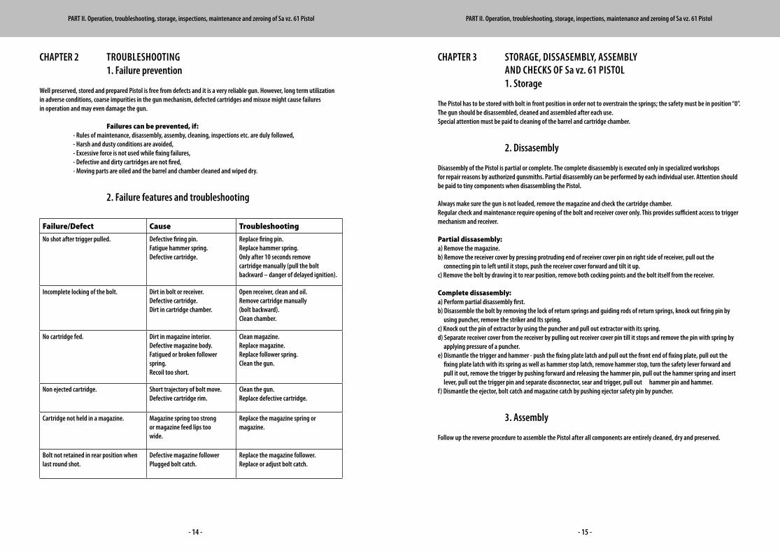
2. Failure features and troubleshooting
Failure/Defect Cause Troubleshooting
No shot after trigger pulled. Defective firing pin. Fatigue hammer spring.Defective cartridge.
Replace firing pin. Replace hammer spring.Only after 10 seconds re move cartridge manually (pull the bolt backward – danger of delayed ignition).
Incomplete locking of the bolt. Dirt in bolt or receiver. Defective cartridge.Dirt in cartridge chamber.
Open receiver, clean and oil. Remove cartridge manually (bolt backward). Clean chamber.
No cartridge fed. Dirt in magazine interior. Defective magazine body. Fatigued or broken follower spring.Recoil too short.
Clean magazine. Replace magazine.Replace follower spring.Clean the gun.
Non ejected cartridge. Short trajectory of bolt move. Defective cartridge rim.
Clean the gun.Replace defective cartridge.
Cartridge not held in a magazine. Magazine spring too strong or magazine feed lips too wide.
Replace the magazine spring or magazine.
Bolt not retained in rear position when last round shot.
Defective magazine follower Plugged bolt catch.
Replace the magazine follower. Replace or adjust bolt catch.
PART II. Operation, troubleshooting, storage, inspections, maintenance and zeroing of Sa vz. 61 Pistol PART II. Operation, troubleshooting, storage, inspections, maintenance and zeroing of Sa vz. 61 Pistol
- 16 - - 17 -
PART III Basic Technical Specifications of Sa vz. 61 Pistol 4. Inspections of Sa vz. 61 Pistol
Inspecting of assembled Pistol •Inspecttheconditionofcomponentsforcorrosion,dirt,completeness.•Checkthesights.•Reviewmovabilityofboltandtrigger.•Checkwhethermagazinesareundamaged.
Inspecting of disassembled Pistol •Cleanallcomponentsbeforechecking.•Checkcorrosion,dirtandexcessivewear-outofcomponents.•Inspectcarefullythebarrelboreandgrooves(remnantsofpowder,corrosion,darkstains,wear of fields, barrel swell or cavities and mechanical damage). •Checkcarefullythecompletenessofallcomponentsbeforeassembly.
CHAPTER 4 CLEANING AND PRESERVATION OF Sa vz. 61 PISTOL
Thorough and careful cleaning and preservation is necessary for long-term troublefree operation of the gun, fire precision and overall lifetime. Clean and soft cloths are recommended for cleaning the gun and accessories. Vaseline should be used for preservation to protect the pistol against corrosion during long term storage. It is recommended to use a mixture of gun oil and vaseline (3:1 ratio) for the use at temperatures below 0 °C.
CHAPTER 5 ZEROING OF Sa vz. 61 PISTOL
Each pistol is zeroed by the producer. New zeroing is required only when the pistol is significantly damaged (mainly the sights) and when converted for other than prescribed ammunition. The fire adjustment can be performed only by highly qualified staff.
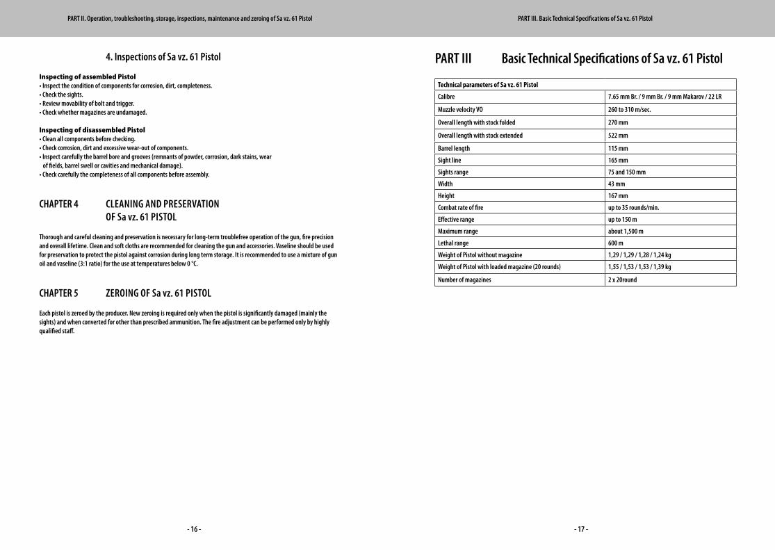
Technical parameters of Sa vz. 61 Pistol
Calibre 7.65 mm Br. / 9 mm Br. / 9 mm Makarov / 22 LR
Muzzle velocity VO 260 to 310 m/sec.
Overall length with stock folded 270 mm
Overall length with stock extended 522 mm
Barrel length 115 mm
Sight line 165 mm
Sights range 75 and 150 mm
Width 43 mm
Height 167 mm
Combat rate of fire up to 35 rounds/min.
Effective range up to 150 m
Maximum range about 1,500 m
Lethal range 600 m
WeightofPistolwithoutmagazine 1,29 / 1,29 / 1,28 / 1,24 kg
WeightofPistolwithloadedmagazine(20rounds) 1,55 / 1,53 / 1,53 / 1,39 kg
Number of magazines 2 x 20round
PART II. Operation, troubleshooting, storage, inspections, maintenance and zeroing of Sa vz. 61 Pistol PART III. Basic Technical Specifications of Sa vz. 61 Pistol
- 18 - - 19 -
PART IV List of componentsList of parts of Sa vz. 61 Pistol
PART IV. List of components PART IV. List of components
61-1-001 barrel cal. 7.65 mm Br.
61-4-001 barrel cal. 9 mm Br.
61-5-001 barrel cal. 9×18 mm Makarov
61-6-001 barrel cal. 22 LR
61-1-011 barrel pin
61-6-011 barrel insert for cal. 22 LR
61-6-111 bolt catch 22 LR
61-6-112 bolt catch pin 22 LR
61-6-113 bolt catch pin spring 22 LR
61-6-012 barrel insert pin 22 LR
61-1-002 receiver
61-1-021 receiver insert
61-1-022 receiver pin
61-1-023 receiver pin plunger
61-1-231 receiver pin plunger spring
61-1-024 front sight
61-1-241 front sight cover
61-1-025 rear sight
61-1-251 rear sight pin
61-1-252 rear sight latch
61-1-253 rear sight latch spring
61-1-003 bolt for cal. 7.65 mm Br.
61-4-003 bolt for cal. 9 mm Br.
61-5-003 bolt for cal. 9×18 mm Makarov
61-6-003 bolt for cal. 22 LR
61-1-031 extractor
61-6-031 extractor 22 LR
61-1-311 extractor spring
61-1-312 extractor pin
61-6-312 extractor pin 22 LR
61-1-032 firing pin
61-6-032 firing pin 22 LR
61-1-321 firing pin spring
61-1-033 striker
61-1-331 striker pin
61-6-331 striker pin 22 LR
61-1-034 return spring
61-4-034 return spring 9 mm Br. / 9 mm Makarov
61-6-034 return spring 22 LR
61-1-341 return spring guide
61-1-342 return spring lock
61-1-035 cocking point frame
61-1-041 ejector
61-6-041 safety plate
61-1-411 ejector pin
61-1-412 ejector pin spring
61-1-042 bolt catch
61-1-421 bolt catch spring
61-1-043 magazine catch
61-1-431 magazine catch spring
61-1-044 hammer stop
61-1-441 hammer stop latch
61-1-442 hammer stop latch spring
61-1-443 hammer stop latch spring support
61-1-045 trigger guard
61-1-451 trigger guard rivet
61-1-046 fixing plate
61-1-461 fixing plate latch
61-1-462 fixing plate latch spring
61-1-005 trigger
61-1-051 trigger pin
61-1-052 trigger lever
61-1-053 insert lever
61-1-054 interrupter
61-1-541 interrupter spring
61-1-542 interrupter spring rest
61-1-055 hammer
61-1-551 hammer spring
61-1-552 hammer spring guide
61-1-553 hammer spring guide pin
61-1-554 hammer spring guarding tube
61-1-555 hammer spring guarding tube pin
61-1-056 hammer pin
61-1-057 safety lever
61-1-006 grip
61-1-061 grip screw
61-1-062 grip cap
61-1-063 grip cap washer
61-1-007 magazine body, cal. 7.65 mm
61-4-007 magazine body, cal. 9 mm Br.
61-5-007 magazine body, cal. 9 mm Makarov
61-6-007 magazine 22 LR – 20 rd.
61-1-071 magazine follower, cal. 7.65 mm
61-4-071 magazine follower, cal. 9 mm
61-6-071 magazine follower 22 LR
61-1-072 magazine spring
61-4-072 magazine spring 9 mm Br. / 9 mm Makarov
61-6-072 magazine spring 22 LR
61-1-073 magazine floor plate, cal. 7.65 mm Br.
61-4-073 magazine floor plate, cal. 9 mm
61-6-073 magazine floor plate 22 LR
61-1-074 magazine floor plate safety cal. 7.65mm Br.
61-4-074 magazine floor plate safety,cal. 9 mm
61-6-074 magazine floor plate safety 22 LR
61-1-008 holster
61-1-081 holster belt
61-1-082 holster suspension belt
61-1-083 magazine pouch
61-1-009 folding stock
61-1-091 folding stock hinge
61-1-911 folding stock hinge pin
61-1-912 folding stock hinge safety pin
61-1-913 folding stock hinge spring
61-1-914 folding stock bracket

Czech Small Arms, s.r.o.
Jablůnka 651 | 756 23 Jablůnka | Czech Republic
cell: +420 774 298 603 | fax: +420 571 452 201
[email protected] | www.csa.co.cz


![Spis treści - AVX HOSTING · 2 heco@heco.pl Średnice zewnętrzne wg różnych typoszeregów DN ISO [mm] CAL [cal] ANSI / ASTM [mm] METRYCZNY [mm] DIN [mm] DIN 11850 SMS Rząd 1](https://img.pdfslide.net/doc/110x75/5b6bb0d87f8b9a60188dd0a9/spis-tresci-avx-2-hecohecopl-srednice-zewnetrzne-wg-roznych-typoszeregow.jpg)