Embed Size (px)
Citation preview
7/27/2019 Calculation and visualization of inductances and magnetic force of a coil iron nucleus
http://slidepdf.com/reader/full/calculation-and-visualization-of-inductances-and-magnetic-force-of-a-coil-iron 1/9
IOSR Journal of Electrical and Electronics Engineering (IOSR-JEEE)e-ISSN: 2278-1676,p-ISSN: 2320-3331, Volume 9, Issue 1 Ver. I (Jan. 2014), PP 83-91www.iosrjournals.org
www.iosrjournals.org 83 | Page
Calculation and visualization of inductances and magnetic force
of a coil iron nucleus
Mazouz Azeddine1, Hedjazi Djemai
1, Chaghi Abdelaaziz
1
1(Department of electrical Engineering University of Batna ALGERIA)
Abstract: The paper describes the investigation and development of a structure and performancecharacteristics of a coil iron nucleus cylindrical (C.I.N.C).
The coil iron nucleus cylindrical is a nonlinear electro radio in which the moving of the nucleus in a sense or in
other causes change in inductance and can reach extreme values at the superposition of nucleus and coil
centers. The variation of the inductance and the degree of freedom of movement of the nucleus can lead to a
device with electromechanical conversion The aim of this paper is the determination and visualization of self
inductance and mutual of the (C.I.N.C) based on geometric dimensions and the displacement of the nucleus.
Keywords: Coil, iron, nucleus cylindrical, linear motor, inductance.
I. INTRODUCTION
The cylindrical coil with iron nucleus can be explored as a tubular linear motor oscillation (C.I.N.C)
[3]. This type of engine is based on the periodic variation of the inductance, which causes the change in the
behaviour of the electrical circuit with the existence of a series capacitance.
The C.I.N.C with mobile induct exists in two disposition, vertical and horizontal [4],[5].The stationary part consists of a solenoid which forms part of the resonant RLC circuit. The ferromagnetic
cylinder inserted in the solenoid constitutes the moving part.
Parametric electromechanical elements, comprehend a class of single machine which present certain common
characteristics [6], [7]. The process of energy conversion is similar to some type of asynchronous motor [1].
Power conversion is due to a regular change of the parameters, that is why is called parametric machines. The
functioning of this type of machine is based on the application of electromechanical oscillations. [7] and [8].
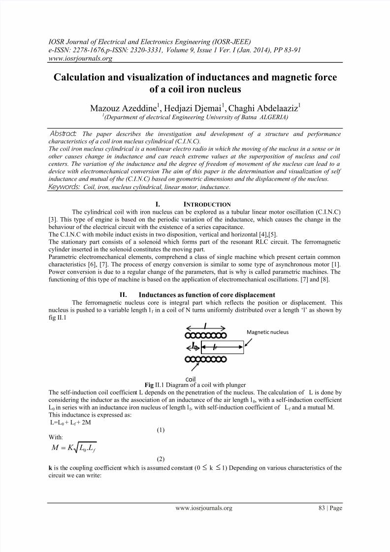
II. Inductances as function of core displacementThe ferromagnetic nucleus core is integral part which reflects the position or displacement. This
nucleus is pushed to a variable length l f in a coil of N turns uniformly distributed over a length ‘l’ as shown by
fig II.1
Fig II.1 Diagram of a coil with plungerThe self-induction coil coefficient L depends on the penetration of the nucleus. The calculation of L is done by
considering the inductor as the association of an inductance of the air length l0, with a self-induction coefficient
L0 in series with an inductance iron nucleus of length lf , with self-induction coefficient of Lf and a mutual M.
This inductance is expressed as:
L=L0 + Lf + 2M
(1)With:
f L L K M .0
(2)
k is the coupling coefficient which is assumed constant (0 k 1) Depending on various characteristics of the
circuit we can write:
Coil
l 0 l
Magnetic nucleus
l L
7/27/2019 Calculation and visualization of inductances and magnetic force of a coil iron nucleus
http://slidepdf.com/reader/full/calculation-and-visualization-of-inductances-and-magnetic-force-of-a-coil-iron 2/9
Calculation and visualization of inductances and magnetic force of a coil iron nucleus
www.iosrjournals.org 84 | Page
)(..2
2
0002
2
00 f l l S L
N l S
l
N L
(3)
f f f S S l
N
L )1([. 02
2
0 ] f l
(4)
The expression of L is then:
).)(.)]1([2).1((. 000002
2
0 f f p l l l S S k l S l S l
N L
The displacement f l of the nucleus, leads to a variation L of the inductance, which depends on lf which is
a nonlinear function of f l as in the case of air gap variable inductance of Lf . [2].
III. Inductances equations development To determine the expression (1) we need to calculate the inductances L0, Lf and M:
I I I .1. I nductance without nucleusIn this case the expression of the inductance is given by:
l
l l S
l
N
l
l S
l
N L
f )(..
02
00
0
2
00
(6)
Where: f l l l 0
S0 is the vacuum section
l
l S N S
l
N l
f 0
2
0
0
2
00
(7)
We have:
l nr L .... 22
0 (8)
With:l
N n
l
S N l
l
S N L 0
2
0
2
0
2
0 ...
. (9)
So:
)1.(.0l
l L
l
l L L L
f f (10)
lf is a function of displacement x, to be determined later.
We set: La
So:l
Lb
f l ba L .0 (11)
Inductance of the nucleus
l
l S S
l
N L
f
f f f ].).1([.
0
2
0
(12)
With:
l
l S S
S
L L
f
f f f ].).1([ 0
0
(13)
f f
f
f f l l S
S Ll S L L ).1(
...
00
(14)
7/27/2019 Calculation and visualization of inductances and magnetic force of a coil iron nucleus
http://slidepdf.com/reader/full/calculation-and-visualization-of-inductances-and-magnetic-force-of-a-coil-iron 3/9
Calculation and visualization of inductances and magnetic force of a coil iron nucleus
www.iosrjournals.org 85 | Page
We set: )1.(.0
f
f
S
S bc
And we replace by the constant (b) we have:
f f l cb L ).( (15)
I I I .2. Mutual inductance
In equation (2) we replace the expressions (10) and (14) we will have:
f f f f l l l S S S l
k
S
L M ).].().1([. 00
0
(16)
We set: ]).1([ 00 f f S S S d
And we replace the constant (b) we have:
f f l l l d bS
k M )..(..
0
(17)
I I I .3. Total inductance (coil over nucleus)
The total inductance of the coil is determined by taking the expressions of the different inductances obtained
before
f f f
f l S
l S
k L I I
l S
S L L L )l-}(lI)S-(+{S
2)( f f f 00
00
(18)
The inductance expressed as a function of the constants (a, b, c and d) is:
f f f l l l d bS
k l ca L ).(..
2.
0
(19)
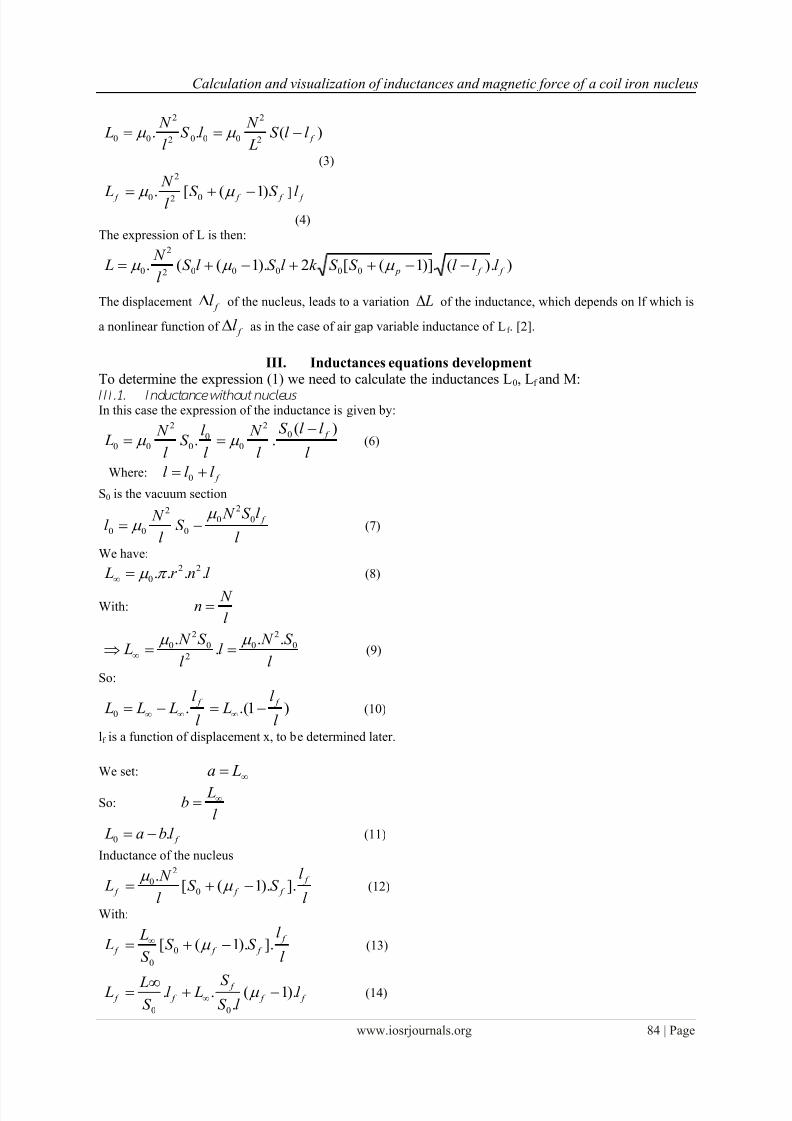
IV. COIL PARAMETERS I V.1. Coil without ir on nucleus
Under variable tension of 50 Hz frequency, the parameters indicated in table IV.1 are measured by
considering the circuit indicated in fig IV.1
Fig IV.1 Practical measuring circuit
Table IV.1
Measured parameters
UL (v) I(A) Z
9.5 0.45 21.1
13.0 0.6 22
15.6 0.7 22.28
18.3 0.8 22.87
The inductive reactance: X0= ²² R Z =L.ω;
Inductance: L0 = X0 /ω;
The impedance: Z0 average =22 ;
The internal resistance of the coil: R = 10.55;The inductance of the coil without its nucleus L0 = 0.06 H.
The internal resistance of the coil without nucleus can be determined by using the same circuit feed by direct
current.
7/27/2019 Calculation and visualization of inductances and magnetic force of a coil iron nucleus
http://slidepdf.com/reader/full/calculation-and-visualization-of-inductances-and-magnetic-force-of-a-coil-iron 4/9
Calculation and visualization of inductances and magnetic force of a coil iron nucleus
www.iosrjournals.org 86 | Page
IV.2. Coil with iron’s nucleus
Before performing the test, we must provide the core inside the coil and make sure it is centered and gradually
feeding the circuit with an alternative tension of 50Hz frequency. The indications of measuring devices are
shown in table IV.2
Table IV.2 The indications of measuring
UL (v) I(A) P(w) Ir Ur UL Z
16,7 0.05 0.83 0.0025 332 - 334
35 0.1 0.95 0.01 95 - 350
53 0.15 1.05 0.0225 46.67 25.11 353.33
96 0.3 2.06 0.09 22.89 93.23 320
150 0.484.32
0.2304 18.75 148.82 312.5
225 0.79.45
0.49 19.3 224.17 321.43
with: Zaverage=332 , R=10,55 , L=1.116H
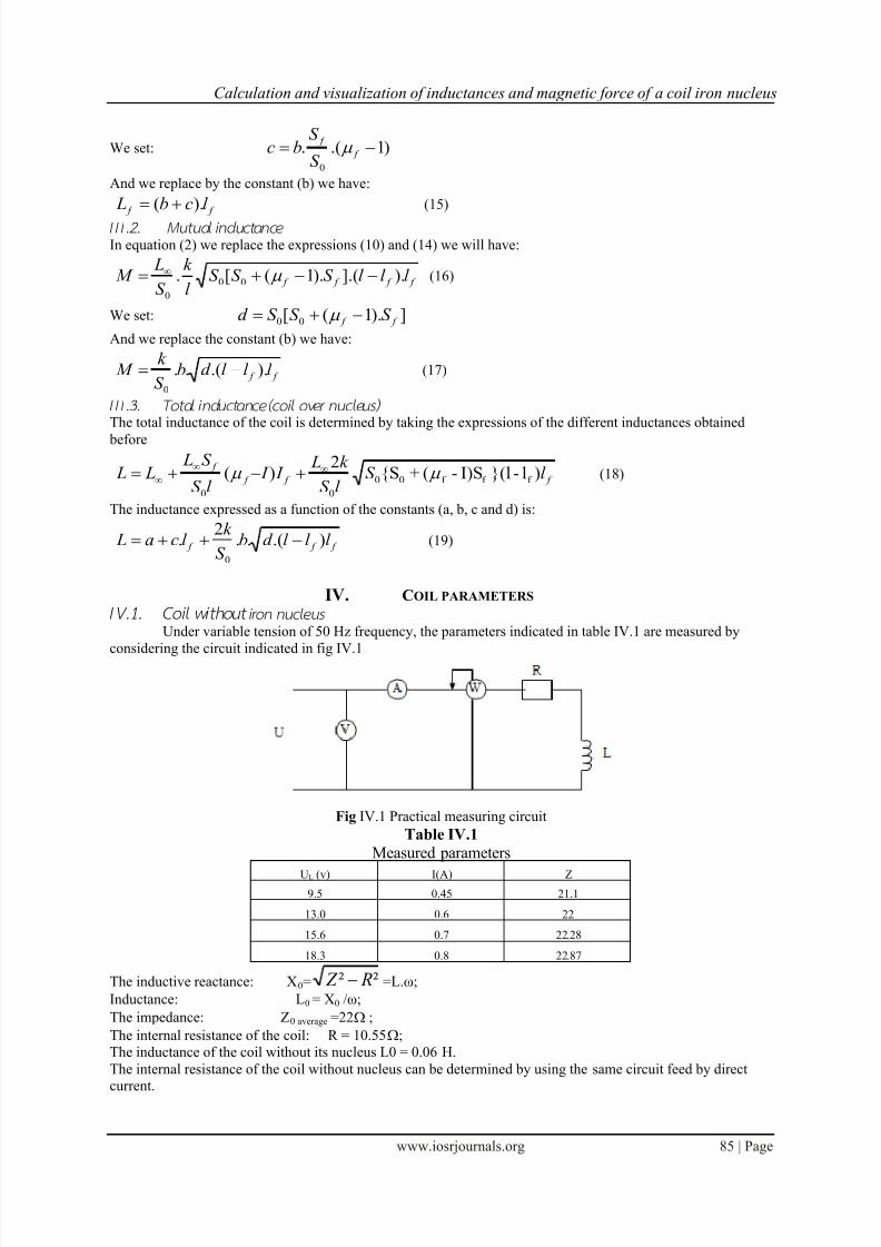
I V.3. I nductance Var iation in function of nucleus positi onThe coil with iron’s nucleus is characterized by the variation of its inductance in function of the
movement of the nucleus inside the coil. Taking reference as the superposition of the coil’s and the nucleus’s
centre as indicated in figure IV.2.
The manually movement of the nucleus along the axis X passes through 03 zones. For the left and right areas,
the coil is without nucleus and the inductance takes a minimum value.
However for the intermediate area the nucleus occupied gradually the total of the coil to pursue the air that itcontains and in this case the inductance becomes max.
Fig IV.2 Representative patterns of the core displacement.
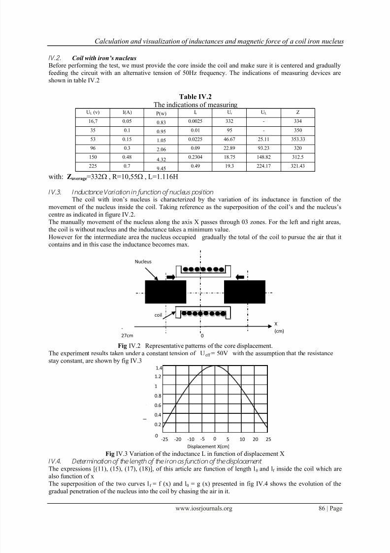
The experiment results taken under a constant tension of Ueff = 50V with the assumption that the resistance
stay constant, are shown by fig IV.3
Fig IV.3 Variation of the inductance L in function of displacement X
I V.4. Determi nation of the length of the ir on as function of the displacement
The expressions [(11), (15), (17), (18)], of this article are function of length l0 and lf inside the coil which arealso function of x
The superposition of the two curves l f = f (x) and l0 = g (x) presented in fig IV.4 shows the evolution of thegradual penetration of the nucleus into the coil by chasing the air in it.
0
Nucleus
X
(cm)
coil
-
27cm
1.4
1.2
-5 0 5 2010-10-20-250
0.2
0.4
1
0.8
0.6
25
I
Displacement X(cm)
7/27/2019 Calculation and visualization of inductances and magnetic force of a coil iron nucleus
http://slidepdf.com/reader/full/calculation-and-visualization-of-inductances-and-magnetic-force-of-a-coil-iron 5/9
Calculation and visualization of inductances and magnetic force of a coil iron nucleus
www.iosrjournals.org 87 | Page
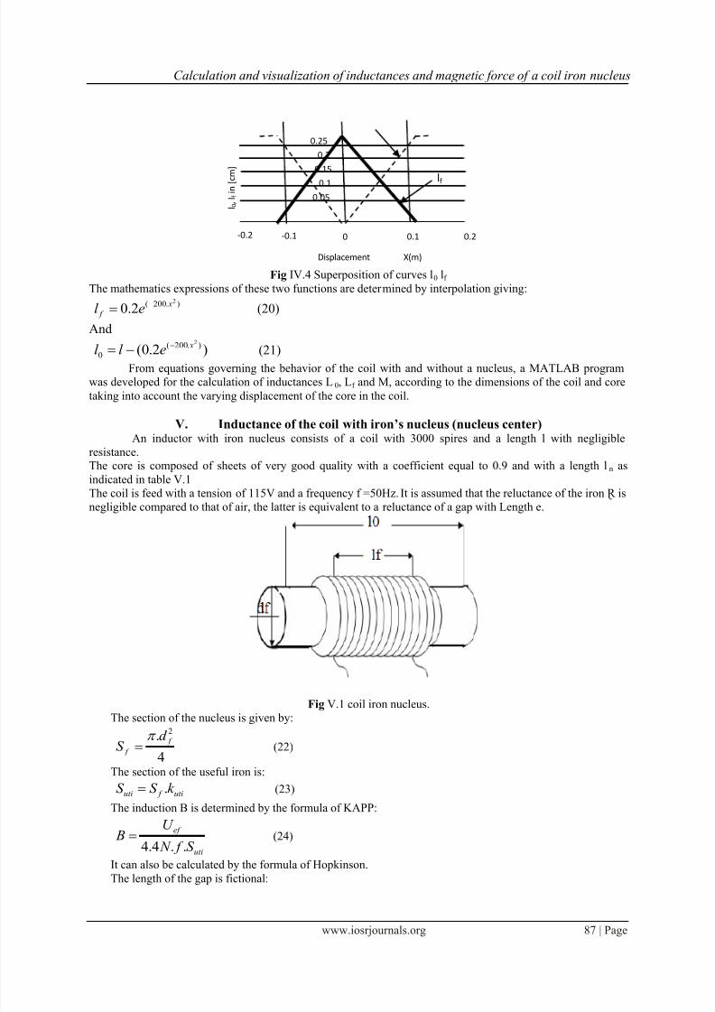
Fig IV.4 Superposition of curves l0 lf
The mathematics expressions of these two functions are determined by interpolation giving:
).200( 2
2.0 x
f el (20)
And
)2.0(
).200(
0
2 x
el l
(21)From equations governing the behavior of the coil with and without a nucleus, a MATLAB program
was developed for the calculation of inductances L0, Lf and M, according to the dimensions of the coil and core
taking into account the varying displacement of the core in the coil.
V. Inductance of the coil with iron’s nucleus (nucleus center) An inductor with iron nucleus consists of a coil with 3000 spires and a length l with negligible
resistance. The core is composed of sheets of very good quality with a coefficient equal to 0.9 and with a length ln as
indicated in table V.1
The coil is feed with a tension of 115V and a frequency f =50Hz.It is assumed that the reluctance of the iron Ɽ is
negligible compared to that of air, the latter is equivalent to a reluctance of a gap with Length e.
Fig V.1 coil iron nucleus.The section of the nucleus is given by:
4
. 2
f
f
d S
(22)
The section of the useful iron is:
uti f uti k S S . (23)
The induction B is determined by the formula of KAPP:
uti
ef
S f N
U B
..4.4 (24)
It can also be calculated by the formula of Hopkinson.
The length of the gap is fictional:
l 0 ,
l f i n [ c m ]
0
0.1
0.2
-0.1-0.2
0.05
0.1
0.15
0.2
0.25
lf
Displacement X(m)
7/27/2019 Calculation and visualization of inductances and magnetic force of a coil iron nucleus
http://slidepdf.com/reader/full/calculation-and-visualization-of-inductances-and-magnetic-force-of-a-coil-iron 6/9
Calculation and visualization of inductances and magnetic force of a coil iron nucleus
www.iosrjournals.org 88 | Page
n
uti
l
l S e
..28.0 (25)
The volume of air to magnetize:
uti
S eV . (26)
The reactive power needed for the gap:
62
10.5.2
.. V BQ
(27)
The active power is low because f and B are weak.
The fictional absorbed current is:
ef
r U
Q I (28)
This current can be considered as total current, which can also be determined by applying the formula of
Hopkinson.
.ef NI (29)
So:
2..
1
2.
.
00 N
el
S N I m
r
nmef
(30)
With:
0.0
r
l
(31)
The impedance of the circuit is:
ef
ef
I
U L Z .
(32)
When the inductance of the coil is:
Z L (33)
A MATLAB program has been designed to perform calculations of inductance for a coil with centered
nucleus.
VI. The coil characteristicsThe characteristics of the coil considered are shown in the table VI.1, which summarizes all the
electrical and geometrical dimensions.
Table VI.1 Electrical and geometrical dimensions of C.I.N.C
Elements Dimensional Symbols Values
Coil
LengthOutside diameterInside diameter
Conductor diameter
Inductance Without core
nucleus inductor
internal resistance
ldd0
d
L0
L
R
22.0[cm]6.4[cm]3.0[cm]
1 [mm]
0.04 [H]
1.1[H]
10 [Ω]
NucleusLengthDiameter
Mass
lf df
m
26[cm]2.9 [cm]
0.65[mm]
Air gap Thickness e1 0.1 [mm]
VII. Calculation and visualization of inductors according to the position of the nucleus The results of simulation of the inductances L0, Lf , M and L in function of displacement (x) of the
nucleus affected under MATLAB program, are giving by the following figures:
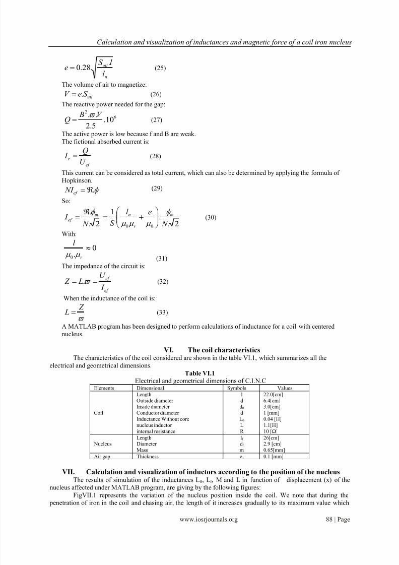
FigVII.1 represents the variation of the nucleus position inside the coil. We note that during the penetration of iron in the coil and chasing air, the length of it increases gradually to its maximum value which
7/27/2019 Calculation and visualization of inductances and magnetic force of a coil iron nucleus
http://slidepdf.com/reader/full/calculation-and-visualization-of-inductances-and-magnetic-force-of-a-coil-iron 7/9
Calculation and visualization of inductances and magnetic force of a coil iron nucleus
www.iosrjournals.org 89 | Page
corresponds to the total occupation, then a regression of the curve that corresponds to t progressive removal
core, knowing that the length of the coil l = l0 + lf .
The curve of evolution of the air inside the coil is represented by Fig VII.1 and on which are
superimposed the two curves l0 and lf .
FigVII.1 Superposition of l0 = f (x) and lf =g (x)
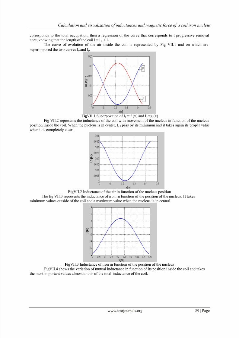
Fig VII.2 represents the inductance of the coil with movement of the nucleus in function of the nucleus
position inside the coil. When the nucleus is in center, L0 pass by its minimum and it takes again its proper value
when it is completely clear.
FigVII.2 Inductance of the air in function of the nucleus position
The fig VII.3 represents the inductance of iron in function of the position of the nucleus. It takesminimum values outside of the coil and a maximum value when the nucleus is in central.
FigVII.3 Inductance of iron in function of the position of the nucleus
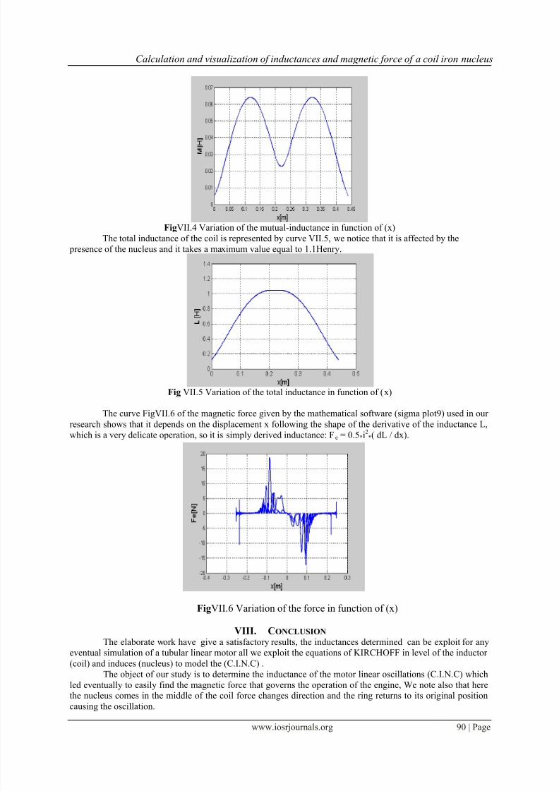
FigVII.4 shows the variation of mutual inductance in function of its position inside the coil and takes
the most important values almost to this of the total inductance of the coil.
7/27/2019 Calculation and visualization of inductances and magnetic force of a coil iron nucleus
http://slidepdf.com/reader/full/calculation-and-visualization-of-inductances-and-magnetic-force-of-a-coil-iron 8/9
Calculation and visualization of inductances and magnetic force of a coil iron nucleus
www.iosrjournals.org 90 | Page
FigVII.4 Variation of the mutual-inductance in function of (x)
The total inductance of the coil is represented by curve VII.5, we notice that it is affected by the
presence of the nucleus and it takes a maximum value equal to 1.1Henry.
Fig VII.5 Variation of the total inductance in function of (x)
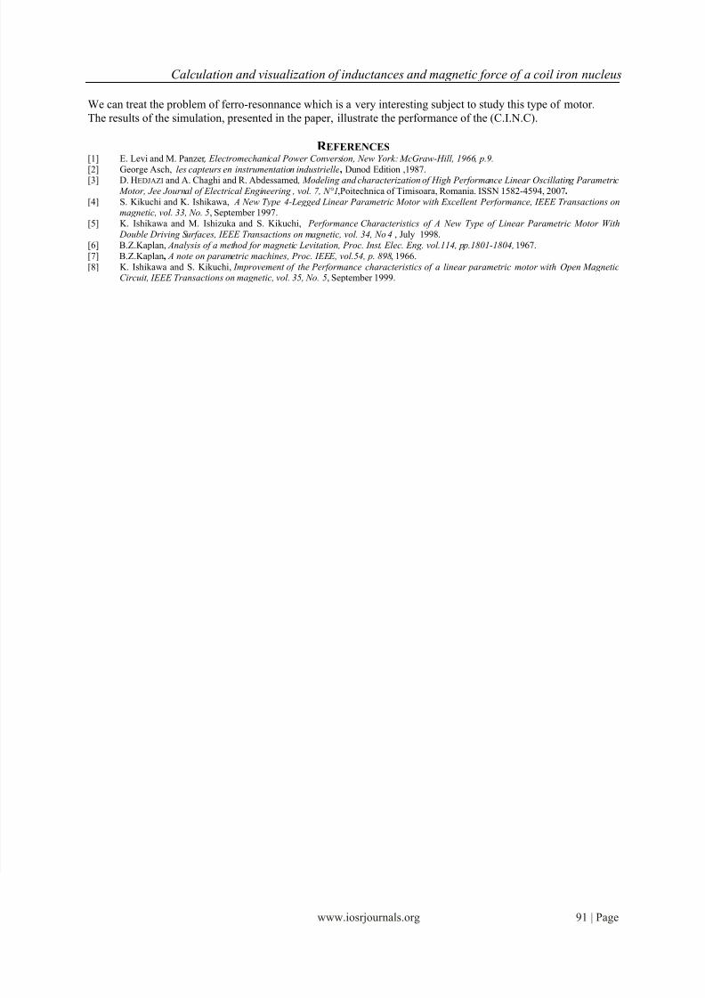
The curve FigVII.6 of the magnetic force given by the mathematical software (sigma plot9) used in ourresearch shows that it depends on the displacement x following the shape of the derivative of the inductance L,
which is a very delicate operation, so it is simply derived inductance: Fe = 0.5*i2
*( dL / dx).
FigVII.6 Variation of the force in function of (x)
VIII. CONCLUSION
The elaborate work have give a satisfactory results, the inductances determined can be exploit for any
eventual simulation of a tubular linear motor all we exploit the equations of KIRCHOFF in level of the inductor
(coil) and induces (nucleus) to model the (C.I.N.C) .
The object of our study is to determine the inductance of the motor linear oscillations (C.I.N.C) which
led eventually to easily find the magnetic force that governs the operation of the engine, We note also that here
the nucleus comes in the middle of the coil force changes direction and the ring returns to its original positioncausing the oscillation.
7/27/2019 Calculation and visualization of inductances and magnetic force of a coil iron nucleus
http://slidepdf.com/reader/full/calculation-and-visualization-of-inductances-and-magnetic-force-of-a-coil-iron 9/9
Calculation and visualization of inductances and magnetic force of a coil iron nucleus
www.iosrjournals.org 91 | Page
We can treat the problem of ferro-resonnance which is a very interesting subject to study this type of motor.
The results of the simulation, presented in the paper, illustrate the performance of the (C.I.N.C).
R EFERENCES[1] E. Levi and M. Panzer , Electromechanical Power Conversion, New York: McGraw-Hill, 1966, p.9.
[2] George Asch, les capteurs en instrumentation industrielle, Dunod Edition ,1987.[3] D. HEDJAZI and A. Chaghi and R. Abdessamed , Modeling and characterization of High Performance Linear Oscillating Parametric
Motor, Jee Journal of Electrical Engineering , vol. 7, N°1,Poitechnica of Timisoara, Romania. ISSN 1582-4594, 2007.
[4] S. Kikuchi and K. Ishikawa, A New Type 4-Legged Linear Parametric Motor with Excellent Performance, IEEE Transactions onmagnetic, vol. 33, No. 5, September 1997.
[5] K. Ishikawa and M. Ishizuka and S. Kikuchi, Performance Characteristics of A New Type of Linear Parametric Motor With
Double Driving Surfaces, IEEE Transactions on magnetic, vol. 34, No 4 , July 1998.
[6] B.Z.Kaplan, Analysis of a method for magnetic Levitation, Proc. Inst. Elec. Eng. vol.114, pp.1801-1804, 1967.
[7] B.Z.Kaplan, A note on parametric machines, Proc. IEEE, vol.54, p. 898, 1966.
[8] K. Ishikawa and S. Kikuchi, Improvement of the Performance characteristics of a linear parametric motor with Open MagneticCircuit, IEEE Transactions on magnetic, vol. 35, No. 5, September 1999.