Embed Size (px)
Citation preview

ENCLOSURE7
MONTICELLO NUCLEAR GENERATING PLANT
LICENSE AMENDMENT REQUEST
REVISE THE TECHNICAL SPECIFICATIONS TO INCLUDE A
PRESSURE TEMPERATURE LIMITS REPORT
CALCULATION CA 11-020
FINITE ELEMENT STRESS ANALYSIS OFMONTICELLO RPV RECIRCULATION INLET NOZZLE
(SIA No. 1000720.301)
(30 pages follow)

QF-0549 (FP-E-CAL-01), Rev. 7 Pa~qe 1 of 4
XcelEnergy Calculation Signature Sheet
Document Information
NSPM Calculation (Doc) No: 11-020 ý Revision: 0
Title: Finite Element Analysis of RPV Recirculation Inlet Nozzle
Facility: Z MT E]PI IPUnit: 2 1 E112Safety Class: Z SR El Aug Q [i Non SR
Special Codes: [] Safeguards El Proprietary
Type: Calc Sub-Type:
[NOTE: Print and sign name in signature blocks, as required. JMajor Revisions U[ N/A
EC Number: 17657 [ Vendor Calc
Vendor Name or Code: Structural Integrity Vendor Doc No: 1000720.301Associates (SIA)
Description of Revision: New Calculation Issuance
The following calculation and attachments have been reviewed and deemedacceptable as a legible QA recordPrepared by: (sign) /- / (print) SIA Date: 2/9/2011
Reviewed by:(sign) $•4/ (print) Wynter McGruder Date: 2/9/2011
Type of Review: ED )esign Verification [I Tech Review Z Suitability Review
Method Used (For DV Only): U] RevAZQAlternate Calc [] Test
Approved by: (sign) (prnt) Steve Kibler Date:a ? ...
Minor ,evisions I N/AEC No: El Vendor Calc:
Minor Rev. No:
Description of Change:
Pages Affected:Theacetalfollowinga calculationa lgbeQandreorattachments have been reviewed and deed El
Prepared by: (sign) / (print) Date:
Reviewed by: (sign) / (print) Date:
Type of Review: LI Design Verification EU Tech Review LI Suitability Review
Method Used (For DV Only): Ul Review El Alternate Calc n Test
Approved by: (sign) - /(print) . [ Date:
Record Retention: Retain this form with the associated calculation for the life of the plant.

This reference table is used for data entry into the PassPort Controlled Documents Module reference tables (C012 Panel). It mayNOTE: also be used as the reference section of the calculation. The input documents, output documents and other references should all be
listed here. Add additional lines as needed by using the "TAB" key and filling in the appropriate information in each column.
Reference Documents (PassPort C012 Panel from C020)
# Controlled* Document Name Document Doc Ref Type**Doc?+ Type Number Rev INPUT -OUTPUT
1 US Nuclear Regulatory Commission, Reactor Vessel Integrity N/A NIA XDatabase, Version 2.0.1
2 GE Stress Report No. 23A1 627, Revision 1, "Recirculation Inlet 23A1627 XNozzle,"
3 ASME Boiler and Pressure Vessel Code, Section III including N/A N/A XAppendices, 1980 Edition with Addenda through Winter 1980
4 CB&I Drawing No. 7, Revision 9, "12" Nozzle MK. A/K 17'-2" I.D. xx DRAW 63'-2" Ins. Heads Nuclear Reactor, Monticello Drawing NX-8290- 8290-90 9 X
90
5 GE Design Specification No. 25A5744, Revision 1, "Reactor 25A5744 1 XVessel-Power Rerate"
6 GE Design Specification No. 23A1581, Revision 3, "Reactor 23A1581 3 XVessel-Recirculation Inlet Safe End"
7 CB&I Stress Report, Section T8, "Thermal Analysis, Recirculation N/A N/A XInlet Nozzle, Monticello Reactor Pressure Vessel"
8 ANSYS Mechanical and PrepPost, Release 11.0 (w/Service Pack N/A N/A X1), ANSYS, Inc., August 2007
10
11
12
13
14
15 1
Record Retention: Retain this form with the associated calculation for the life of the plant.

QF-0549 (FP-E-CAL-01), Rev. 7 Page 3 of 4
XcelEnergy- Calculation Signature Sheet
116 1 1 I II17
Controlled Doc marked with an "X" means the reference can be entered on the C012 panel in black. Unmarked lines will be yellow. If marked with an "X", alsolist the Doc Type, e.g., CALC, DRAW, VTM, PROC, etc.Mark with an "X" if the calculation provides inputs and/or outputs or both. If not, leave blank. (Corresponds to PassPort "Ref Type" codes: Inputs I Both ="ICALO', Outputs = "OCALC", Other I Unknown = blank)
Other PassPort Data
Associated System (PassPort C011, first three columns) OR Equipment References (PassPort C025, all five columns):
Facility Unit System Equipment Type Equipment Number
MT 1 RPV
Superseded Calculations (PassPort C019):
Facility Calc Document Number Title
N/A N/A N/A
Description Codes - Optional (PassPort C018):
Code Description (optional) Code Description (optional)
Notes (Nts) - Optional (PassPort X293 from C020):
Topic Notes Text
Record Retention: Retain this form with the associated calculation for the life of the plant.
Calc Introduction D Copy directly from the calculation Intro Paragraph or [ See write-up below
El (Specify)
Record Retention: Retain this form with the associated calculation for the life of the plant.

Monticello Specific Information
YES13 YES
[] N/AEN/A
Topic Code(s) (See MT Form 3805): PLEX, RATEStructural Code(s) (See MT Form 3805):
Does the Galculatior0 YES Z No
n:
Require Fire Protection Review? (Using MT Form 3765, "Fire Protection Program Checklist", determine if aFire Protection Review is required.) If YES, document the engineering review in the EC. If NO, then attachcompleted MT Form 3765 to the associated EC.
Affect piping or supports? (If Yes, Attach MT Form 3544.)Affect IST Program Valve or Pump Reference Values, and/or Acceptance Criteria? (If Yes, inform IST
Coordinator and provide copy of calculation.)
13 YES13 YES
~No~No
Record Retention: Retain this form with the associated calculation for the life of the plant.
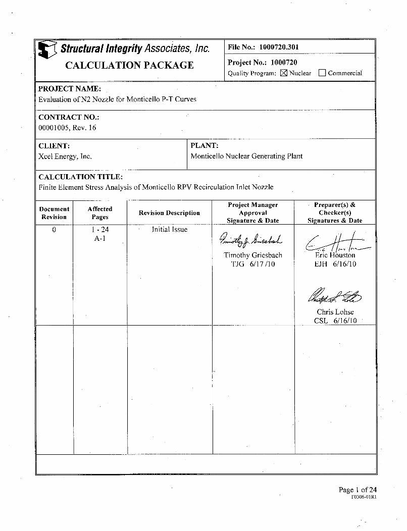
V Structural Integrity Associates, Inc. File No.: 1000720.301
CALCULATION PACKAGE Project No.: 1000720Quality Program: 0 Nuclear F] Commercial
PROJECT NAME:
Evaluation of N2 Nozzle for Monticello P-T Curves
CONTRACT NO.:
00001005, Rev. 16
CLIENT: PLANT:Xcet Energy, Inc. Monticello Nuclear Generating Plant
CALCULATION TITLE:Finite Element Stress Analysis of Monticello RPV Recirculation Inlet Nozzle
Document Affected Project Manager Preparer(s) &Documen afe Revision Description Approval Checker(s)Revision Pages Signature & Date Signatures & Date
0 1 - 24 Initial IssueA-I
Timothy Griesbach Eric HoustonTJG 6/17/10 EJH 6/16/10
Chris LohseCSL 6/16/10
Page 1 of 24F0306-O1R1

Structural Integrity Associates, Inc.
Table of Contents
1.0 O B JE C T IV E ................................................................................................................. 4
2.0 M ETH O D O LO G Y .... .............................................................................................. 4
3.0 D E SIG N IN P U TS ..................................................................................................... 4
4.0 A SSU M PT IO N S .............................................................................................................. 5
5.0 FINITE ELEMENT MODEL ................................................................................ 5
6.0 LOADS AND BOUNDARY CONDITIONS ......................................................... 6
7.0 RESULTS OF ANALYSIS ..................................................................................... 7
8.0 REFEREN CES ..................................................................................................... 8
APPENDIX A: LIST OF SUPPORTING FILES ........................................................... A-i
List of Tables
Table 1: RPV Material Properties (SA-533 Gr. B) ............................................................. 9
Table 2: Nozzle Material Properties (SA-508 Class II) ....................................................... 9
Table 3: Cladding Material Properties (Type 304 Stainless Steel) ........................................ 10
Table 4: Polynomial Coefficients for Unit Pressure Load Case .................... 10
Table 5: Polynomial Coefficients for Shutdown Transient Load Case, Path 1 ..... 11........... 1
Table 6: Polynomial Coefficients for Shutdown Transient Load Case, Path 2 .................. 13
File No.: 1000720.301Revision: 0
Page 2 of 24
F0306-O1RI
Structural Integrity Associates, Inc.
List of Figures
Figure 1: Finite Element Model Geometry ........................................................................ 15
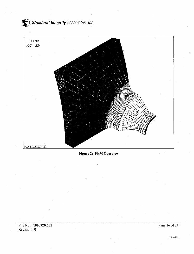
Figure 2: FEM Overview .................................................................................................. 16
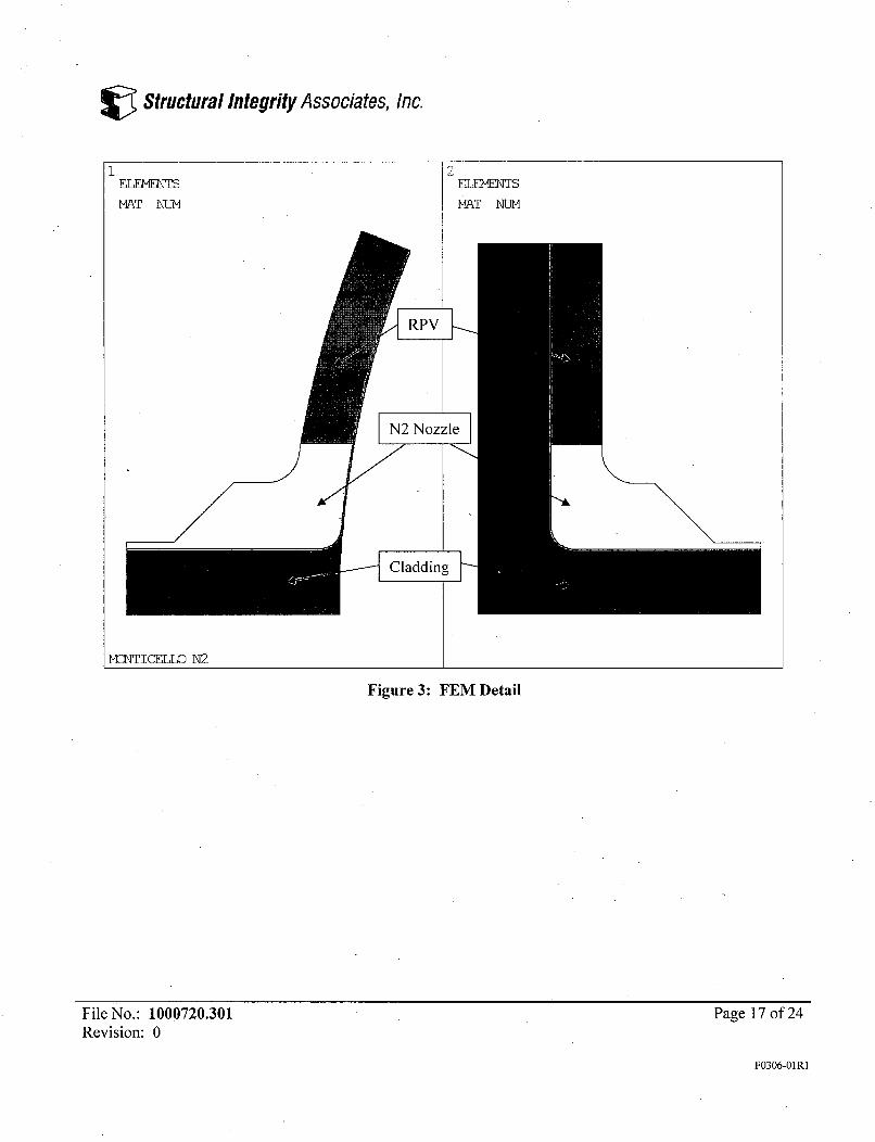
F igure 3: FE M D etail .............................................................................................................. 17
Figure 4: Unit Pressure Loading with Cap Loads ........................................................... 18
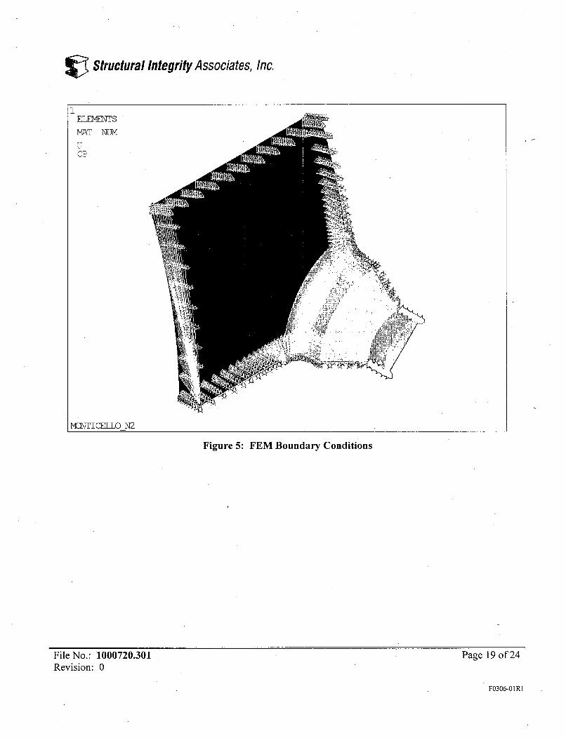
Figure 5: FEM Boundary Conditions ................................................................................ 19
Figure 6: FEM Convection Film Coefficients (Btu/sec-in2 -OF) ........................................ 20
Figure 7: Path 1 Location .................................................................................................. 21
Figure 8: Path 2 Location .................................................................................................. 22
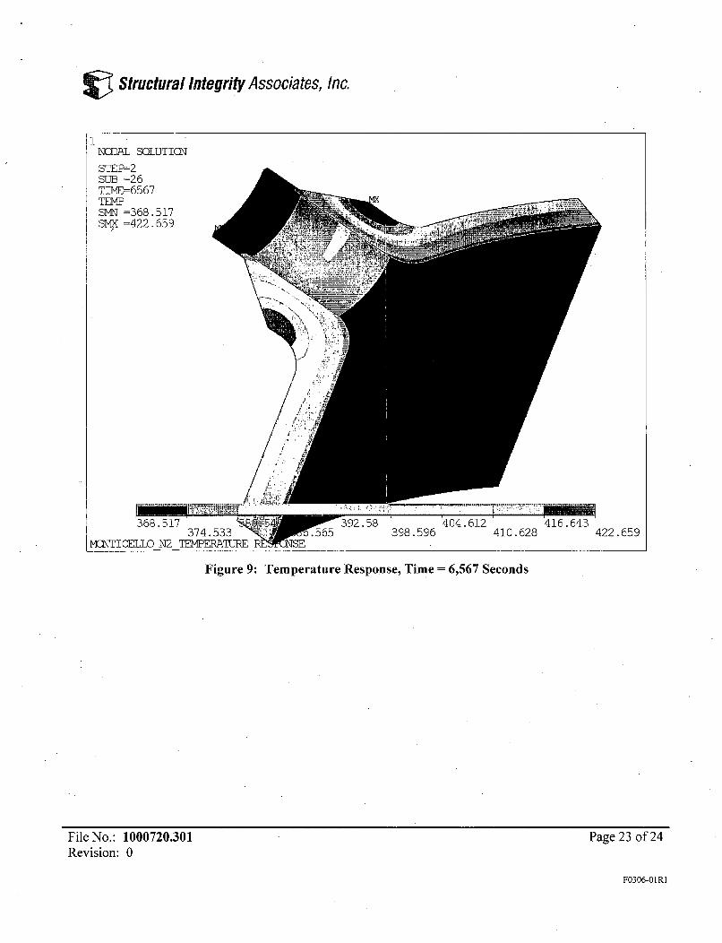
Figure 9: Temperature Response, Time = 6,567 Seconds ............................................... 23
Figure 10: Temperature Response, Time = 16,164 Seconds ............................................. 24
File No.: 1000720.301Revision: 0
Page 3 of 24
F0306-O1RI
Structural Integrity Associates, Inc.
1.0 OBJECTIVEThe objective of this calculation is to perform finite element stress analysis on the recirculation inlet(N2) nozzles, at Monticello Nuclear Generating Plant. Pressure-temperature (P-T) curves for the N2nozzles are to be generated using the results of this analysis.
2.0 METHODOLOGYA three-dimensional finite element model (FEM) is constructed for the recirculation inlet nozzle to beevaluated. The finite element model also includes a portion of the reactor pressure vessel (RPV) as wellas the internal cladding. The safe end, thermal sleeve and attached piping are not modeled since thesecomponents are far from the location of interest, which is the nozzle blend radius. A unit internalpressure load and applicable thermal transients are applied. Multiple paths through the nozzle blendradius are selected at different azimuths based on the maximum hoop stress at the inside surface of thenozzle, excluding the cladding. The hoop stress along these paths is curve fit with a 3rd orderpolynomial. For thermal transient loading, the polynomial coefficients are reported for all time steps.
3.0 DESIGN INPUTSThe following design inputs are used in this calculation:
* RPV material = SA-533 Gr. B [1]* N2 material = SA-508 C1 I [2]* Cladding (or overlay) material = Type 304 stainless steel { 1, §4.0}* N2 Design Code of Record [2, Sheet No. 2]= ASME Section III, 1980 Edition with.Addenda
through Winter 1980 [3]* Temperature dependent material properties are obtained from Reference [3] and are listed in
Tables 1 through 3* RPV and N2 geometry are taken from Reference [4] and reproduced in Figure 1* Maximum temperature under normal operating condition = 549°F [5, Section 4.4.3.1 .c]* Normal operating thermal transient applicable to N2 is heatup/cooldown [6, Figure 4; 7] {2,
§4.0):o Fluid initial steady state condition = 549°F [5]o Fluid final steady state condition = 100°Fo Fluid rate of change = -100°F per hour
* Heat transfer coefficients (see Figure 6 and Section 6.0 for application areas on the model)o Vessel region -heat transfer coefficient (Btu/hr-ft2 -°F) 87.8 AT' [7, p. I-T8-12]o Nozzle region heat transfer coefficient (Btu/hr-ft2 -•OF) 11.5 AT"" [7, p. I-T8-1 1]o Nozzle blend radius heat transfer coefficient = Vessel region heat transfer coefficient {4;
§4.01
File No.: 1000720.301 Page 4 of 24Revision: 0
F0306-O1R1
Structural Integrity Associates, Inc.
4.0 ASSUMPTIONSThe assumptions made in order to define the evaluation approach and perform the analysis aresummarized in the following list. The application of these assumptions is indicated throughout thedocument using a set of braces containing the appropriate assumption number; for example, Assumption#1 would be indicated as {1, §4.0}.
1. RPV and N2 nozzle cladding material is assumed to be Type 304 stainless steel. Note thatReference [4] refers to the cladding as "overlay."
2. Reference [6] defines both the heatup and cooldown transient. However, the cooldown transienttypically produces more severe hoop stress at the inner surface of the nozzle and vessel. Becausethe analysis will be used in generating pressure-temperature limit curves, the location of interestis near the inner surface of the nozzle blend radius. Therefore, the analysis is run only for thecooldown transient. The cooldown transient has the following characteristics:
a. The maximum temperature under normal operating conditions in [6, Figure 4] is modifiedby Reference [5] to 549°F.
b. The heat transfer coefficients in [7] for heatup are assumed applicable to cooldown.
3. The effect of the thermal sleeve is conservatively ignored when determining the fluidtemperature boundary condition at the nozzle inner surface. That is, the stagnant region isconservatively assumed to have bulk fluid temperature present. This results in more rapidcooling of the nozzle blend radius, which in turn increases the thermal gradient from the outer tothe inner surface of the blend radius. The increased thermal gradient increases the hoop stressesin the blend radius.
4. The nozzle blend radius heat transfer coefficient uses the maximum of the vessel and nozzle heattransfer coefficients, which are calculated using guidance from Reference [7]. The full delta T ofthe transient is used in calculating the heat transfer coefficients. Therefore, the vessel region heattransfer coefficient is the bounding, or maximum, heat transfer coefficient.
5. All external surfaces are conservatively assumed to be insulated. No thermal boundaryconditions are specified for these locations, which results in adiabatic boundaries.
6. Density is assumed constant at 0.283 lb/in3 and Poison's ratio is assumed constant at 0.3.
5.0 FINITE ELEMENT MODELThe three-dimensional (3-D) finite element model is developed for the N2 nozzle using the ANSYSfinite element software package [8] using 8-node SOLID45 3-D linear structural elements. Thedimensions used for the nozzle and RPV shell are provided in Reference [4]. In order to reduce thecomplexity of the FEM, some features remote from the area of interest are not modeled. This includesthe safe end, safe end-to-nozzle weld (including overlay shown in [2, Section 30.3.2]), thermal sleeve
File No.: 1000720.301 Page 5 of 24Revision: 0
F0306-OIR1

Structural Integrity Associates, Inc.
and some radii (which are modeled as points). The dimensions used in the model are presented in Figure1.
The one-quarter 3D model extends the end of the machined portion of the nozzle a total of 5 inches,while the RPV shell extends 22.20 circumferentially and 40 inches axially from the nozzle axis. Thesedimensions are large enough such that boundary conditions do not introduce non-representative effectsin the FEA solution at the nozzle blend radius region. The finite element model is shown in Figures 2and3. The ANSYS input files used to generate the FEM are included with the electronic supportingfiles listed in Appendix A.
6.0 LOADS AND BOUNDARY CONDITIONSTwo load conditions, one steady state and one transient, are applied to the FEM. The steady state load isa unit pressure case of 1,000 psig. The transient is normal shutdown {2, §4.0} and is described inSection 3.0.
For the unit pressure case, a uniform pressure of 1,000 psig is applied to the inside surface of the RPVand nozzle bore. Note that the cladding is not included in the unit pressure anfalysis. A cap load, Pcll, isapplied to the upper horizontal cut plane in the model, which is calculated as:
p - PuIJRveP R,, - s -IRs
where:Punijt unit pressure, psigIRves = inside radius of RPV excluding cladding, inORves = outside radius of RPV, in.
A cap load, Pc12, is also applied to the free end of the nozzle, which is calculated as:
P11l2 - o 2 _i 2
where:IRnoz = inside radius of nozzle excluding cladding, inOMnoz = outside radius of nozzle free end, in.
Symmetry boundary conditions are applied on both of the vertical cut planes. The lower horizontal cutplane in the 3-D model is fixed in the axial degree of freedom. The nodes at the free end of the nozzleare coupled in the axial direction, as are the RPV nodes on the upper horizontal cut plane. The unitpressure loads and boundary conditions are shown in Figures 4 and 5, respectively. The ANSYS inputfile for the unit load is included with the electronic supporting files listed in Appendix A.
For the transient case, heat transfer coefficients for the RPV and nozzle are calculated from the equationsin Section 3.0. The full temperature difference of 449°F (maximum under normal operating condition -ambient) is conservatively used in calculating the heat transfer coefficients {4, §4.0}. Bounding heat
File No.: 1000720.301 Page'6 of 24Revision: 0
F0306-OIR1
Structural Integrity Associates, Inc.
transfer coefficients of 265 and 675 Btu/hr-ft2 -F for the nozzle and vessel region, respectively, are usedin the analysis. The larger of the two values is used for the nozzle blend radius {4, §4.0}. All externalsurfaces are conservatively assumed to be perfectly insulated {5, §4.0}. The bulk fluid temperature isconservatively assumed to act on all internal surfaces {3, §4.0}. Note that the calculated heat transfercoefficients bound the maximum values for the nozzle [2, Section 4.2.2] and vessel [2, Section 4.2.4.4]given in more recent analysis and areconservatively used in the analysis herein. Figure 6 shows the heattransfer coefficients applied to the FEM.
The thermal boundary conditions are applied to the surface of the cladding. However, the stresses due tothe thermal gradient are calculated without taking credit for this additional thickness. The ANSYS inputfiles used to generate the thermal stresses are included with the electronic supporting files listed inAppendix A.
7.0 RESULTS OF ANALYSISAfter running the unit pressure load case, the nodes along the blend radius at both cut planes are queriedfor the location of maximum hoop stress. A path is defined for each cut plane that includes thismaximum location and the hoop stress is extracted along these paths. Figures 7 and 8 show the pathlocations. The transient load case is run, and the hoop stress is extracted (along the same paths used forpressure stress extraction) for all time steps. The temperature response is shown in Figures 9 and 10 forselected times.
The hoop stress is curve fit with a 3 rd order polynomial. The coefficients are presented in Tables 4through 6 and are included in the .csv files included with the electronic supporting files listed inAppendix A. The ANSYS stress extraction files are included with the electronic supporting files listedin Appendix A.
File No.: 1000720.301Revision: 0
Page 7 of 24
F0306-O1R1
Structural Integrity Associates, Inc.
8.0 REFERENCES
1. US Nuclear Regulatory Commission, Reactor Vessel Integrity Database, Version 2.0.1.
2. GE Stress Report No. 23A 1627, Revision 1, "Recirculation Inlet Nozzle," SI File No. MONT-14Q-211.
3. ASME Boiler and Pressure Vessel Code, Section III including Appendices, 1980 Edition withAddenda through Winter 1980.
4. CB&I Drawing No. 7, Revision 9, "12"0 Nozzle MK. N2 A/K 17'-2" I.D. x 63'-2" Ins. HeadsNuclear Reactor," Monticello Document No. NX-8920-90, SI File No. 1000720.201.
5. GE Certified Design Specification No. 25A5744, Revision 1, "Reactor Vessel - Power Rerate,"SI File No. XCEL-05Q-212.
6. GE Design Specification No. 23A1581, Revision 3, "Reactor Vessel - Recirculation Inlet SafeEnd," SI File No. 1000720.202.
7. CB&I Stress Report, Section T8, "Thermal Analysis, Recirculation Inlet Nozzle, MonticelloReactor Pressure Vessel," SI File No. MONT-14Q-202.
8. ANSYS Mechanical and PrepPost, Release 11.0 (w/ Service Pack 1), ANSYS, Inc., August2007.
File No.: 1000720.301Revision: 0
Page 8 of 24
F0306-OIRI
V Structural Integrity Associates, Inc.
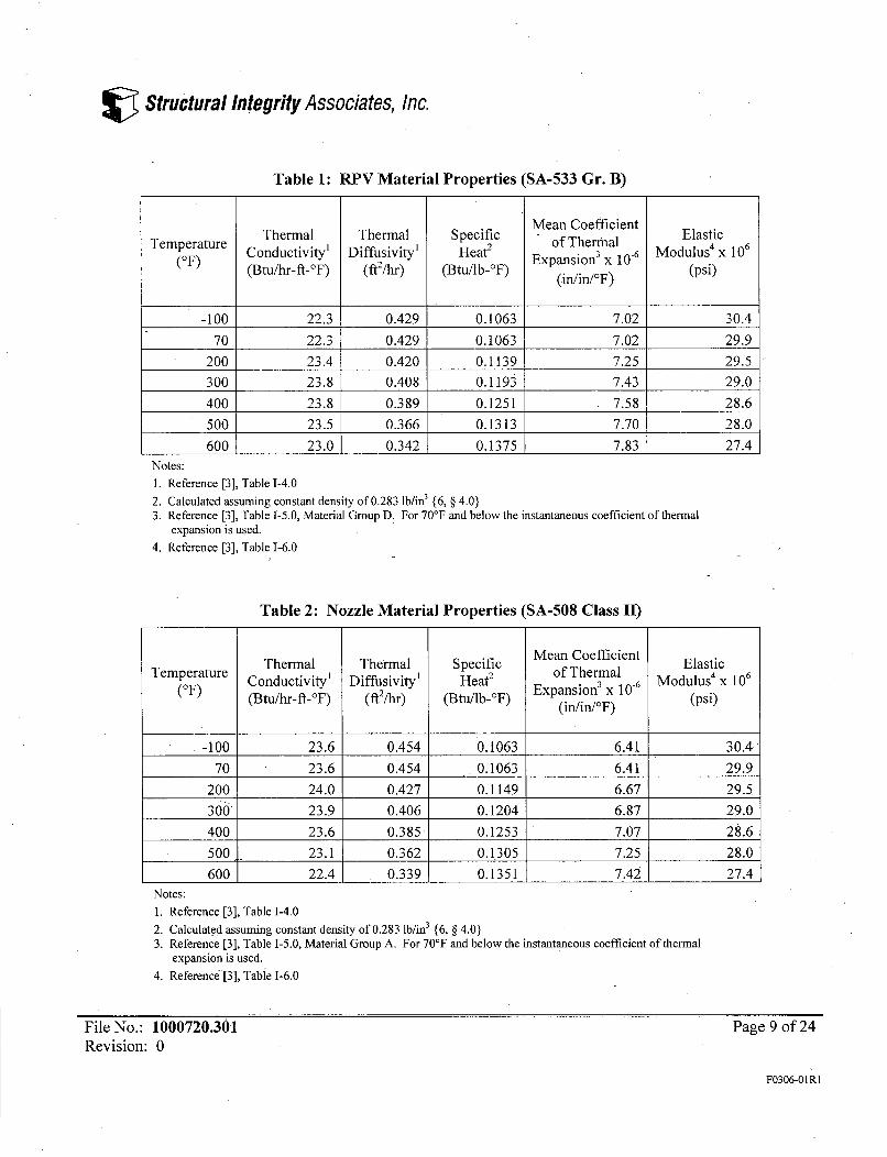
Table 1: RPV Material Properties (SA-533 Gr. B)
Mean CoefficientThermal Thermal Specific - Elastic
(OF) Conductivity' Diffusivityl Heat2 Expansiono 3 X 10T6 Modulu(Btu/hr-fi-°F) (ftZ/hr) (Btu/lb-°F) (in/in/xF) (psi)
-100 22.3 0.429 0.1063 7.02 30.4
70 22.3 0.429 0.1063 7.02 29.9
200 23.4 0.420 0.1139 7.25 29.5
300 23.8 0.408 0.1193 7.43 29.0
400 23.8 0.389 0.1251 7.58 28.6
500 23.5 0.366 0.1313 7.70 28.0
600 23.0 0.342 0.1375 7.83 27.4Notes:1. Reference [3], Table 1-4.02. Calculated assuming constant density of 0.283 lb/in3 {6, § 4.0)3. Reference [3], Table 1-5.0, Material Group D. For 70'F and below the instantaneous coefficient of thermal
expansion is used.4. Reference [3], Table 1-6.0
Table 2: Nozzle Material Properties (SA-508 Class II)
Thermal Thermal Specific Mean Coefficient Elastic(OFu Conductivity' Diffusivity' Heat2 Moduluof T he0(°F) (Btu/hr-ft-_F) (ft2/hr) (Btu/lb-_F) Expansion 3 X 10.6s(in/in/OF) (psi)
-100 23.6 0.454 0.1063 6.41 30.470 23.6 0.454 0.1063 6.41 29.9
200 24.0 0.427 0.1149 6.67 29.5
300) 23.9 0.406 0.1204 6.87 29.0
400 23.6 0.385 0.1253 7.07 28.6
500 23.1 0.362 0.1305 7.25 28.0
600 22.4 0.339 0.1351 7.42 27.4Notes:1. Reference [3], Table 1-4.02. Calculated assuming constant density of 0.283 lb/in3 {6, § 4.0)3. Reference [3], Table 1-5.0, Material Group A. For 70'F and below the instantaneous coefficient of thermal
expansion is used.4. Reference-[3], Table 1-6.0
File No.: 1000720.301Revision: 0
Page 9 of 24
F0306-OIR1

V Structural Integrity Associates, Inc.
Table 3: Cladding Material Properties (Type 304 Stainless Steel)
Thermal Thermal Specific Mean Coefficient ElasticTemperature Conductivity' Diffusivityl Heat2 Modulus4 X(OF) (Btu/hr-ft-_F) (ft2/hr) (Btu/Ilb-F) Expansion' X 10 (psi)
(in/in/OF)
-100 8.6 0.151 0.1165 7.93 29.4
70 8.6 0.151 0.1165 7.93 28.3
200 9.3 0.156 0.1219 8.37 27.7
300 9.8 0.160 0.1252 8.70 27.1
400 10.4 0.165 0.1289 8.97 26.6
500 10.9 0.170 0.1311 9.23 26.1
600 11.3 0.174 0.1328 9.42 25.4Notes:1. Reference [3], Table 1-4.02. Calculated assuming constant density of 0.283 lb/in3 {6, § 4.0}3. Reference [3], Table 1-5.0. For 70'F and below the instantaneous coefficient of thermal expansion is used.4. Reference [3], Table 1-6.0
Table 4: Polynomial Coefficients for Unit Pressure Load Case
Path CO C1 - C2 C3
1 49213.37 -10902.90 1312.79 -69.57
2 14173.12 -811.72 -65.35 18.81
FileNo.: 1000720.301Revision: 0
Page 10 of 24
F0306-OIR1

V Structural Integrity Associates, Inc.
Table 5: Polynomial Coefficients for Shutdown Transient Load Case, Path 1
Time (sec) CO Cl C2 C31 -6722.08 8696.04 -1912.93 116.83
254 -5531.75 7947.40 -1793.43 110.78506 -4346.28 7318.64 -1709.45 107.12759 -3307.22 6822.85 -1651.66 104.93
1011 -2418.18 6418.89 -1607.81 103.39
1264 -1660.09 6076.91 -1571.06 102.111516 -1013.77 5779.70 -1538.20 100.901769 -460.83 5515.83 -1507.48 99.71
2021 21.38 5271.41 -1476.63 98.39
2274 462.89 5027.22 -1442.28 96.772526 850.85 4800.84 -1408.83 95.132779 1191.14 4593.47 -1377.07 93.553032 1490.50 4402.57 -1346.67 91.98
3284 1756.12 4222.81 -1316.43 90.363537 1994.29 4049.00 -1285.52 88.643789 2208.44 3883.19 -1255.06 86.934042 2402.20 3724.10 -1224.84 85.194294 2578.78 3570.67 -1194.84 83.454547 2740.49 3422.22 -1165.03 81.69
4799 2889.54 3278.02 -1135.41 79.935052 3027.71 3137.56 -1105.96 78.155304 3156.48 3000.29 -1076.66 76.385557 3277.22 2865.73 -1047.50 74.605810 3396.17 2729.05 -1017.50 72.76
6062 3514.35 2590.69 -987.03 70.886315 3626.38 2457.02 -957.63 69.086567 3727.94 2331.85 -930.11 67.406820 3814.07 2215.50 -904.03 65.807072" 3891.92 2099.85 -877.09 64.097325 3969.13 1979.51 -848.68 62.29
7577 4043.46 1860.99 -820.78 60.547830 4115.59 1743.34 -792.98 58.788083 4185.63 1626.56 -765.29 57.048335 4253.77 1510.50 -737.70 55.298588 4320.05 1395.16 -710.20 53.558840 4384.58 1280.47 -682.79 51.82
9093 4447.38 1166.46 -655.49 50.099345 4514.89 1047.52 -627.10 48.29
9598 4585.64 924.71 -597.89 46.459850 4653.43 802.99 -568.91 44.61
10103 4718.14 682.45 -540.16 42.80
10355 4777.90 563.53 -511.66 41.0010608 4835.19 446.06 -483.49 39.2210861 4891.19 330.05 -455.65 37.46
11113 4946.07 215.02 -428.00 35.7211366 4999.59 101.07 -400.58 33.9811618 5051.74 -11.92 -373.35 32.2611871 5102.55 -123.91 -346.34 30.5512123 5151.88 -234.89 -319.53 28.86
12376 5199.72 -344.84 -292.93 27.1812628 5246.15 -453.89 -266.52 25.5012881 5291.13 -561.95 -240.31 23.8513133 5333.52 -668.39 -214.40 22.20
13386 5374.00 -774.05 -188.59 20.5713639 5414.28 -880.18 -162.64 18.92
13891 5454.30 -986.08 -136.79 17.28
14144 5493.21 -1090.68 -111.28 15.67
File No.: 1000720.301Revision: 0
Page 11 of 24
F0306-0IRI

V Structural Integrity Associates, Inc.
Time (sec) . CO C1 C2 C314396 5530.64 -1193.71 -86.15 14.08
14649 5566.23 -1295.23 -61.33 12.51
14901 5600.19 -1395.47 -36.77 10.9515154 5632.42 -1494.40 -12.49 9.4115406 5662.90 -1592.05 11.52 7.89
15659 5691.63 -1688.48 35.28 6.38
15911 5718.61 -1783.64 58.77 4.8916164 5743.72 -1877.50 81.99 3.4216202 5639.01 -1805.17 68.89 4.1516241 5492.42 -1708.29 52.31 5.03
16356 4992.41 -1433.42 13.29 6.82
16701 3749.82 -911.66 -36.90 8.2017085 2714.93 -538.48 -61.41 8.2517468 1950.48 -281.31 -74.02 7.9417852 1387.31 -96.61 -81.55 7.58
18235 972.25 38.97 -86.53 7.2618619 665.99 139.59 -90.03 7.00
19003 439.73 214.67 -92.55 6.7919386 272.34 270.87 -94.41 6.6319770 148.33 313.01 -95.78 6.5020000 86.80 334.10 -96.46 6.44
File No.: 1000720.301Revision: 0
Page 12 of 24
F0306-01RI
Structural Integrity Associates, Inc.
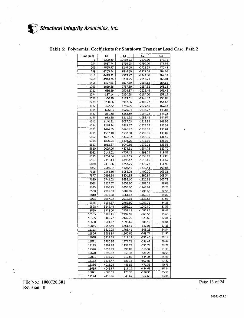
Table 6: Polynomial Coefficients for Shutdown Transient Load Case, Path 2
Time (sec) CO Cl C2 C31 -6200.89 10439.62 -2600.90 179.75-
254 -5087:74 9760.55 -2490.00 173.62
506 -4060.97 9240.06 -2422.53 170.48
759 -3205.24 8844.50 -2378.54 168.691011 -2499.22 8523.97 -2344.30 167.331264 -1914.76 8250.25 -2313.73 166.041516 -1427.61 8007.39 -2284.12 164.661769 -1019.86 7787.39 -2254.62 163.18
2021 -666.29 7574.87 -2222.46 161.42
2274 -337.14 7350.53 -2184.00 159.152526 -50.29 7139.61 -2146.07 156.882779 200.06 6942.86 -2109.27 154.63
3032 422.32 6755.95 -2072.55 152.333284 626.03 6570.24 -2033.77 149.81
3537 811.60 6388.89 -1994.73 147.25
3789 982.60 6211.28 -1955.43 144.644042 1140.81 6037.03 -1915.89 141.994294 1288.24 5865.67 -1876.17 139.31
4547 1426.65 5696.82 -1836.32 136.61
4799 1557.40 5530.08 -1796.36 133.87
5052 1681.55 5365.32 -1756.35 131.125304 1800.04 5202.25 -1716.30 128.365557 1913.67 5040.56 -1676.21 125.58
5810 2029.06 4874.51 -1634.78 122.706062 2145.02 4707.48 -1593.22 119.82
6315 2254.04 4547.65 -1553.63 117.096567 2351.13 4398.12 -1516.46 114.52
6820 2431.66 4253.25 -1479.27 111.90
7072 2510.07 4102.41 -1439.51 109.087325 2588.36 3952.02 -1400.20 106.317577 2666.64 3801.65 -1360.94 103.54
7830 2743.03 3652.10 -1321.81 100.798083 2817.57 3503.30 -1282.79 98.03
8335 2890.25 3355.20 -1243.87 95.298588 2961.03 3207.85 -1205.08 92.558840 3029.98 3061.12 -1166.38 89.82
9093 3097.02 2915.16 -1127.83 87.099345 3169.57 2762.80 -1087.71 84.269598 3245.44 2606.21 -1046.60 81.36
9850 3318.00 2451.15 -1005.85 78.4810103 3386.15 2297.91 -965.50 75.63
10355 3445.77 2147.25 -925.60 72.8110608 3501.87 1998.65 -886.19 70.0410861 3556.69 1851.41 -847.08 67.28
11113 3610.05 1705.41 -808.25 64.5411366 3661.94 1560.66 -769.71 61.8211618 3712.23 1417.13 -731.45 59.12
11871 3760.90 1274.78 -693.47 56.44
12123 3807.78 1133.72 -655.78 53.77
12376 3852.89 993.89 -618.37 51.1312628 3896.12 855.37 -581.26 48.51
12881 3937.75 717.85 -544.38 45.90
13133 3976.47 582.16 -507.87 43.32
13386 4013.29 446.86 -471.33 40.73
13639 4049.87 311.16 -434.69 38.1413891 4085.75 176.35 -398.36 35.5714144 4119.86 43.67 -362.63 33.05
File No.: 1000720.301Revision: 0
Page 13 of 24
F0306-O1R1
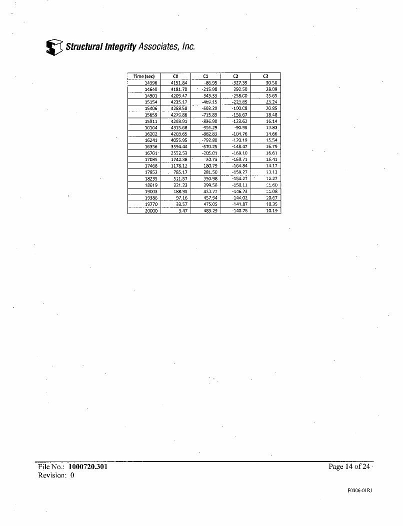
V Structural Integrity Associates, Inc.
lime (sec) CO Cl C2 C3
14396 4151.84 -86.95 -327.39 30.5614649 4181.70 -215.98 -292.50 28.09
14901 4209.47 -343.33 -258.00 25.6515154 4235.17 -469.15 -223.85 23.24
15406 4258.58 -593.29 -190.08 20.85
15659 4279.86 -715.89 -156.67 18.4815911 4298.91 -836.90 -123.62 16.1416164 4315.68 -956.29 -90.95 13.8316202 4203.65 -882.83 -104.76 14.6616241 4055.95 -792.80 -120.19 15.54
16356 3594.44 -570.25 -148.47 16.7916701- 2552.53 -205.01 -169.10 16.6117085 1742.38 30.75 -169.71 15.4117468 1178.12 180.79 -164.84 14.1717852 785.17 281.50 -159.27 13.12
18235 511.57 350.98 -154.27 12.27
18619 321.23 399.56 -150.11 11.6019003 188.95 433.77 -146.73 11.0819386 97.16 457.94 -144.02 10.6719770 33.57 475.05 -141.87 10.35
20000 3.47 483.29 -140.76 10.19
File No.: 1000720.301Revision: 0
Page 14 of 24
F0306-OIR1

V Structural Integrity Associates, Inc.
(To Base Metal)
- 5.4375 "
-4-. .1875
R103.1875(To Base Meta-,""
R3.5"5.625
5.018.25
14.125
(To
R7.0625(To Base Metal)
-LNotes:1. Dimensions from Reference [4].2. Units in inches.
Figure 1: Finite Element Model Geometry
I I
File No.: 1000720.301Revision: 0
Page 15 of 24
F0306-O1R1
V Structural Integrity Associates, Inc.
1
HAT NUM
,-TZT C"llO N2
Figure 2: FEM Overview
File No.: 1000720.301Revision' 0
Page 16 of 24
F0306-OIR1
V Structural Integrity Associates, Inc.
Figure 3: FEM Detail
File No.: 1000720.301Revision: 0
Page 17 of 24
F0306-O1RI

V Structural Integrity Associates, Inc.
1FJIZES
MAT NUM
PRES-NOP-
-9245 -6968 -4692 -2415 -138.325-8107 -5830 -3553 -1277 1000
MINTICKLIQ N2
Figure 4: Unit Pressure Loading with Cap Loads
File No.: 1000720.301Revision: 0
Page 18 of 24
F0306-OIRI
V Structural Integrity Associates, Inc.
ELE=ENSHAT NUM
MC•£TICeEL=O N2
Figure 5: FEM Boundary Conditions
File No.: 1000720.301Revision: 0
Page 19 of 24
F0306-O1RI

V Structural Integrity Associates, Inc.
1ELEMENTS
MAT NUM
aVw-HWE
.511E-03
MONTICELLO N2.001302
Figure 6: FEM Convection Film Coefficients (Btu/sec-in2-IF)
File No.: 1000720.301Revision: 0
Page 20 of 24
F0306-OIR1

V Structural Integrity Associates, Inc.
1
MAT NUM
MWTICET•O N2
Figure 7: Path 1 Location
File No.: 1000720.301Revision: 0
Page 21 of 24
F0306-OIR1

V Structural Integrity Associates, Inc.
Figure 8: Path 2 Location
File No.: 1000720.301Revision: 0
Page 22 of 24
F0306-OIR1
V Structural Integrity Associates, Inc.
1NODAL SOLUTICN
STEP=2SUB =26TIME=6567TEMPSHN =368.517SMX =422.659
Figure 9: Temperature Response, Time = 6,567 Seconds.
File No.: 1000720.301Revision: 0
Page 23 of 24
F0306-01R1
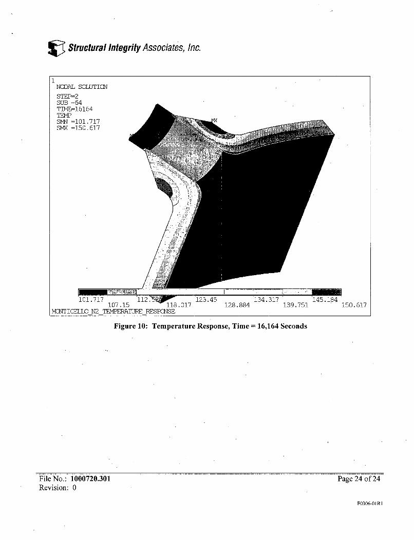
V Structural Integrity Associates, Inc.
1NCDAL SOLUTICM
STEP=2SUB =64TIME=16164
SW =101.717SMX =150.617
107.15 118.017 128.884 139.751 150.617MaqTTCF=1 N2 =ERPEA=TP RESPCSE
Figure 10: Temperature Response, Time = 16,164 Seconds
File No.: 1000720.301Revision: 0
Page 24 of 24
F0306-O1RI
Structural Integrity Associates, Inc.
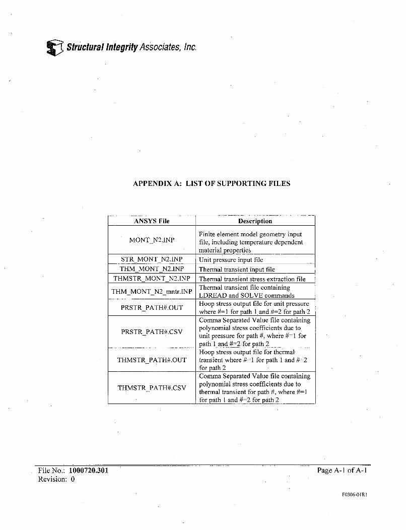
APPENDIX A: LIST OF SUPPORTING FILES
ANSYS File Description
Finite element model geometry inputMONTN2.JNP file, including temperature dependent
material propertiesSTRMONTN2.INP Unit pressure input file
THMMONTN2.1NP Thermal transient input file
THMSTRMONTN2.INP Thermal transient stress extraction fileTHM MONT N2-mntr.lNP Thermal transient file containing
T Nr LDREAD and SOLVE commandsPRSTRPATH#.OUT Hoop stress output file for unit pressure
- where #=1 for path land #=2 for path2Comma Separated Value file containing
PRSTR PATH#.CSV polynomial stress coefficients due toT A S unit pressure for path #, where #=1 for
path 1 and #=2 for path 2Hoop stress output file for thermal
THMSTRPATH#.OUT transient where #=1 for path 1 and #=2for path 2Comma Separated Value file containing
THMSTR PATH#.CSV polynomial stress coefficients due to- thermal transient for path #, where #=1
for path 1 and #=2 for path 2
File No.: 1000720.301Revision: 0
Page A- I of A- I
F0306-OIRI