Embed Size (px)
Citation preview
Calculation methods for column shoe
connections
TR 068
September 2018
EOTA TR 068 2/18
©EOTA 2018
EOTA Technical Reports are developed as supporting reference documents to EOTA publications such as European Technical Approval Guidelines (ETAG) and European Assessment Documents (EAD), or other harmonised technical specifications. They can be used for technical assessments of construction products, notably when conducted by Technical Assessment Bodies (TAB) designated by European Members States in accordance to Regulation (EU) No. 305/2011 for issuing European Technical Assessments (ETA). EOTA Technical Reports detail aspects relevant for construction products such as design, execution and evaluation of tests, and express the common understanding of existing knowledge and experience of the Technical Assessment Bodies in EOTA at a particular point in time. They may give recommendations for product packaging, transport, storage, maintenance, replacement and repair. Where knowledge and experience is developing, especially through assessment work, such reports can be amended. Amendments of EOTA Technical Reports supersede the previous one. The reference title and language for this TR is English. The applicable rules of copyright refer to the document elaborated in and published by EOTA. This EOTA Technical Report has been elaborated by EOTA WG 20 - Structural Metallic Products and Ancillaries; convened by VTT and has been adopted by the EOTA Technical Board.
EOTA TR 068 3/18
©EOTA 2018
Contents
1 Scope of the TR ..............................................................................................................................4
2 Specific terms/symbols used in this TR .......................................................................................5
List of Symbols 6
3 Design of column shoes and coluMn shoe connections in normal temperature ....................8
General 8
Design rules for mechanical resistance and bending stiffness of connection 8 3.2.1 Position of column shoes and design of connected structures .....................................................8 3.2.2 Mechanical resistance of column shoes in Stage I .......................................................................9
Mechanical resistance of column shoes in Stage II 10 3.3.1 General ...................................................................................................................................... 10 3.3.2 Design criterion for grouted section subjected to axial force and bending ............................... 11 3.3.3 Resistance of column end ......................................................................................................... 11 3.3.4 Interaction of axial force, bending moment and shear force ..................................................... 12
Resistance of column shoe components and welds 14
4 Fire resistance of column shoes without cover ....................................................................... 15
Temperature analysis 15
Fire rating based on temperature analysis 16
5 Analysis report ............................................................................................................................. 17
6 Reference documents ................................................................................................................. 18
EOTA TR 068 4/18
©EOTA 2018
1 SCOPE OF THE TR
This Technical Report (TR) covers the structural requirements and design rules for column shoe connections with column shoes in three stages: column shoe as delivered, column shoe connection before grouting and column shoe connection in use after grouting. This Technical Report (TR) can be used as criteria for assessing the performance and as design rules for column connections with column shoes. This TR does not purport to address all of the safety concerns associated with its use. It is the responsibility of the user of this technical report to establish appropriate safety practices and determine the applicability of regulatory limitations prior to use.
EOTA TR 068 5/18
©EOTA 2018
2 SPECIFIC TERMS/SYMBOLS USED IN THIS TR
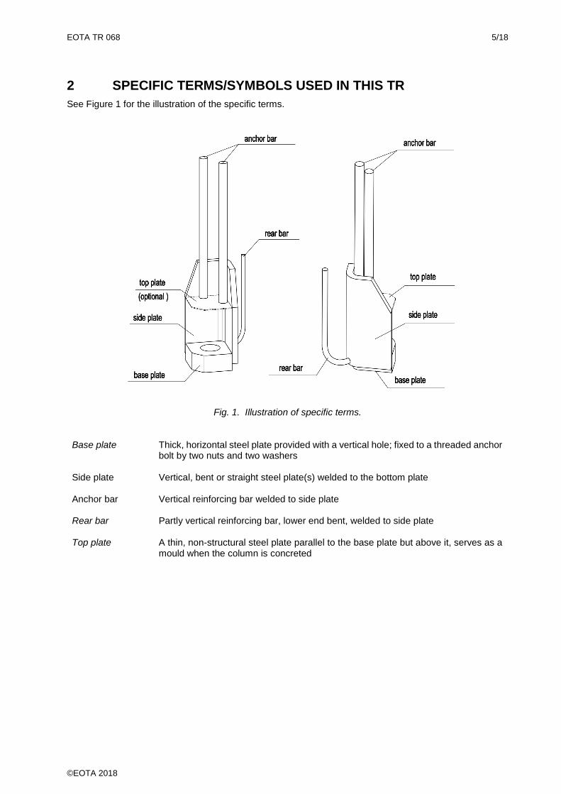
See Figure 1 for the illustration of the specific terms.
Fig. 1. Illustration of specific terms. Base plate Thick, horizontal steel plate provided with a vertical hole; fixed to a threaded anchor
bolt by two nuts and two washers
Side plate Vertical, bent or straight steel plate(s) welded to the bottom plate
Anchor bar Vertical reinforcing bar welded to side plate
Rear bar Partly vertical reinforcing bar, lower end bent, welded to side plate
Top plate A thin, non-structural steel plate parallel to the base plate but above it, serves as a mould when the column is concreted
EOTA TR 068 6/18
©EOTA 2018
List of Symbols
Aanc,i nominal cross-sectional area of anchor bar i
boltA tensile stress area of anchor bolt
i,plateA nominal cross-sectional area of side plate i
Fw,I the nominal resistance of the weld joint i Leff effective length to be used instead of l0 when designing the column with column shoes in
accordance with EN 1992-1-1:2004
Llap lap length
EdM design value of bending moment (action effect)
tM theoretical yielding moment of column shoe connection
ancN sum of nominal axial resistances of straight anchor bars
weld,ancN sum of calculated nominal resistances of welds between straight anchor bars and side
plate(s) in the direction of anchor bolt
nom,boltN nominal axial resistance of anchor bolt
weld,sideN sum of calculated nominal resistances of welds between the side plate(s) and base plate in
the direction of the anchor bolt
EdN design value of axial load on connection
1
EdN design value of axial load on a single bolt or column shoe
plateN sum of nominal axial resistances of side plates
RdN design value of axial resistance of column shoe and corresponding anchor bolt
P point load
V shear force
EdV design value of shear load on a connection
1
EdV design value of shear load on a single bolt or column shoe
RdV design value of shear resistance of a column shoe
ab coefficient calculated as in EN 1993-1-8, table 3.4
db diameter of nominal stress area in thread of anchor bolt
fanc,y,i yield strength of anchor bar i
fbase,u ultimate strength of base plate
fbolt,u ultimate strength of anchor bolt
fbolt,y yield strength of anchor bolt
fplate,y,i nominal yield strength of side plate i
fbolt,yd design yield strength of anchor bolt, used for design of column shoe connection
hnut thickness of nut below base plate
k1 coefficient calculated as in EN 1993-1-8, table 3.4
kL experimental factor:
- if kL ≤ 1,10, kLl0 gives the effective length to be used instead of l0 when designing the
columns in accordance with EN 1992-1-1
EOTA TR 068 7/18
©EOTA 2018
- if kL > 1,10, the connection is assumed to be hinged in design and effective length l0 specified in
EN 1992-1-1 is used as such
l0 Euler's buckling length (effective length in EN 1992-1-1)
m number of straight anchor bars or number of measured subzones outside column shoe zone
n number of active column shoes, number of tests, number of subzones Zi in column shoe zone
tr equivalent span of anchor bolt
tgrout thickness of grout
tbase thickness of base plate
b coefficient calculated from fbolt,y
M2 safety factor for ultimate strength of anchor bolt, used for design of anchor bolt
bolt safety factor for yield strength of anchor bolt, used for design of column shoe
d experimental stiffness factor ≤d,0
d,0 stiffness factor ≤ 1,00 given by the producer and used for the design of the test specimens
friction coefficient between base plate and grout
EOTA TR 068 8/18
©EOTA 2018
3 DESIGN OF COLUMN SHOES AND COLUMN SHOE CONNECTIONS IN NORMAL TEMPERATURE
General
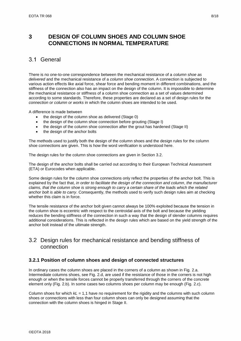
There is no one-to-one correspondence between the mechanical resistance of a column shoe as delivered and the mechanical resistance of a column shoe connection. A connection is subjected to various action effects like axial force, shear force and bending moment in different combinations, and the stiffness of the connection also has an impact on the design of the column. It is impossible to determine the mechanical resistance or stiffness of a column shoe connection as a set of values determined according to some standards. Therefore, these properties are declared as a set of design rules for the connection or column or works in which the column shoes are intended to be used. A difference is made between
• the design of the column shoe as delivered (Stage 0)
• the design of the column shoe connection before grouting (Stage I)
• the design of the column shoe connection after the grout has hardened (Stage II)
• the design of the anchor bolts The methods used to justify both the design of the column shoes and the design rules for the column shoe connections are given. This is how the word verification is understood here. The design rules for the column shoe connections are given in Section 3.2. The design of the anchor bolts shall be carried out according to their European Technical Assessment (ETA) or Eurocodes when applicable. Some design rules for the column shoe connections only reflect the properties of the anchor bolt. This is explained by the fact that, in order to facilitate the design of the connection and column, the manufacturer claims, that the column shoe is strong enough to carry a certain share of the loads which the related anchor bolt is able to carry. Consequently, the methods used to verify such design rules aim at checking whether this claim is in force. The tensile resistance of the anchor bolt given cannot always be 100% exploited because the tension in the column shoe is eccentric with respect to the centroidal axis of the bolt and because the yielding reduces the bending stiffness of the connection in such a way that the design of slender columns requires additional considerations. This is reflected in the design rules which are based on the yield strength of the anchor bolt instead of the ultimate strength.
Design rules for mechanical resistance and bending stiffness of connection
3.2.1 Position of column shoes and design of connected structures
In ordinary cases the column shoes are placed in the corners of a column as shown in Fig. 2.a. Intermediate columns shoes, see Fig. 2.d, are used if the resistance of those in the corners is not high enough or when the tensile forces cannot be properly transferred through the corners of the concrete element only (Fig. 2.b). In some cases two columns shoes per column may be enough (Fig. 2.c). Column shoes for which kL = 1,1 have no requirement for the rigidity and the columns with such column shoes or connections with less than four column shoes can only be designed assuming that the connection with the column shoes is hinged in Stage II.
EOTA TR 068 9/18
©EOTA 2018
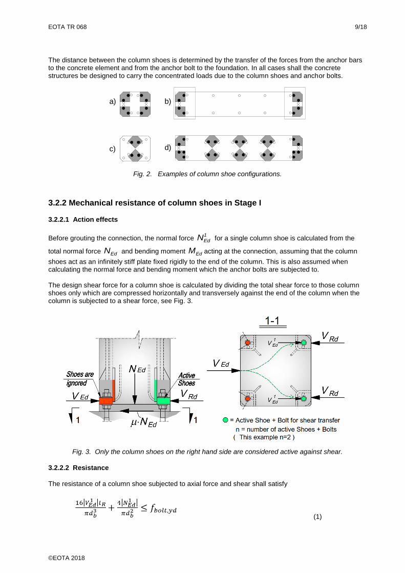
The distance between the column shoes is determined by the transfer of the forces from the anchor bars to the concrete element and from the anchor bolt to the foundation. In all cases shall the concrete structures be designed to carry the concentrated loads due to the column shoes and anchor bolts.
b)
d)
a)
c)
Fig. 2. Examples of column shoe configurations.
3.2.2 Mechanical resistance of column shoes in Stage I
3.2.2.1 Action effects
Before grouting the connection, the normal force 1
EdN for a single column shoe is calculated from the
total normal force EdN and bending moment EdM acting at the connection, assuming that the column
shoes act as an infinitely stiff plate fixed rigidly to the end of the column. This is also assumed when calculating the normal force and bending moment which the anchor bolts are subjected to. The design shear force for a column shoe is calculated by dividing the total shear force to those column shoes only which are compressed horizontally and transversely against the end of the column when the column is subjected to a shear force, see Fig. 3.
Fig. 3. Only the column shoes on the right hand side are considered active against shear.
3.2.2.2 Resistance
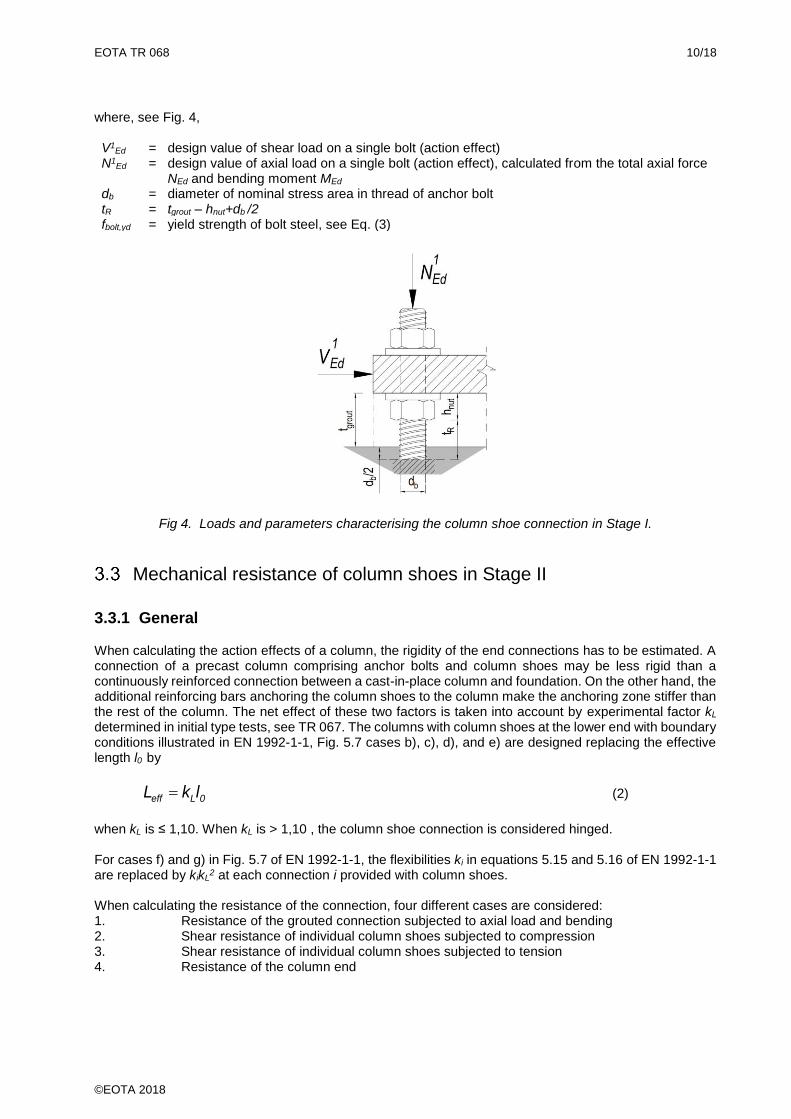
The resistance of a column shoe subjected to axial force and shear shall satisfy
(1)
EOTA TR 068 10/18
©EOTA 2018
where, see Fig. 4, V1
Ed = design value of shear load on a single bolt (action effect) N1
Ed = design value of axial load on a single bolt (action effect), calculated from the total axial force NEd and bending moment MEd
db = diameter of nominal stress area in thread of anchor bolt tR = tgrout – hnut+db /2 fbolt,yd = yield strength of bolt steel, see Eq. (3)
Fig 4. Loads and parameters characterising the column shoe connection in Stage I.
Mechanical resistance of column shoes in Stage II
3.3.1 General
When calculating the action effects of a column, the rigidity of the end connections has to be estimated. A connection of a precast column comprising anchor bolts and column shoes may be less rigid than a continuously reinforced connection between a cast-in-place column and foundation. On the other hand, the additional reinforcing bars anchoring the column shoes to the column make the anchoring zone stiffer than the rest of the column. The net effect of these two factors is taken into account by experimental factor kL determined in initial type tests, see TR 067. The columns with column shoes at the lower end with boundary conditions illustrated in EN 1992-1-1, Fig. 5.7 cases b), c), d), and e) are designed replacing the effective length l0 by
0Leff lkL = (2)
when kL is ≤ 1,10. When kL is > 1,10 , the column shoe connection is considered hinged. For cases f) and g) in Fig. 5.7 of EN 1992-1-1, the flexibilities ki in equations 5.15 and 5.16 of EN 1992-1-1 are replaced by kikL
2 at each connection i provided with column shoes.
When calculating the resistance of the connection, four different cases are considered: 1. Resistance of the grouted connection subjected to axial load and bending 2. Shear resistance of individual column shoes subjected to compression 3. Shear resistance of individual column shoes subjected to tension 4. Resistance of the column end
EOTA TR 068 11/18
©EOTA 2018
3.3.2 Design criterion for grouted section subjected to axial force and bending
The resistance of the grouted section above the foundation and below the column shoes is calculated according to EN 1992-1-1 assuming that the section behaves as a concrete section reinforced with the anchor bolts. For the bolts, the bilinear stress-strain assumption with a horizontal top branch (EN 1992-1-1, 3.2.7 b) is applied assuming that the design strength of the anchor bolt is
fbolt,yd = min{dfbolt,y /M2 ; fbolt,u /bolt} (3) where
d = stiffness factor ≤ 1,00: the value is determined in initial type tests
fbolt,y = yield strength of steel in the anchor bolt fbolt,u = the ultimate strength of steel in the anchor bolt
M2 = material safety factor according to EN 1993-1-8, Table 2.1
bolt = material safety factor of anchor bolt according to the relevant European Technical Assessment (ETA ) or Eurocodes when applicable
Note: According to EN 898-1, the resistance of the anchor bolts is controlled by fbolt,u. However, the tensile and bending resistance of a column shoe connection has to be controlled by fbolt,y because, after yielding, the bending stiffness of the connection becomes indefinite, which makes reasonable structural design impossible. fbolt,y is always
< fbolt,u but due to d and the nationally determined parameters M2 and bolt , dfbolt,y /M2 > fbolt,u /bolt may also be true.
For this reason, Eq. (3) includes two strength values.
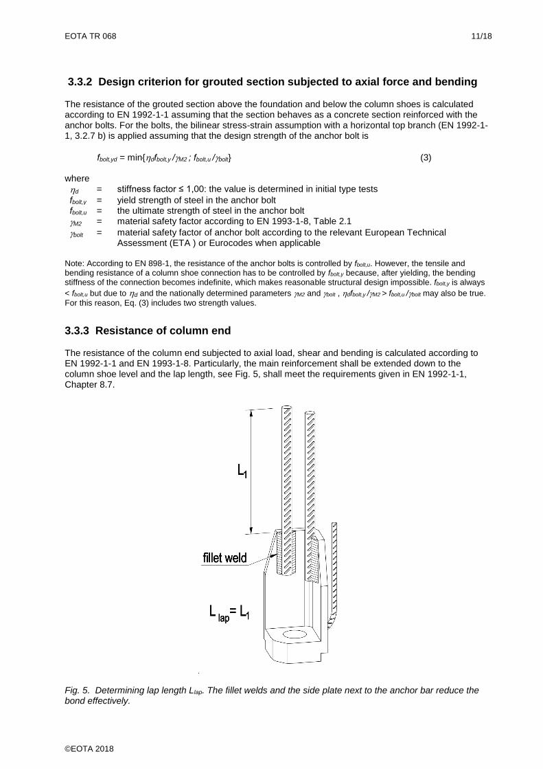
3.3.3 Resistance of column end
The resistance of the column end subjected to axial load, shear and bending is calculated according to EN 1992-1-1 and EN 1993-1-8. Particularly, the main reinforcement shall be extended down to the column shoe level and the lap length, see Fig. 5, shall meet the requirements given in EN 1992-1-1, Chapter 8.7.
Fig. 5. Determining lap length Llap. The fillet welds and the side plate next to the anchor bar reduce the bond effectively.
EOTA TR 068 12/18
©EOTA 2018
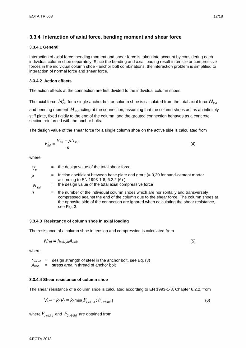
3.3.4 Interaction of axial force, bending moment and shear force
3.3.4.1 General
Interaction of axial force, bending moment and shear force is taken into account by considering each individual column shoe separately. Since the bending and axial loading result in tensile or compressive forces in the individual column shoe - anchor bolt combinations, the interaction problem is simplified to interaction of normal force and shear force.
3.3.4.2 Action effects
The action effects at the connection are first divided to the individual column shoes.
The axial force 1
EdN for a single anchor bolt or column shoe is calculated from the total axial force EdN
and bending moment EdM acting at the connection, assuming that the column shoes act as an infinitely
stiff plate, fixed rigidly to the end of the column, and the grouted connection behaves as a concrete section reinforced with the anchor bolts. The design value of the shear force for a single column shoe on the active side is calculated from
n
NVV EdEd1
Ed
−= (4)
where
EdV = the design value of the total shear force
= friction coefficient between base plate and grout (= 0,20 for sand-cement mortar according to EN 1993-1-8, 6.2.2 (6) )
EdN = the design value of the total axial compressive force
n = the number of the individual column shoes which are horizontally and transversely compressed against the end of the column due to the shear force. The column shoes at the opposite side of the connection are ignored when calculating the shear resistance, see Fig. 3.
3.3.4.3 Resistance of column shoe in axial loading
The resistance of a column shoe in tension and compression is calculated from
NRd = fbolt,ydAbolt (5)
where fbolt,yd = design strength of steel in the anchor bolt, see Eq. (3) Abolt = stress area in thread of anchor bolt
3.3.4.4 Shear resistance of column shoe
The shear resistance of a column shoe is calculated according to EN 1993-1-8, Chapter 6.2.2, from
VRd = ksVt = ksmin{ Rd,vb,1F ; Rd,vb,2F } (6)
where Rd,vb,1F and Rd,vb,2F are obtained from
EOTA TR 068 13/18
©EOTA 2018
2M
basebu,baseb1
Rd,vb,1
tdfak8,0F
= (7)
2M
boltu,boltb
Rd,vb,2
AfF
= (8)
y,bolt
1
b f)MPa0003,0(44,0 −−= (9)
In these expressions ks = a parameter determined in accordance with TR 067, Chapter 6 k1 and ab = coefficients calculated as in EN 1993-1-8, Table 3.4 fbase,u = the ultimate strength of the base plate db = diameter of nominal stress area in thread of anchor bolt tbase = thickness of the base plate
M2 = material safety factor according to EN 1993-1-8, Table 2.1
fbolt,u = ultimate strength of steel of the anchor bolt Abolt = tensile stress area of the anchor bolt
3.3.4.5 Design criterion for column shoe subjected to shear and axial load
The shear resistance of a column shoe subjected to shear and compression shall meet the requirement
Rd
1
Ed VV (10)
where 1
EdV and RdV are calculated from Equations (4) and (6), respectively.
The simultaneous tensile force 1
EdN and shear force 1
EdV in each column shoe shall satisfy the
conditions
1V
V
N4,1
N
Rd
1
Ed
Rd
1
Ed+ (11)
1N
N
Rd
1
Ed (12)
where RdN and RdV are calculated from Equations (5) and (6), respectively.
EOTA TR 068 14/18
©EOTA 2018
Resistance of column shoe components and welds
As a part of the initial type testing, the axial yield resistance of the
• reinforcing bars (anchor bars)
• side plates
• welds connecting the reinforcing bars to the base plate and side plates and
• welds connecting the side plates to the base plate are calculated according to EN 1992-1-1, EN 1993-1-1 and EN 1993-1-8, whichever is relevant. When doing so, it is assumed that the different components of the column shoe as well as their connections are subjected to axial load and the material safety coefficients are set equal to 1,0. The sum of the calculated axial resistances of all anchor bars 1,…,m, the rear bar excluded, shall be
bolt
m
1i
y,boltnom,bolti,anci,y,ancanc AfNAfN =
== (13)
where fanc,y,i = the nominal yield strength of anchor bar i Aanc,i = nominal cross-sectional area of anchor bar i Nbolt,nom = nominal axial resistance of anchor bolt fbolt,y = nominal yield strength of anchor bolt Abolt = stress area in thread of anchor bolt
The sum of the calculated axial resistances of the side plates 1,…,q,
Nplate=∑ fplate,y,iAplate,iqi=1 (14)
shall be able to carry the yield force from the anchor bolt which is eccentric with respect to centroid of section of side plate(s). Here fplate,y,i = the nominal strength of the steel in side plate i Aplate,i = nominal cross-sectional area of the active part of anchor side plate i
Nside,weld, the sum of the calculated nominal resistances of the welds 1,…, p between the side plates and
the base plate, calculated in the direction of the anchor bolt, shall be able to carry the eccentric nominal yield force from the anchor bolt. Nside,weld is calculated according to EN 1993-1-8, Chapter 4.5 assuming axial tension in the side plates.
N𝑠𝑖𝑑𝑒,𝑤𝑒𝑙𝑑 = ∑ Fw,i𝑝i=1 (155)
where Fw,i = the nominal resistance of the weld joint i
The sum of the calculated nominal resistances of the welds between the side plates and the anchor bars i, the rear bar excluded, shall be able to carry the eccentric yield force from the anchor bolt. The summation is extended over all straight bars welded to the side plate(s).
EOTA TR 068 15/18
©EOTA 2018
4 FIRE RESISTANCE OF COLUMN SHOES WITHOUT COVER
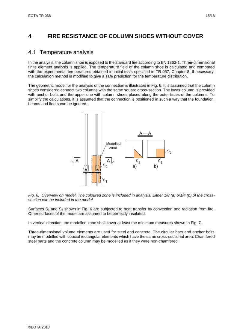
Temperature analysis
In the analysis, the column shoe is exposed to the standard fire according to EN 1363-1. Three-dimensional finite element analysis is applied. The temperature field of the column shoe is calculated and compared with the experimental temperatures obtained in initial tests specified in TR 067, Chapter 8. If necessary, the calculation method is modified to give a safe prediction for the temperature distribution. The geometric model for the analysis of the connection is illustrated in Fig. 6. It is assumed that the column shoes considered connect two columns with the same square cross-section. The lower column is provided with anchor bolts and the upper one with column shoes placed along the outer faces of the columns. To simplify the calculations, it is assumed that the connection is positioned in such a way that the foundation, beams and floors can be ignored.
A A
A A
S1
S2
S1S2
S1
a) b)
Modelled zone
Fig. 6. Overview on model. The coloured zone is included in analysis. Either 1/8 (a) or1/4 (b) of the cross-section can be included in the model. Surfaces S1 and S2 shown in Fig. 6 are subjected to heat transfer by convection and radiation from fire. Other surfaces of the model are assumed to be perfectly insulated. In vertical direction, the modelled zone shall cover at least the minimum measures shown in Fig. 7. Three-dimensional volume elements are used for steel and concrete. The circular bars and anchor bolts may be modelled with coaxial rectangular elements which have the same cross-sectional area. Chamfered steel parts and the concrete column may be modelled as if they were non-chamfered.
EOTA TR 068 16/18
©EOTA 2018
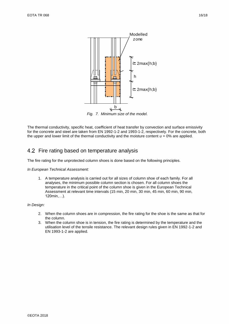
h
Modelled zone
2max{h;b}
2max{h;b}
b
Fig. 7. Minimum size of the model. The thermal conductivity, specific heat, coefficient of heat transfer by convection and surface emissivity for the concrete and steel are taken from EN 1992-1-2 and 1993-1-2, respectively. For the concrete, both the upper and lower limit of the thermal conductivity and the moisture content u = 0% are applied.
Fire rating based on temperature analysis
The fire rating for the unprotected column shoes is done based on the following principles. In European Technical Assessment:
1. A temperature analysis is carried out for all sizes of column shoe of each family. For all analyses, the minimum possible column section is chosen. For all column shoes the temperature in the critical point of the column shoe is given in the European Technical Assessment at relevant time intervals (15 min, 20 min, 30 min, 45 min, 60 min, 90 min, 120min,…).
In Design:
2. When the column shoes are in compression, the fire rating for the shoe is the same as that for the column.
3. When the column shoe is in tension, the fire rating is determined by the temperature and the utilisation level of the tensile resistance. The relevant design rules given in EN 1992-1-2 and EN 1993-1-2 are applied.
EOTA TR 068 17/18
©EOTA 2018
5 ANALYSIS REPORT
The report shall include the calculations to verify that the requirements presented in Section 3.4 for the column shoe components and welds are fulfilled. In addition, the justification of the temperature analysis method, based on fire tests performed and reported according to TR 067, as well as the fire rating process shall be documented in the report.
EOTA TR 068 18/18
©EOTA 2018
6 REFERENCE DOCUMENTS
As far as no edition date is given in the list of thereafter, the publication in its current version is of relevance. EAD 200102-00-0302 Evaluation Assessment Document of Column Shoes
EN 1363-1 Fire resistance tests. Part 1: General Requirements
EN 1990 Eurocode - Basis of structural design
EN 1992-1-1 Eurocode 2: Design of concrete structures - Part 1-1: General rules and rules for buildings
EN 1992-1-2 Eurocode 2: Design of concrete structures - Part 1-2: General rules - Structural fire design
EN 1993-1-1 Eurocode 3: Design of steel structures - Part 1-1: General rules and rules for buildings
EN 1993-1-2 Eurocode 3: Design of steel structures - Part 1-2: General rules - Structural fire design
EN 1993-1-8 Eurocode 3: Design of steel structures - Part 1-8: Design of joints
TR 067 Bending of column shoe connections