Embed Size (px)
DESCRIPTION
Calculation of Wave and Current Loads on Launching Offshore Jacket
Citation preview

Journal of Marine Science and Application, Vol.5, No.4, December 2006, pp.01-07
Calculation of wave and current loads on launching
offshore jacket
ZHANG Guang-fa, JI Zhuo-shang, LI Tie-li, and LIN Yan
Department of Naval Architecture and Ocean Engineering, Dalian University of Technology, Dalian 116024, China
Abstract: It’s very complicated to calculate and analyze the wave and current loads on naval
architectures since the sea condition is uncertain and complicated and the determinants vary from
different form types and dimensions. For calculating the wave and current loads on upright
small-long-size pipe, the Morrison equation is practical and applied. Jacket platform is a kind of offshore
space frame structure comprised of lots of poles that are circular cylinders with small diameter and in the
oblique status relative to seabed. In this paper, based on Morrison equation, the specific method and
procedure calculating the wave and current loads on launching jacket are given and applied on a typical
launching jacket. The instance shows that the method and procedure are convenient and make the
calculation and analysis in good agreement with actual launching.
Keywords: launching;hydrodynamic force; morrison equation; jacket platform
CLC number: U661.1 Document code: A Article ID: 1671-9433(2006)04-0001-07
1 Introduction1
It’s very complicated to calculate and analyze the wave
and current loads on naval architectures since the sea
condition is uncertain and complicated and the
determinants vary from different form types and
dimensions. The induced wave loads on naval
architecture result from the pressure field formed by
wave and the load can be classified into three kinds: drag
force, inertia force and diffracting force. Drag force is
caused by the current disturbance aroused by the sea.
Inertial force is composed of two components, one of
which is the force induced by the pressure field of
incident wave and named as Froude-Crylov force,
another is the additional mass force caused by the inertia
of water. Diffracting force comes into being when taking
into account the wave diffraction due to the structure
body. For the mentioned above wave inductive loads
components, which should be laid particular stress on, it
depends on the model type and dimension of the
structure and the wave environment [1]
.
Jacket platform is a kind of offshore space frame
Received date :2006-06-22.
Foundation item: Supported by Item of Doctor Subject of
Colleges and University (No.2000014125) and the Education
Office of Liaoning Province (No.05l091).
structure comprised of lots of poles that are circular
cylinders with small diameter. The character of the
poles member of jacket is that when the progressive
direction of current is vertical to its axis, due to the
viscosity of the sea water, the current will be separated
on the back of the circular cylinder, which results in a
complicated flowing. For this kind of diffracting flow,
it is difficult to analyze and obtain a practical result
with the theory of potential flow of idea fluid. On the
other side, for the body with small size relative to the
wavelength, generally speaking, D/L<0.2, where D is
diameter of the body and L is wavelength, the drag
force and inertia force are major components.
Currently, the experience analysis and experiment
measure are adopted to resolve the practical
engineering questions, in which the dominant is
Morrison equation, which adopts the semi-experience
and semi-theory method. The Morison equation is
released by American scientists Morrison, O’Brien
and Johnson for calculating the wave and current
loads on small diameter circular cylinders in the sea
water.
For the current load on structure, basically the
wave-current combination may be treated either as a
complex fluid-mechanical phenomenon where the
interaction of wave and current is take into account or

Journal of Marine Science and Application, Vol.5, No.4, December 2006 2
as a relatively simple phenomenon where the
interaction is ignored and the current is simply
superimposed on waves. If the current is in the
direction of wave propagation, the wave amplitude
will decrease and its length increase. If the current is
opposed to the wave, the wave will become steeper
and shorter. In practical engineering, the second
method is adopted. In calculation of wave load, the
current velocity and acceleration are superimposed on
wave water particle to consider the action of current
on structure.
In the jacket launching system, both of the poles
structure of the jacket and its motion are complicated .
When calculating the interaction of the barge and the
jacket and the dynamic response parameters, wave
and current loads are functions of dynamic response
parameters, which are the unknown qualities to be
resolved yet, so it’s difficult and even impossible to
calculate wave and current loads directly.Based on the
Morrison equation, a new and reasonable approach is
described here in somewhat greater details than
needed for calculating wave and current loads on
jacket and launching analysis of the system. The idea
is to calculate dynamically and iteratively the wave
and current loads on oblique pipes like poles of jacket
and a complicated system like the launching jacket.
2 Morrison equations and the calculation
of wave load on the cylindrical pile
with small size
The basic principle of Morrison equation is that, the
wave field will propagate without the effect of the
body basically, namely the velocity and acceleration
will be calculated by its original level dimension and
with the original wave theory, so the wave load on the
cylindrical pile can be comprised of two components
as follows:
1) Drag forced
F , which is the velocity force caused
by the undisturbed wave velocity field. The drag force
on the pile is directly proportional to the square of the
wave velocity vertical to the pile:
2d 0.5 d
d dF C Du lρ= , (1)
where d
C is drag coefficient that is relevant to
Reynolds number Re and is a function of current
status, D diameter of the cylinder, ρ the density
of seawater, dl the length of the pile, u the
velocity of wave water particle. As having known that
velocity and acceleration of particle induced by wave
are periodic functions and their horizontal components
may be positive or negative direction along x-axis, i.e.
in the progressive direction of waves or inverse.
Therefore the square of horizontal component u
should be substituted by | |u u in Eq.(1):
d 0.5 | | dd d
F C D u u lρ= .
2) Inertia force m
F , which is the acceleration force
on the pile. The inertia force is directly proportional to
the wave acceleration vertical to the pile:
2d 0.25 π d
m mF C D a lρ= ,
where m
C is the inertia coefficient, a the wave
acceleration vertical to the pile. So the summary wave
force on the pile is:
2d d d 0.5 d 0.25 π d .
d m d mF F F C D u u l C D a lρ ρ= + = +
3 Calculating model of wave force on
the pole member of jacket
3.1 Basic calculating models
Jacket is structured by lots of welding poles locating
in all kinds of directions, including vertical, horizontal
and oblique directions. During launching, the
direction of center axis of an individual pole is not
vertical and fixed to the direction of current velocity
and acceleration.
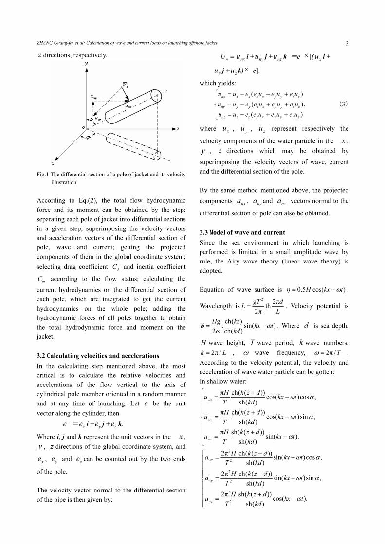
As Fig.1 shows, the flow hydrodynamics and velocity
of a differential section of a jacket pole can be
projected to the fixed global coordinate system
according to the location of the jacket pole. Since
Morrison equations may be applied to a cylindrical
member oriented in a random manner with respect to
the mud line, the Eq.(1) can be re-written as:
d
d
d
x
y
z
F
F
F
⎡ ⎤⎢ ⎥⎢ ⎥⎢ ⎥⎣ ⎦
= 0.5 dd
C D U lρ
nx
ny
nz
u
u
u
⎡ ⎤⎢ ⎥⎢ ⎥⎢ ⎥⎣ ⎦
+
20.25 π d
mC D lρ .
nx
ny
nz
a
a
a
⎡ ⎤⎢ ⎥⎢ ⎥⎢ ⎥⎣ ⎦
(2)
where nx
u , ny
u , nz
u and nx
a , ny
a , nz
a represent
the components of velocity and acceleration vectors of
flow water particle vertical to the differential section
of the pole in the global coordinate in the x , y ,
ZHANG Guang-fa, et al: Calculation of wave and current loads on launching offshore jacket 3
z directions, respectively.
Fig.1 The differential section of a pole of jacket and its velocity
illustration
According to Eq.(2), the total flow hydrodynamic
force and its moment can be obtained by the step:
separating each pole of jacket into differential sections
in a given step; superimposing the velocity vectors
and acceleration vectors of the differential section of
pole, wave and current; getting the projected
components of them in the global coordinate system;
selecting drag coefficient d
C and inertia coefficient
mC according to the flow status; calculating the
current hydrodynamics on the differential section of
each pole, which are integrated to get the current
hydrodynamics on the whole pole; adding the
hydrodynamic forces of all poles together to obtain
the total hydrodynamic force and moment on the
jacket.
3.2 Calculating velocities and accelerations
In the calculating step mentioned above, the most
critical is to calculate the relative velocities and
accelerations of the flow vertical to the axis of
cylindrical pole member oriented in a random manner
and at any time of launching. Let e be the unit
vector along the cylinder, then
e =xe i +
ye j +
ze k.
Where i, j and k represent the unit vectors in the x ,
y , z directions of the global coordinate system, and
xe ,
ye and
ze can be counted out by the two ends
of the pole.
The velocity vector normal to the differential section
of the pipe is then given by:
nU =
nxu i +
nyu j +
nzu k =e × [(
xu i +
yu j +
zu k)× e].
which yields:
( )
( ).
( )
nx x x x x y y z z
ny y y x x y y z z
nz z z x x y y z z
u u e e u e u e u
u u e e u e u e u
u u e e u e u e u
⎧ = − + +⎪
= − + +⎨⎪ = − + +⎩
(3)
where x
u , y
u , z
u represent respectively the
velocity components of the water particle in the x ,
y , z directions which may be obtained by
superimposing the velocity vectors of wave, current
and the differential section of the pole.
By the same method mentioned above, the projected
components nx
a , ny
a and nz
a vectors normal to the
differential section of pole can also be obtained.
3.3 Model of wave and current
Since the sea environment in which launching is
performed is limited in a small amplitude wave by
rule, the Airy wave theory (linear wave theory) is
adopted.
Equation of wave surface is 0.5 cos( )H kx tη ω= − .
Wavelength is2
2πth
2π
gT dL
L= . Velocity potential is
ch( ). sin( )
2 ch( )
Hg kzkx t
kdφ ω
ω= − . Where d is sea depth,
H wave height, T wave period, k wave numbers,
2π /k L= , ω wave frequency, 2π /Tω = .
According to the velocity potential, the velocity and
acceleration of wave water particle can be gotten:
In shallow water:
π ch( ( ))cos( )cos ,
sh( )
π ch( ( ))cos( )sin ,
sh( )
π sh( ( ))sin( ).
sh( )
wx
wy
wz
H k z du kx t
T kd
H k z du kx t
T kd
H k z du kx t
T kd
ω α
ω α
ω
⎧ += −⎪
⎪⎪ +
= −⎨⎪⎪ +
= −⎪⎩
2
2
2
2
2
2
2π ch( ( ))sin( )cos ,
sh( )
2π ch( ( ))sin( )sin ,
sh( )
2π sh( ( ))cos( ).
sh( )
wx
wy
wz
H k z da kx t
T kd
H k z da kx t
T kd
H k z da kx t
T kd
ω α
ω α
ω
⎧ += −⎪
⎪⎪ +⎪
= −⎨⎪⎪ +⎪ = −⎪⎩

Journal of Marine Science and Application, Vol.5, No.4, December 2006 4
In deeper water:
πcos( )cos ,
πcos( )sin ,
πsin( ).
kz
wx
kz
wy
kz
wz
Hu e kx t
T
Hu e kx t
T
Hu e kx t
T
ω α
ω α
ω
⎧= −⎪
⎪⎪
= −⎨⎪⎪
= −⎪⎩
2
2
2
2
2
2
2πsin( )cos ,
2πsin( )sin ,
2πcos( ).
kz
wx
kz
wy
kz
wz
Ha e kx t
T
Ha e kx t
T
Ha e kx t
T
ω α
ω α
ω
⎧= −⎪
⎪⎪
= −⎨⎪⎪
= −⎪⎩
where α is the direction of wave propagating.
The surface current in the sea includes mainly two
components: tidal current and local wend current. The
factor of current such as velocity should be selected
according to the statistic data obtained by practical
experience. Generally, the current velocity varies with
the sea depth, and is calculated here according to the
calculating formulae recommended by reference [6].
0
0
, ( ( 10) 0)( )
lg(1 9 /(10 )), ( ( 10))
t
t
t
U h zU z
U z h h z h
− − ≤ ≤⎧= ⎨
+ − − < < − −⎩
0 0 0 0
0
( ) / , ( 0)( )
0,( )
f
f
U h z h h zU z
z h
+ − ≤ ≤⎧= ⎨
< −⎩
( ) ( ) ( ),s t f
U z U z U z= +
( )cossx s
u U z β= ,
( )sinsy s
u U z β= ,
0sz
u = .
where h is water depth in m, 0h can be chosen as
50 m, 0t
U , 0fU the tidal velocity and local wend
current velocity of surface respectively, ( )c
U z the
total velocity of current in the place with z depth, β
the direction of current.
Superimposing the velocities and accelerations
calculated by formulae in chart3.3, namely that of
wave and current, and ignoring the acceleration of
current, the total velocity and acceleration of wave
and current can be obtained:
,
,
.
cx wx sx
cy wy sy
cz wz sz
u u u
u u u
u u u
= +⎧⎪
= +⎨⎪ = +⎩
,
,
.
cx wx
cy wy
cz wz
a a
a a
a a
=⎧⎪
=⎨⎪ =⎩
3.4 Selections of drag coefficient d
C and inertia
coefficientm
C
The hydrodynamic coefficients d
C and m
C can be
selected on the basis of the data of experience and
experiment. They are functions of Reynolds number
Re, relative roughness of surface for cylinder K/D,
and scale of cylinder and wave parameters that
depends on the wave theory selected to study.
According to reference [4], the hydrodynamic
coefficient d
C and m
C of the cylinder can be
obtained by some criterions recommended by each
state based on some wave theory.
An overall advice on how to select d
C and m
C was
given by Sarpkay and Isaccson(1981): for a smooth
cylinder, the Reynolds number and so-called
Keulegan-Carpenter number K can be calculated with
the Stokes fifth order wave theory or stream function
theory. Accordingly with the Re and K, d
C and m
C
can be found out in the figures provided by reference [5].
If 6Re 1.5 10> × , namely beyond the maximums of
the figures, d
C =0.62 and m
C =1.8[4].
The second method is here adopted to get the
hydrodynamic coefficients d
C and m
C of upright
cylinder pole. Referring to the assumption posed by
Hoener(1965), who thought when Reynolds number
was in supercritical zone, the vertical pressure would
be free from tangential velocity, the Re and K could
be calculated by the following formulae:
| | /n
Re U D ν= , | | /n
K U T D= ,
where ν is water viscosity factor ; T oscillation
period.
With the parameters Re and K calculated above, d
C
and m
C can be found out in the Fig.3.19 and Fig 3.20
in reference [5] respectively. And then the
hydrodynamic coefficients '
dC and '
mC of the
oblique cylinder pole can be calculated with the
Eq.3.10 provided by reference [4]:
' 3 1(1 cos ) ,d d
C C µ−
= −
'
/ sin ,m m
C C µ=
tan tan / cos( ),μ θ α β= +
where β is the included angle of current direction
ZHANG Guang-fa, et al: Calculation of wave and current loads on launching offshore jacket 5
and Y-axis, α the included angle of current direction
and wave propagating direction, θ the obliquity of
the oblique cylinder pole.
4 Model of calculation of hydrodynamic
force on jacket
According to the above analysis, it can be known that
the hydrodynamic force on jacket during launching is
a function of the motion parameters such as displace,
velocity, acceleration, angle, angular velocity, angular
acceleration, which are unknown and resolving
dynamic response parameters, the appropriate method
may be a dynamic and iterating method which is
described as: at the initial status of launching jacket,
the moving parameters of the next time step can be
obtained with difference equation. Secondly,
calculating hydrodynamic jacket with the model
mentioned above, and substituting it into the motion
equation to solve the equation iteratively until the
results errors is less than some given precision degree
to count out the unknown qualities, namely motion
parameters; and then doing the next step calculation.
The specific procedure is described as follows:
1) With the motion parameters counted out in the last
time step, calculate the initial iterating motion
parameters of the current time step with difference
equation.
2) Calculate the velocity and acceleration of the
differentiate section of jacket pole. Differentiating
separate each pole of jacket into n sections, and the
coordinate of the differential section center in the
jacket coordinate system can be counted out and
transferred into global system by the coordinate
transferring Eq.(4)
i
i
i
x
y
z
⎡ ⎤⎢ ⎥⎢ ⎥⎢ ⎥⎣ ⎦
=Sjg
ij
ij
ij
x
y
z
⎡ ⎤⎢ ⎥⎢ ⎥⎢ ⎥⎣ ⎦
+
0
0
0
,
x
y
z
⎡ ⎤⎢ ⎥⎢ ⎥⎢ ⎥⎣ ⎦
(4)
where Sjg is the matrix transferring coordinate from
jacket system to global system, ( , , )ij ij ijx y z and
( , , )i i ix y z are coordinate vectors of section center in
jacket system and global system respectively,
0 0 0( , , )x y z is the coordinate of gravity center of
jacket in global system. Differentiating the Eq.(4) one
time and twice with respect to time, respectively the
velocity and acceleration of the pole differentiating
section can be obtained as Eq.(5) and Eq.(6).
0 0 0 0 0 0
0 0 0 0 0 0
0 0 0 0 0 0
( , , , , , ),
( , , , , , ),
( , , , , , ).
ix x x y z x y z
iy y x y z x y z
iz z x y z x y z
v f v v v w w w
v f v v v w w w
v f v v v w w w
⎧ =⎪
=⎨⎪ =⎩
(5)
0 0 0 0 0 0 0 0 0 0 0 0
0 0 0 0 0 0 0 0 0 0 0 0
0 0 0 0 0 0 0 0 0 0 0 0
( , , , , , , , , , , , ),
( , , , , , , , , , , , ),
( , , , , , , , , , , , ),
ix x x y z x y z x y z x y z
iy y x y z x y z x y z x y z
iz z x y z x y z x y z x y z
a f v v v a a a w w w
a f v v v a a a w w w
a f v v v a a a w w w
ω ω ω
ω ω ω
ω ω ω
⎧ =⎪
=⎨⎪ =⎩
(6)
where
0 0 0 0 0 0 0 0 0 0 0 0 0 0 0, , , , , , , , , , , , , ,
x y z x y z x y z x y z x y zv v v a a a w w w w wω ω ω ω
represent the velocity and acceleration components in
the x , y , z directions respectively.
3) Calculate the components of unit vector of the pole
axis xe ,
ye and
ze . Let ( , , )
a a ax y z and ( , , )
b b bx y z
be the coordinate of the two end points of the pole in
the global system.
2 2 2| | ( ) ( ) ( ) ,a b a b a b
e x x y y z z= − + − + −
( ) / | |,x a be x x e= −
( ) / | |,y a be y y e= −
( ) / | | .z a be z z e= −
4) Calculate the components of velocity and
acceleration of flow in x , y , z directions of global
system by chart 3.3.
5) Calculate the velocity and acceleration of current in
the direction vertical to pole center axis. Firstly
calculate the components of velocity and acceleration
of flow relative to the pole in x , y , z directions of
global system with Eq.(7). And then calculate the
velocity and acceleration of flow in the direction
vertical to pole axis by Eq.(3).
,
,
.
x cx ix
y cy iy
z cz iz
u u v
u u v
u u v
= −⎧⎪
= −⎨⎪ = −⎩
,
,
.
x cx ix
y cy iy
z cz iz
a a a
a a a
a a a
= −⎧⎪
= −⎨⎪ = −⎩
(7)
6) Calculate the drag coefficient d
C and inertia
coefficient m
C according to chart 3.4.
7) Calculate the hydrodynamic force on the
differentiated section of pole by Eq.(2).
8) Superimpose the hydrodynamics of all
differentiated sections of all poles of jacket and the
wave, and the current force on the jacket can be
obtained.
9) Substitute the hydrodynamics above obtained into
the system equation, and resolve the equation with
iterating method to get the motion parameters.
10) Do the next calculation.

Journal of Marine Science and Application, Vol.5, No.4, December 2006 6
5 Example
According to the mentioned above principle and
mathematic model, the calculating program is madden.
With the program, a kind of classic jacket and barge
launching system with the sea condition where the
wind, wave and current have 45 degree incidence
angle is calculated. The Table 1 lists the base input
data. The Fig.2 shows the time history illustration of
the calculating result of wave and current loads on the
jacket. The Fig.3 and Fig.4 show the time history
illustration of velocity and acceleration of jacket
gravity center respectively. The launching trajectory is
shown in the Fig.5.
Table 1 The base data of the launch system
Base data Barge Jacket
Weight /t 10 790.91 5 500
x /m -7.484 -11.7
y/m 0 0
z/m 4.405 29.5
Ix/m4 2.556E+09 3.291E+09
Iy/m4 4.266E+09 8.682E+09
Iz/m4 4.516E+09 8.237E+09
Ixy/m4 -213 378 259.1
Ixz/m4 -7 943 337 -7.05E+08
Iyz/m4 3 576.3 118.6
Friction coefficient 0.08
Initial slide Velocity/ m∙s-1 0 0.014
Ship length/m 119.15
Ship wide /m 30.5
Ship height /m 8
Cube form coefficient 0.955
Initial draft /m 4.535
Table 2 The environment data of the launch system
Environment data
Sea depth /m 110
Wind velocity / m∙s-1 9
Tidal current velocity / m∙s-1 0.2
Wend current velocity/ m∙s-1 0.5
Wave height /m 2
Wave period /s 10
Pole number 722
The jacket has 722 poles whose coordinate and form
parameters data are input with a file. The coordinates
of the 8 outline points are as follows:(-74.744 15,
-9.260 37, -14.714 3), (-77.042 38, -9.260 37, 3.663 29),
(44.400 73, -24.804 93, 34.516 13), (50.556 8,
-24.80493,-14.710 3), (-74.744 15, 9.260 37, -14.714 3),
(-77.0423 8, 9.260 37, 3.663 29), (44.400 73, 24.804 93,
34.516 13), (50.556 8, 24.804 93, -14.710 3).
The diameters of the poles are from 0.61m to 2.006 6 m,
and the thickness of the poles pipes are from 0.012 7 m
to 0.05 m..
Fig.2 The time history illustration of wave and current loads
on jacket
-8
-6
-4
-2
0
2
4
6
8
0.0 8.0 16.0 24.0 32.0 40.0
Time/s
velocity/m.s-1
jacket.vx
jacket.vy
jacket.vz
Fig.3 The time history illustration of velocity of jacket gravity
center
-3
-2
-1
0
1
2
3
0.0 8.0 16.0 24.0 32.0 40.0
Time/s
acceleration/m.s-2
jacket.ax
jacket.ay
jacket.az
Fig.4 The time history illustration of acceleration of jacket
gravity center
-8.0
-6.0
-4.0
-2.0
0.0
2.0
4.0
6.0
8.0
0.0 8.0 16.0 24.0 32.0 40.0
Time/s
hydrodynamic/1000kN
Fjc.x
Fjc.y
Fjc.z
Hydrodynamic/k
N
×1000

ZHANG Guang-fa, et al: Calculation of wave and current loads on launching offshore jacket 7
Fig.5 The launching trajectory illustration of the launching
system
Where ‘Fjc.x’, ‘Fjc.y’, ‘Fjc.z’ are the components of
wave and current loads on jacket at x, y, z axis of
jacket coordinate system respectively. ‘jacket.vx’,
‘jacket.vy’, ‘jacket.vz’ are the components of velocity
of jacket gravity center. ‘jacket.ax’, ‘jacket.ay’,
‘jacket.az’ are the components of acceleration of
jacket gravity center.
6 Conclusions
The example shows that the calculating result is in
good agreement with the actual launching.
1) The wave and current loads on jacket will be
maximums at the time when it submerges into water.
The reason is that the velocity, acceleration, angle
velocity and angle acceleration of jacket all arrive at
the maximums at this time, and the number of poles
submerging into water is great.
2) Compared with x and y directions, the wave and
current loads on jacket in the y direction is much less,
since the transverse moving velocity and acceleration
of jacket is much less than longitudinal and
perpendicular.
3) The time history trend of the wave and current
loads on jacket is coincident with that of the velocity
of jacket, and the acceleration affects the loads just a
little, for the velocity of jacket is magnitude during the
launching and the acceleration is much less.
Additionally, according to the above-calculated result,
some conclusions can be gotten as follows:
1) Since there are interferences and superposing
between jacket poles, the wave and current loads on
jacket would be calculated on the high side, as a result,
the resolve on the motion equations of the system is
not coincident to the real launching course. During the
practical calculation, an interference coefficient is
multiplied on the results and the result is in good
agreement with the real launching.
2) The wave and current force on jacket mainly loads
in the longitudinal direction (namely the launching
direction), and the transverse direction loads will
increase with the incident angle of the wind, wave and
current increasing to 90 degree, at which the loads
arrive at maximums which is very dangerous, so the
status should be escaped.
References:
[1] LI Runpei, WANG Zhinong. The strength analysis for
offshore structures [M]. Snanghai: Shanghai Jiaotong
University Press, 1992 (in Chinese).
[2] HUANG Xianglu, LU Xinshen. Hydromechanics and
structure dynamical response of ship engineering [M].
Shanghai: Shanghai Jiaotong University Press, 1992 (in
Chinese).
[3] ZHANG Guangfa, JI Zhuoshang, LI Tieli, LIN Yan.
Program design for launching analysis of platform jacket
[J]. Journal of Dalian University of Technology, 2004(3):
416 – 420 (in Chinese).
[4] LI Yucheng, TENG Bing. Wave action on maritime
structures [M]. Beijing: Ocean Press, 2002 (in Chinese).
[5] SARPKAYA TURGUT, ISAACSON M . Mechanics of
wave forces on offshore structures [M]. NY: Van
Nostrand Reinhold Co, 1981.
[6] WANG Yanying. Waves and wave loads on offshore
structures[M]. Dalian: Dalian Maritime University Press,
2003.
ZHANG Guang-fa was born in 1970. He is a
doctor of Dalian University of Technology.
His current research interests include ship
CADand ocean engineering.