Embed Size (px)
Citation preview
vOLTAGE iH VOLT !GH V _TAGE IH VO AGE OLTA H VOL VOLT 3H VO VOLTA 7OLTAG VO LTAG .GE HIGH CAGE HI D LTAG TAGE GE HIG LTAGE -i VOLT !!GH H V GE )L i
IGH VOLTAGE HIGH VOLTAGE HIGH VC
VOLTAGE HIGH VOLTAGE HIGH OLTAGE HIGH VOLTAGU HI(
-'H VOLTAGE HIGH VOLT, -HG- VOLTAGE HIGH
GE HIGH VOLTA" AGE HIGH VOI.
TAGE HIGH E HIGH V(
E HIGI H V( VO
C
L
T/ OLTAG'
H AGE HIGH VOLL AGE HIGH VOLTAGE HIGH
VOLTAGE H'GH VOLTAGE HI( HIGH VOLTAGE HIGH VOLTAGE HIGH
OLTAGE HIGH VOLTAGE HIGH VOLTAGE IGH VOLTAGE HIGH VOLTAGE HIGH VOL
\CF PIG, O'_TAGF HIGH VOLTAGE HIGH \
Ai" HI ..7.1-1 VOLTAGE HIGH VOLTAGE HIGH VOLTAC `OLTAGE riIGH VGL-i-r1GE HIGH VCLTAGE HIGH VO IIGH Vr I VOLT J LTAG .TAGE )LTAGE i VOLTAGE HIGH VOLTAGE HIGH VOLTAGE HIGH `
)LTAGE HIGH VOLTAGE HIGH VOLTAGE HIGH VG'
oi rna www.americanradiohistory.com
Vow! CONAR Offers Two Calculators
Feature -loaded 8 -Digit Pocket
Calculator
Seldom if ever have so
many calculating short- cuts been provided in a
handy type of pocket calculator. The ideal model for those who expect a lot more than just the "four rules" from their pocket calculator.
Accurate, instant answers to a wide variety of trig, inverse trig, and logarithm calculations from a slim, pocketable ELSI MATE calculator with practically limitless capacity and an independently addressable memory . . Plus a factorial key for permutations and combinations, a degree/ minute/second key, square and cube root keys, and DEG/RAD/GRAD switch
. Plus a bright fluorescent display with zero suppres- sion and power from ac
(with adapter) or two dry cells . . . . A pocketable "computer" that provides fingertip calculating for scientists, mathematicians, engineers, and students.
Only 14.95 Plus $1.50 shipping
and handling Stock No. EN118
Only
i
29.95 Plus $1.50 shipping
and handling Stock No. EN501
Check these features:
Advanced 8 -digit model with pocketable dimensions. Separate command keys for wider variety of calculation. Independently addressable memory with memory plus and memory minus keys. Floating (F)/fixed (0-2-4) decimal point plus add mode. Convenient round -off in fixed decimal point or add mode. One touch sign change key. Instant answers to constant, power, tax/discount, percent change, reciprocal, and many other calculations. Three handy power sources: ac with optional adapter/ charger, dry cells, or optional rechargeable Ni -Cd batteries. Bright,easy-to-read fluorescent display with zero suppression. Reliable LSI circuitry.
8 -Digit Mantissa/ 2 -Digit Exponent
Scientific Calculator With Memory
Calculations: Four arithmetic, constant multiplication and division, power, reciprocal, chain multiplication and division, memory, etc.
Scientific functions: sin x, cos x, tan x, sin1 x, cos -1 x, tan 1 x, ex, 10x, In, log, Yx,
3J x2, 1/x, pi, n!, degree/
minute/second H decimal notation degree, etc.
Optional AC Adapter/Charger Fits Either Calculator Stock No. AC017 Only $2.95
www.americanradiohistory.com
a.
i September/October 1977
Volume 35, No.5
ournal
James D. Crudup 2
Harold Kinley 11
21
Ted Beach 23
Tom Nolan 28
R
HIGH -VOLTAGE REGULATION
THE EAR DOCTOR RETURNS
NRI HONORS PROGRAMS AWARDS
HAM NEWS
ALUMNI NEWS
EDITOR AND PUBLISHER William F. Dunn TECHNICAL EDITOR Ted Beach MANAGING EDITOR Kathy Waugh EDITORIAL ASSISTANTS Laura Blalock Noreen Duszynski Laurie Munk Audrey Rothstein Cynthia Thompson Carol Volkman STAFF ARTISTS Ernie Blaine Bill Massey Peter Schmidt Arthur Susser
In this issue, NRI Journal veteran James Crudup draws on his vast technical servicing experience to explain High -voltage control. In addition, the ear doctor, Harold Kinley calls again to discuss more Citizens Band servicing case histories.
The NRI Journal is published bimonthly by the National Radio Institute, a division of the McGraw- Hill Center for Continuing Education, 3939 Wisconsin Avenue, Washington, D.C. 20016. The subscription price is two dollars yearly or 35 cents per single copy. Second-class postage is paid at Washington, D.C.
\,
www.americanradiohistory.com
VOLTAGE HIGH VOLTAGE HIGH VOLTAGE HIGH VO H VOLTAGE HIGH VOLTAGE HIGH VOLTAGE HIGH
VOLTAGE HIGH VOLTAGE HIGH VOLTAGE HIGH VO TAGE HIGH VOLTAGE HIGH VOLTAGE HIGH VOLTA H VOLTAGE HIGH VOLTAGE HIGH VOLTAGE HIGH
VOLTAGL_H. GH VOLTAGF HIGH VOLTAGE HIGH VO' OLTAG le \ 0 _Tf Cf: H (41 J lifh.CE HIGH VOL H VOL ",H VOLTAGE R, ` LTAGE HIGH Vi VOLTA h V L-.- Gr 1 G1. 4 AGE HIGH VOL'' "AGE H I i AGE nlGH JO GE HIGH VOLTAG1 LTAGE OLTAGE HIGH V TAGE HIGH VOLT
'VOLTAGE HIGH VOLTAGE HIGH VOLTAGE HIGH VO 3H VOLTAGE HIGH VOLTAGE HIGH VOLTAGE HIGH HIGH VOLTAGE HIGH VOLTAGE HIGH VOLTAGE HIG.
!XGE HIGH VOLTAGE HIGH VOLTAGE HIGH VOLTAGE TAGE HIGH VOLTAGE HIGH VOLTAGE HIGH VOLTA VOLTAGE HIGH VOLTAGE HIGH VOLTAGE HIGH VOL _TAGE HIGH VOLTAGE HIGH VOLTAGE HIGH VOLTA
GE HIGH VOLTAGE HIGH VOLTAGE HIGH VOLTAGE )LTAGE HIGH VOLTAGE HIGH VOLTAGE HIGH VOLT
H VOLTAGE HIGH VOLTAGE HIGH VOLTAGE HIGH HIGH VC1_7AGE HIG, V0 TAGE HIGH VOLTAGE HIG 3H VOLTA ,,,HIG ' HIGH VOLTAGE HIGH
GE HIS. .. I HIGH VOLTAGE ÖLTAGE HIGH VÖLTÄGE HIGH VOLTAGE HIGH VOL H VOLTAGE HIGH VOLTAGE HIGH VOLTAGE HIGH V AGE HIGH VOLTAGE HIGH VOLTAGE HIGH VOLTAG OLTAGE HIGH VOLTAGE HIGH VOLTAGE HIGH VO
HIGH VOLTAGE HIGH VOLTAGE HIGH VOLTAGE HIG H VOLTAGE HIGH VOLTAGE HIGH VOLTAGE HIGH V OLTAGE HIGH VOLTAGE HIGH VOLTAGE HIGH VOL TAGE HIGH VOLTAGE HIGH VOLTAGE HIGH VOLTA
ÖLTAGE HIGH VOLTAGE HIGH VOLTAGE HIGH VOL H VOLTAGE HIGH VOLTAGE HIGH VOLTAGE HIGH V
2 rJRI Journal
www.americanradiohistory.com
411.
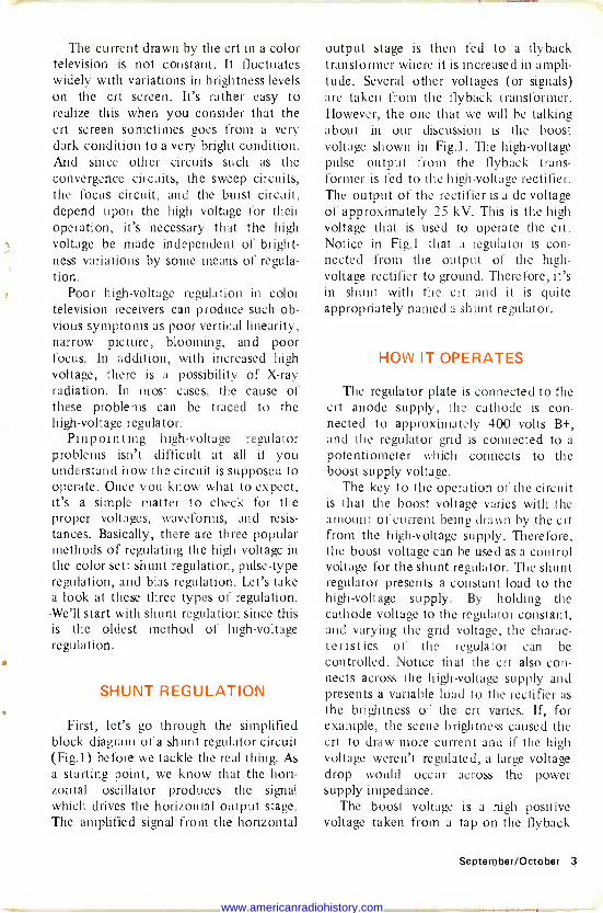
The current drawn by the crt in a color television is not constant. It fluctuates widely with variations in brightness levels on the crt screen. It's rather easy to realize this when you consider that the crt screen sometimes goes from a very dark condition to a very bright condition. And since other circuits such as the convergence circuits, the sweep circuits, the focus circuit, and the burst circuit, depend upon the high voltage for their operation, it's necessary that the high voltage be made independent of bright- ness variations by some means of regula- tion.
Poor high -voltage regulation in color television receivers can produce such ob- vious symptoms as poor vertical linearity, narrow picture, blooming, and poor focus. In addition, with increased high voltage, there is a possibility of X-ray radiation. In most cases, the cause of these problems can be traced to the high -voltage regulator.
Pinpointing high -voltage regulator problems isn't difficult at all if you understand how the circuit is supposed to operate. Once you know what to expect, it's a simple matter to check for the proper voltages, waveforms, and resis- tances. Basically, there are three popular methods of regulating the high voltage in the color set: shunt regulation, pulse -type regulation, and bias regulation. Let's take a look at these three types of regulation. -We'll start with shunt regulation since this is the oldest method of high -voltage regulation.
SHUNT REGULATION
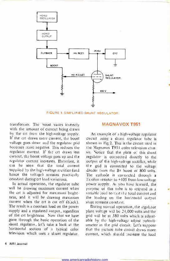
First, let's go through the simplified block diagram of a shunt regulator circuit (Fig.1) before we tackle the real thing. As a starting point, we know that the hori- zontal oscillator produces the signal which drives the horizontal output stage. The amplified signal from the horizontal
output stage is then fed to a flyback transformer where it is increased in ampli- tude. Several other voltages (or signals) are taken from the flyback transformer. However, the one that we will be talking about in our discussion is the boost voltage shown in Fig.1. The high -voltage pulse output from the flyback trans- former is fed to the high -voltage rectifier. The output of the rectifier is a dc voltage of approximately 25 kV. This is the high voltage that is used to operate the crt. Notice in Fig.1 that a regulator is con- nected from the output of the high - voltage rectifier to ground. Therefore, it's in shunt with the crt and it is quite appropriately named a shunt regulator.
HOW IT OPERATES
The regulator plate is connected to the crt anode supply, the cathode is con- nected to approximately 400 volts B+, and the regulator grid is connected to a
potentiometer which connects to the boost supply voltage.
The key to the operation of the circuit is that the boost voltage varies with the amount of current being drawn by the crt from the high -voltage supply. Therefore, the boost voltage can be used as a control voltage for the shunt regulator. The shunt regulator presents a constant load to the high -voltage supply. By holding the cathode voltage to the regulator constant, and varying the grid voltage, the charac- teristics of the regulator can be controlled. Notice that the crt also con- nects across the high -voltage supply and presents a variable load to the rectifier as the brightness of the crt varies. If, for example, the scene brightness caused the crt to draw more current and if the high voltage weren't regulated, a large voltage drop would occur across the power supply impedance.
The boost voltage is a high positive voltage taken from a tap on the flyback
September/October 3
www.americanradiohistory.com
HORIZ OSCILLATOR
HORIZ OUTPUT
F LYBACK
BOOST
HV RECT
HV ADJUST
25 KV CRT
SHUNT REGULATOR
400V
FIGURE 1. SIMPLIFIED SHUNT REGULATOR.
transformer. The boost varies inversely with the amount of current being drawn by the crt from the high -voltage supply. If the crt draws more current, the boost voltage goes down and the regulator grid becomes more negative. This reduces the regulator current. If the crt draws less current, the boost voltage goes up and the regulator current increases. Therefore, it can be seen that the total current supplied by the high -voltage rectifier (and hence the voltage) remains practically constant during crt load variations.
In actual operation, the regulator tube will be drawing minimum current when the crt is adjusted for maximum bright- ness, and it will be drawing maximum current when the crt is cut off (black). The result is a constant load on the power supply and a regulated output, regardless of the crt brightness. Now that we have gone through the basic operation of the shunt regulator, let's take a look at the horizontal section of a typical color television which uses a shunt regulator.
MAGNAVOX T951
An example of a high -voltage regulator circuit using a shunt regulator tube is shown in Fig.2. This is the circuit used in the Magnavox T951 color television chas- sis. Notice that the plate of this shunt regulator is connected directly to the output of the high -voltage rectifier, while the grid is connected to the voltage divider from the B+ boost of 800 volts. The cathode is connected through a 1k -ohm resistor to +405 from low -voltage power supply. As you have learned, the purpose of this tube is to respond as a variable load so that the total current and the loading on the horizontal output stage remains constant.
During normal operation, the regulator plate voltage will be 24,000 volts and the grid will be at 380 volts which is adjust- able by the high -voltage adjust potenti- ometer in the grid circuit. Let's suppose that the picture tube circuit draws more current, which should increase the load
4 NRI Journal
www.americanradiohistory.com
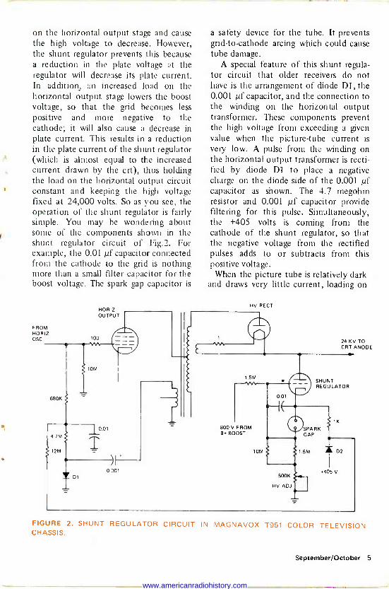
on the horizontal output stage and cause the high voltage to decrease. However, the shunt regulator prevents this because a reduction in the plate voltage at the regulator will decrease its plate current. In addition, an increased load on the horizontal output stage lowers the boost voltage, so that the grid becomes less positive and more negative to the cathode; it will also cause a decrease in plate current. This results in a reduction in the plate current of the shunt regulator (which is almost equal to the increased current drawn by the crt), thus holding the load on the horizontal output circuit constant and keeping the high voltage fixed at 24,000 volts. So as you see, the operation of the shunt regulator is fairly simple. You may be wondering about some of the components shown in the shunt regulator circuit of Fig.2. For example, the 0.01 µf capacitor connected from the cathode to the grid is nothing more than a small filter capacitor for the boost voltage. The spark gap capacitor is
F ROM HORIZ OSC
680K
4.7M
12M
HORIZ OUTPUT
100
1,-
j_00,
T
01 0.001
ì E
a safety device for the tube. It prevents grid -to -cathode arcing which could cause tube damage.
A special feature of this shunt regula- tor circuit that older receivers do not have is the arrangement of diode Dl, the 0.001 µf capacitor, and the connection to the winding on the horizontal output transformer. These components prevent the high voltage from exceeding a given value when the picture -tube current is very low. A pulse from the winding on the horizontal output transformer is recti- fied by diode D1 to place a negative charge on the diode side of the 0.001 pf capacitor as shown. The 4.7 megohm resistor and 0.001 pf capacitor provide filtering for this pulse. Simultaneously, the +405 volts is coming from the cathode of the shunt regulator, so that the negative voltage from the rectified pulses adds to or subtracts from this positive voltage.
When the picture tube is relatively dark and draws very little current, loading on
HV RECT
24 KV TO CRT ANODE
800 V FROM B BOOST
10M
SHUNT REGULATOR
0.01
500K
HV ADJ
SPARK GAP
1.5M D2
.405 V
FIGURE 2. SHUNT REGULATOR CIRCUIT IN MAGNAVOX T951 COLOR TELEVISION CHASSIS.
September/October 5
www.americanradiohistory.com
Cl
HORIZONTAL OUTPUT
HORIZONTAL OSCILLATOR
0.01
RI R2 27K 22K
282 V
R10 8.2K
282 V
TO HIGH.VOLTAGE TRIPLER
DAMPER AND DEFLECTION COILS
IllTO AFC AND AGO
FIGURE 3. HIGH -VOLTAGE REGULATOR CIRCUIT OF SYLVANIA COLOR TELEVISION CHASSIS.
the horizontal output circuits is at its lowest so that the pulse to be rectified is
at its greatest amplitude. The negative voltage that is produced, when added to the positive cathode voltage of the regula- tor, causes the grid of the horizontal output tube to go in a negative direction. This increased negative grid voltage re- duces the horizontal output, therefore limiting the high voltage.
As I said earlier, shunt regulators were the first type of regulator used in color TV receivers, and it was soon discovered that they had some undesirable features. Since the shunt regulator tube is con- nected across the high -voltage output, it must withstand the high voltage. There- fore, it is prone to arcing between its plate, grid, cathode, and filament. It also adds additional current loading to the horizontal output circuit. The high volt- ages it must handle make it a source of unwanted X-rays. Most of the dis- advantages of the shunt regulator have been overcome by using a feedback method of regulation which we will dis- cuss next.
THE SYLVANIA D16-2
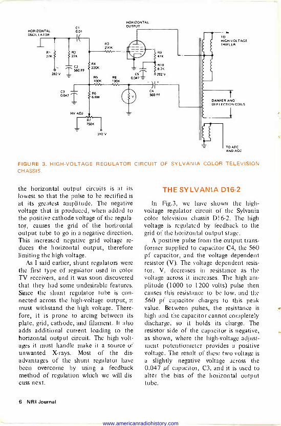
In Fig.3, we have shown the high - voltage regulator circuit of the Sylvania color television chassis D16-2. The high voltage is regulated by feedback to the grid of the horizontal output stage.
A positive pulse from the output trans- former supplied to capacitor C4, the 560 pf capacitor, and the voltage dependent resistor (V). The voltage dependent resis- tor, V, decreases in resistance as the voltage across it increases. The high am- plitude (1000 to 1200 volts) pulse then causes this resistance to be low, and the 560 pf capacitor charges to this peak value. Between pulses, the resistance is high and the capacitor cannot completely discharge, so it holds its charge. The resistor side of the capacitor is negative, as shown, where the high -voltage adjust- ment potentiometer provides a positive voltage. The result of these two voltage is a slightly negative voltage across the 0.047 µf capacitor, C3, and it is used to alter the bias of the horizontal output tube.
6 NRI Journal
www.americanradiohistory.com

GRID BIAS CHANGES IN STEP
WITH DROP ACROSS R114 ( AND SETTING OF HV CONTROL )
HOR1Z OUTPUT 24JE6
3 KV PULSE
PULSE 1 0402 REG T
ISPF 17KV6 < R402
1100
CR 401 AL DAMPER
NOMINAL VOLTAGE `
APPROX 240v
E NT WK 100V
35A K
10K R401 680
YOKE Yeti
T 200V
o'
C409 001 = B BOOST
SOURCE T
`
07 700 V
DK
14V ADJ SOOK R406
R408 560K
i R411 270K
5%
HV RE C T
3A3A
O O SECONDARY
b
BE AM CURRENT
21 5 Kv
7O0 v0 ZERO CURRENT 430v 1000 go VOLTAGE DROP VARIES IN STEP WITH BEAM CURRENT DEMAND
Courtesy RCA
FIGURE 4. SIMPLIFIED PULSE REGULATOR SYSTEM.
If, for some reason, the high voltage for the picture tube decreases, (because the picture tube is drawing the high current and loading down the horizontal output stage), the pulse supplied to the 560 pf capacitor will be smaller. The capacitor will then charge less, resulting in less negative voltage to cancel the positive voltage across C3. This means the grid of the horizontal output tube will be less negative so it can provide more drive and a greater output to the transformer. Circuit regulation is therefore achieved without the shunt regulator tube and its many disadvantages. The high -voltage adjust potentiometer permits setting the output grid bias for the high -voltage output specified by the manufacturer.
PULSE REGULATION
The third type of high -voltage regula- tion that we will discuss is pulse regula-
tion. The RCA CTC22 was one of the first color sets that I noticed using pulse regulation. Let's discuss the operation of the CTC22 horizontal output stage and we will see how pulse regulation is
achieved. As we did with shunt regula- tion, let's use a simplified diagram as
shown in Fig.4. As you can see from the simplified diagram, the pulse regulator is
connected in the primary section of the flyback transformer. It is the constant loading and unloading of the pulse regula- tor on the flyback primary winding that controls the high voltage.
To do a good job of regulating the high voltage, the pulse regulator tube must draw more ac current from the horizontal output transformer when the high -voltage rectifier is drawing less, thus maintaining a constant load on the sweep circuit and stabilizing the high voltage. This circuit is unusual because the regulator control is achieved by sampling the picture tube current by means of a special winding on
September/October 7
www.americanradiohistory.com
the flyback and using the resultant volt- age drop which is developed across the resistor to control the regulator grid circuit.
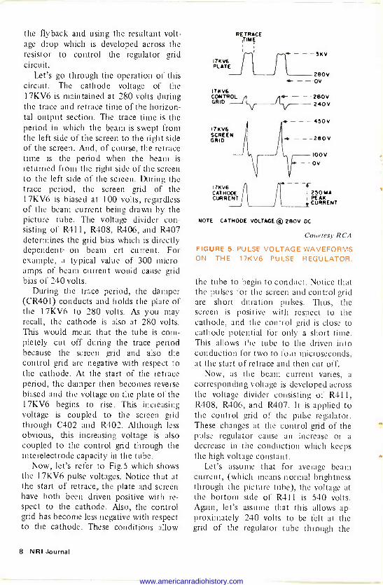
Let's go through the operation of this circuit. The cathode voltage of the 17KV6 is maintained at 280 volts during the trace and retrace time of the horizon- tal output section. The trace time is the period in which the beam is swept from the left side of the screen to the right side of the screen. And, of course, the retrace time is the period when the beam is returned from the right side of the screen to the left side of the screen. During the trace period, the screen grid of the 17KV6 is biased at 100 volts, regardless of the beam current being drawn by the picture tube. The voltage divider con- sisting of R411, R408, R406, and R407 determines the grid bias which is directly dependent- on beam crt current. For example, a typical value of 300 micro - amps of beam current would cause grid bias of 240 volts.
During the trace period, the damper (CR401) conducts and holds the plate of the 17KV6 to 280 volts. As you may recall, the cathode is also at 280 volts. This would mean that the tube is com- pletely cut off during the trace period because the screen grid and also the control grid are negative with respect to the cathode. At the start of the retrace period, the damper then becomes reverse biased and the voltage on the plate of the 17KV6 begins to rise. This increasing voltage is coupled to the screen grid through C402 and R402. Although less obvious, this increasing voltage is also coupled to the control grid through the interelectrode capacity in the tube.
Now, let's refer to Fig.5 which shows the 17KV6 pulse voltages. Notice that at the start of retrace, the plate and screen have both been driven positive with re- spect to the cathode. Also, the control grid has become less negative with respect to the cathode. These conditions allow
RETRACE TIE
- - 3KV 17K V6 PLATE
280V - - ov
17KV6 CONTROL / - 280V GRID . -- 240V
-- - - 450V 17KV6 SCREEN GRID - - -280V
17K V6 CATHODE CURRENT
---100v - -Ov
- - - I 250 MA I PEAK
CURRENT
NOTE CATHODE VOLTAGE ® 280v DC
Courtesy RCA
FIGURE 5. PULSE VOLTAGE WAVEFORMS ON THE 17KV6 PULSE REGULATOR.
the tube to begin to conduct. Notice that the pulses for the screen and control grid are short duration pulses. Thus, the screen is positive with respect to the cathode, and the control grid is close to cathode potential for only a short time. This allows the tube to the driven into conduction for two to four microseconds, at the start of retrace and then cut off.
Now, as the beam current varies, a corresponding voltage is developed across the voltage divider consisting of R411, R408, R406, and R407. It is applied to the control grid of the pulse regulator. These changes at the control grid of the pulse regulator cause an increase or a decrease in the conduction which keeps the high voltage constant.
Let's assume that for average beam current, (which means normal brightness through the picture tube), the voltage at the bottom side of R41 1 is 540 volts. Again, let's assume that this allows ap- proximately 240 volts to be felt at the grid of the regulator tube through the
8 NRI Journal
www.americanradiohistory.com
HORIZ OUTPUT 24JE6A
TO HORIZ YOKE
WINDINGS
PULSE TO ADC AND BLANKER
4
B BOOST SOURCE
TO 3A3Á PLATE
PULSE 5 TO KILLER
AND BURST AMP
O Ç l CONVERGENCE
o PULSE
17KV6 PULSE RE
360K
270K
.01
NV ADJ 500K
390K
DAMPER
9
IS
roo
ee
22
NORIZ. EFF.
33K
ó O
- O TO
MER SEVERAL
(VIA YOKE
STASES SOCKET)
2B0V 2BOVi
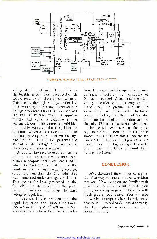
FIGURE 6. HORIZONTAL DEF LECTION-CTC22.
voltage divider network. Then, let's say the brightness of the crt is reduced which would tend to off the crt beam current. This means the high voltage, under less load, would try to increase. However, the voltage drop across 8411 is decreased and the full B+ voltage, which is approxi- mately 700 volts, is available at the voltage divider. This causes less grid bias or a positive -going signal at the grid of the regulator, which causes its conduction to increase, placing more load on the fly- back pulse. This action prevents the second anode voltage from increasing; therefore, regulation is achieved.
Of course, the reverse occurs when the picture tube load increases. Beam current causes a proportional drop across R411 which supplies the control grid of the regulator with a negative -going voltage, something less than the 240 volts that was mentioned under average conditions. This means the load presented to the flyback pulse decreases and the pulse tends to increase and again the high voltage is regulated.
In essence, it can be seen that the regulating action is continuous and simul- taneous in this type of system. Certain advantages are achieved with pulse regula-
tion. The regulator tube operates at lower voltages; therefore, the possibility of X-rays is reduced. Also, since the high - voltage rectifier conducts only on de- mand from the picture tube, its life expectancy is prolonged. Reduced operating voltages at the regulator also eliminate the need for shielding around the tube. This is a space saving advantage.
The actual schematic of the pulse regulator circuit used in the CTC22 is shown in Fig.6. From this schematic, we can see from the various signals that are taken from the high -voltage (flyback) circuit the importance of good high - voltage regulation.
CONCLUSION
We've discussed three types of regula- tion that may be found in color television receivers. Now that you are familiar with how these particular circuits operate, you should tackle repair jobs of this type with much greater confidence. You will also know what to expect when the brightness control is increased or decreased to varify that the high -voltage circuits are func- tioning properly.
September/October 9
www.americanradiohistory.com
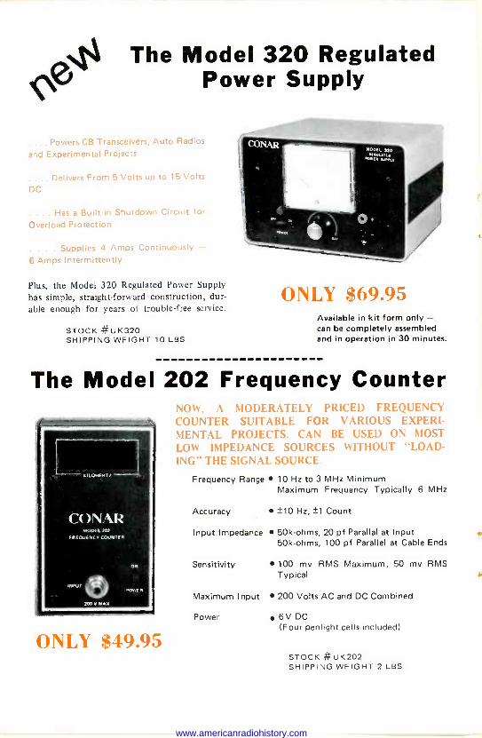
Ni4 The Model 320 Regulated Power Supply
.... Powers CB Transceivers, Auto Radios
and Experimental Projects
.... Delivers From 5 Volts up to 15 Volts DC
. ... Has a Built-in Shutdown Circuit for
Overload Protection
. . . Supplies 4 Amps Continuously 6 Amps Intermittently
Plus, the Model 320 Regulated Power Supply has simple, straight -forward construction, dur- able enough for years of trouble -free service.
STOCK #UK320 SHIPPING WEIGHT 10 LBS.
ONLY $69.95 Available in kit form only - can be completely assembled and in operation in 30 minutes.
The Model 202 Frequency Counter NOW, A MODERATELY PRICED FREQUENCY
N COUNTER SUITABLE FOR VARIOUS EXPERI- MENTAL PROJECTS. CAN BE USED ON MOST
LOW IMPEDANCE SOURCES WITHOUT "LOAD- ING" THE SIGNAL SOURCE.
Frequency Range 10 Hz to 3 MHz Minimum Maximum Frequency Typically 6 MHz
Accuracy ±10 Hz, ±1 Count
Input Impedance 50k -ohms, 20 pf Parallal at Input 50k -ohms, 100 pf Parallel at Cable Ends
KILOHERTZ
CO`.R MODEL 202
EREOUENCV COUNTER
ON Sensitivity 100 my RMS Maximum, 50 my RMS Typical
POWER
Maximum Input 200 Volts AC and DC Combined 11rrwK
6V DC Power (Four penlight cells included(
ONLY $49.95 STOCK #ÚK202 SHIPPING WEIGHT 2 LBS.
www.americanradiohistory.com
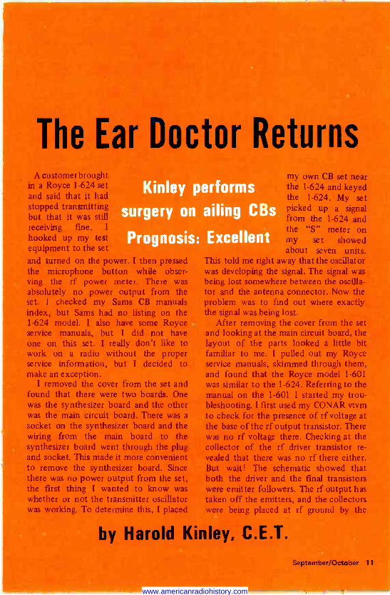
The Ear A customer brought
in a Royce 1-624 set and said that it had stopped transmitting ut that it was still eceiving fine. I
hooked up my test equipment to the set
and turned on the power. I then pressed the microphone button while obser- ving the rf power meter. There was absolutely no power output from the set. I checked my Sams CB manuals index, but Sams had no listing on the 1-624 model. I also have some Royce service manuals, but I did not have one on this set. I really don't like to work on a radio without the proper service information, but I decided to make an exception.
I removed the cover from the set and found that there were two boards. One was the synthesizer board and the other was the main circuit board. There was a
socket on the synthesizer board and the wiring from the main board to the synthesizer board went through the plug and socket. This made it more convenient to remove the synthesizer board. Since there was no power output from the set, the first thing I wanted to know was whether or not the transmitter oscillator was working. To determine this, I placed
i oc Returns
Kinley performs
surgery on ailing CB
Prognosis: Excellen
my own CB set near the 1-624 and keyed the 1-624. My set picked up a signal from the 1-624 and the "S" meter on my set showed about seven units.
his told me right away that the oscillator was developing the signal. The signal was being lost somewhere between the oscilla- tor and the antenna connector. Now the problem was to find out where exactly the signal was being lost.
After removing the cover from the set and looking at the main circuit board, the layout of the parts looked a little bit familiar to me. I pulled out my Royce service manuals, skimmed through them, and found that the Royce model 1-601 was similar to the 1-624. Referring to the manual on the 1-601 I started my trou- bleshooting. I first used my CONAR vtvm to check for the presence of rf voltage at the base of the rf output transistor. There was no rf voltage there. Checking at the collector of the rf driver transistor re- vealed that there was no rf there either. But wait! The schematic showed that both the driver and the final transistors were emitter followers. The rf output has taken off the emitters, and the collectors were being placed at rf ground by the
by Harold Kinley, C.E.T.
September/October 11
www.americanradiohistory.com
bypass capacitors. This is just a little unusual in that the vast majority of CB manufacturers use the common emitter configuration, in which the output is
taken from the collector. Now I checked for rf voltage at the emitter of both the driver and the rf output transistor. Still there was no measurable rf.
I removed the rf amplifier/buffer tran- sistor and checked it. It checked fine so I
put it back into the radio and took a few minutes to do some headscratching. The set had all the symptoms of a missing oscillator signal, but I had already con- firmed that the oscillator was working. I
admit I was a little baffled at this point and I was not sure what my next step should be. After some more thought, I
decided to feed the output from my signal generator to the base of the rf amplifier/buffer transistor.
I turned the CB generator to Channel 19 and turned the output to maximum. I coupled the signal to the base of the transistor through a 0.001 pf capacitor. With this signal fed into the base of the rf amplifier/buffer transistor, I keyed the transmitter and, to my surprise, the power meter read 3.5 watts. Now I was getting somewhere. This told me that the oscillator signal was not getting to the
base of the rf amplifier/buffer transistor. Since I had already confirmed that the oscillator was working, there had to be an interruption in the signal path from the oscillator to the base of the rf amplifier/ buffer.
Tracing the wiring, I found that a
shielded wire came from the oscillator board to the transmitter input on the main board. This shielded wire connected to the oscillator board through a plug and socket, as I mentioned before. I thought perhaps there might be a bad connection in the plug so I keyed the transmitter and wiggled the plug. The power came up and then disappeared again as the plug was wiggled. By placing pressure on the plug a certain way, the power output would remain steady. But when the pres- sure was removed from the plug, the output would disappear again.
I decided to use the signal generator again to check the plug and socket connection. I fed the signal generator output to the point on the synthesizer board which connects to the shielded wire coming from the transmitter input. Now with the transmitter keyed, the output remained steady. This cleared the plug and socket connections. There ap- parently was a bad connection some -
12 NRI Journal
www.americanradiohistory.com
where on the synthesizer board. By placing pressure on the plug and socket, the board was apparently distorted enough to make a good connection.
The board would have to be removed to get to the foil side to reheat the solder connections. Removing the board was not at all difficult. I removed the plug, three screws, and the channel selector knob. Then I was able to flip the board over to get to the solder connections. I examined the board very carefully but was not able to locate any potentially bad connec- tions. I decided to reheat all the connections in the vicinity of where the oscillator unit connects to the board.
After doing this, 1 reassembled the board to the chassis. I keyed the trans- mitter and the output was 3.5 watts and steady. This time wiggling the plug had no affect on the power output. I didn't know which connection was bad, but I
had apparently hit on the right one. I
checked the set out thoroughly before reassembling it. After I was satisfied that the repair was good, I reassembled the set into the cabinet. There were no parts involved in the repair job so the only charge was $12.50 for labor. The com- plete repair job took less than one hour so I still came out okay.
BON SONIC CB 23
The owner said that he had lent his set to someone who he thought had hooked up the power connections backwards. The set would pop fuses instantly. At present the highest Sams manual that I
had was # 114 and there wasn't a listing for the Bon Sonic set in the Sams index. I
thumbed through the latest Sams manuals that I had until I came across one with a picture of a set on the cover that looked very similar to the Bon Sonic. The set was a RYSTL CBR-1800. I removed the cover from the Bon Sonic and compared the parts layout and circuit board detail to
the RYSTL shown in the Sams No.104 CB manual. The sets were identical.
The first thing that I noticed was that the red wire that connects the input line filter choke to the on -off switch, had the insulation melted off of it. Also, a red wire which leads from the switch to the circuit board was in the same condition. I
replaced these wires before doing any checking with the ohmmeter. After re- placing these wires, I checked the resis- tance across the power input terminals. It measured a low 0.2 ohm. I looked at the schematic and noticed that this set has a polarity protection -diode across the hot line to ground. I removed the diode and it fell apart in my hands. With the diode out, I now rechecked the resistance across the power input and the short was gone. I
replaced the diode before going any further.
After replacing the diode, I applied power to the set to see if it would work. The lights came on. I turned the squelch open and the volume up, but there was only a very slight sound from the speaker. I had the signal generator feeding a
modulated signal into the set, but this was not coming through at all. There was only a very slight hiss. The level on the signal that I had fed into the set was around 3 microvolts, but there was no indication on the radio's "S" meter.
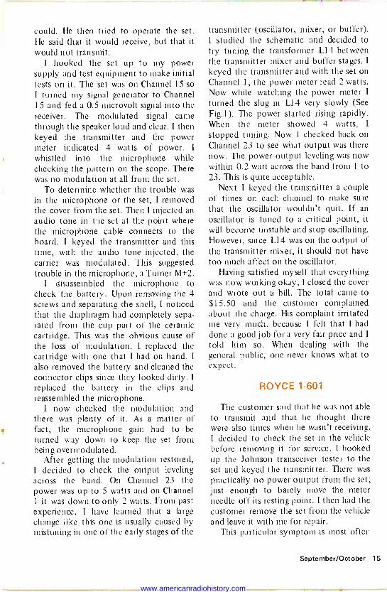
I was examining the circuit board when I accidentally jarred the set. When the set was jarred, the modulated signal came through the speaker. Using a screwdriver handle, I started tapping lightly on the circuit board until I reached an area on the board more sensitive to the tapping. I
turned the set over to the component side of the board and wiggled various compo- nents with an insulated tuning tool. I
found that wiggling the first 455 kHz i -f transformer seemed to have the greatest affect. I turned the power off and re-
heated the connections around the trans- former. I turned the set back on and now the intermittent was gone. The receiver
September/October 13
www.americanradiohistory.com
TAPP/Ne T7,:e. P. G . ZiaARI7 rr-) A.e-e.g.
worked properly now. Then I turned my attention to the
transmitter. I keyed the transmitter to check it out. The power meter registered 4 watts. The frequency counter showed the signal to be on frequency. I whistled into the microphone, but the scope showed no modulation at all. Since I had the set out of the cabinet, I injected an audio tone at the microphone socket on the chassis. Now, with the transmitter keyed, the scope showed modulation
present on the carrier. The trouble had to be in the microphone itself.
I disassembled the microphone and injected an audio tone across the micro- phone cartridge. With the transmitter keyed, the scope showed modulation present. This pointed to the cartridge as
the defective part. I removed it and installed a new one and this brought the modulation back to the transmitter. I
reassembled the microphone and this completed the repairs.
Before replacing the cover on the set, I
ran a complete check on the receiver and transmitter to make sure that everything was working okay. Everything checked out fine now. The last thing that I did was to get an on the air check on my shop antenna. After receiving good reports on the set, I replaced the cover and wrote out the repair bill. The total cost of the repairs came to $24.50.
BOBCAT 23B
A customer brought in a Pearce Simpson Bobcat 23B and explained that the car in which this set was installed was involved in an accident. The radio fell out of the car and into a ditch. He said that a
little mud and water had gotten into the set and that he had cleaned out what he
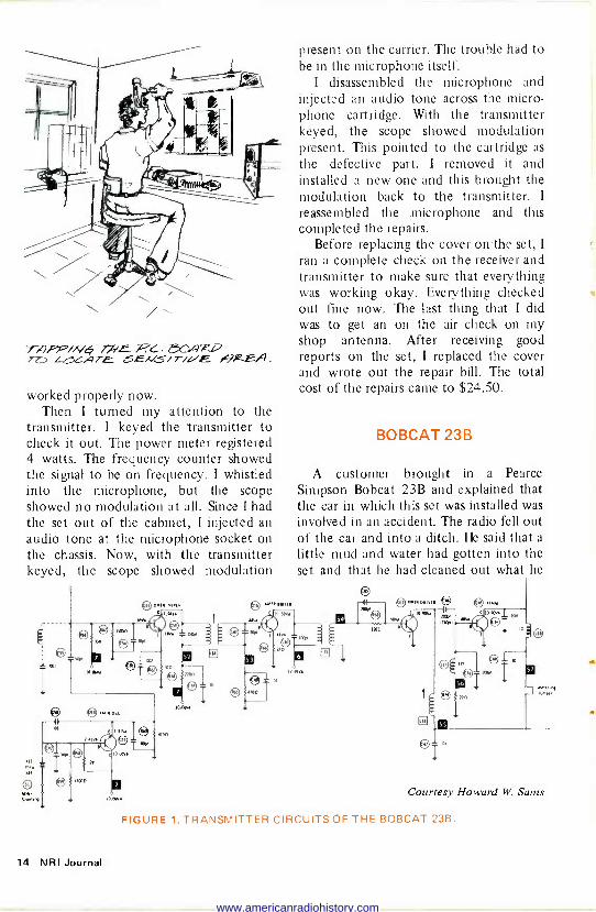
Courtesy Howard W. Sams
FIGURE 1. TRANSMITTER CIRCUITS OF THE BOBCAT 23B.
14 NRI Journal
www.americanradiohistory.com
could. He then tried to operate the set. He said that it would receive, but that it would not transmit.
I hooked the set up to my power supply and test equipment to make initial tests on it. The set was on Channel 15 so I turned my signal generator to Channel 15 and fed a 0.5 microvolt signal into the receiver. The modulated signal came through the speaker loud and clear. I then keyed the transmitter and the power meter indicated 4 watts of power. I
whistled into the microphone while checking the pattern on the scope. There was no modulation at all from the set.
To determine whether the trouble was in the microphone or the set, I removed the cover from the set. Then I injected an audio tone in the set at the point where the microphone cable connects to the board. I keyed the transmitter and this time, with the audio tone injected, the carrier was modulated. This suggested trouble in the microphone, a Turner M+2.
I disassembled the microphone to check the battery. Upon removing the 4 screws and separating the shell, I noticed that the diaphragm had completely sepa- rated from the cup part of the ceramic cartridge. This was the obvious cause of the loss of modulation. I replaced the cartridge with one that I had on hand. I
also removed the battery and cleaned the connector clips since they looked dirty. I
replaced the battery in the clips and reassembled the microphone.
I now checked the modulation and there was plenty of it. As a matter of fact, the microphone gain had to be turned way down to keep the set from being overmodulated.
After getting the modulation restored, I decided to check the output leveling across the band. On Channel 23 the power was up to 5 watts and on Channel 1 it was down to only 2 watts. From past experience, I have learned that a large change like this one is usually caused by mistuning in one of the early stages of the
transmitter (oscillator, mixer, or buffer). I studied the schematic and decided to try tuning the transformer L14 between the transmitter mixer and buffer stages. I
keyed the transmitter and with the set on Channel 1, the power meter read 2 watts. Now while watching the power meter I
turned the slug in L14 very slowly (See Fig.l ). The power started rising rapidly. When the meter showed 4 watts, I
stopped tuning. Now I checked back on Channel 23 to see what output was there now. The power output leveling was now within 0.2 watt across the band from 1 to 23. This is quite acceptable.
Next I keyed the transmitter a couple of times on each channel to make sure that the oscillator wouldn't quit. If an oscillator is tuned to a critical point, it
will become unstable and stop oscillating. However, since L14 was on the output of the transmitter mixer, it should not have too much affect on the oscillator.
Having satisfied myself that everything was now working okay, I closed the cover and wrote out a bill. The total came to $15.50 and the customer complained about the charge. His complaint irritated me very much, because I felt that I had done a good job fora very fair price and I
told him so. When dealing with the general public, one never knows what to expect.
ROYCE 1-601
The customer said that he was not able to transmit and that he thought there were also times when he wasn't receiving. I decided to check the set in the vehicle before removing it for service. I hooked up the Johnson transceiver tester to the set and keyed the transmitter. There was practically no power output from the set; just enough to barely move the meter needle off its resting point. I then had the customer remove the set from the vehicle and leave it with me for repair.
This particular symptom is most often
September/October 15
www.americanradiohistory.com
caused by a bad rf output transistor in the transmitter. This, in turn, is often caused by a defect in the antenna system causing a high SWR on the transmission line. A high SWR on the coax line will shorten the life of an output transistor considerably. As a matter of good prac- tice, I always inform the customer that he should have his antenna checked after replacing an output transistor in his radio. If he is not willing to have his antenna checked, I will not guarantee the new output transistor, not even for a minute.
I pulled the cover from the set and removed the rf output transistor to check it. It was defective and I replaced it with an ECG195A Sylvania replacement. I then hooked up the set and keyed the transmitter to check the power output. On Channel 23 the output was 2 watts and on Channel 1 the output was 1 watt. I tuned the driver transformer and was able to even up the output across the band to 3.5 watts. I then checked the modulation and there was no modulation at all. I checked for audio output from the receiver and there was none.
I started my troubleshooting by the signal tracing method. I fed a 50 micro- volt modulated signal into the receiver and checked for the signal at the top end of the volume control (high side). The signal came through the tracer loud and
2515í6K AUDIO AMP
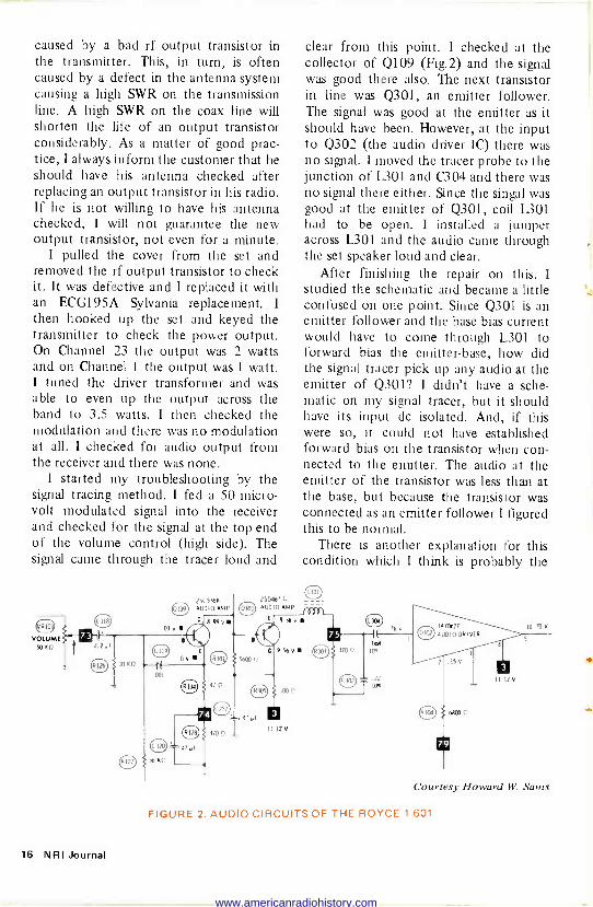
clear from this point. I checked at the collector of Q109 (Fig.2) and the signal was good there also. The next transistor in line was Q301, an emitter follower. The signal was good at the emitter as it should have been. However, at the input to Q302 (the audio driver IC) there was no signal. I moved the tracer probe to the junction of L301 and C304 and there was no signal there either. Since the singal was good at the emitter of Q301, coil L301 had to be open. I installed a jumper across 1301 and the audio came through the set speaker loud and clear.
After finishing the repair on this, I studied the schematic and became a little confused on one point. Since Q301 is an emitter follower and the base bias current would have to come through L301 to forward bias the emitter -base, how did the signal tracer pick up any audio at the emitter of Q301? I didn't have a sche- matic on my signal tracer, but it should have its input dc isolated. And, if this were so, it could not have established forward bias on the transistor when con- nected to the emitter. The audio at the emitter of the transistor was less than at the base, but because the transistor was connected as an emitter follower I figured this to be normal.
There is another explanation for this condition which I think is probably the
250467 C _ _ AUDIO AMP --
Courtesy Howard W. Sams
FIGURE 2. AUDIO CIRCUITS OF THE ROYCE 1-601.
16 NRI Journal
www.americanradiohistory.com
right one. The emitter -bese junction could have been acting like a diode between the signal tracer and the collec- tor of transistor Q109. To vertify this, I did a bit of experimenting. I connected my signal tracer to my tone generator and noted the volume from the tracer. Then I
connected a diode between the tone generator and the signal tracer. The tone still came through, though not as loudly. To go a step further, I used an audio transistor and connected the emitter -base junction between the tracer and the tone generator. The results were the same. This seemed to explain why the signal was present at the emitter of the emitter follower even though the coil was open.
Before considering the repairs com- plete, I checked the modulation. It was good now also. I replaced the cover on the set. The next day the customer came by to get the radio and at that time I
checked the antenna on his car. It was a standard base -loaded antenna mounted on the trunk lid of the car. The SWR checked around 6:1 on Channel 1 and around 5:1 on Channel 23. I loosened the set screw on the whip and pulled it up as high as it could be extended and re - tightened the screw. Then I rechecked the SWR and this time it was 2:1 on Channel 23 and increased to 3:1 on Channel 1. This indicated that the whip was still too short, but there was no mote adjustment left. He said that he only used Channel 19 and since the SWR was only a little above 2:1 on 19, I told him it Would probably be okay to use the antenna like it was. The entire charge came to $29.30.
JOHNSON MESSENGER 123
The complaint on this set was that it would not transmit or receive at all. I
hooked up my test instruments to the set and applied power. I turned the volume up and opened the squelch. There was some receiver hiss coming from the speak- er. I fed a modulated signal into the set,
but the signal wasn't getting through to the speaker and there was no indication on the "S" meter. I keyed the transmitter, but the rf power meter showed no power output at all. In order to determine if the synthesizer/oscillator was functioning, I
placed my own CB near the 123 and keyed the 123 while watching the "S" meter on my set. My set wouldn't pick up any sig- nal from the 123 so apparently the syn- thesizer oscillator section was not func- tioning properly. The trouble symptoms were the same on all channels.
I removed the cover from the 123 and pondered over what I should do first. I
figured that one of the oscillators was dead. Before I get into my trouble- shooting procedure, I feel that a descrip- tion of the general operation of the synthesizer circuit is in order. In the receive condition, a frequency from the local oscillator is mixed with a frequency from the synthesizer oscillator to yield a difference frequency at the output of the synthesizer mixer. This frequency would be 455 kHz lower than the channel frequency in the receive condition. This is necessary to obtain the 455 kHz i -f frequency in the receiver. In the transmit mode, the frequency at the synthesizer output would have to be equal to the channel frequency. Therefore, a different crystal is switched into the local oscillator circuit when the transmitter is keyed. Let's take the example of Channel 22. In the synthesizer oscillator, the 32.950 MHz crystal is selected. In the receive condition, we would need a frequency which is 455 kHz lower than the channel frequency at the synthesizer mixer out- put. For Channel 22 (27.225 MHz) we would need a frequency at 26.770 MHz, (27.225 - 0.455 = 26.770). To obtain the 26.770 MHz signal, the 32.950 MHz signal is mixed with a 6.180 MHz signal from the local oscillator to yield a dif- ference frequency 26.770 MHz al the synthesizer output. This 26.770 MHz signal is then mixed with the incoming
September/October 17
www.americanradiohistory.com
27.225 MHz signal in the receiver mixer to give the 455 kHz i -f signal. In the transmit mode, we want the synthesizer output frequency to equal the channel frequency. Therefore, a different crystal is switched into the local oscillator circuit in the transmit mode. The high oscillator fre- quency remains the same (32.950 MHz).
In the transmit mode, a 5.735 MHz crystal is switched into the local oscillator circuit. This is then mixed with the 32.950 MHz signal in the synthesizer mixer to yield the difference frequency 27.225 MHz, (32.950 - 5.735 = 27.225). This is the correct channel frequency. This frequency is then amplified in following stages and fed to the antenna.
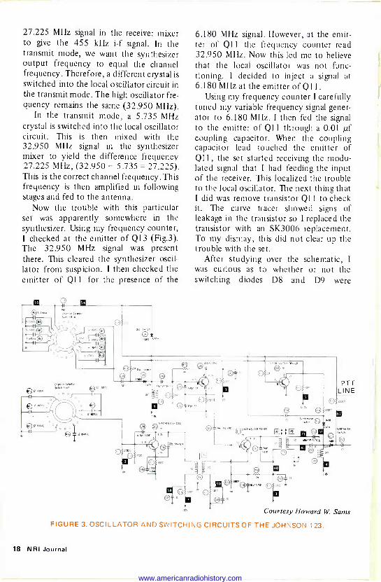
Now the trouble with this particular set was apparently somewhere in the synthesizer. Using my frequency counter, I checked at the emitter of Q13 (Fig.3). The 32.950 MHz signal was present there. This cleared the synthesizer oscil- lator from suspicion. I then checked the emitter of Ql I for the presence of the
,..t. P`" v PA,
--tF
6.180 MHz signal. However, at the emit- ter of Q11 the frequency counter read 32.950 MHz. Now this led me to believe that the local oscillator was not func- tioning. I decided to inject a signal at 6.180 MHz at the emitter of Q11.
Using my frequency counter I carefully tuned my variable frequency signal gener- ator to 6.180 MHz. I then fed the signal to the emitter of Q11 through a 0.01 pf coupling capacitor. When the coupling capacitor lead touched the emitter of Q11, the set started receiving the modu- lated signal that I had feeding the input of the receiver. This localized the trouble to the local oscillator. The next thing that I did was remove transistor Q11 to check it. The curve tracer showed signs of leakage in the transistor so I replaced the transistor with an SK3006 replacement. To my dismay, this did not clear up the trouble with the set.
After studying over the schematic, I
was curious as to whether or not the switching diodes D8 and D9 were
O: I
10,
O Cr"'""`
n
200
PTT LINE
Courtesy Howard W. Sams
FIGURE 3. OSCILLATOR AND SWITCHING CIRCUITS OF THE JOHNSON 123.
18 NRI Journal
www.americanradiohistory.com
.-.. _.. ... ., 41.....nal
working properly. Using a jumper wire, I
temporarily shorted out diode D9 and when I did, the set started working. I
removed the jumper from D9 and jumped out D8. With D8 jumped out, the trans- mitter worked fine. I then checked both diodes and both were good so apparently the trouble was in the diode biasing. Here is a description of the diode biasing circuitry. In the receive condition, diode D9 is forward biased. This effectively connects one of the 6 MHz crystals into the local oscillator circuit. Also, in the receive condition, diode D8 is reversed biased. This effectively disconnects the 5
MHz crystal from the oscillator circuit. Now let's take a closer look at how this
switching is accomplished. It will be necessary here to think of the common ground as positive because in respect to the voltages shown on the diagram the common ground is positive. In the receive condition, the -12.2 volt supply voltage is fed from the PTT line through the 22k -ohm resistor R18 to the anode of D8. The cathode of D8 is at -3.8 volts. Since the anode is more negative than the cathode, diode D8 is reversed biased. This effectively disconnects the 5 MHz crystal from the circuit. Also notice that the base of transistor Q14 is connected to the PTT line through a 22k -ohm resistor R31. In the receive condition, the -12.2 volts is
fed through the relay coil and R31 to forward bias transistor Q14. With Q14 forward biased the transistor is turned on hard and the collector potential is pulled down to a low negative value. This low neg- ative value (0.2 volt) is fed to the anode of D9 through the 22k -ohm resistor R19. This forward biases D9 since its cathode is at -3.8 volts. Since D9 is forward biased the 6 MHZ crystal is effectively connected into the local oscillator circuit.
In the transmit condition the situation must be completely reversed. That is, a 5
MHz crystal should be connected into the circuit and the 6 MHz crystal should be disconnected from the circuit. Let's
see how this is accomplished. When the microphone push -to -talk button is
pushed, the PTT line is grounded. This also grounds the anode of D8 through R18. This forward biases diode D8. At the same time, the diode switching tran- sistor Q14 loses its forward bias because R31 is now grounded through the push - to -talk switch. Or you might also say that the bias supply voltage has been killed. Either way the result is the same. Tran- sistor Q14 now cuts off and the collector swings to a high negative value (-12.2 volts). This high negative value on the collector is fed to the anode of D9 through R19. This reverse biases diode D9. With diode D8 now forward biased and D9 reverse biased, we have switched out the 6 MHz crystal and switched in the 5 MHz crystal.
The trouble in this set seemed to be in the diode biasing circuit so the next thing that I did was to use my vtvm to measure the voltages around the switching diodes. This is what I found. In the receive condition, the anode of diode D9 was a very low negative value, approximately 0.2 volt negative. The anode of diode D8 was at a high negative potential, -12.2 volts. However, at the cathodes there was no measurable voltage at all. The sche- matic shows that the cathodes are con- nected to the -3.8 volt supply through the choke coil L3. Apparently this choke coil was open.
I removed the choke and checked it and it was completely open. I had a few chokes on hand, so I temporarily soldered one to the underside of the circuit board. With this choke installed, the set would receive and transmit fine. So I removed the choke and installed it permanently on the component side of the board. This completed the repairs on the set. I left the SK3006 replacement transistor in the set because I had some question in my mind about the condition of this tran- sistor. The total cost of the repair job came to $22. (A bargain in my mind!)
September/October 19
www.americanradiohistory.com
elpful The silicon controlled rectifier (SCR) is being used
Hmore and more in consumer electronic equipment.
in1`s 5 12 Therefore, it's only a matter of time before you will have to test one. Substitution with a known good device is, of course, the best test method. How-
ever, if a known good SCR is not available, an ohmmeter check will have a
reasonable evaluation of the device. A Brief Review. An SCR is simply a solid-state rectifier whose forward
resistance is controllable. With no gate signal, the SCR acts like a rectifier with a very high resistance, both in the forward and in the back direction. When the proper gate signal is applied, the SCR will conduct in the forward direction like a conventional rectifier. It will continue to conduct until the
anode voltage is removed. SCRs come in all types of packages, but always have three active elements: the cathode, anode, and gate.
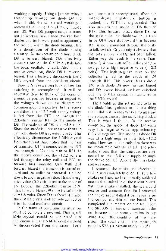
Testing. To check an SCR, connect an ohmmeter as shown in Fig.1. The
resistance between the anode and cathode should be very high regardless of the ohmmeter polarity. Then temporarily short the anode (connected to the positive ohmmeter lead) to the gate. The SCR should immediately turn on showing a low resistance on the ohmmeter, and should continue con- ducting even after the gate lead has been removed from the anode. Once the anode -cathode circuit begins conduction, the gate has no control. Now removing either of the ohmmeter leads, even for an instant, will turn off the SCR and it will return to its high resistance orginal condition.
RXISCALE
O O
O O
20 NRI Journal
www.americanradiohistory.com

NRI HONORS PROGRAM AWARDS For outstanding grades throughout their NRI courses of study, the following May and June graduates
were given Certificates of Distinction with their NRI Electronics diplomas.
WITH HIGHEST HONORS
Anthony V. Ciarlante, Alexandria VA Dale J. Solarz, Adelphi MD Rodney J. Wokojance, Vancouver WA
WITH HIGH HONORS
R. Artes, Winnipeg, MB, Canada Ronald L. Barry, Jacksonville FL Richard Borden, Enon OH James D. Cooper, Carbondale KS Lester T. Craft, Ada OK Bruce L. Cranston, Tempe AR M. Duane Cronier, Moss Paint MS Harry J. Crowley, Jr., Wilmington DE Gerald Wesley Dyer, FPO Seattle John B. Force, Bancroft MI Bernard Hetu, Beaconsfield, PQ, Canada Kenneth W. Jackson, Washington PA Lee Kerber, Warren OH Elwynn L. Ke John A La. 'J1 George O.
George111111 H. r I
q it Ir+1j Xg John
Geor John S. L . i anoverr ark James W. et J. Arlo MIowArmi Fmk* Thomas D. Newman, Waterfal Wilbur E. Olson, Jr., Raleigh NC C. S. Romaine, Richmond VA W. G. Schetrompf, Mentor OH Richard E. Sharpless, Pittsburgh PA Carey Charles Tate, Evanston IL James T. Williams, Alexandria VA Trevor Young, Sheffield MA Richard J. Zendarski, Owego NY Robert L. Zettlemoyer, Federal Way WA
WITH -IONORS
Michael D. Barkdoll, Camp Hill PA Joseph Bergeron, APO New York Frank J. Bettine, Hartshorne OK
Wadek B. Bryslawskyj, Astoria NY James Campbell, Natick MA Warren Y. H. Char, Ewa Beach HI Ernest R. Cook, Reform AL William R. Daniels, North Huntington PA
William H. Davis, Philadelphia PA
Gerald L. Derouen, Sr., New Iberia LA Benny De Santis, Ocean Springs MS
Thomas R. Dorsey, Jr., Advance NC Dominic D'urso, Niles OH Robert W. Eskew, Huntingdon TN Michael Forrester, Wabush, NF AOR IBO, Canada Donald Gaudet, Dorchester, CO PQ, Canada Allen Joseph Gibson, Sandersville GA J. Gillespie, Kekaha HI Donovald Gladney, Maywood IL Robert E. Highlands Carlisle PA
Rudolph s;.>>'' Francisco . Hunt, Yel
Blanche I. Johnson, r., B
ow Sprin ort Townsend W ssemer AL rist9vàn PA
~ e ssasVA`
Kuykendall, V/C, 11 a, Phil IhpFa P Ft'' '
m LesniBag,Gitÿ,Ml, Ira +cott Levins, FPO'1edy5 Yie riC
Z;{cine1ÌlD ar,téstft: tflír r I.èndriá VÀ" my: ee awa OK', -. -
Carlton F. Posey, Brent AL Luther E. Ratliff, Lowry AFB CO Conrad Preiner, Shoreview MN Winston J. Reese, Iowa City IA Howard L. Rinker, Afton NY Larry H. Runions, Hartsville SC Frank J. Russo, Silver Spring MD Richard L. Sadler, Lynchburg VA Robert C. Shears, Bloomington IL Robert Snellman, Howell MI Richard W. Stephens, Parkersburg WV Jim Sylvester, Springfield MO Dewey H. Taylor, Raleigh NC James A. Warner, Pennsville NJ Richard S. Wierenga II, Grand Rapids MI Leslie Wortman, Houston TX
September/October 21
www.americanradiohistory.com
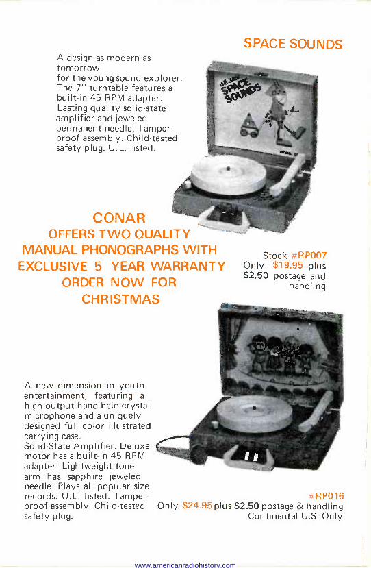
A design as modern as tomorrow for the young sound explorer. The 7" turntable features a
built-in 45 RPM adapter. Lasting quality solid-state amplifier and jeweled permanent needle. Tamper- proof assembly. Child -tested safety plug. U.L. listed.
CONAR OFFERS TWO QUALITY
MANUAL PHONOGRAPHS WITH EXCLUSIVE 5 YEAR WARRANTY
ORDER NOW FOR
CHRISTMAS
A new dimension in youth entertainment, featuring a
high output hand-held crystal microphone and a uniquely designed full color illustrated carrying case. Solid -State Amplifier. Deluxe motor has a built-in 45 RPM adapter. Lightweight tone arm has sapphire jeweled needle. Plays all popular size records. U.L. listed. Tamper- -: RP016 proof assembly. Child -tested Only S24.95 plus $2.50 postage & handling safety plug. Continental U.S. Only
SPACE SOUNDS
Stock =RP007 Only $19.95 plus $2.50 postage and
handling
www.americanradiohistory.com
I II
As this is being written (mid July), the FCC has still not released the newest Part 97 Rules and Regulations. These were supposed to be published in March (the first revised Part 97 was printed and released in March, 1976), and the word we get from the Government Printing Office is that, yes, there is a new publi- cation, and yes, it is the March, 1977 edition, but no, it is not in print yet.
I do not know the legal aspects of all this, but I wonder if we are supposed to be bound (legally) by the Rules published last March? If it came to resolving a
citation issued by the Candy Company, I'd bet against it. The "out," or dis- claimer, in the volume printed last year clearly says that the newest rules changes will be printed in the Federal Register, and if it just so happens that you (or I) don't have access to the Federal Register, that's tough.
At any rate, instead of publishing the newest rules changes in their entirety as indicated in the last Journal, we will continue our "summary" as we did last time. Hopefully, we will have the new rules in hand before the next Journal, and we will do as promised last time, and print all the significant changes verbatim from the new Part 97.
HAM NEWS
By Ted Beach K4MKX
When I was just getting into amateur radio back in the 1950's, I used to read QST with fervor, and went over every one of the various columns in the magazine. I used to be quite curious about the little cartoon figures interspersed throughout the magazine that exhorted one to "Switch to Safety." It was some time before I found out exactly what they were talking about.
In one issue, there was an article devoted to the Switch to Safety theme. The author went into great detail about the obvious need for precaution when working on transmitters which used fairly husky power supplies. This included all the standard cabinet interlock switches, grounding procedures, and everything else used when one delved into the innards of a transmitter. Toward the end of the article, there was some slight mention of safety requirements when working with receivers. However, this was a fairly short bit, and didn't stick in mind as did the gory things mentioned about the hazards of high voltages in transmitter power supplies.
Well, one of the things that I do remember that was mentioned about working with receivers is that one should have a good lightning arrestor system on
September/October 23
www.americanradiohistory.com
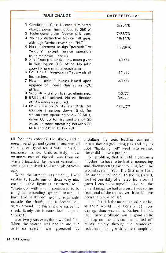
RULE CHANGE DATE EFFECTIVE
1 Conditional Class License eliminated. Novice power limit upped to 250 W.
2 Technicians given Novice privileges. 3 No new distinctive Novice call signs,
although Novices may sign "IN." 4 No requirement to sign "portable" or
"mobile" except foreign operators using reciprocal licenses.
5 First "comprehensive" cw exam given in Washington D.C. office. No solid copy for one minute requirement.
6 Court case "temporarily" suspends all license fees.
7 New "interim" licenses issued upon upgrade of license class at an FCC office.
8 Secondary station licenses eliminated. 9 97.95(a)(2) deleted. No notification
of new address required. 10 New emission purity standards. All
spurious emissions down 40 db for transmitters operating below 30 MHz, down 60 db for transmitters of 25 watts or more operating between 30 MHz and 235 MHz. (97.73)
6/25/76
7/23/76 10/1/76
11/26/76
1/1/77
1/1/77
3/1/77
3/3/77 3/9/77
4/15/77
all feedlines entering the shack, and a good overall ground system if one wanted to stay on good terms with one's fire insurance carrier. Unfortunately, these warnings sort of slipped away from me when I installed the present vertical an- tenna on the shack roof a couple of years ago.
When the antenna was erected, I was unable to locate one of those very nice coaxial cable lightning arrestors, so 1
"made do" with what I considered to be a "good grounding system" instead. I
have two, eight -foot ground rods right outside the shack, and a decent cold water ground line fairly nearby inside the shack. Surely this is more than adequate, thought 1.
For two years everything worked fine. When the station was not in use, the antenna system was grounded by
installing the coax feedline connector into a shorted grounding jack and my 23 foot "lightning rod" went into service. Never did I have a problem.
No problem, that is, until it became a "bother" to have to look after connecting and disconnecting the coax plug from the ground system. Yep. The first time I left the antenna connected to the rig (lazy!), we had one dilly of an electrical storm. I
guess I can color myself lucky that the only damage we had as a result was to the front end of the transceiver. It could have been the whole house!
I don't think the antenna took a strike, as there would have been a lot more damage than was done. Rather, I think that there probably was a good static buildup on the antenna that leaked off rather rapidly through the transceiver front end, taking with it the rf amplifier
24 NRI Journal
www.americanradiohistory.com
FET and a couple of capacitors. It could have been worse. The point is,
don't think only in terms of high voltage in a transmitter when you think of safety procedures. Remember the antennas too! Ground everything when it is not in use, and don't operate during electrical storms unless it is an absolute necessity. Then, be sure that you have good arrestors on all feedlines, and ground all those you are not using. I still don't have an arrestor for my one antenna, but you can rest assured that the antenna is always grounded now when it is not in use!
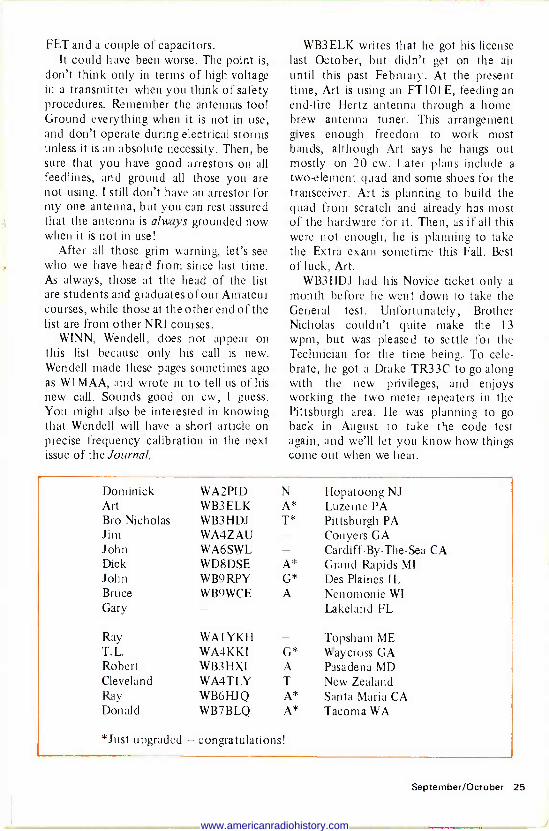
After all those grim warning, let's see who we have heard from since last time. As always, those at the head of the list are students and graduates of our Amateur courses, while those at the other end of the list are from other NRI courses.
WINN, Wendell, does not appear on this list because only his call is new. Wendell made these pages sometimes ago as W1MAA, and wrote in to tell us of his new call. Sounds good on cw, I guess. You might also be interested in knowing that Wendell will have a short article on precise frequency calibration in the next issue of the Journal.
WB3 ELK writes that he got his license last October, but didn't get on the air until this past February. At the present time, Art is using an FT101 E, feeding an end -fire Hertz antenna through a home- brew antenna tuner. This arrangement gives enough freedom to work most bands, although Art says he hangs out mostly on 20 cw. Later plans include a two -element quad and some shoes for the transceiver. Art is planning to build the quad from scratch and already has most of the hardware for it. Then, as if all this were not enough, he is planning to take the Extra exam sometime this Fall. Best of luck, Art.
WB3HDJ had his Novice ticket only a
month before he went down to take the General test. Unfortunately, Brother Nicholas couldn't quite make the 13 wpm, but was pleased to settle for the Technician for the time being. To cele- brate, he got a Drake TR33C to go along with the new privileges, and enjoys working the two meter repeaters in the Pittsburgh area. He was planning to go back in August to take the code test again, and we'll let you know how things come out when we hear.
Dominick WA2PID N Hopatoong NJ Art WB3 ELK A* Luzerne PA Bro Nicholas WB3HDJ T* Pittsburgh PA Jim WA4ZAU Conyers GA John WA6SWL Cardiff -By -The -Sea CA Dick WD8DSE A* Grand Rapids MI John WB9RPY G* Des Plaines IL Bruce WB9WCE A Nenomonie WI Gary Lakeland FL
Ray WAI YKH Topsham ME T.L. WA4KKI G* Waycross GA Robert WB3 HXI A Pasadena MD Cleveland WA4TLY T New Zealand Ray WB6HJQ A* Santa Maria CA Donald WB7BLQ A* Tacoma WA
*Just upgraded - congratulations!
September/October 25
www.americanradiohistory.com
WA4ZAU says that he wrote us last October about his new call, but some- where along the line there must have been a mishap, as I never got the information. Sorry about that, Jim. Anyway, you've finally made it, and I'm sure the other matter you wrote about has been settled also. It appeared to be a bookkeeping oversight. At the present time, Jim says that he operates mostly on 80 meters, and loves to ragchew. He even signs RCC after his call so that those who answer will know that he wants more than a brief "in and out" QSO. If anyone needs a
Georgia contact, look for WA4ZAU be- tween 3705 and 3745 from 4:30 AM to 7:00 AM EST Monday, Tuesday, or Wednesday.
WA6SWL (what a call!) got his ticket just before Christmas last year, even though he had had an interest in amateur radio for many years. John says that it took retirement to give him the time needed to really get with it and do some studying. John uses a Heath DX60 with vfo, and an HR1680 receiver with a Swan vertical. As a backup station, he has a Heath TX1 and a Lafayette receiver. John is planning to move to Florida in the near future and wants to make WAS before the move. He presently needs Georgia, South Carolina, and West Virginia to complete his list. If anyone out there could help John with a schedule, write him at 1056 Nolby Street, Cardiff -By - The -Sea, California 92007.
WD8DSE writes that he is very pleased with his NRI course. Dick says that in the group that took the Advanced test with him, several blew the code and only about half passed the written test which he breezed through, thanks to his training. Many thanks, Dick - we are all very happy for you and wish you the best of luck when you go for the Extra license!
WB9RPY tells us that he was issued one of the first Interim General tickets in his area, and that it was five weeks to the
day that he received his "permanent" ticket. Although still studying the Basic Course texts, John is already on the air with an FT101 E into a HyGain 18AVT vertical. He also bangs out a good signal on two meters with an Icom IC22s and Ranger antenna. Sounds like a real neat setup, John, and best of luck with your studies - don't stop now just because you have your license!
We had a nice note from one other student in the Amateur course, but Gary Parker hadn't yet gotten his ticket. He writes that he was planning to take the code test very soon, so perhaps he has his license by now. Gary was doing a bit of complaining about the fact that some of the regulations covered in the course were a bit outdated, as we mentioned in this column last time. We do try to keep things as up to date as we can, Gary, but it is virtually impossible, as you can imagine (with people enrolling daily), to know just who has gotten what material. So anyway, keep your eye on the most recent rules as carried here in the Journal, and you should stay pretty well on top of the rules.
WAl YKH writes that he enjoys reading the Ham News in the Journal up there in Maine. Thanks, Ray. At the present, he is mostly on two meters since his job as Electronics Branch Chief in the Navy keeps him busy most of the time. Ray is a Chief Petty Officer in the Patrol Squadron and that sounds mighty impres- sive to me.
WB3HXI says that he is an "upgrade" from CB. I hadn't heard that one before, but it sounds pretty good. Bob says the code was the only thing he stumbled on, otherwise he would have had a General call instead of Technician right off the bat. As it is, he went back three weeks later and sat for the General and Advanced and passed both! Fine business, Bob. He is using the Heath SB101 and wonders just how much power one really needs to communicate reliably. Well, I
26 NRI Journal
www.americanradiohistory.com
don't know that there is any simple answer to that question, but short of getting clobbered by the big guns running the kilowatt -plus rigs, 180 to 200 watts PEP should get through to most places at most times, providing one has a good antenna system. Just remember that a 3
db change in power gives about one S
unit difference at the receiving end, so going from 100 watts to a kilowatt (+10 db) would make a difference of perhaps three S units at the other end. Under most circumstances, the results do not justify the added problems of the linear. But, every person to his own poison I
always say. WA4TLY got his ticket back in June,
and is operating as ZL2THN from Wellington, New Zealand at the present time. Cleveland says he is mostly on two meters. However, he hopes to upgrade real soon although it is somewhat of a prob- lem because of the distance to the nearest FCC office. Hang in there, Cleveland, I
understand that under some circum- stances the FCC will still issue Condi- tional licenses. If you're on an extended tour overseas, I would certainly write the FCC to find out if it would be possible to take the test with a volunteer examiner
(assuming you can find one in New Zealand!).
WB6HJQ is taking our Communica- tions Course and asked a few questions about the two meter transceiver he will
be building as part of the course. Well,
Ray, I may be prejudiced, but I think it's a pretty darn good rig! It has a minimum power output of 20 watts (most units will
make 25 watts). There is a low power position which gives between 1 and 2
watts output and it will cover any 2 MHz segment of the two meter band in 5 kHz steps. There are three transmit modes: simplex, repeater -high, and repeater -low. In addition, all major circuit boards plug in for easy adjustment and repair and the circuits are easy to adjust using simple equipment. The seven -segment display shows up in all lighting situations. Also, the experiments prepare one for working with any type of vhf communications equipment. All in all, the rig is a very good one which will serve everyone quite well, both as a training medium and as a
useful, working, two meter station (mobile or base, with the ac supply).
Well, we are about out of space again, so until next time, very 73. Ted - K4MKX
Give [kart Fund Ill MLA 17 lC.d.l CdÍl F1JJVl.Ic1.IVil
dcpb APPRENTICE TECHNICIAN NEEDED IMMEDIATELY: NRI Graduate or advanced student preferred. For a personal interview, call 271-6580 between 8:30 a.m. and 5 p.m., Monday through Saturday. Ernie's Radio -Television Service, 809 W. St. Bernard Highway, Chalmette, Louisiana 70043.
REPAIR SHOP SPACE NEEDED: An NRI graduate, with 10 years of television servicing experience, desires busy appliance store in which to locate independent TV/Radio repair shop. Contact Thomas J. Bush, CET, 8520 Lake Atkenson Drive, Tallahassee, Florida 32304. Telephone 1904) 575-4486.
September/October 27
www.americanradiohistory.com
DIRECTORY OF ALUMNI CHAPTERS
DETROIT CHAPTER meets at 8 p.m. on the second Friday of each month at St. Andrews Hall, 431 E. Congress St., Detroit. Chairman: James Kellay, 1140 Livernois, Detroit, Michigan. 841-4972. FLINT/SAGINAW VALLEY CHAPTER meets 7:30 p.m., the second Wednesday of each month, at Andy's Radio and TV Shop, G-5507 S.
Saginaw Rd., Flint, Michigan. Chairman: Dale Keys. 639-6688. Chapter phone is 694-6773. Visitors please call to verify date. NEW YORK CITY CHAPTER meets at 8:30 p.m., the first Thursday of each month, at 1669 45th St., Brooklyn, New York. Chairman: Sam
Antman, 1669 45th St., Brooklyn, New York. NORTH JERSEY CHAPTER meets at 8 p.m. on the second Friday of each month at the Players Club, located on Washington Square in Kearny, New Jersey. Chairman: Al Mould. 991-9299 or 384-8112. PHILADELPHIA -CAMDEN CHAPTER meets on the fourth Monday of each month at 8 p.m. at the home of Chairman Boyd A. Bingaman, 426 Crotzer Ave., Folcroft, Pennsylvania. LU3-7165. PITTSBURGH CHAPTER meets at 8 p.m. on the first Thursday of each month in the basement of the U.P. Church of Verona, Pa.,
corner of South Ave. and Second St. Chairman: James Wheeler. SAN ANTONIO (ALAMO) CHAPTER meets at 7 p.m., fourth Thursday of each month, at the Alamo Heights Christian Church Scout House, 350 Primrose St., 6500 block of N. New Braunfels St. (three blocks north of Austin Hwy.), San Antonio, Texas. Chairman: Robert Bonge, 222 Amador Lane, San Antonio, Texas. All San Antonio area NRI students are always welcome. A free annual chapter membership will be given to all NRI graduates attending within three months of their graduation. SOUTHEASTERN MASSACHUSETTS CHAP- TER meets at 8 p.m. on the last Wednesday of each month at the home of Chairman Daniel DeJesus, 12 Brookview St., Fairhaven, Massa- chusetts 02719. SPRINGFIELD, MASSACHUSETTS CHAPTER meets at 7:30 p.m. on the second Saturday of each month at the shop of Chairman Norman Charest, 74 Redfern Dr., Springfield, Massachu- setts 01109. (413) 734-2609. TORONTO CHAPTER meets at McGraw-Hill CEC, 330 Progress Ave., Scarborough, Ontario, Canada. Chairman: Branko Lebar. For informa- tion call Stewart J. Kenmuir, (416) 293-1011.
Fouteen members attended the May
14 meeting. With 14 paid up members, the treasurer reported that the Chapter had $192.75 in the treasury.
Outgoing Chairman Preston Atwood was congratulated by the Chapter for the fine job he did as chairman for the last two years. Chairman Atwood has often helped the Chapter with new ideas on solid-state circuitry and with solutions to many problems he has encountered in his service work.
That evening, he told the Chapter of a
visit he made to repair a 25 inch Zenith TV which had vertical roll as well as a
curtain effect two inches wide on the bottom of the screen. Moving a 0.01 pf ceramic capacitor solved that problem, although to this day, he still wonders why. The color set has been running perfectly ever since. The 0.01 pf capacitor was in
the grid circuit of the vertical oscillator. Chairman Atwood complimented the
members for their attentiveness, and said he hoped they would feel the same respect for the newly elected officers. Norman Charest will take over the duties of
28 NRI Journal
www.americanradiohistory.com
NRIAA OFFICERS J.B. Straughn President Eldred M. Breese Vice President Branko Lebar Vice President Joseph A. Crusco Vice President Les Lederna Vice President Tom Nolan Executive Secretary
Allumnf,," \\
ewe,
chairman beginning with the September meeting.
Also at this meeting, two new members talked briefly about their appreciation of receiving the NRJ Journal. They find it interesting, informative, and friendly.
George Lewonchuk brought in an NRI voltmeter with a problem in reading the voltage on the 300 volt scale. He was advised to bring a schematic to the September meeting where members will try to solve the problem.
The meeting adjourned at 9:30 p.m. with coffee and doughnuts served by Norman Charest.
The annual picnic for members and their spouses was held June 25 at the home of Mr. and Mrs. John Park of Ware, Massachusetts.
NORTH JERSEY CHAPTER ENTERTAINS EXECUTIVE
SECRETARY
The North Jersey Chapter heard Tom Nolan, Executive Secretary of the NRIAA, speak about CB's at their May 22 meeting. Refreshments were served after a discussion between Tom and the members.
PITTSBURGH CHAPTER HEARS CB LECTURE
Tom Nolan, Executive Secretary of the NRIAA, lectured the Pittsburgh Chapter at their meeting June 2. His topic was "CB Installation and Servicing."
After the meeting, Tom held a question and answer session. A great deal of infor- mation was brought forward.
DIAGNOSTIC MEETINGS CONTINUE AT
DETROIT CHAPTER
At the April meeting, Tom Tishler gave a talk and demonstration of a
troublesome transistor circuit. The col- lector current could not be controlled with different bias voltages low enough to cause saturation. The problem was traced to a defective transistor.
In addition, Ed Quinn checked through the circuits of a CONAR tvom which had stopped operating that a visitor had brought in. With helpful comments from the members, he discovered that it had a
bad FET. At the May meeting, The Chapter had
a request from a gentleman looking for a
September/October 29
www.americanradiohistory.com
6 volt vibrator for his old Ford (Philco) car radio. F. Earl Oliver volunteered to supply him with one. No problem!
Another visitor brought in a GE porta- ble color TV that reproduced good sound, but had no raster. There was no output of any kind beyond the horizontal oscillator stage. It turned out to have a burned out thermistor due to an overload in the hori- zontal output section.
All members have been participating in diagnostic procedures with various pieces of equipment. They also learn to under- stand the theories behind the procedures at the same time.
At the June meeting, John Nagy spoke about the Consumer Electronic and the Sound and Light Shows he attended in Chicago. He explained many of the uses of electronic blocks in practical applica- tions, such as building circuits, reading test panels, and experimentation. He then dis- cussed home computers and their potential for the service technician in the future. Folders on these devices were distributed.
Tom Tishler gave a talk board discus- sion of a problem circuit with a bipolar power transistor involved. Jim Kelley fol- lowed with a practical demonstration of the circuit using an operational transistor circuit board he built and a bench -type vtvm so all could see the output readings.
Don Hughes pinpointed leakage in the original transistor of the problem circuit as the problem in his new transistor tester. It was solved with a new transistor.
Asa Belton and Gilbert Sager brought in an old radio to be used for pratical training experiments. The one that Gil brought in was a 1946 vintage RCA table model which suffered from constant hum. The trouble was quickly traced to a defective combination electrolytic filter capacitor. Separate capacitors were in- stalled because the original was not available.
The annual election of officers and committee members was held at the meeting. Those elected were: James
Kelley, chairman; Ray Berus, Vice -Chair- man; Tom Tishler, Secretary; F. Earl Oliver, Treasurer; Prince Bray, Librarian; and Bruce Rittenhouse, Sergeant -at -Arms.
Members of the finance committee will include John Nagy and Leo Blevins. A new research committee was formed to research and present information on new developments in the field of electronics. Ed Quinn and John Nagy will serve on this committee.
All those elected will be installed and assume their duties in September. There are no meetings during July and August.
GOOD ATTENDANCE AT FLINT/ SAGINAW VALLEY CHAPTER
At the May 11 meeting, Dale Keys brought in two General Electric color television sets for experimental service work. After the experiments, Fred Malik, Jerry Lev, Dale Keys, Chester Mazur, and Jack Heilborn disassembled the sets. They used the cabinets for phonograph records and salvaged some of the spare parts.
The Chapter is opening up a new sales and service outlet for CB radios and security systems. This will be at the branch office at G5513 S. Saginaw, next door to the Chapter headquarters. The call letters for the CB station are KDS6511.
At the June 8 meeting, the Chapter took two television sets and made one good set from the parts.
At the June 22 meeting, Jerry Lev brought in a black -and -white television set with no high voltage. After making a
few checks, he found that the yoke was shorted. However, when a substitute yoke was used, the set played but it also had a vertical problem. After a few more checks, he found that the retrace con- denser was bad. When it was replaced, the vertical was okay.
Andy Jobbagy worked on a Mont- gomery Ward color set which had a high - voltage arc. After the focus voltage module was replaced, the set performed perfectly.
30 NRI Journal
www.americanradiohistory.com
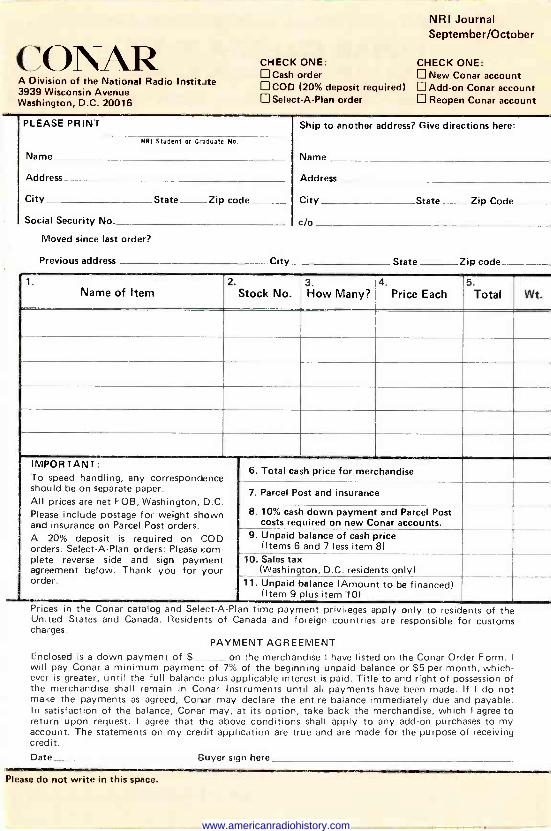
NRI Journal September/October
C \ AR A Division of the National Radio Institute 3939 Wisconsin Avenue Washington, D.C. 20016
CHECK ONE: CHECK ONE: Cash order New Conar account COD (20% deposit required) Add-on Conar account Select -A -Plan order Reopen Conar account
PLEASE PRINT Ship to another address? Give directions here:
Name Name
NM Student or Graduate No.
Address Address
City State Zip code City State Zip Code
Social Security No. c/o
Moved since last order?
Previous address City State Zip code
1. Name of Item
2. Stock No.
3. How Many?
4. Price Each
5. Total Wt.
IMPORTANT: To speed handling, any correspondence should be on separate paper. All prices are net FOB, Washington D C
Please include postage for weight shown and insurance on Parcel Post orders. A 20% deposit is required on COD orders. Select -A -Plan orders: Please com- plete reverse side and sign payment agreement below. Thank you for your order.
6. Total cash price for merchandise
7. Parcel Post and insurance
8. 10% cash down payment and Parcel Post costs required on new Conar accounts.
9. Unpaid balance of cash price (Items 6 and 7 less item 8)
10. Sales tax (Washington, D.C. residents only)
11. Unpaid balance (Amount to be financed) (Item 9 plus item 10)
Prices in the Conar catalog and Select -A -Plan time payment privileges apply only to residents of the United States and Canada. Residents of Canada and foreign countries are responsible for customs charges.
PAYMENT AGREEMENT Enclosed is a down payment of $ on the merchandise I have listed on the Conar Order Form. I
will pay Conar a minimum payment of 7% of the beginning unpaid balance or $5 per month, which- ever is greater, until the full balance plus applicable interest is paid. Title to and right of possession of the merchandise shall remain in Conar Instruments until all payments have been made. If I do not make the payments as agreed, Conar may declare the entire balance immediately due and payable. In satisfaction of the balance, Conar may, at its option, take back the merchandise, which I agree to return upon request. I agree that the above conditions shall apply to any add-on purchases to my account. The statements on my credit application are true and are made for the purpose of receiving credit. Date Buyer sign here
Please do not write in this space.
www.americanradiohistory.com
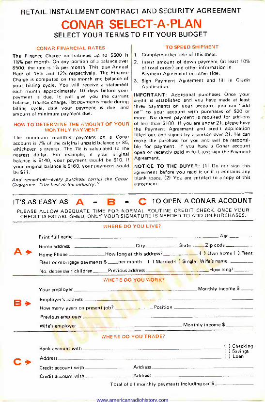
RETAIL INSTALLMENT CONTRACT AND SECURITY AGREEMENT
CONAR SELECT -A -PLAN SELECT YOUR TERMS TO FIT YOUR BUDGET
CONAR FINANCIAL RATES
The Finance Charge on balances up to $500 is
1'/z% per month. On any portion of a balance over
$500, the rate is 1% per month. This is an Annual Rate of 18% and 12% respectively. The Finance Charge is computed on the month end balance of your billing cycle. You will receive a statement each month approximately 10 days before your payment is due. It will give you the current balance, finance charge, list payments made during billing cycle, date your payment is due, and
amount of minimum payment due.
HOW TO DETERMINE THE AMOUNT OF YOUR MONTHLY PAYMENT
The minimum monthly payment on a Conar account is 7% of the original unpaid balance or $5, whichever is greater. The 7% is calculated to the nearest dollar. For example, if your original balance is $140, your payment would be $10. If your original balance is $160, your payment would be $11.
And remember-every purchase carries the Conar Guarantee-'the best in the industry."
TO SPEED SHIPMENT
1. Complete other side of this sheet.
2. Insert amount of down payment (at least 10%
of total order) and other information in
Payment Agreement on other side.
3. Sign Payment Agreement and fill in Credit Application.
IMPORTANT: Additional purchases-Once your credit is established and you have made at least
three payments on your account, you can "add on" to your account with purchases of $20 or more. No down payment is required for add-ons of less than $100. If you are under 21, please have
the Payment Agreement and credit application filled out and signed by a person over 21. He can
make the purchase for you and will be responsi- ble for payment. If you have a Conar account open or recently paid in full, just sign the Payment Agreement.
NOTICE TO THE BUYER: (1) Do not sign this agreement before you read it or if it contains any blank space. (2) You are entitled to a copy of this agreement.
IT'S AS EASY AS A - B - C TO OPEN A CONAR ACCOUNT
PLEASE ALLOW ADEQUATE TIME FOR NORMAL ROUTINE CREDIT CHECK. ONCE YOUR CREDIT IS ESTABLISHED, ONLY YOUR SIGNATURE IS NEEDED TO ADD ON PURCHASES.
A*
WHERE DO YOU LIVE?
Print full name Age
Home address City State - Zip code
Home Phone How long at this address? 1 I Own home ( ) Rent
Rent or mortgage payments $ per month ( ) Married ( I Single Wife's name
No. dependent children Previous address How long?
B*
WHERE DO YOU WORK?
Your employer Monthly income $
Employer's address
How many years on present job? Position
Previous employer
Wife's employer Monthly income $
C WHERE DO YOU TRADE?
Bank account with
Address
Credit account with Address
Credit account with Address
Total of all monthly payments including car $
( ) Checking ( ) Savings ( ) Loan
www.americanradiohistory.com
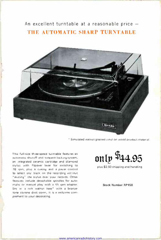
s
>
An excellent turntable at a reasonable price - THE AUTOMATIC SHARP TURN'T'ABLE
Simulated walnut grained vinyl on wood product material.
This full-size three -speed turntable features an
automatic shutoff and tonearm locking system; an integrated ceramic cartridge and diamond stylus with flipover lever for switching to 78 rpm; plus a cueing and a pause control to select any track on the recording without "skating" the stylus over your records. Other features include detachable spindles for auto- matic or manual play with a 45 rpm adapter. Set in a rich walnut base" with a bronze -
tone styrene dust cover, it is a welcome com- plement to your decorating.
onlp X44.95 plus $2.50 shipping and handling
Stock Number RP150
www.americanradiohistory.com
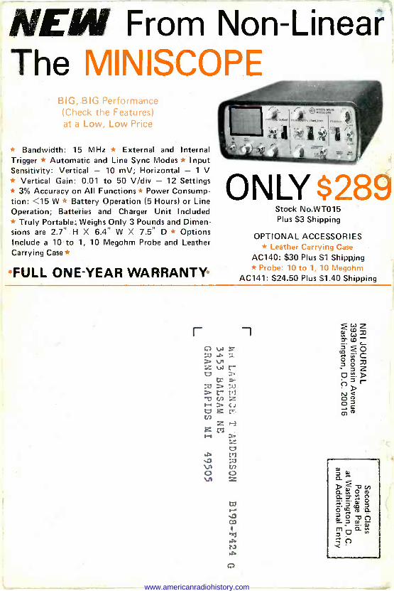
NEW From Non -Linear The MINISCOPE
BIG, BIG Performance (Check the Features) at a Low, Low Price
* Bandwidth: 15 MHz * External and Internal Trigger * Automatic and Line Sync Modes * Input Sensitivity: Vertical - 10 mV; Horizontal - 1 V * Vertical Gain: 0.01 to 50 V/div - 12 Settings * 3% Accuracy on All Functions * Power Consump- tion: <15 W * Battery Operation (5 Hours) or Line Operation; Batteries and Charger Unit Included * Truly Portable: Weighs Only 3 Pounds and Dimen- sions are 2.7" H X 6.4" W X 7.5" D * Options Include a 10 to 1, 10 Megohm Probe and Leather Carrying Case
FULL ONE-YEAR WARRANTY
r
ONLY S289 Stock No.WT015 Plus $3 Shipping
OPTIONAL ACCESSORIES * Leather Carrying Case
AC140: $30 Plus $1 Shipping * Probe: 10 to 1, 10 Megohm
AC141: $24.50 Plus $1.40 Shipping
O
www.americanradiohistory.com