Embed Size (px)
Citation preview
Part Number 752485Bulletin 464GEffective 8/28/2002
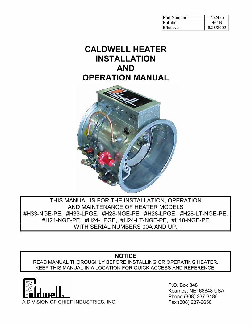
CALDWELL HEATER INSTALLATION
AND OPERATION MANUAL
THIS MANUAL IS FOR THE INSTALLATION, OPERATION
AND MAINTENANCE OF HEATER MODELS #H33-NGE-PE, #H33-LPGE, #H28-NGE-PE, #H28-LPGE, #H28-LT-NGE-PE,
#H24-NGE-PE, #H24-LPGE, #H24-LT-NGE-PE, #H18-NGE-PE WITH SERIAL NUMBERS 00A AND UP.
NOTICE READ MANUAL THOROUGHLY BEFORE INSTALLING OR OPERATING HEATER. KEEP THIS MANUAL IN A LOCATION FOR QUICK ACCESS AND REFERENCE.
A DIVISION OF CHIEF INDUSTRIES, INC
P.O. Box 848 Kearney, NE 68848 USA Phone (308) 237-3186 Fax (308) 237-2650
Part Number 752485Bulletin 464GEffective 8/28/2002
Page 2 of 41
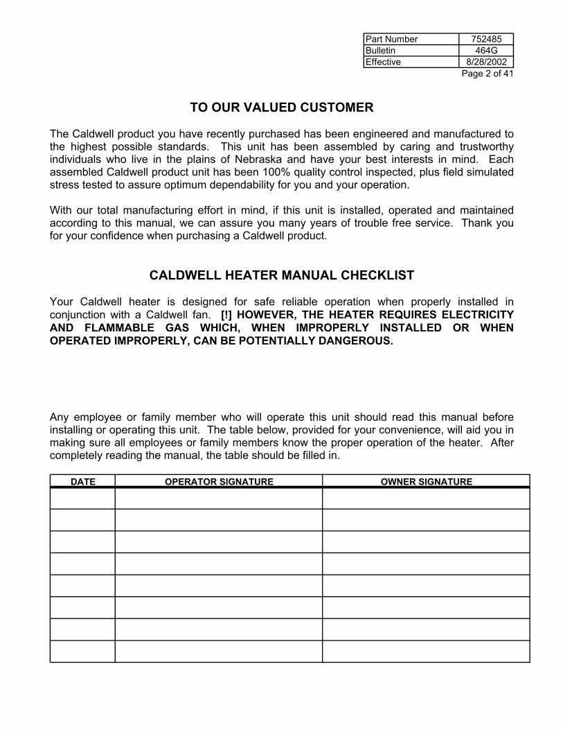
TO OUR VALUED CUSTOMER The Caldwell product you have recently purchased has been engineered and manufactured to the highest possible standards. This unit has been assembled by caring and trustworthy individuals who live in the plains of Nebraska and have your best interests in mind. Each assembled Caldwell product unit has been 100% quality control inspected, plus field simulated stress tested to assure optimum dependability for you and your operation. With our total manufacturing effort in mind, if this unit is installed, operated and maintained according to this manual, we can assure you many years of trouble free service. Thank you for your confidence when purchasing a Caldwell product.
CALDWELL HEATER MANUAL CHECKLIST
Your Caldwell heater is designed for safe reliable operation when properly installed in conjunction with a Caldwell fan. [!] HOWEVER, THE HEATER REQUIRES ELECTRICITY AND FLAMMABLE GAS WHICH, WHEN IMPROPERLY INSTALLED OR WHEN OPERATED IMPROPERLY, CAN BE POTENTIALLY DANGEROUS. Any employee or family member who will operate this unit should read this manual before installing or operating this unit. The table below, provided for your convenience, will aid you in making sure all employees or family members know the proper operation of the heater. After completely reading the manual, the table should be filled in.
DATE OPERATOR SIGNATURE OWNER SIGNATURE
Part Number 752485Bulletin 464GEffective 8/28/2002 Page 3 of 41
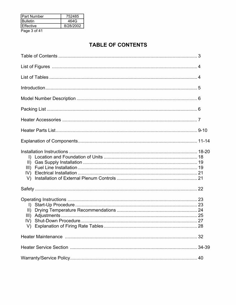
TABLE OF CONTENTS
Table of Contents ........................................................................................................... 3 List of Figures ................................................................................................................ 4 List of Tables .................................................................................................................. 4 Introduction..................................................................................................................... 5 Model Number Description ............................................................................................. 6 Packing List .................................................................................................................... 6 Heater Accessories ........................................................................................................ 7 Heater Parts List............................................................................................................. 9-10 Explanation of Components............................................................................................ 11-14 Installation Instructions ................................................................................................... 18-20 I) Location and Foundation of Units ........................................................................ 18 II) Gas Supply Installation ........................................................................................ 19 III) Fuel Line Installation ............................................................................................ 19 IV) Electrical Installation ............................................................................................ 21 V) Installation of External Plenum Controls .............................................................. 21 Safety ............................................................................................................................. 22 Operating Instructions .................................................................................................... 23 I) Start-Up Procedure .............................................................................................. 23 II) Drying Temperature Recommendations .............................................................. 24 III) Adjustments ......................................................................................................... 25 IV) Shut-Down Procedure.......................................................................................... 27 V) Explanation of Firing Rate Tables ........................................................................ 28 Heater Maintenance ...................................................................................................... 32 Heater Service Section .................................................................................................. 34-39 Warranty/Service Policy.................................................................................................. 40
Part Number 752485Bulletin 464GEffective 8/28/2002
Page 4 of 41
LIST OF FIGURES
Page Figure 1. Typical Serial Number Plate ............................................................................5 Figure 2. Control Enclosure Components.......................................................................7 Figure 3. Heater Components ........................................................................................8 Figure 4. Typical Installation .........................................................................................15 Figure 5. Typical Installation of Two Drying Units and Optional Plenum Controls ........16 Figure 6. Fan and Heater Mounting Pads.....................................................................17 Figure 7. Propane Tank Plumbing Installation ..............................................................19 Figure 8. Heater Electrical Supply Connection .............................................................21 Figure 9. Bin Vent Warning Decal ................................................................................22 Figure 10. Flame Probe Adjustment ...............................................................................25 Figure 11. Heater Wiring Diagram ..................................................................................33
LIST OF TABLES Table 1. Packing List .....................................................................................................6 Table 2. Replacement Parts List (For Common Parts)..................................................9 Table 3. Replacement Parts List (For Specific Models)...............................................10 Table 4. Drying Temperature Recommendation..........................................................24 Table 5. Firing Rate for H18-Propane with 3HP Axial..................................................29 Table 6. Firing Rate for H18-Natural Gas with 3HP Axial ............................................29 Table 7. Firing Rate for H24-Propane with 10HP Axial................................................30 Table 8. Firing Rate for H24-Natural Gas with 10HP Axial ..........................................30 Table 9. Firing Rate for H28-Propane with 12.5HP Axial.............................................31 Table 10. Firing Rate for H28-Natural Gas with 12.5HP Axial .......................................31
Part Number 752485Bulletin 464GEffective 8/28/2002 Page 5 of 41
CALDWELL HEATER INSTALLATION AND OPERATION MANUAL
THIS MANUAL IS FOR THE INSTALLATION, OPERATION AND MAINTENANCE OF H33, H28, H24, AND H18 SERIES HEATERS WITH SERIAL NUMBER OF 00A AND UP. READ MANUAL THOROUGHLY BEFORE INSTALLING OR OPERATING YOUR CALDWELL HEATER. KEEP THIS MANUAL IN A LOCATION FOR QUICK ACCESS AND REFERENCE. SPECIAL SERVICE NOTICE If you are unable to remedy any service problem after thoroughly studying this manual, contact the dealer from whom you purchased the unit. YOUR DEALER IS YOUR FIRST LINE OF SERVICE. GIVE HIM THE INFORMATION REQUESTED BELOW AND EXPLAIN YOUR PROBLEM. If he is unable to correct the problem, refer to the factory. When calling the factory for service, ask for the Customer Service Department. Give the information requested below and explain your problem. If adequate information relating to the problem is given, the Service Department should be able to pinpoint the problem and suggest an immediate solution. CHIEF INDUSTRIES, INC., AGRI/INDUSTRIAL DIVISION SERVICE POLICY IS INCLUDED AT THE END OF THE MANUAL.
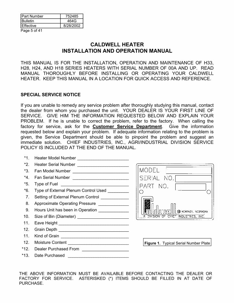
*1. Heater Model Number ______________________ *2. Heater Serial Number ______________________ *3. Fan Model Number ________________________ *4. Fan Serial Number ________________________ *5. Type of Fuel _____________________________ *6. Type of External Plenum Control Used _________ 7. Setting of External Plenum Control ____________ 8. Approximate Operating Pressure _____________ 9. Hours Unit has been in Operation _____________ 10. Size of Bin (Diameter) ______________________ 11. Eave Height ______________________________ 12. Grain Depth ______________________________ 11. Kind of Grain _____________________________ 12. Moisture Content __________________________ *12. Dealer Purchased From ____________________ *13. Date Purchased __________________________
THE ABOVE INFORMATION MUST BE AVAILABLE BEFORE CONTACTING THE DEALER OR FACTORY FOR SERVICE. ASTERISKED (*) ITEMS SHOULD BE FILLED IN AT DATE OF PURCHASE.
Figure 1. Typical Serial Number Plate
Part Number 752485Bulletin 464GEffective 8/28/2002
Page 6 of 41
MODEL NUMBER DESCRIPTION
The heater model nomenclature distinguishes the application of the heater. The information includes a designation of the applicable fan and type of fuel to be utilized either natural gas, vapor propane, or liquid propane. The model number is stamped on the serial number plate and the definition of the model number nomenclature is as follows: Example: H 28 - LT - NGE-PE - M (a) (b) (c) (d) (e) (a) H = Heater Unit
(b) 28 = Housing Diameter
(c) LT = Low Temperature
(d) NGE = Type of Fuel to be Utilized Where NGE-PE Natural Gas or Propane Vapor Fuel (Electric) LPGE Liquid Propane Gas Fuel (Electric)
(e) M = with Modulating Valve
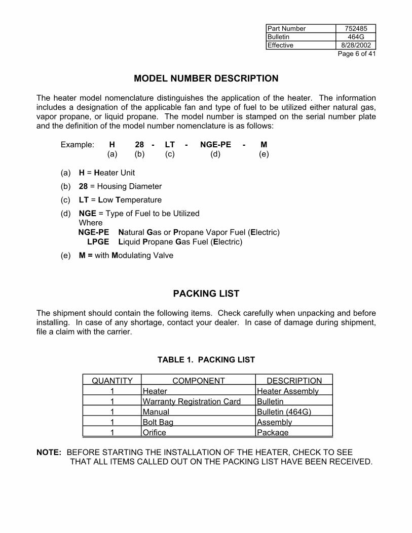
PACKING LIST
The shipment should contain the following items. Check carefully when unpacking and before installing. In case of any shortage, contact your dealer. In case of damage during shipment, file a claim with the carrier.
TABLE 1. PACKING LIST
NOTE: BEFORE STARTING THE INSTALLATION OF THE HEATER, CHECK TO SEE THAT ALL ITEMS CALLED OUT ON THE PACKING LIST HAVE BEEN RECEIVED.
QUANTITY COMPONENT DESCRIPTION1 Heater Heater Assembly1 Warranty Registration Card Bulletin1 Manual Bulletin (464G)1 Bolt Bag Assembly1 Orifice Package
Part Number 752485Bulletin 464GEffective 8/28/2002 Page 7 of 41
HEATER ACCESSORIES
1. A Humidistat, Thermostat, or Thermostat-Humidistat Control is not included with the standard heater. They are to be ordered separately. A dual Humidistat-Thermostat Kit can be ordered so that one control assembly can be used when two heater units are used on the same bin.
2. Caldwell requires using a fuel line strainer in the fuel line just before the fuel enters the
heater plumbing. A line strainer is provided on LPGE units, but not on NGE-PE units. A line strainer can be obtained from Caldwell, or your gas company.
CAUTION: YOUR WARRANTY COULD BE JEOPARDIZED IF THE HEATER SHOULD
MALFUNCTION DUE TO FOREIGN MATERIAL FOUND IN THE HEATER PLUMBING AND THE FUEL SUPPLY LINE DOES NOT HAVE A LINE STRAINER.
3. A Caldwell Vaporizer can be ordered and field installed on H24-NGE-PE and H28-NGE-PE
units, to assure a supply of propane vapor to the heater when conditions are such that the supply tank does not supply a sufficient volume of vapor to the unit. The vaporizer is a standard part on H24-LPGE and H28-LPGE units.
4. When installing the heater on a centrifugal fan, a centrifugal cord/airswitch kit for an
upstream heater must be ordered (part #195864). 5. When wiring a heater to a 460 or 575 volt fan, a Step Down Transformer must be used to
develop 115 volt, single phase, 60 cycle power (part #717033).
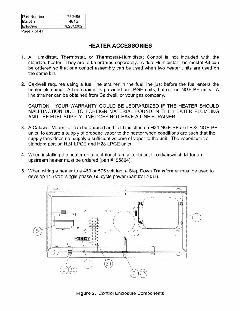
Figure 2. Control Enclosure Components
Part Number 752485Bulletin 464GEffective 8/28/2002
Page 8 of 41
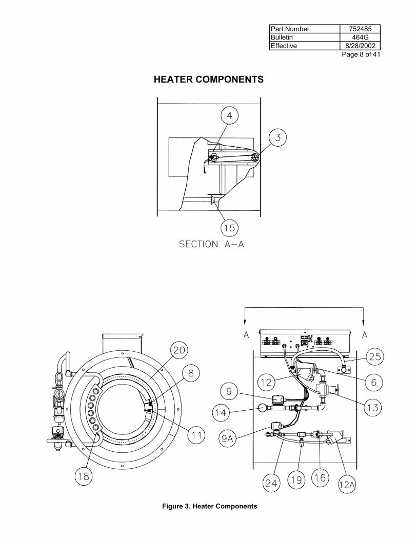
HEATER COMPONENTS
Figure 3. Heater Components
Part Number 752485Bulletin 464GEffective 8/28/2002 Page 9 of 41
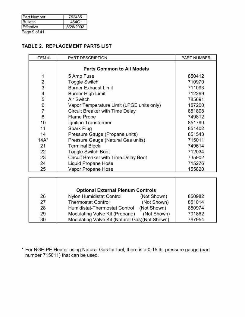
TABLE 2. REPLACEMENT PARTS LIST
ITEM # PART DESCRIPTION PART NUMBER
Parts Common to All Models1 5 Amp Fuse 8504122 Toggle Switch 7109703 Burner Exhaust Limit 7110934 Burner High Limit 7122995 Air Switch 7856916 Vapor Temperature Limit (LPGE units only) 1572007 Circuit Breaker with Time Delay 8518088 Flame Probe 749812
10 Ignition Transformer 85179011 Spark Plug 85140214 Pressure Gauge (Propane units) 851543
14A* Pressure Gauge (Natural Gas units) 71501121 Terminal Block 74961422 Toggle Switch Boot 71203423 Circuit Breaker with Time Delay Boot 73590224 Liquid Propane Hose 71527625 Vapor Propane Hose 155820
Optional External Plenum Controls26 Nylon Humidistat Control (Not Shown) 85098227 Thermostat Control (Not Shown) 85101428 Humidistat-Thermostat Control (Not Shown) 85097429 Modulating Valve Kit (Propane) (Not Shown) 70186230 Modulating Valve Kit (Natural Gas)(Not Shown) 767954
* For NGE-PE Heater using Natural Gas for fuel, there is a 0-15 lb. pressure gauge (part number 715011) that can be used.
Part Number 752485Bulletin 464GEffective 8/28/2002
Page 10 of 41
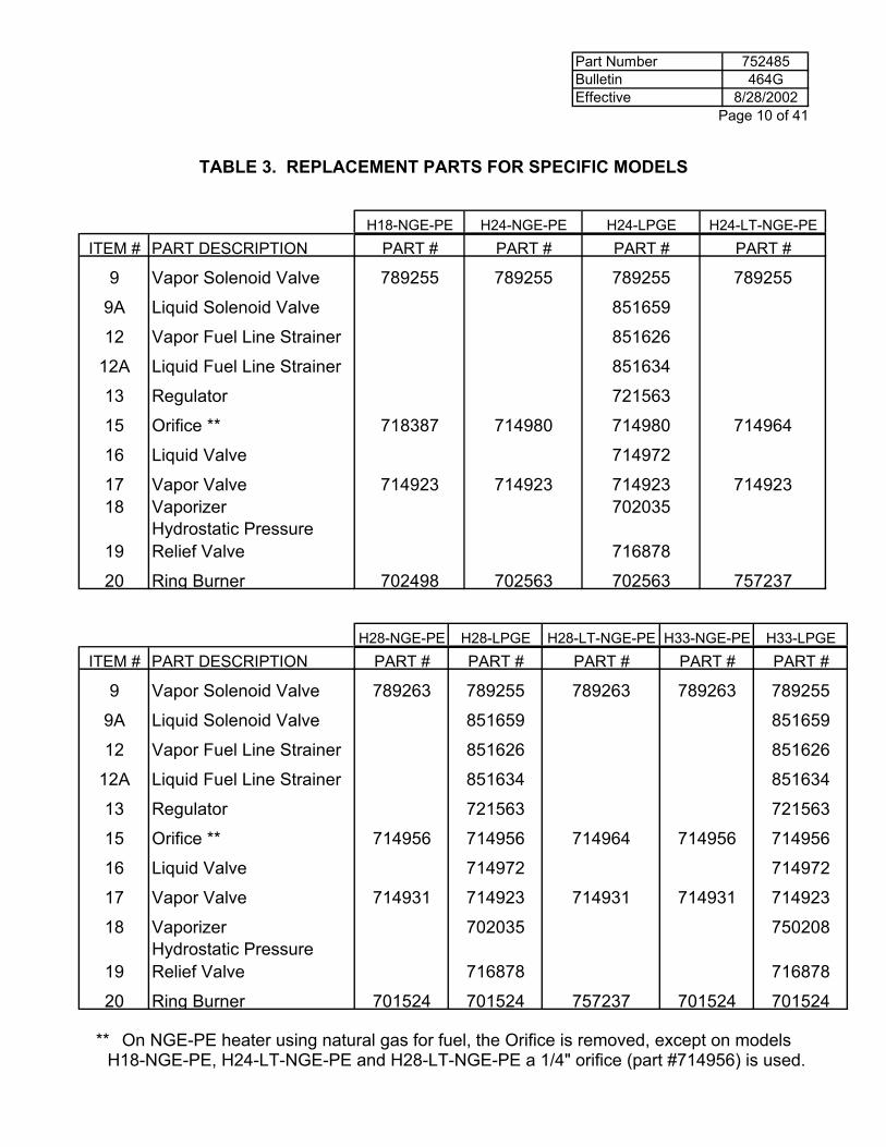
TABLE 3. REPLACEMENT PARTS FOR SPECIFIC MODELS
H18-NGE-PE H24-NGE-PE H24-LPGE H24-LT-NGE-PE
ITEM # PART DESCRIPTION PART # PART # PART # PART #
9 Vapor Solenoid Valve 789255 789255 789255 789255
9A Liquid Solenoid Valve 851659
12 Vapor Fuel Line Strainer 851626
12A Liquid Fuel Line Strainer 851634
13 Regulator 721563
15 Orifice ** 718387 714980 714980 714964
16 Liquid Valve 714972
17 Vapor Valve 714923 714923 714923 71492318 Vaporizer 702035
19Hydrostatic Pressure Relief Valve 716878
20 Ring Burner 702498 702563 702563 757237
H28-NGE-PE H28-LPGE H28-LT-NGE-PE H33-NGE-PE H33-LPGE
ITEM # PART DESCRIPTION PART # PART # PART # PART # PART #
9 Vapor Solenoid Valve 789263 789255 789263 789263 789255
9A Liquid Solenoid Valve 851659 851659
12 Vapor Fuel Line Strainer 851626 851626
12A Liquid Fuel Line Strainer 851634 851634
13 Regulator 721563 721563
15 Orifice ** 714956 714956 714964 714956 714956
16 Liquid Valve 714972 714972
17 Vapor Valve 714931 714923 714931 714931 714923
18 Vaporizer 702035 750208
19Hydrostatic Pressure Relief Valve 716878 716878
20 Ring Burner 701524 701524 757237 701524 701524
** On NGE-PE heater using natural gas for fuel, the Orifice is removed, except on models H18-NGE-PE, H24-LT-NGE-PE and H28-LT-NGE-PE a 1/4" orifice (part #714956) is used.
Part Number 752485Bulletin 464GEffective 8/28/2002 Page 11 of 41
EXPLANATION OF COMPONENTS
An understanding of the heater operation can be obtained by learning the function of each heater component. Refer to Figures 2 and 3 on pages 7 and 8, and Tables 2 and 3 on pages 9 and 10 while studying the following section. The figures illustrate each component. Electrical 1. 5 Amp Fuse #850412 The fuse protects the Heater Control Circuit from excessive current draw.
2. Toggle Switch #710970 The Toggle Switch is the heater "On" and "Off" switch.
3. Burner Exhaust Limit #711093 The Burner Exhaust Limit, located at the end of the housing, is an automatic resetting
temperature limiting control used to protect the heater, not the bin plenum, from too high of a temperature. The Burner Exhaust Limit is set to shut off the heater if the temperature at the thermostat exceeds 270° F (132° C). The control will automatically allow the heater to reignite after the heater cools.
4. Burner High Limit #712299 The Burner High Limit Control, located just behind the burner, is a manual resetting
temperature limiting control used to protect the heater, not the bin plenum, from flame generated behind the burner. The Burner High Limit Control is set to shut off the heater if the heater temperature reaches 160° F (71° C). To restart the heater, the operator must manually reset the Burner High Limit Control by pushing the button on top of the heater.
5. Air Switch #785691 The Air Switch is a control that senses the flow of air from the fan to the heater. If, for any
reason, the airflow is stopped, the Air Switch will shut off the heater. The Air Switch will keep the heater shut off until airflow from the fan is re-established. If the Air Switch cycles off from a lack of air, turn the heater toggle switch off before restarting the fan.
6. Vapor Temperature Limit #157200 The Vapor Temperature Limit is an automatic resetting temperature limiting control used
to protect the Solenoid Valve and Regulator from being damaged due to excessive gas temperature coming from the vaporizer. In addition, the Vapor Temperature Limit protects the vaporizer from recracking the propane and causing an oil film to deposit on the burner. The Vapor Temperature Limit is set to shut off the heater if the gas from the Vaporizer reaches a temperature of 160°F (71°C). The control will allow the heater to reignite after the Vaporizer cools. The Vapor Temperature Limit is only on LPGE Heaters.
Part Number 752485Bulletin 464GEffective 8/28/2002
Page 12 of 41
7. Circuit Breaker with Time Delay #851808 The Circuit Breaker with Time Delay has a 20-50 second delay and is used to break the
circuit to the Solenoid Valves and Ignition Transformer if the Flame Probe does not establish the presence of the flame at the burner. The operator will have to manually reset the Circuit Breaker with Time Delay before retrying for ignition.
8. Flame Probe #749812 The Flame Probe is a switch that is sensitive to heat, and is used to establish the
presence or absence of flame at the burner. The Flame Probe is used with the Circuit Breaker with Time Delay, as the Flame Safeguard Circuit of the heater. The switch is opened on temperature rise.
9. Solenoid Valves Solenoid Valves are shut-off valves that are electrically operated. The valves are opened
automatically when energized, and are closed automatically when de-energized.
10. Ignition Transformer #851790 The Ignition Transformer is a transformer used to create the 6000 secondary volts
necessary for spark at the Spark Plug.
11. Spark Plug #851402 The Spark Plug is used to ignite the fuel at the burner. The Spark Plug will spark while
the Ignition Transformer is energized. Heater Plumbing
12. Fuel Line Strainer The Fuel Line Strainer is used to remove foreign particles from the fuel before the fuel
enters the heater plumbing. If these particles are not removed, possible operating difficulties could occur.
13. Regulator #721563 The Regulator on the LPGE Heater is used to regulate the amount of propane vapor from
the vaporizer to the burner. The Regulator is not used to regulate the fuel from the tank. A separate Regulator should be used for regulating the fuel at the tank.
14. Pressure Gauge The Pressure Gauge is used to indicate the amount of fuel pressure at the Orifice.
15. Orifice The Orifice is an opening at the end of the Heater Plumbing that develops a restriction to
gas flow, which allows the pressure gauge to develop a pressure reading, so that the firing rate of the heater can be field set.
16. Liquid Shut-Off Valve #714972 The Liquid Shut-Off Valve is used as a manual shut-off valve and is used to shut off the
fuel to the heater. The Liquid Shut-Off Valve has only two positions: open or closed. The Liquid Shut-Off Valve is only on LPGE Heaters.
Part Number 752485Bulletin 464GEffective 8/28/2002 Page 13 of 41
17. Vapor Shut-Off Valve The Vapor Shut-Off Valve is used as a shut off for the vapor line of the heater plumbing.
Adjustment of firing rates is to be done at the regulator.
18. Vaporizer #702035 or #750208 The Vaporizer is used on LPGE Heaters only, and is used to convert the liquid propane
gas to propane vapor gas by using the heat supplied by the burner.
19. Hydrostatic Pressure Relief Valve #716878 The Hydrostatic Pressure Relief Valve is used to protect the Heater Plumbing
Components from excessive fuel pressure by relieving the excessive fuel pressure from gas trapped between shut off valves to the atmosphere. If a pressure relief valve opens, replace the hydrostatic relief valve.
20. Ring Burner The Ring Burner is a ring-shaped component in the heater where the fuel and air are
mixed and then burned.
21. Terminal Block #749614 The Terminal Block is used as a junction block for connecting the lead wires of the
various electrical parts.
22. Toggle Switch Boot #712034 The Toggle Switch Boot is used to eliminate water entering the heater controls through
the toggle switch.
23. Circuit Breaker with Time Delay Boot #735902 The Circuit Breaker with Time Delay Boot is used to eliminate water entering the heater
controls through the Circuit Breaker with Time Delay reset button.
24. Liquid Propane Hose #715276 The Liquid Propane Hose is used to connect the liquid plumbing line to the inlet of the
vaporizer.
25. Vapor Propane Hose #155820 The Vapor Propane Hose is used to connect the vaporizer to the vapor propane line.
Part Number 752485Bulletin 464GEffective 8/28/2002
Page 14 of 41
Optional External Plenum Control (Not Shown)
26. Humidistat Control The Humidistat Control is an electrical operating control that is wired into the heater to cycle the
heater "On" and "Off" with respect to the relative humidity of the drying air. The Humidistat Control is set at about 50-60% relative humidity of the drying air. When the relative humidity is higher than the humidistat setting, the heater is cycled "On" and is left on until the relative humidity is below the humidistat setting. If the relative humidity of the drying air is less than the humidistat setting, the heater is cycled "Off" until such time that the relative humidity would become greater than the setting of the humidistat. The Humidistat Control is for low temperature drying.
27. Thermostat Control #851014 The Thermostat Control is an electrical operating control that is wired into the heater to cycle the
heater "On" and "Off" with respect to the temperature of the drying air. The thermostat is set at a desired temperature, and if the temperature is higher than the thermostat setting, the heater is cycled "Off." If the drying air temperature is less than the thermostat setting, the heater is cycled "On," and is left on until such time that the drying air temperature is above the thermostat setting.
28. Humidistat-Thermostat Control #870974 The Humidistat-Thermostat Control is an electrical operating control that is wired into the heater
to cycle the heater "On" and "Off" with respect to both the drying air relative humidity and temperature. The Humidistat-Thermostat Control will cycle the heater on if either the drying air relative humidity is too high, or the drying air temperature is too low with respect to the humidity setting or temperature setting of the control.
NOTE: The optional external plenum controls (26-28) do not function like a thermostat in a house.
When the bin plenum controls reach the set point, the heater is then shut off. In the off mode the bin’s plenum temperature will drop below the set point of the control due to the rapid air changes from the fan. The controls do not sense the instantaneous change in air temperature but take time to reach the plenum control setting before controlling the heater operation.
NOTE: The firing rate must be set by the operator to make sure excessive temperature is not present
in the plenum.
29-30. Modulating Valve Kit #701862 or #767954 The Modulating Valve is a non-electrical operating control. The Modulating Valve is placed in the
heater plumbing, and controls the amount of fuel burned by the heater depending upon the temperature of the drying air. If the temperature of the drying air is lower than the temperature setting of the Modulating Valve, the Modulating Valve opens up and more fuel is burned to raise the drying air temperature. If the drying air temperature is higher than the temperature setting, the Modulating Valve restricts the amount of fuel to the heater.
The Modulating Valve has an interchangeable by-pass orifice to maintain continuous low heat operation regardless of Modulating Valve setting. The orifice is interchangeable for establishing lower or higher by-pass flow through the Modulating Valve, depending on conditions.
Part Number 752485Bulletin 464GEffective 8/28/2002 Page 15 of 41
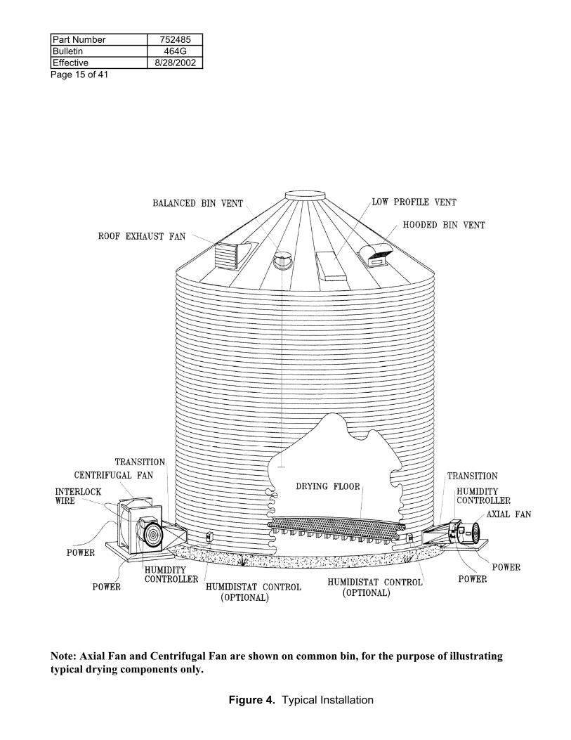
Note: Axial Fan and Centrifugal Fan are shown on common bin, for the purpose of illustrating typical drying components only.
Figure 4. Typical Installation
Part Number 752485Bulletin 464GEffective 8/28/2002
Page 16 of 41
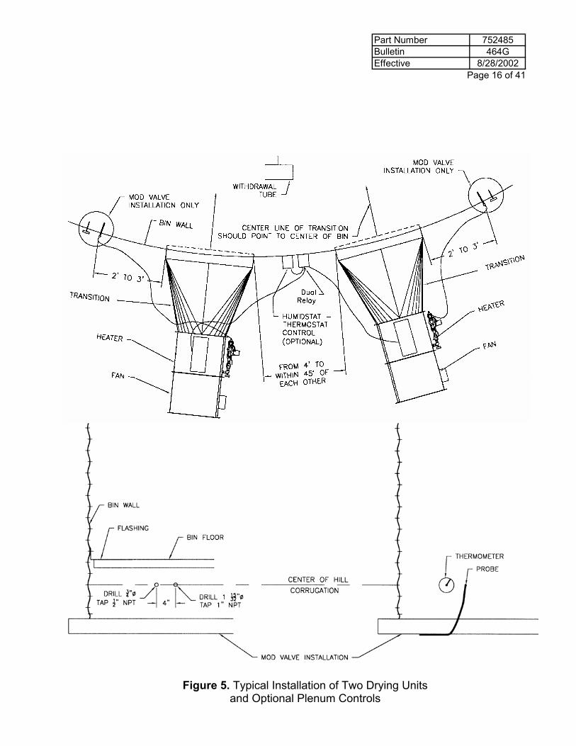
Figure 5. Typical Installation of Two Drying Units and Optional Plenum Controls
Part Number 752485Bulletin 464GEffective 8/28/2002 Page 17 of 41
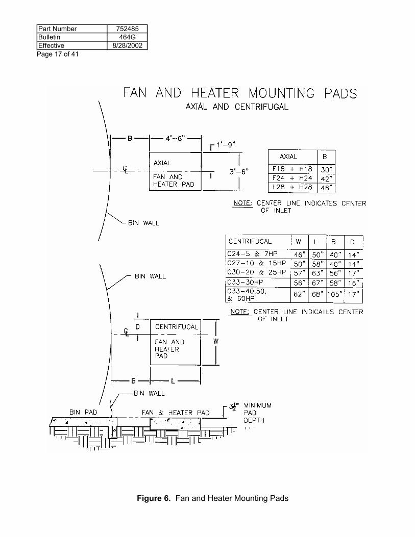
Figure 6. Fan and Heater Mounting Pads
Part Number 752485Bulletin 464GEffective 8/28/2002
Page 18 of 41
INSTALLATION INSTRUCTIONS
I. Application Determination of NGE-PE Units The H18-NGE-PE, H24-NGE-PE, H24-LT-NGE-PE, H28-LT-NGE-PE, H28-NGE-PE and
the H33-NGE-PE Units are shipped for propane fuel operation. Remove the fuel orifice for Natural Gas Operation of H24, H28 and H33 heaters. Use a 1/4" orifice for Natural Gas Operation of H18, H24LT and H28LT heaters.
II. Location and Foundation of the Heater
A. The drying unit (fan, heater, and transition) should be located such that the heated air can enter the bin plenum chamber uniformly. Figure 4 on page 15 illustrates the components necessary for a typical installation. Make sure all the components needed for the drying system are present. The fan and heater should be located opposite the withdrawal tube for best air distribution.
B. If two drying units are used on the same bin (Figure 5), locate them from 4’ to within 45° of each other and centered opposite the withdrawl tube. Locate any humidistat or thermostat control between the two heater units, making sure control senses heat from both units (order kit #735035.)
C. For proper operation of heater, the fan and heater are to be mounted on a level pad. The pad should be the same height as the concrete floor. The size of the pad should be as indicated in Figure 6 on page 17.
D. Before installing heater, make sure: 1. That the orifice is centered in the burner inlet. If necessary, loosen the setscrew
securing the heater plumbing where it passes through the heater housing, adjust the orifice location, and retighten the setscrew.
2. That if installing an H24-LPGE or H28-LPGE or H33-LPGE make sure the burner is located within ¼” of the vaporizer. If not, move the burner toward the vaporizer by loosening burner mounting carriage bolts, adjusting burner position and retightening the carriage bolts.
3. That the spark plug is gapped at 1/8”. If not, gap to 1/8". 4. That the flame probe and spark plug wires are attached. 5. That all bolts, carriage bolts and screws are tight.
E. On axial fan units, the heater is installed on the air discharge end of the fan. Check airflow decals on the fan and heater to make sure heater is oriented properly. The installation should appear as illustrated in Figure 4. On centrifugal fan units, the heater is mounted on the inlet side of the fan. Make sure the airflow decal is pointing toward the fan. The installation should appear as illustrated on page 15.
F. Connect the fan and heater together using the 5/16" bolts provided in the heater bolt bag. On axial units, connect the heater to the transition with the bolts provided in the fan bolt bag. On centrifugal units, connect the fan to the transition with the bolts provided in the fan bolt bag.
Part Number 752485Bulletin 464GEffective 8/28/2002 Page 19 of 41
III. Gas Supply Installation A. Propane Tank Installation: 1. A 1000-gallon tank is recommended as the minimum size to avoid frequent refilling.
(Raising the air temperature 100°F on an airflow rate of 10,000 CFM would require approximately 300 gallons of liquid propane per day.) In addition, the larger tank will aid in the vaporization of the liquid propane.
2. Never, use an anhydrous ammonia tank as your LP gas tank. Contaminants in the tank can be harmful to the heater, and safety devices may not meet liquid propane storage codes.
3. The supply tank should be placed at least 50 feet from the heater. Some areas may require a greater distance; consult your local authorities.
4. The supply tank should be equipped with a liquid valve and vapor valve. The inlet of the liquid valve should be located 12 inches from the tank bottom to avoid impurities getting into the gas line and heater.
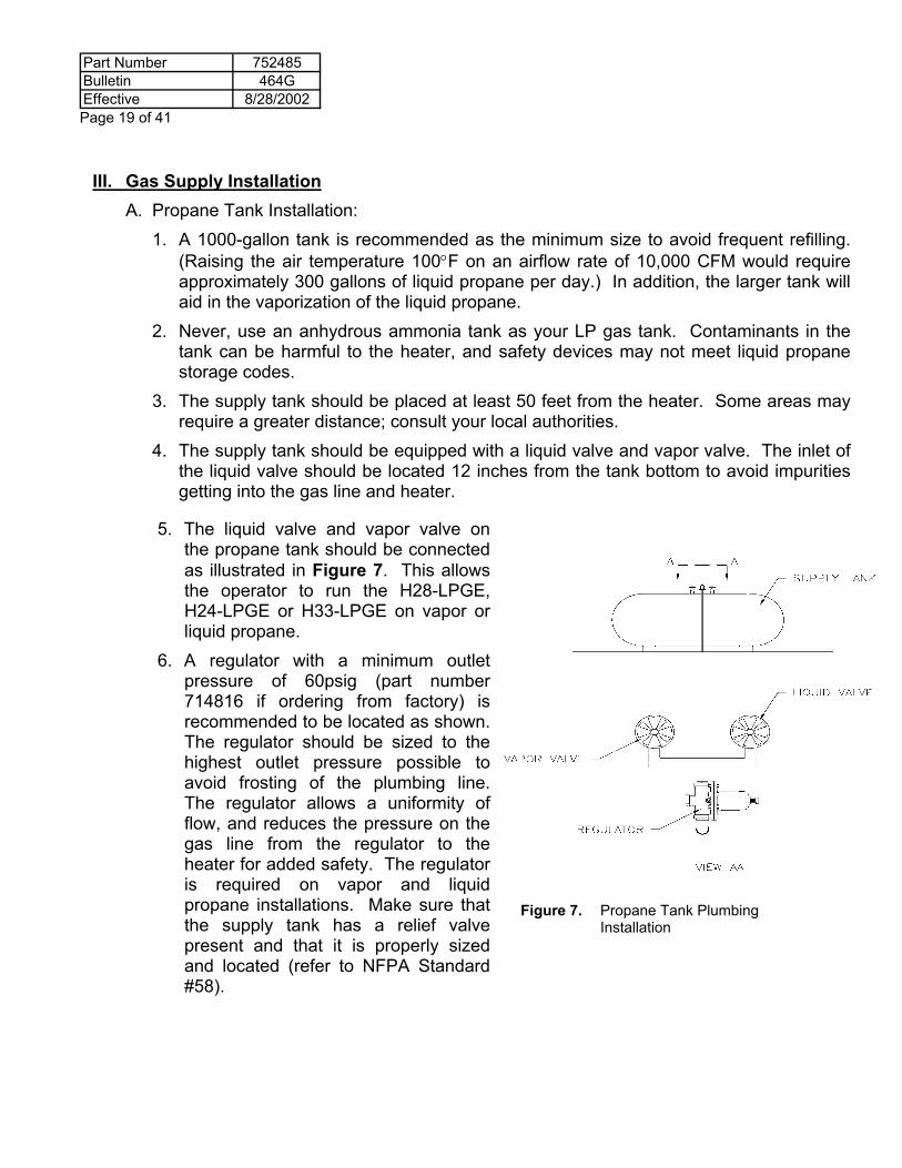
5. The liquid valve and vapor valve on the propane tank should be connected as illustrated in Figure 7. This allows the operator to run the H28-LPGE, H24-LPGE or H33-LPGE on vapor or liquid propane.
6. A regulator with a minimum outlet pressure of 60psig (part number 714816 if ordering from factory) is recommended to be located as shown. The regulator should be sized to the highest outlet pressure possible to avoid frosting of the plumbing line. The regulator allows a uniformity of flow, and reduces the pressure on the gas line from the regulator to the heater for added safety. The regulator is required on vapor and liquid propane installations. Make sure that the supply tank has a relief valve present and that it is properly sized and located (refer to NFPA Standard #58).
Figure 7. Propane Tank Plumbing Installation
Part Number 752485Bulletin 464GEffective 8/28/2002
Page 20 of 41
B. Natural Gas Installation: 1. The natural gas service should be able to provide (5) psig when the heater is
operating. Check with your gas supplier to make sure that the supply pressure has the pressure potential to deliver natural gas for the length of the service line
2. A line strainer must be located at the heater (order part #714709). 2. The natural gas service should be regulated. Contact your gas supplier. A regulator can be obtained from Caldwell (order part #753905).
C. Fuel Line Installation 1. The suggested tubing size to be used from the supply to the heater is 5/8" O.D.
type K copper tubing or 1/2" black schedule 80 steel pipe. If copper tubing is used, make a loop in the tubing within three feet of the heater to absorb shock. If 1/2" steel pipe is used, run the plumbing to within about three feet of the heater, and use three feet of 3/8" minimum I.D. high pressure hose, (UL approved for propane). Be careful not to turn or twist the heater plumbing parts because the proper operation of the heater plumbing parts can be affected and leaks in joints can be developed. Make sure all foreign material is out of the gas line before connecting the line to the heater.
2. If your natural gas supply pressure is not adequate to maintain five psig at the heater, use a one-inch or larger service line. Install a line strainer between the natural gas heater and the service line.
3. Check all connections for leaks with a soap test. Open the supply valve at the source, use a liquid detergent, and brush all fittings and joints. If bubbles are generated at the fitting, gas is escaping from the joint. With the installation of the service line, inspect all parts added, and heater plumbing parts affected by the installation. Tighten the components if not sealing, or replace if cracked or defective. DO NOT USE GALVANIZED PIPE FITTINGS.
Part Number 752485Bulletin 464GEffective 8/28/2002 Page 21 of 41
C. For fans wired for 460 or 575 volt, a step down transformer must be used to convert the 460 or 575 volt system to 115 volt, single phase, 60 cycle power for the heater.
D. When installing a thermostat, humidistat, or thermostat-humidistat control, the control power cord is wired into terminals three and four of the heater terminal block. Remove the jumper wire linking terminals three and four, and connect one lead of the control power cord to terminal three and the other lead to terminal four. The control leads can be interchanged.
V. Installation of Accessories For the proper installation of a thermostat, humidistat, or thermostat-humidistat control to
the bin, the installation of dual humidistat-thermostat kit, or the installation of vaporizer or modulating valve to the heater, refer to the installation instruction provided with each accessory.
IV. Electrical Installations A. Connect the fan unit to the electric power
source following the recommended wiring procedure indicated in the fan manual. Make sure all wiring conforms to the National Electric code, and local requirements.
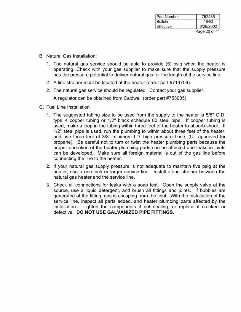
B. The heater operates on 115 volt, single phase, 60 cycle power. For fans wired for 230 volt, make sure that the fan is wired with a neutral wire to the middle terminal of the fan terminal block, (#2), as well as a ground wire linked to the bottom terminal of the fan terminal block, (#3), as shown. The heater power cord is wired into the fan controls by connecting the black wire to the terminal (#1), the white wire to terminal (#2), and the green wire to terminal (#3) of the fan terminal block, as shown in Figure 8. With the heater wired into the fan circuitry, the fan must be operating before power is available to the heater. On H18-NGE-PE units, the fan terminal block is included with the heater. Follow the installation instructions provided in installing the fan terminal block into the fan controls.
Figure 8. Heater Electrical Supply Connection
Part Number 752485Bulletin 464GEffective 8/28/2002
Page 22 of 41
SAFETY Before operating unit, perform the following checks: 1. Make sure the fan, heater, and transition units are bolted securely together. Make sure
the screen guard is secured in place. 2. Make sure the units are wired in compliance with the National Electrical Code, and the
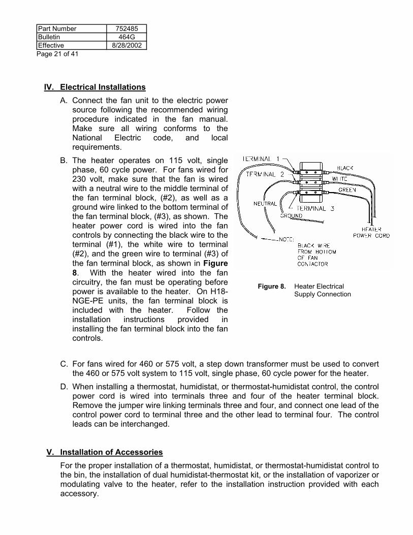
ground wire is sized large enough to provide lightening protection. 3. Make sure the gas supply installation is according to instructions. 4. Provide sufficient bin exhaust vents or fans, and make sure they are open or operational
before starting the drying system. The vents are necessary to provide an exhaust for moisture-laden air (to reduce condensation), and to prevent pressurization of the bin above the grain mass, causing added load on the bin. Do not operate units when conditions are such that freezing of the vents could occur.
HEED THE FOLLOWING WARNING:
Figure 9. BIN VENT WARNING DECAL
Part Number 752485Bulletin 464GEffective 8/28/2002 Page 23 of 41
OPERATING INSTRUCTIONS
WARNING: THE HEATER IS DESIGNED TO WORK AT VARYING FIRING RATES.
OPERATOR MUST ADJUST FIRING RATE FOR SYSTEM OPERATION BASED ON CONDITIONS PRESENT.
I. Start-Up Procedure A. Make sure all roof vents are open and unobstructed. Note: If freezing of roof vents
could occur, do not operate system. B. Make sure all controls are installed correctly. C. Turn fan on by placing fan switch to "On" position. D. Open Supply Valve at the Regulator: 1. It is preferable to start liquid propane units on vapor fuel. (After warmup, open
Liquid Valve on the supply tank approximately one turn, and close Vapor Valve.) E. Open Liquid Valve (on LPGE Heaters only). F. Check to make sure Burner High Limit Control Reset button is "In." G. Check to make sure Circuit Breaker with Time Delay Reset button is "In." H. Turn heater on by placing Toggle Switch to "On" position. I. Open Valve slowly to two psig fuel pressure for low temperature start. J. Set Plenum External Controls for desired heater operation. (See adjustment section
of this manual for more information.) K. The Regulator must be adjusted according to the information provided in the
adjustment section (Part III). (On LPGE Heaters Only) L. If burner fails to ignite in the five seconds, close Valve and turn off the heater by
placing Toggle Switch to the "Off" position. (Refer to service section of this manual for trouble shooting of heater.)
M. If the Burner High Limit shuts the burner off, reset heater after cooling down by pushing in the button located on top of the heater. The cycling of the Burner High Limit is caused by excessive static pressure or lack of airflow. Reduce the static pressure or air blockage before refiring unit.
Part Number 752485Bulletin 464GEffective 8/28/2002
Page 24 of 41
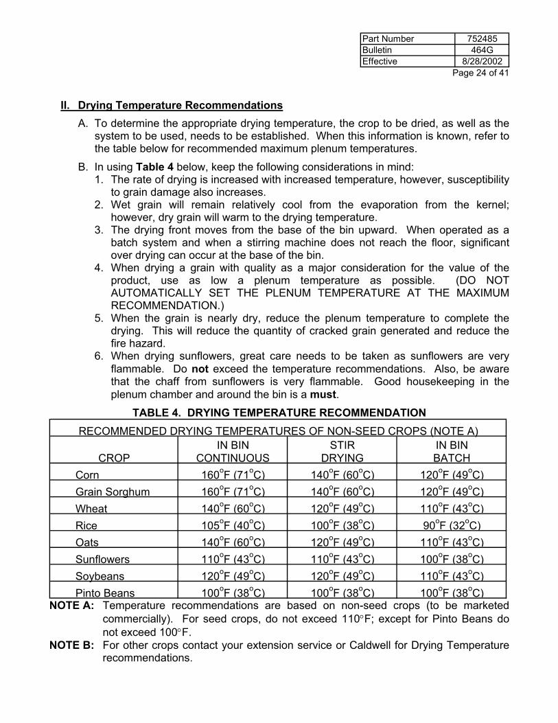
II. Drying Temperature Recommendations A. To determine the appropriate drying temperature, the crop to be dried, as well as the
system to be used, needs to be established. When this information is known, refer to the table below for recommended maximum plenum temperatures.
B. In using Table 4 below, keep the following considerations in mind: 1. The rate of drying is increased with increased temperature, however, susceptibility
to grain damage also increases. 2. Wet grain will remain relatively cool from the evaporation from the kernel;
however, dry grain will warm to the drying temperature. 3. The drying front moves from the base of the bin upward. When operated as a
batch system and when a stirring machine does not reach the floor, significant over drying can occur at the base of the bin.
4. When drying a grain with quality as a major consideration for the value of the product, use as low a plenum temperature as possible. (DO NOT AUTOMATICALLY SET THE PLENUM TEMPERATURE AT THE MAXIMUM RECOMMENDATION.)
5. When the grain is nearly dry, reduce the plenum temperature to complete the drying. This will reduce the quantity of cracked grain generated and reduce the fire hazard.
6. When drying sunflowers, great care needs to be taken as sunflowers are very flammable. Do not exceed the temperature recommendations. Also, be aware that the chaff from sunflowers is very flammable. Good housekeeping in the plenum chamber and around the bin is a must.
TABLE 4. DRYING TEMPERATURE RECOMMENDATION RECOMMENDED DRYING TEMPERATURES OF NON-SEED CROPS (NOTE A)
IN BIN STIR IN BINCROP CONTINUOUS DRYING BATCH
Corn 160oF (71oC) 140oF (60oC) 120oF (49oC)Grain Sorghum 160oF (71oC) 140oF (60oC) 120oF (49oC)Wheat 140oF (60oC) 120oF (49oC) 110oF (43oC)Rice 105oF (40oC) 100oF (38oC) 90oF (32oC)Oats 140oF (60oC) 120oF (49oC) 110oF (43oC)Sunflowers 110oF (43oC) 110oF (43oC) 100oF (38oC)Soybeans 120oF (49oC) 120oF (49oC) 110oF (43oC)Pinto Beans 100oF (38oC) 100oF (38oC) 100oF (38oC)
NOTE A: Temperature recommendations are based on non-seed crops (to be marketed commercially). For seed crops, do not exceed 110°F; except for Pinto Beans do not exceed 100°F.
NOTE B: For other crops contact your extension service or Caldwell for Drying Temperature recommendations.
Part Number 752485Bulletin 464GEffective 8/28/2002 Page 25 of 41
III. Adjustments The following adjustments will have to be made, depending upon the kind of heater, and
Plenum External controls being used. These adjustments cannot be made at the factory due to the differences in bin setups, drying methods, and weather climates. These adjustments should be checked at least twice a day or 6 hours of operation to make sure that the heater is functioning properly, and that the operator is getting the desired result.
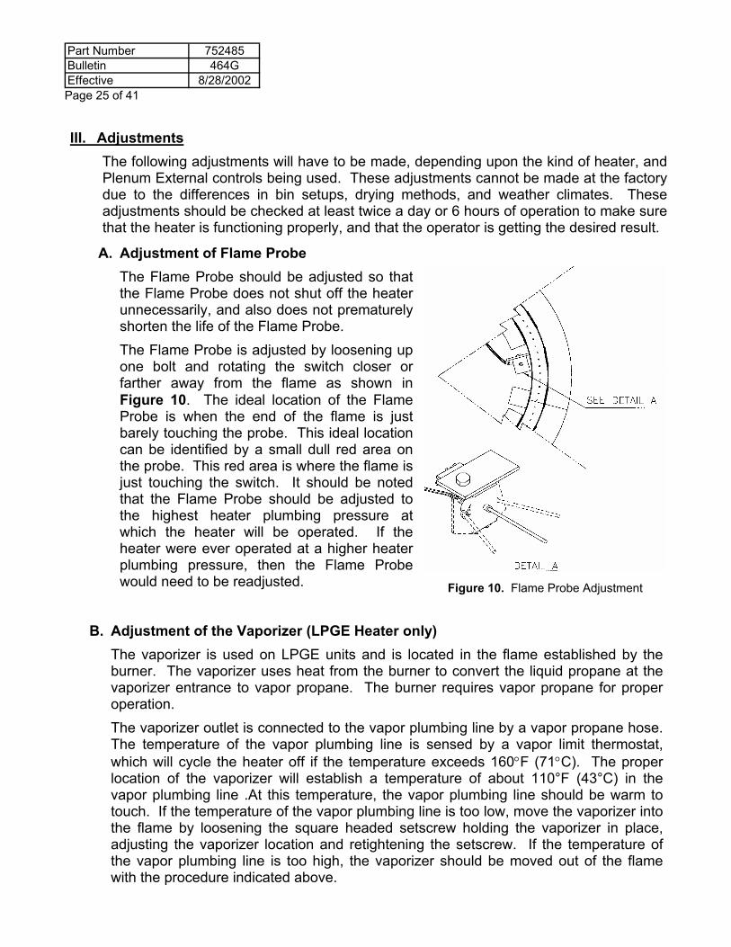
A. Adjustment of Flame Probe The Flame Probe should be adjusted so that
the Flame Probe does not shut off the heater unnecessarily, and also does not prematurely shorten the life of the Flame Probe.
The Flame Probe is adjusted by loosening up one bolt and rotating the switch closer or farther away from the flame as shown in Figure 10. The ideal location of the Flame Probe is when the end of the flame is just barely touching the probe. This ideal location can be identified by a small dull red area on the probe. This red area is where the flame is just touching the switch. It should be noted that the Flame Probe should be adjusted to the highest heater plumbing pressure at which the heater will be operated. If the heater were ever operated at a higher heater plumbing pressure, then the Flame Probe would need to be readjusted.
B. Adjustment of the Vaporizer (LPGE Heater only) The vaporizer is used on LPGE units and is located in the flame established by the
burner. The vaporizer uses heat from the burner to convert the liquid propane at the vaporizer entrance to vapor propane. The burner requires vapor propane for proper operation.
The vaporizer outlet is connected to the vapor plumbing line by a vapor propane hose. The temperature of the vapor plumbing line is sensed by a vapor limit thermostat, which will cycle the heater off if the temperature exceeds 160°F (71°C). The proper location of the vaporizer will establish a temperature of about 110°F (43°C) in the vapor plumbing line .At this temperature, the vapor plumbing line should be warm to touch. If the temperature of the vapor plumbing line is too low, move the vaporizer into the flame by loosening the square headed setscrew holding the vaporizer in place, adjusting the vaporizer location and retightening the setscrew. If the temperature of the vapor plumbing line is too high, the vaporizer should be moved out of the flame with the procedure indicated above.
Figure 10. Flame Probe Adjustment
Part Number 752485Bulletin 464GEffective 8/28/2002
Page 26 of 41
Note that the distance between the vaporizer and the burner should be maintained at ¼”, and then the vaporizer should be moved in and out of the flame. If the distance between the burner and vaporizer is larger than ¼”, the burner should be moved forward toward the vaporizer.
C. Adjustment of the Regulator The Regulator should be set at the firing rate required. This can be done by first
setting the heater to the desired firing rate with the vapor valve, then reopening the Vapor Valve and adjusting the Regulator by turning the adjusting screw until the pressure gauge shows the pressure at the desired firing rate pressure.
When setting the heater at the desired firing rate, the operator must take into account the heater size, the static pressure the fan is working against, the ambient temperature, orifice size, and fuel used and the type of plenum control. Refer to operation instructions for the humidistat, thermostat, or modulating valve. The Firing Rate Tables of this manual are set up to help the operator select the desired firing rate.
D. Adjustment of the Humidistat Control if used to Operate the Heater Set the Humidistat Control at the desired setting (50-60% R.H. Recommended). To
obtain even drying, adjust the firing rate of the heater unit so that the Humidistat maintains a constant humidity of the drying air. The heater should be set at a firing rate of approximately two psi gauge pressure for propane, or one psi gauge pressure for natural gas, and then adjusted to obtain operation of the heater the majority of the time. The heater firing rate must be checked as humidity conditions change.
E. Adjustment of the Thermostat Control if used to Operate the Heater Set the Thermostat Control to the desired temperature setting. Initially, set the firing
rate of the heater at two-psi gauge pressure for propane, or one-psi gauge pressure for natural gas. To obtain even drying, adjust the firing rate of the heater unit so that the thermostat calls for heat 90% of the time. The heater-firing rate must be checked as temperature conditions change. WARNING! THE PLENUM THERMOSTAT IS USED AS A DRYING THERMOSTAT, NOT AS A PLENUM HIGH LIMIT.
F. Adjustment of Humidistat-Thermostat Control if used to Operate the Heater 1. Using the Humidistat-Thermostat Control, as a Humidistat Control only: Set the thermostat at the lower temperature limit. This is the temperature wanted
for heater operation, whether the humidistat is calling for heat or not, (40-50°F is recommended). Set the humidistat and heater according to the humidistat instructions previously given.
2. Using the Humidistat-Thermostat Control as a Thermostat Control only: Set the humidistat at 100% relative humidity. Then adjust the thermostat and
heater controls according to the thermostat instructions given.
Part Number 752485Bulletin 464GEffective 8/28/2002 Page 27 of 41
3. Using the Humidistat-Thermostat Control as a combination: Set the humidistat and thermostat at the desired operating conditions. Then
adjust the firing rate of the heater according to the humidistat and thermostat instructions.
G. Adjustment of the Modulating Valve used as a Heater Control The Modulating Valve is used to maintain a constant plenum temperature by allowing
more gas to flow to the burner if the plenum temperature is lower than desired or by restricting the gas flow if the temperature is higher than desired.
To set the Modulating Valve, use the following procedures: 1. Determine what plenum temperature is desired. 2. Using the vapor valve, set the operating pressure at eight (8) psig for propane, or
three (3) psig for natural gas. 3. Adjust the "T" Handle of the valve until the bin thermometer maintains the desired
plenum temperature. The handle is turned in, (clockwise) to get a higher temperature, or out (counter-clockwise) to get a lower temperature.
4. Set the regulator two (2) psig higher than the Modulating Valve operating condition, by turning the Modulating Valve handle in two revolutions, adjusting the regulator to the desired pressure, and then resetting the Modulating to the desired plenum temperature.
IV. Shut-Down Procedures A. If heater is to be shut off for a prolonged period, carry out the following steps: 1. Close Fuel Valve at tank. 2. Allow the fuel to be burned out of the fuel line. 3. After the flame burns out, close Vapor Valve and Liquid Valve. 4. Turn off heater, placing Toggle Switch to "Off" position. 5. Allow fan to run for two minutes in order to cool off heater. Then shut fan off.
Shut off the power at the fan service disconnect. 6. The Thermostat or Humidistat External Plenum Controls should be removed and
stored in a clean, dry place.
Part Number 752485Bulletin 464GEffective 8/28/2002
Page 28 of 41
V. Explanation of Firing Rate Tables A. The following tables are to be used as a guide for setting the firing rate of the heater.
The values are an estimate and actual values may differ, depending upon the bin setup and weather conditions. Once the predicted firing rate is obtained, a bin thermometer should be used to determine the actual plenum temperature, and the firing rate should be adjusted to obtain the desired plenum temperature. Use the following procedures in conjunction with the "Drying Temperature Recommendations" on page 24, in determining the firing rate needed for your application:
1. Determine the ambient temperature at which the heater operates (outside
temperature). 2. Find the difference of the desired drying temperature and the ambient
temperature. This value is the temperature rise desired. 3. Use a static pressure gauge to determine the static pressure at which the fan and
heater are operating. 4. Refer to the table which lists the size of your heater, and the gas used, then for
the temperature rise desired, read the firing rate required for the static pressure of operation.
5. If the ambient temperature is 50°F, then steps B and C can be skipped and the firing rate can be read for your heater, gas used, and plenum temperature for 50°F ambient air.
NOTE 1: AS CONDITIONS VARY, THE FIRING RATE SHOULD BE
ADJUSTED TO OBTAIN THE DESIRED PLENUM TEMPERATURE.
NOTE 2: THE VALUES IN TABLES 7 AND 8 ARE BASED ON THE PERFORMANCES OF A 10 HP AXIAL FAN. FOR THE 7.5 HP AND 5 HP AXIAL FANS THE FIRING RATE WILL NEED TO BE SLIGHTLY LOWER FOR THE TEMPERATURE RISE DESIRED.
Part Number 752485Bulletin 464GEffective 8/28/2002 Page 29 of 41
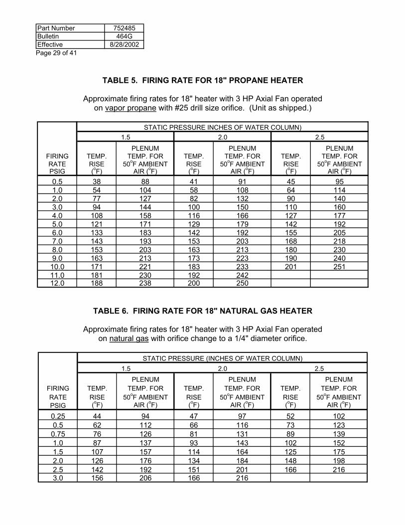
TABLE 5. FIRING RATE FOR 18" PROPANE HEATER
Approximate firing rates for 18" heater with 3 HP Axial Fan operated on vapor propane with #25 drill size orifice. (Unit as shipped.)
STATIC PRESSURE INCHES OF WATER COLUMN)
1.5 2.0 2.5
PLENUM PLENUM PLENUMFIRING TEMP. TEMP. FOR TEMP. TEMP. FOR TEMP. TEMP. FORRATE RISE 50oF AMBIENT RISE 50oF AMBIENT RISE 50oF AMBIENTPSIG (oF) AIR (oF) (oF) AIR (oF) (oF) AIR (oF)0.5 38 88 41 91 45 951.0 54 104 58 108 64 1142.0 77 127 82 132 90 1403.0 94 144 100 150 110 1604.0 108 158 116 166 127 1775.0 121 171 129 179 142 1926.0 133 183 142 192 155 2057.0 143 193 153 203 168 2188.0 153 203 163 213 180 2309.0 163 213 173 223 190 240
10.0 171 221 183 233 201 25111.0 181 230 192 24212.0 188 238 200 250
TABLE 6. FIRING RATE FOR 18" NATURAL GAS HEATER
Approximate firing rates for 18" heater with 3 HP Axial Fan operated on natural gas with orifice change to a 1/4" diameter orifice.
STATIC PRESSURE (INCHES OF WATER COLUMN)
1.5 2.0 2.5PLENUM PLENUM PLENUM
FIRING TEMP. TEMP. FOR TEMP. TEMP. FOR TEMP. TEMP. FORRATE RISE 50oF AMBIENT RISE 50oF AMBIENT RISE 50oF AMBIENTPSIG (oF) AIR (oF) (oF) AIR (oF) (oF) AIR (oF)
0.25 44 94 47 97 52 1020.5 62 112 66 116 73 1230.75 76 126 81 131 89 1391.0 87 137 93 143 102 1521.5 107 157 114 164 125 1752.0 126 176 134 184 148 1982.5 142 192 151 201 166 2163.0 156 206 166 216
Part Number 752485Bulletin 464GEffective 8/28/2002
Page 30 of 41
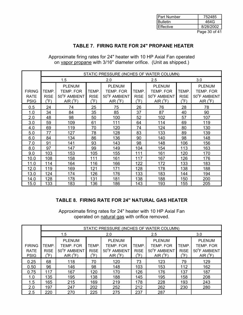
TABLE 7. FIRING RATE FOR 24" PROPANE HEATER
Approximate firing rates for 24" heater with 10 HP Axial Fan operated on vapor propane with 3/16" diameter orifice. (Unit as shipped.)
STATIC PRESSURE (INCHES OF WATER COLUMN)
1.5 2.0 2.5 3.0PLENUM PLENUM PLENUM PLENUM
FIRING TEMP. TEMP. FOR TEMP. TEMP. FOR TEMP. TEMP. FOR TEMP. TEMP. FORRATE RISE 50oF AMBIENT RISE 50oF AMBIENT RISE 50oF AMBIENT RISE 50oF AMBIENTPSIG (oF) AIR (oF) (oF) AIR (oF) (oF) AIR (oF) (oF) AIR (oF)0.5 24 74 25 75 26 76 28 781.0 34 84 35 85 37 87 40 902.0 48 98 50 100 52 102 57 1073.0 59 109 61 111 64 114 69 1194.0 69 119 70 120 74 124 80 1305.0 77 127 78 128 83 133 89 1396.0 84 134 86 136 90 140 98 1487.0 91 141 93 143 98 148 106 1568.0 97 147 99 149 104 154 113 1639.0 103 153 105 155 111 161 120 170
10.0 108 158 111 161 117 167 126 17611.0 114 164 116 166 122 172 133 18312.0 119 169 121 171 128 178 138 18813.0 124 174 126 176 133 183 144 19414.0 128 178 131 181 138 188 150 20015.0 133 183 136 186 143 193 155 205
TABLE 8. FIRING RATE FOR 24" NATURAL GAS HEATER
Approximate firing rates for 24" heater with 10 HP Axial Fan operated on natural gas with orifice removed.
STATIC PRESSURE (INCHES OF WATER COLUMN)
1.5 2.0 2.5 3.0PLENUM PLENUM PLENUM PLENUM
FIRING TEMP. TEMP. FOR TEMP. TEMP. FOR TEMP. TEMP. FOR TEMP. TEMP. FORRATE RISE 50oF AMBIENT RISE 50oF AMBIENT RISE 50oF AMBIENT RISE 50oF AMBIENTPSIG (oF) AIR (oF) (oF) AIR (oF) (oF) AIR (oF) (oF) AIR (oF)0.25 68 118 70 120 73 123 79 1290.50 96 146 98 148 103 153 112 1620.75 117 167 120 170 126 176 137 1871.0 135 195 138 188 145 195 158 2081.5 165 215 169 219 178 228 193 2432.0 197 247 202 252 212 262 230 2802.5 220 270 225 275 237 287
Part Number 752485Bulletin 464GEffective 8/28/2002 Page 31 of 41
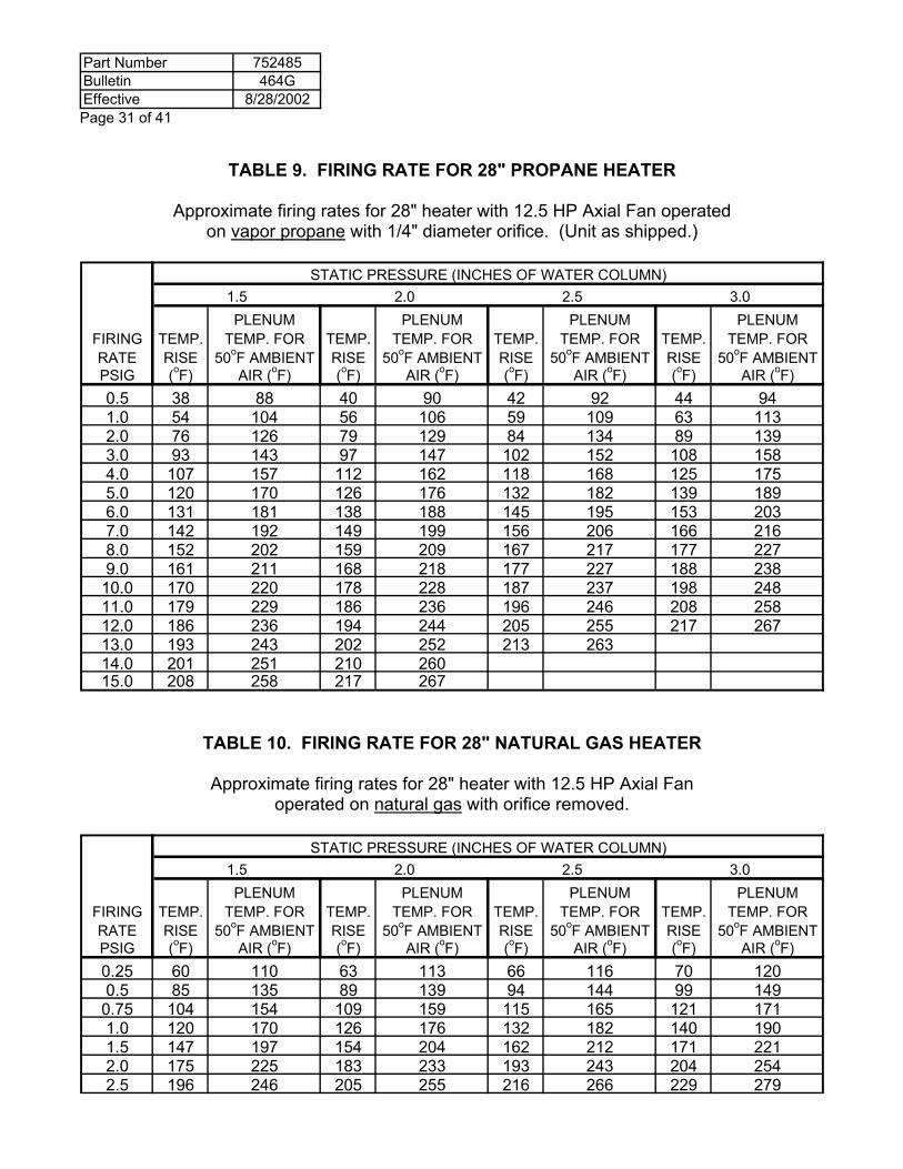
TABLE 9. FIRING RATE FOR 28" PROPANE HEATER
Approximate firing rates for 28" heater with 12.5 HP Axial Fan operated on vapor propane with 1/4" diameter orifice. (Unit as shipped.)
STATIC PRESSURE (INCHES OF WATER COLUMN)
1.5 2.0 2.5 3.0PLENUM PLENUM PLENUM PLENUM
FIRING TEMP. TEMP. FOR TEMP. TEMP. FOR TEMP. TEMP. FOR TEMP. TEMP. FORRATE RISE 50oF AMBIENT RISE 50oF AMBIENT RISE 50oF AMBIENT RISE 50oF AMBIENTPSIG (oF) AIR (oF) (oF) AIR (oF) (oF) AIR (oF) (oF) AIR (oF)0.5 38 88 40 90 42 92 44 941.0 54 104 56 106 59 109 63 1132.0 76 126 79 129 84 134 89 1393.0 93 143 97 147 102 152 108 1584.0 107 157 112 162 118 168 125 1755.0 120 170 126 176 132 182 139 1896.0 131 181 138 188 145 195 153 2037.0 142 192 149 199 156 206 166 2168.0 152 202 159 209 167 217 177 2279.0 161 211 168 218 177 227 188 238
10.0 170 220 178 228 187 237 198 24811.0 179 229 186 236 196 246 208 25812.0 186 236 194 244 205 255 217 26713.0 193 243 202 252 213 26314.0 201 251 210 26015.0 208 258 217 267
TABLE 10. FIRING RATE FOR 28" NATURAL GAS HEATER
Approximate firing rates for 28" heater with 12.5 HP Axial Fan operated on natural gas with orifice removed.
STATIC PRESSURE (INCHES OF WATER COLUMN)
1.5 2.0 2.5 3.0PLENUM PLENUM PLENUM PLENUM
FIRING TEMP. TEMP. FOR TEMP. TEMP. FOR TEMP. TEMP. FOR TEMP. TEMP. FORRATE RISE 50oF AMBIENT RISE 50oF AMBIENT RISE 50oF AMBIENT RISE 50oF AMBIENTPSIG (oF) AIR (oF) (oF) AIR (oF) (oF) AIR (oF) (oF) AIR (oF)0.25 60 110 63 113 66 116 70 1200.5 85 135 89 139 94 144 99 149
0.75 104 154 109 159 115 165 121 1711.0 120 170 126 176 132 182 140 1901.5 147 197 154 204 162 212 171 2212.0 175 225 183 233 193 243 204 2542.5 196 246 205 255 216 266 229 279
Part Number 752485Bulletin 464GEffective 8/28/2002
Page 32 of 41
HEATER MAINTENANCE
The following procedures should be followed and maintenance performed before starting the unit at the beginning of every season, and during operation. 1. The fuel line strainers should be taken out and cleaned. A plugged screen will restrict the
gas flow to the unit. On liquid propane units, liquid and vapor line strainers both should be checked. Warranty is void if the strainer or screen is removed, and not reinstalled after cleaning.
2. The burner ring should be checked to be sure that it is not plugged. Bugs and wasps can build nests in them. Use a piece of wire or drill bit that will fit the holes in the burner. To clean the inside of the ring, remove from the heater and tap lightly around the burner ring. Then pour the foreign material out of the Fuel Inlet Pipe.
3. The airswitch inlet screen should be cleaned. The screen keeps bugs and wasps from entering the airswitch; however, during operation the screen can become dirty.
4. Make sure the orifice and pipe are centered in the burner. It can be knocked out of adjustment. Loosen setscrew on heater plumbing bracket, adjust orifice and pipe, then retighten setscrew.
5. Check all plumbing joints for leaks using the "soap test." (See page 20 in installation instructions.)
6. Check all wires to see that they are not bare, causing a short. Mice eat away insulation if protection measures to control rodents are not taken (spark plug, flame probe, burner limit wires.)
7. Examine and gap spark plug. Through wear, the spark plug can go out of adjustment. Check during operation every two days. The gap of the plug should be 1/8 of an inch.
8. The flame probe needs to be checked to be sure that it has not burnt off due to not adjusting the flame probe in and out of the flame. The flame probe can also be broken. Check every two days during operation and replace or adjust as needed. (See adjustment section page 25).
9. Check all wire connections to be sure they are tight. 10. All external plenum controls (nylon humidistat and thermostat combination) should be
inspected, cleaned, and checked every three days during operation. 11. Caldwell recommends that external plenum controls be removed and stored in a clean,
dry place when not in use. 12. Check adjustment of vaporizer twice daily, or as changing weather conditions demand.
(See page 25 in heater adjustment section).
Part Number 752485Bulletin 464GEffective 8/28/2002 Page 33 of 41
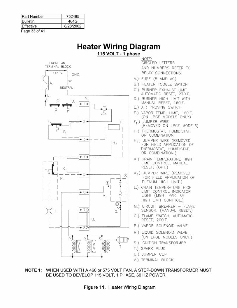
Heater Wiring Diagram 115 VOLT - 1 phase
NOTE 1: WHEN USED WITH A 460 or 575 VOLT FAN, A STEP-DOWN TRANSFORMER MUST
BE USED TO DEVELOP 115 VOLT, 1 PHASE, 60 HZ POWER.
Figure 11. Heater Wiring Diagram
Part Number 752485Bulletin 464GEffective 8/28/2002
Page 34 of 41
SERVICE SECTION
The following will help you find any problems that may occur in a Caldwell unit and tips for repairing the heater. For servicing of electrical systems, remove the control box cover. Inside the cover, you will find a wiring schematic or see Figure 11 on page 33 to help you service the unit. Find the symptoms you are experiencing with your unit and go through the possible causes and remedies. WARNING! UNLESS OTHERWISE INDICATED, CHECKS ARE MADE WITH THE POWER
OFF USING VOLTMETER ON RESISTANCE SETTING. Definition: Continuity - The ability to move electricity from one point to another, a completed circuit. I. SYMPTOM: TURN POWER SWITCH ON, NOTHING HAPPENS. 1. Lack of power going to the unit. (CHECK MADE WITH POWER ON). A. Take a voltmeter or continuity tester, put one lead to ground and the other on the
top terminal of terminal block in fan control box. Power lead is the black wire on top terminal on terminal block. It should indicate 115 volts on the voltmeter or light should come on with continuity tester.
2. Improper neutral. A. Check to be sure neutral wire is connected to the terminal block in the fan control
box. 1. Neutral needs to be provided from the disconnect to fan control box with the
power supply.
3. Check for power at toggle switch in heater. (POWER ON). A. Put one lead of voltmeter to toggle switch where power cord is connected and the
other lead to ground. If there is not any power, check cord and fuse.
4. Fuse may be blown. A. Visually check fuse. 1. If dark in color, replace. B. Check fuse and holder. 1. Put one lead on each side of the fuse on the fuse holder screws. Needle
should show continuity through fuse.
5. Burner High Limit and/or Burner Exhaust Limit may be open. A. Use voltmeter and check for continuity between the two leads going to Burner
channel. 1. Leads are attached to No. 1 on the terminal block and the No. 2 on the Toggle
Switch. B. If there is not continuity. 1. Reset high limit button. 2. Remove channel from heater.
Part Number 752485Bulletin 464GEffective 8/28/2002 Page 35 of 41
a. Check each switch individually by putting leads of meter to the two screws that have wires attached. The switch should show continuity. Replace switch if defective.
b. If switches are okay, then the burner limit wire is defective. Replace damaged wire.
6. Air Switch may be defective. A. Check to see if the air switch is the problem. 1. Move vapor limit switch lead from terminal No. 2 to terminal No. 3 on block and
switch on heater. If unit starts, the problem is the air switch. Reconnect wires to the original position after the test.
B. Make sure the air switch screen is not plugged. If the fan is working against 3" static pressure or higher, and any portion of the screen is open, the heater should run. Remove the screen and try operating the heater. If it runs without the screen, clean the screen and reinstall on the air switch intake.
C. Be sure air intake of the switch is not plugged. If the air intake is not plugged, replace the air switch.
D. Heaters applied on centrifugal fans require an airswitch static pressure probe kit for operation.
7. The vapor limit switch may be defective.
A. Use voltmeter and check between No. 2 on terminal block and No. 3 on terminal block. If there is not any continuity, replace switch. (Make sure that the vapor limit switch has had sufficient time to cool, and automatically reset.)
8. Thermostat or Humidistat Control May Be Open
A. Use a voltmeter and check continuity across the terminal block where the 2 leads of the control are connected.
B. If no Continuity is present 1. Check that the control setting to call for heater operation. 2. Check that the wires to the control are not broken. If either wire is damaged
replace the wire. 3. Replace entire Thermostat or Humidistat.
9. Circuit Breaker with Time Delay is not completing the circuit. (POWER ON.) A. Reset switch.
C. Short Circuit Breaker with an insulated screwdriver between terminal No. 1 and No. 4. If unit ignites, replace the circuit breaker. (Power on and toggle switch in "ON" position.) CAUTION: DO NOT TOUCH SCREW DRIVER SHAFT.
10. Check all wires and connections to be sure they are okay and correct. (See wiring schematic.)
Part Number 752485Bulletin 464GEffective 8/28/2002
Page 36 of 41
II. SYMPTOM: NO IGNITION, LACK OF IGNITION SPARK, GAS PRESENT. 1. Transformer is defective. (POWER ON). A. Take the cap holding the spark plug wire off and remove the spark plug wire from
the transformer. With the transformer energized, ground an insulated screwdriver and arc to the transformer post where spark was connected. CAUTION: DO NOT TOUCH SCREW DRIVER SHAFT.
1. If there is not any arc, or less than a 1/8" arc, replace transformer.
2. Spark plug wire is defective. (POWER ON). A. Take wire off spark plug and arc to heater. CAUTION: DO NOT TOUCH SPARK
PLUG WIRE MOUNTING TERMINAL. 1. If it does not arc, replace wire.
3. Spark plug is defective. A. Check gap of plug. Gap is 1/8. B. If above steps 1 and 2 check okay, replace spark plug.
III. SYMPTOM: NO IGNITION, LACK OF GAS WITH SPARK PRESENT. The check to make sure gas is present should be made after all the electrical component checks are made, and the electrical controls are confirmed to be functioning properly.
1. Lack of gas to heater. A. Check tank to see if ample pressure is available to start unit. 1. Unit requires 35 psig of propane pressure and five psig of natural gas available
at the unit for start up. B. Check to see if tank, regulator, or line going to the unit is blocked.
2. Check to see if solenoids are functioning. (POWER ON). A. Put your hand on the top of the solenoid and turn the heater toggle switch on and
off several times. 1. If you feel a click at the top of the solenoid, the coil is okay and the solenoid is
functioning electrically. 2. If there is not a click, the coil is defective. Replace part. B. Check solenoid to see if screen is plugged in the solenoid or the diaphragm is
defective. 1. Unscrew the top of the brass fixture and the screen and diaphragm are located
just inside. a. Be sure to reassemble properly. Reversing any parts in the solenoid will
cause the solenoid not to function properly. b. Keep all foreign material out of solenoid.
Part Number 752485Bulletin 464GEffective 8/28/2002 Page 37 of 41
3. Obstruction in the gas line. Inspect the line strainers. Remove any foreign material found in the screens. NOTE: FOR NATURAL GAS HEATER, GO DIRECTLY TO STEP C.
WARNING: THE CHECKS IN THESE SECTIONS MUST BE MADE WITHOUT ANY SPARK OR FLAME IN THE IMMEDIATE AREA. DISCONNECT SPARK PLUG WIRE FROM TRANSFORMER, AND EXTINGUISH ANY FLAMMABLE MATERIALS.
A. Remove vaporizer hose where it is attached to the heater liquid solenoid. Leave gas supply on. Turn toggle switch on and then immediately off.
1. If there is very little gas coming out the solenoid, the obstruction is in the heater liquid plumbing or in the tank and line coming to the unit. a. Remove pressure relief valve. If there is pressure when the ball valve is
open, the restriction is the solenoid. B. Disconnect the vaporizer hose at the vapor regulator with the hose reattached to
heater liquid plumbing. Turn on the heater. Again, there should be a large volume of gas coming out the vaporizer hose.
1. If the vapor line strainer is okay, the vaporizer must be plugged. Replace vaporizer.
C. Obstruction is located in heater vapor plumbing. 1. Shut off gate valve and remove the solenoid. Turn on switch and open the
vapor valve. a. If gas is present at the point where the solenoid is attached, the solenoid
must be defective. Replace the solenoid. b. If gas is not present, the regulator is defective. Replace the regulator.
4. If there is gas present at the pressure gauge, but the unit lacks gas for ignition. A. Check orifice to be sure it is clean and the correct size is in use. (See Firing Rate
Tables.) B. Check burner ring. 1. See that holes are not plugged. 2. See that the tubing is not plugged by bugs or mice. (See maintenance section,
page 32.)
Part Number 752485Bulletin 464GEffective 8/28/2002
Page 38 of 41
IV. SYMPTOM: CIRCUIT BREAKER WITH TIME DELAY POPS OUT. 1. If ignition is not present. A. Refer to Symptom III, if spark is present and gas is not available. B. Refer to Symptom II, if gas is present and you are lacking spark.
2. Ignition is present. A. Check position of the flame probe for proper adjustment. (See page 25 in
adjustment section.) B. Defective flame probe. 1. Remove one of the flame probe wires from the flame probe. If the unit runs,
the problem is the flame probe. Replace the flame probe. C. Check the flame probe wire. If defective, replace. 1. Check wire for bare spots and shorts to ground. a. Flame probe should not show continuity from either wire to ground. 2. Check the two wires in the flame probe wire assembly to see if they are
shorting across in the assembly. a. With the wires removed from the flame probe, there should not be any
continuity. D. Defective Circuit Breaker with Time Delay. (POWER ON). 1. Shut off gas supply at vapor line valve. Push time delay button in. Turn on
toggle switch and time the Circuit Breaker with Time Delay. Circuit Breaker button should pop out in 20 to 50 seconds. If the button does not pop out within this time span, replace the Circuit Breaker with Time Delay.
2. If A, B and C check out okay, that leaves only the Circuit Breaker with Time Delay to be defective. Replace this part.
V. SYMPTOM: BURNER HIGH LIMIT POPS OUT. 1. Fan inlet obstructed. A. Keep fan screen clean of all foreign material.
2. Fan motor failing. A. Have motor checked to see that it is coming up to full speed.
3. See if static pressure is too high. Use static pressure gauge. A. Check to be sure roof vents are open and the openings are sufficient in size. B. Check floor for plugged holes. C. Check grain depth, moisture content, and fines in grain. If any of these conditions
are high, the grain level should be lowered.
Part Number 752485Bulletin 464GEffective 8/28/2002 Page 39 of 41
VI. SYMPTOM: HEATER CYCLES WITHOUT ANY EXTERNAL PLENUM CONTROLS IN
USE. (POWER ON). 1. Static pressure too high, causing Burner Exhaust Limit to cycle the unit. A. Remove vapor temperature limit from the vapor plumbing line. If unit continues to
cycle, check the following. 1. The vent area in the bin roof. a. Are vents open? b. Is the amount of openings sufficient? 2. The firing rate is too high for the application. (See Firing Rate Tables.) 3. Check the grain depth, fines and moisture content. If these conditions are
high, the grain level should be lowered.
2. The Vaporizer is too hot. A. Remove vapor temperature limit from plumbing line. 1. If cycling stops, adjust vaporizer out of the flame. (See page 25 in adjustment
section.) VII. SYMPTOM: NOT ENOUGH HEAT
1. Orifice is too small or dirty. A. Check Firing Rate Tables for the proper size orifice for your unit and application. 1. Natural gas unit requires the orifice to be removed on 24" and 28" units. B. Remove orifice and check for obstructions and then reinstall orifice. 2. Insufficient gas pressure. A. Refer to installation section page 19 for proper gas supply.
3. Vaporizer not hot enough. A. Vapor plumbing will be cold to touch. 1. Refer to page 25 in adjustment section. VIII. SYMPTOM: EXTERNAL PLENUM CONTROL NOT FUNCTIONING. 1. Check wiring schematic and be sure the control is wired into the heater
properly. 2. Make visual check of the external plenum control cord to be sure it isn't cut or
shorted. 3. Check the external plenum control setting. Adjust external plenum control for
desired setting, using page 26 in adjustment section.
Part Number 752485Bulletin 464GEffective 8/28/2002
Page 40 of 41
PRODUCT SERVICE: Our top priority is to assure customer satisfaction on all Caldwell products. If a dealer requires assistance from Caldwell, contact our Service Department. The dealer purchasing a product from Caldwell will be responsible for the installation, operation, and service in accordance with Caldwell Service Policy. The dealer will also be responsible for all Standard Limited Warranty procedures in accordance with Caldwell Service Policy.
SERVICE POLICY CALDWELL STANDARD LIMITED WARRANTY: DEALERS HAVE THE RESPONSIBILITY OF CALLING TO THE ATTENTION OF THEIR CUSTOMERS THE FOLLOWING LIMITED WARRANTY, PRIOR TO ACCEPTANCE OF AN ORDER FROM THE CUSTOMER FOR ALL COMPANY PRODUCTS. Caldwell warrants to the purchaser for use that if any part of the product is proven to be defective in material or workmanship with 2 years from date of original invoice from factory, and Caldwell is notified within 15 days after such defect is discovered, Caldwell, will (at company option) either replace or repair said part. This standard limited warranty does not apply to damage resulting from misuse, neglect, material wear, accident or improper installation or maintenance. Said part will not be considered defective if it substantially fulfills performance specifications. THE FOREGOING LIMITED WARRANTY IS EXCLUSIVE AND IN LIEU OF ALL OTHER WARRANTIES OF MERCHANTABILITY, FITNESS FOR PURPOSE AND OF ANY OTHER TYPE, WHETHER EXPRESSED OR IMPLIED. Caldwell neither assumes nor authorizes anyone to assume for it any other obligation or liability in connection with said part and will not be liable for incidental or consequential damages. THE REMEDIES STATED HEREIN SHALL BE THE EXCLUSIVE REMEDIES AVAILABLE UNDER THIS STANDARD LIMITED WARRANTY. CLAIMS UNDER THIS STANDARD LIMITED WARRANTY SHALL BE HANDLED UNDER THE STANDARD SERVICE POLICY. Caldwell will not be responsible for any charges incurred in repairing or servicing any Caldwell products except as such repairs are made at Caldwell or by Caldwell Field Service Personnel or as approved in writing from Caldwell Customer Service. IN WARRANTY REPLACEMENT: The Caldwell Standard Limited Warranty Policy will cover any defective part of the product covered by the Standard Limited Warranty. Equipment involved in a warranty claim under the above Standard Limited Warranty shall have the ORIGINAL WARRANTY REGISTRATIOIN CARD on file in Kearney, Nebraska, and have been properly installed, maintained and operated according to the instructions provided by Caldwell. WARRANTY CLAIM PROCEDURES: When a part failure occurs, that in your judgment meets the conditions of the above Standard Limited Warranty, contact your dealer to make arrangements for the shipment of a replacement item and the return of the defective equipment. ELECTRIC MOTOR WARRANTY: The Manufacturers of all electric motors used by Caldwell carry a warranty for these items. If the motor fails under the conditions of the Caldwell Standard Limited Warranty Policy, and provided it was protected by the proper protective device, the motor manufacturer's nearest authorized service center will repair it. See catalog for motor manufacturers service centers. Any in warranty replacement motors not satisfactorily handled by motor manufacturer service centers and within the Standard Limited Warranty period and policy will be covered by Caldwell, Kearney, Nebraska. Contact Caldwell if you have any problems or questions. OUT OF WARRANTY SERVICE: Products requiring Caldwell repair work will be repaired at the standard repair charge plus hourly charges after the first hour. Field service work will require a field service charge plus travel expenses. The repaired part will carry a 30 day limited warranty. Your dealer will be responsible for warranty procedures in accordance with the Caldwell Service Policy. (See Dealer Policy.)
Part Number 752485Bulletin 464GEffective 8/28/2002 Page 41 of 41
NOTES