Embed Size (px)
Citation preview

Calibration and Correction of Compact Polarimetric
SAR DataJun Hong1,3,4, Hong Tan2,3,4, Wen Hong1,3,4
1. National Key Laboratory of Microwave Imaging Technology, Beijing 100190, China;2. Key Laboratory of Technology in Geo-spatial Information Processing and Application
System,Chinese Academy of Sciences, Beijing 100190, China;3. Institute of Electronics,Chinese Academy of Sciences, Beijing 100190, China;
4. University of Chinese Academy of Sciences, Beijing 100039, China
23rd CEOS SAR Cal&Val Workshop

Concept
Compact polarimetric (CP) synthetic aperture radar (SAR)
Three typical modes Tran Rec1 Rec2
π/2
CTLR(Circular Transmit and
Linear Receive)R H V
DCP(Dual Circular Polarimetry)
R R L
π/4 45° H V
2

Advantages
Compared to a fully polarimetric (FP) system• Lower PRF• Wider swath• Lower data rate• Much lower energy consumption• lower cost and lower mass• Most importantly, reconstructed pseudo quad-
polarimetric information can be used in a similar way as the FP data
• Specially, the transmitted polarization is not affected by Faraday rotation in the CTLR and DCP modes
3
Current CP SAR systems
IndiaRISAT-1
2012
JapanALOS-2
(Experiment mode)2014
CanadaRCM
(Including 3 satellites)2018 as planed
4

Challenges
As a polarimetric SAR system, polarimetric distortions must be determined and corrected.• Very few measurements• Too many unknowns• Quite different from the calibration of the FP
SAR system
5

Previous work
1. System models• 2005, Souyris
– Use one cross talk to describe all distortions of the transmitting system
• 2008, Freeman– Take the Faraday rotation into account– Consider cross talks and channel imbalance of the
transmitted antenna instead of one distortion• 2014, Touzi
– Raise the question of nonideal transmitted polarized signal, such as an elliptical polarized signal is transmitted instead of an circular polarized one for the reason of a phase error between the horizontal and vertical antennas
6
Previous work
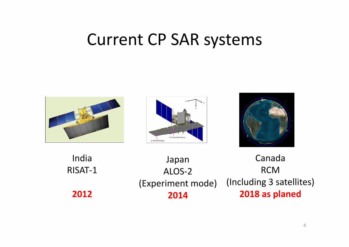
2. Calibration methods• A) Methods based on manmade calibrators• 2008, Freeman
– Three calibrators: Trihedral + 0°Dihedral + 45°Dihedral– Calibrated parameters: receiving distortions, Faraday
rotation angle• 2011, Jie Chen
– Calibrators: several different combination of active and passive calibrators
– Calibrated parameters: receiving distortions, Faraday rotation angle, and transmitting distortions
7

Previous work
2. Calibration methods• B) Methods based on natural distributed
targets• 2005, Souyris
– Raised the possibility of calibration with natural distributed targets
• 2009, Truong-Loï– Estimate the Faraday rotation angle using natural
distributed targets under certain conditions
8
Previous work
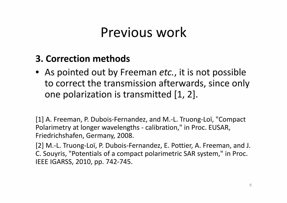
3. Correction methods• As pointed out by Freeman etc., it is not possible
to correct the transmission afterwards, since only one polarization is transmitted [1, 2].
[1] A. Freeman, P. Dubois-Fernandez, and M.-L. Truong-Loï, "Compact Polarimetry at longer wavelengths - calibration," in Proc. EUSAR, Friedrichshafen, Germany, 2008.[2] M.-L. Truong-Loï, P. Dubois-Fernandez, E. Pottier, A. Freeman, and J. C. Souyris, "Potentials of a compact polarimetric SAR system," in Proc. IEEE IGARSS, 2010, pp. 742-745.
9

Our focus
• 1. System model– Some distortions are not considered
• 2. Calibration methods– Methods based on manmade calibrators use at
least three calibrators and are costly– The question for calibration based on distributed
targets is ill-positioned• 3. Correction methods
– Transmitted distortions can not be corrected afterwards
10
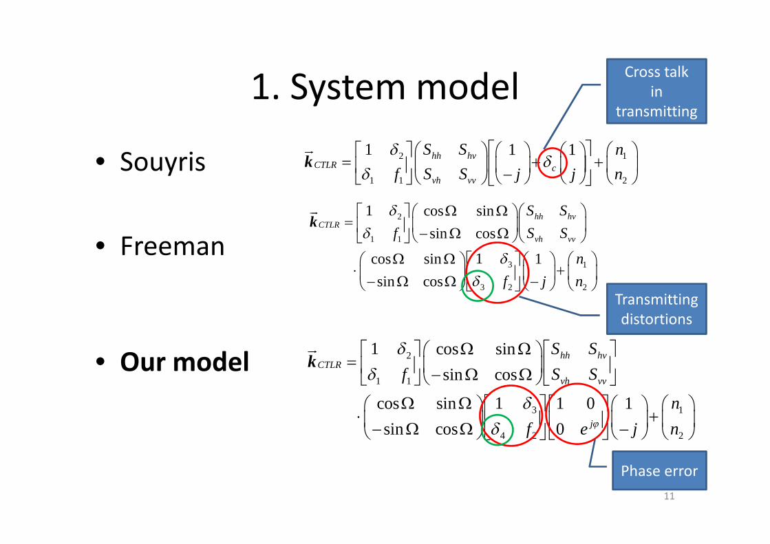
1. System model
• Souyris
• Freeman
• Our model
2 1
1 1 2
1 1 1hh hvCTLR c
vh vv
S S n
S Sf nj j
dd
dé ùæ öé ù æ öæ ö æ ö
= + +ê úç ÷ ç ÷ç ÷ ç ÷ê ú -è ø è øë û è øè ø ë ûkur
2
1 1
3 1
3 2 2
1 cos sin
sin cos
1cos sin 1
sin cos
hh hvCTLR
vh vv
S S
S Sf
n
f nj
dd
dd
W W æ öé ù æ ö= ç ÷ç ÷ê ú - W Wè øë û è ø
W W é ù æ öæ ö æ ö× + ç ÷ç ÷ ç ÷ê ú- W W -è ø è ø è øë û
kur
2
1 1
3 1
4 2 2
1 cos sin
sin cos
1cos sin 1 0 1
sin cos 0
hh hvCTLR
vh vv
j
S S
S Sf
n
f ne jj
dd
dd
W W é ùé ù æ ö= ç ÷ ê úê ú - W Wè øë û ë û
W W é ù æ öæ ö é ù æ ö× + ç ÷ç ÷ ç ÷ê ú ê ú- W W -è ø ë û è øë û è ø
kur
Phase error
Cross talkin
transmitting
Transmitting distortions
11
2. Calibration method
To reduce the number of deployed calibrators, we propose a calibration method using distributed targets and one corner reflector [3].
[3] Hong Tan, Jun Hong. Calibration of Compact polarimetric SAR Images Using Distributed Targets and One Corner Reflector[J], IEEE Trans. Geosci. Remote Sens., 54(8): 4433-4444, 2016.
12

2. Calibration method
• Assuming– A homogeneous distributed target that respects
both the reflection symmetry and the rotation symmetry exists
• For– A reciprocal system
• With– The phase shift error small and negligible– The Faraday rotation angle already measured
externally (such as estimation from TEC models) 13
2. Calibration method
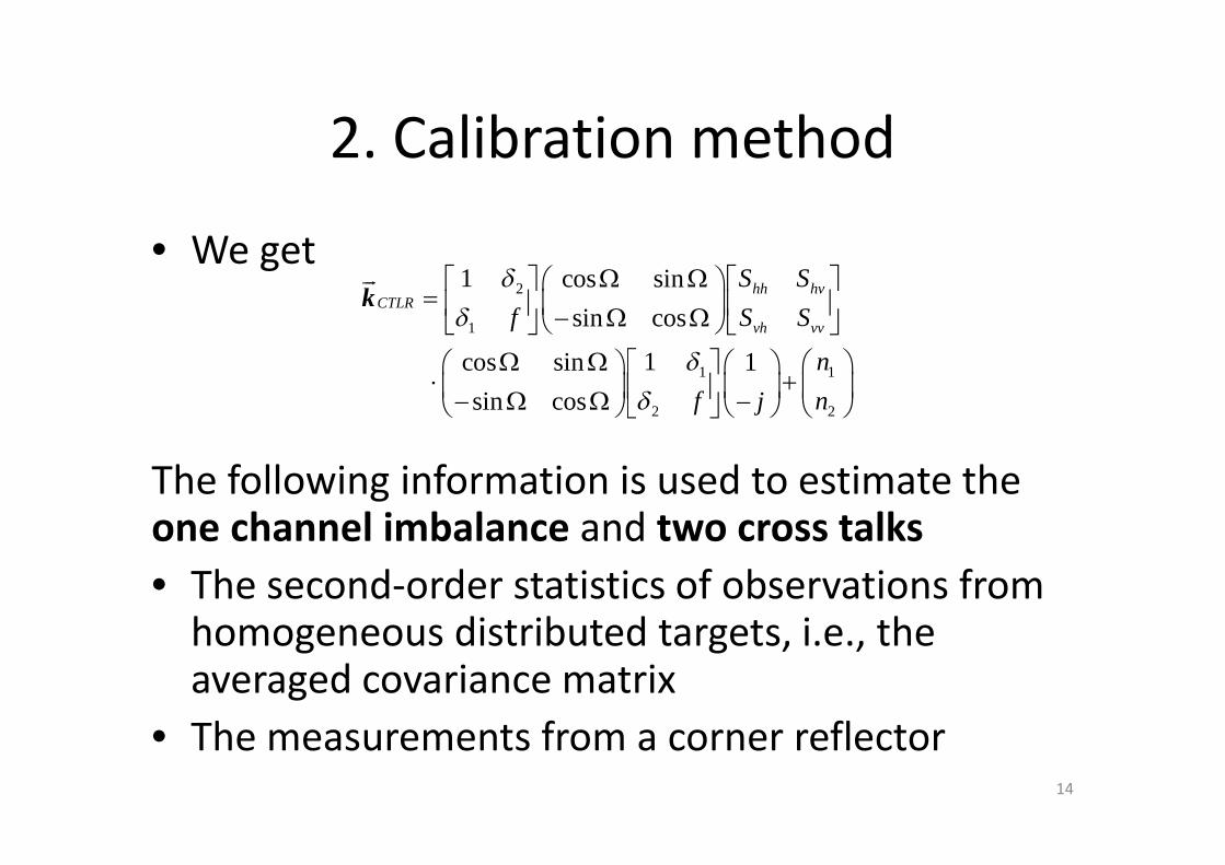
• We get
The following information is used to estimate the one channel imbalance and two cross talks• The second-order statistics of observations from
homogeneous distributed targets, i.e., the averaged covariance matrix
• The measurements from a corner reflector
2
1
1 1
2 2
1 cos sin
sin cos
1cos sin 1
sin cos
hh hvCTLR
vh vv
S S
S Sf
n
f nj
dd
dd
W W é ùé ù æ ö= ç ÷ ê úê ú - W Wè øë û ë û
W W é ù æ öæ ö æ ö× + ç ÷ç ÷ ç ÷ê ú- W W -è ø è øë û è ø
urk
14
2. Calibration method
A set of full polarimetric single-look complex L-band data over the Amazon rainforest from ALOS PALSAR is selected to simulate CP SAR measurements
15

2. Calibration method
Distortion parameters in simulation
16

2. Calibration method• SVD decomposition of Jacobian matrix• Three typical corner reflcetors are analyzed• Dihedral corner reflector at 0 deg is selected as the best in existance of
background noises, and is used in the following simulation
0 2 4 6 8 10-80
-60
-40
-20
0
20p/4 Mode
Eigenv alue number
Ene
rgy
(dB
)
Trihedral
Dihedral at 0
Dihedral at 45
0 2 4 6 8 10-80
-60
-40
-20
0
20DCP Mode
Eigenv alue number
Ene
rgy
(dB
)
0 2 4 6 8 10-80
-60
-40
-20
0
20CTLR Mode
Eigenv alue number
Ene
rgy
(dB
)
Largest value
17
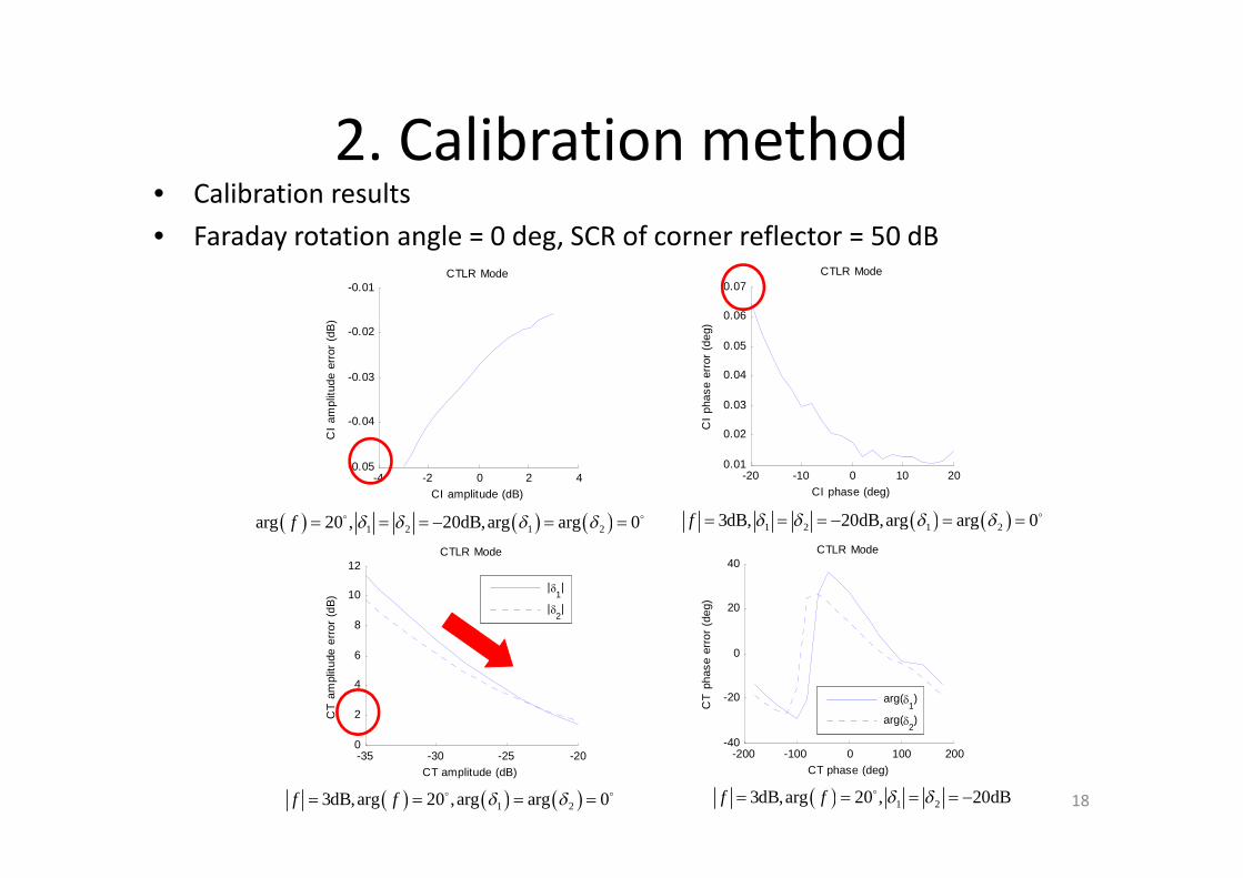
2. Calibration method• Calibration results• Faraday rotation angle = 0 deg, SCR of corner reflector = 50 dB
-4 -2 0 2 4-0.05
-0.04
-0.03
-0.02
-0.01CTLR Mode
CI amplitude (dB)
CI
ampl
itude
err
or (
dB)
-20 -10 0 10 200.01
0.02
0.03
0.04
0.05
0.06
0.07CTLR Mode
CI phase (deg)
CI
phas
e er
ror
(deg
)
-35 -30 -25 -200
2
4
6
8
10
12CTLR Mode
CT amplitude (dB)
CT
am
plitu
de e
rror
(dB
)
|d
1|
|d2|
-200 -100 0 100 200-40
-20
0
20
40CTLR Mode
CT phase (deg)
CT
pha
se e
rror
(de
g)
arg(d1)
arg(d2)
( ) ( ) ( )1 2 1 2arg 20 , 20dB,arg arg 0f d d d d= = = - = =o o ( ) ( )1 2 1 23dB, 20dB,arg arg 0f d d d d= = = - = = o
( ) ( ) ( )1 23dB,arg 20 ,arg arg 0f f d d= = = =o o ( ) 1 23dB,arg 20 , 20dBf f d d= = = = -o18
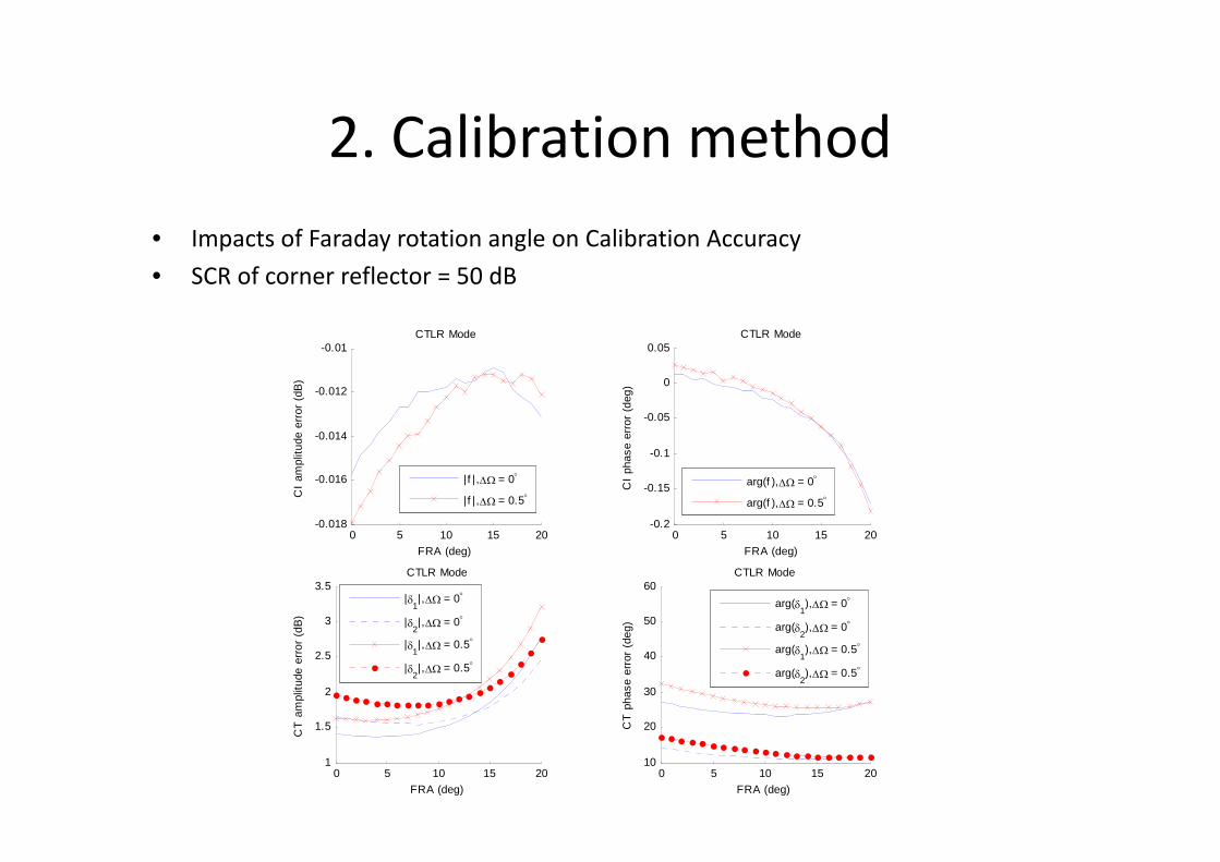
2. Calibration method• Impacts of Faraday rotation angle on Calibration Accuracy• SCR of corner reflector = 50 dB
0 5 10 15 20-0.018
-0.016
-0.014
-0.012
-0.01CTLR Mode
FRA (deg)
CI
ampl
itude
err
or (
dB)
|f | ,DW = 0°
| f | ,DW = 0.5°
0 5 10 15 20-0.2
-0.15
-0.1
-0.05
0
0.05CTLR Mode
FRA (deg)
CI
phas
e er
ror
(deg
)
arg(f ),DW = 0°
arg(f ),DW = 0.5°
0 5 10 15 201
1.5
2
2.5
3
3.5CTLR Mode
FRA (deg)
CT
am
plitu
de e
rror
(dB
)
|d
1|,DW = 0°
|d2|,DW = 0°
|d1|,DW = 0.5°
|d2|,DW = 0.5°
0 5 10 15 2010
20
30
40
50
60CTLR Mode
FRA (deg)
CT
pha
se e
rror
(de
g)
arg(d
1),DW = 0°
arg(d2),DW = 0°
arg(d1),DW = 0.5°
arg(d2),DW = 0.5°

2. Calibration method
AVERAGE OF ABSOLUTE CHANGE IN ABSOLUTEESTIMATION ERRORS CAUSED BY THE EXISTENCE OF AN
FRA ERROR
Parameters π/4 DCP CTLR
(dB) 0.01 0.00 0.00
(deg) 0.06 0.01 0.01
(dB) 0.87 0.29 0.29
(deg) 1.96 2.85 2.85
(dB) 0.63 0.27 0.27
(deg) 2.13 1.66 1.66
f
( )arg f
1d
( )1arg d
2d
( )2arg d20
20 30 40 50 600
5
10
15
20
25
30CTLR Mode
SCR (dB)
CT
pha
se e
rror
(de
g)
arg(d1)
arg(d2)
20 30 40 50 601
2
3
4
5
6CTLR Mode
SCR (dB)
CT
am
plitu
de e
rror
(dB
)
|d
1|
|d2|
20 30 40 50 60-0.6
-0.4
-0.2
0
0.2CTLR Mode
SCR (dB)
CI
phas
e er
ror
(deg
)
20 30 40 50 60-0.12
-0.1
-0.08
-0.06
-0.04
-0.02
0CTLR Mode
SCR (dB)
CI
ampl
itude
err
or (
dB)
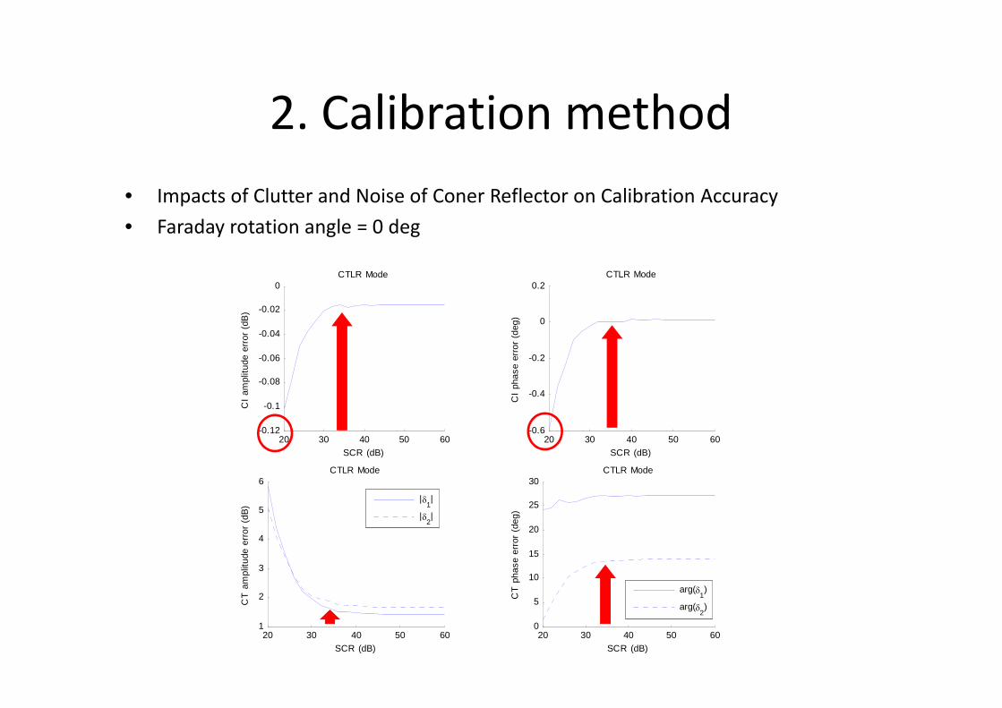
2. Calibration method• Impacts of Clutter and Noise of Coner Reflector on Calibration Accuracy• Faraday rotation angle = 0 deg
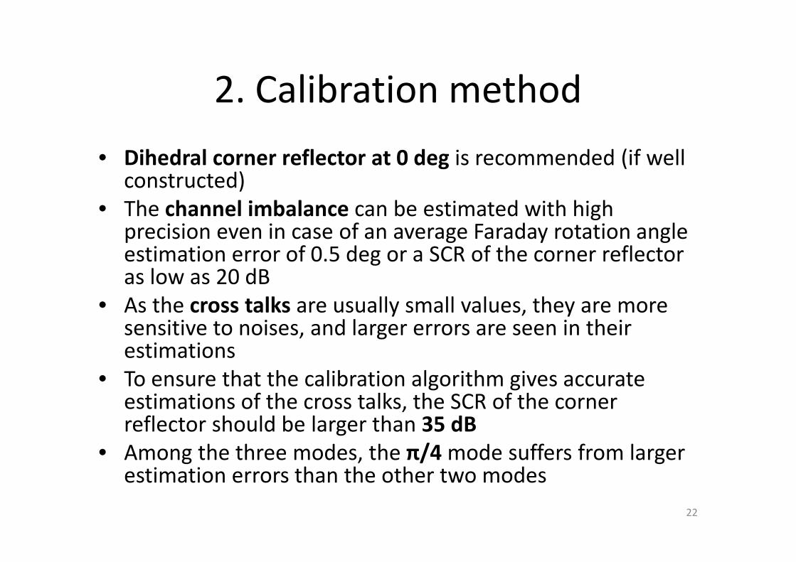
2. Calibration method• Dihedral corner reflector at 0 deg is recommended (if well
constructed)• The channel imbalance can be estimated with high
precision even in case of an average Faraday rotation angle estimation error of 0.5 deg or a SCR of the corner reflector as low as 20 dB
• As the cross talks are usually small values, they are more sensitive to noises, and larger errors are seen in their estimations
• To ensure that the calibration algorithm gives accurate estimations of the cross talks, the SCR of the corner reflector should be larger than 35 dB
• Among the three modes, the π/4 mode suffers from larger estimation errors than the other two modes
22
3. Correction method
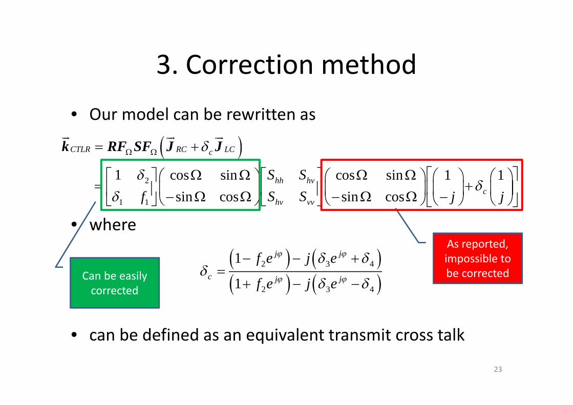
• Our model can be rewritten as
• where
• can be defined as an equivalent transmit cross talk
( )2
1 1
1 cos sin cos sin 1 1
sin cos sin cos
CTLR RC LCc
hh hvc
hv vv
S S
S Sf j j
d
dd
d
W W= +
W W W W é ùé ùé ù æ ö æ ö æ ö æ ö= +ê úç ÷ ç ÷ ç ÷ ç ÷ê úê ú - W W - W W -è ø è ø è ø è øë û ë û ë û
ur ur urk RF SF J J
( ) ( )( ) ( )
2 3 4
2 3 4
1
1
j j
c j j
f e j e
f e j e
j j
j j
d dd
d d
- - +=
+ - -
As reported, impossible to be correctedCan be easily
corrected
23
3. Correction method
To remove the cross talk and the Faraday rotation effect in transmit, we propose a correction method [4].
[4] Hong Tan, Jun Hong. Correction of transmit crosstalk in reconstruction of quad-pol data from compact polarimetry data[J], IEEE Geosci. Remote Sens. Lett., 12(5): 1051-1055, 2015.
24
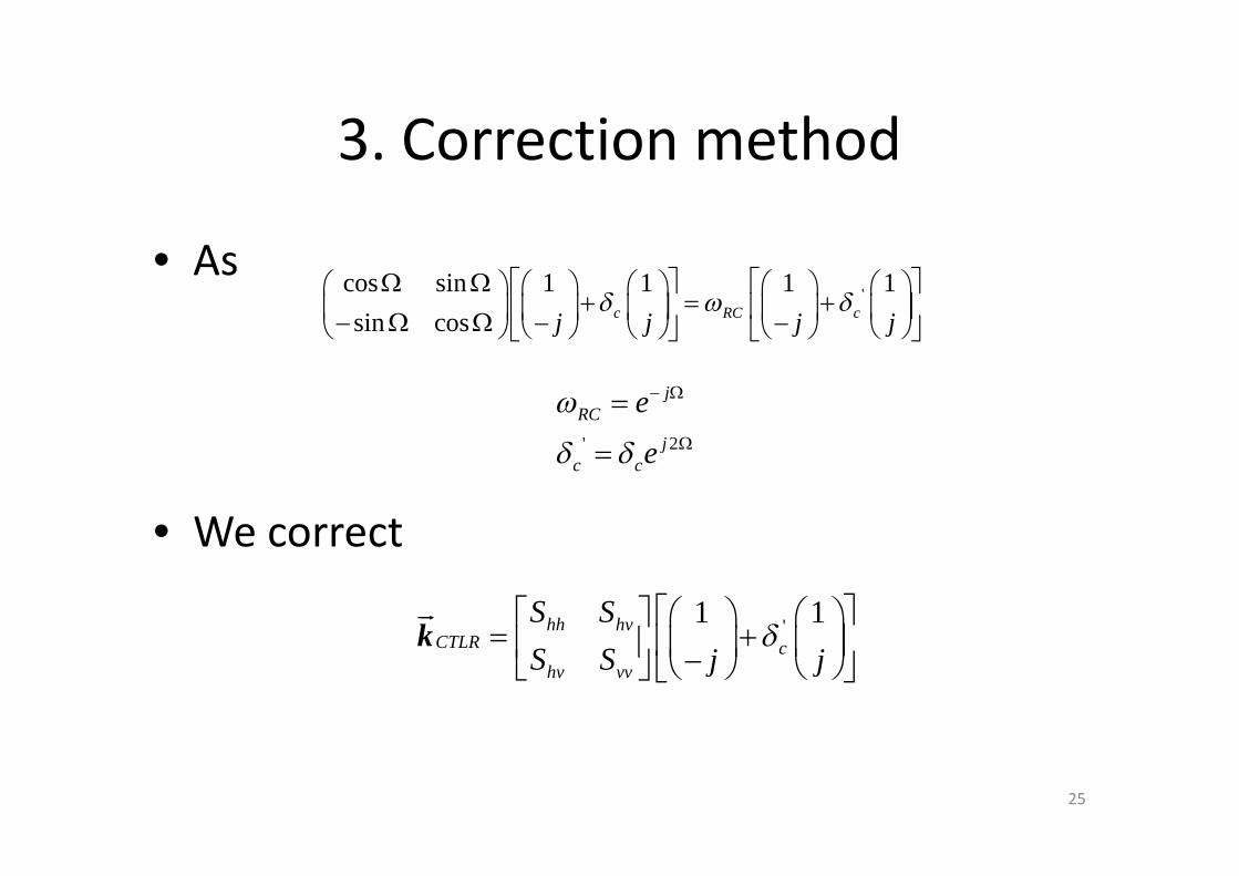
3. Correction method
• As
• We correct
'cos sin 1 1 1 1
sin cos c RC cj j j jd w d
W W é ù é ùæ ö æ ö æ ö æ ö æ ö+ = +ê ú ê úç ÷ ç ÷ ç ÷ ç ÷ ç ÷- W W - -è ø è ø è ø è ø è øë û ë û
' 2
jRC
jc c
e
e
w
d d
- W
W
=
=
'1 1hh hvCTLR c
hv vv
S S
S S j jd
é ùé ù æ ö æ ö= +ê úç ÷ ç ÷ê ú -è ø è øë û ë û
urk
25
3. Correction method
• It is true that the transmit cross talk can not be corrected to get the real scattering vector.
• But when reconstructing pseudo quad-polarimetric information in the form of covariance matrix instead of the scattering vector, it is possible.
26

3. Correction method
• An iterative method similar to Souyris’s [5] reconstruction method is derived
• With a similar assumption– Most natural distributed targets respect the
reflection symmetry
[5] J. C. Souyris, P. Imbo, R. Fjørtoft, et al. Compact polarimetry based on symmetry properties of geophysical media: The pi/4 mode[J], IEEE Trans. Geosci. Remote Sens. 2005, 43(3): 634-646.
27
3. Correction method
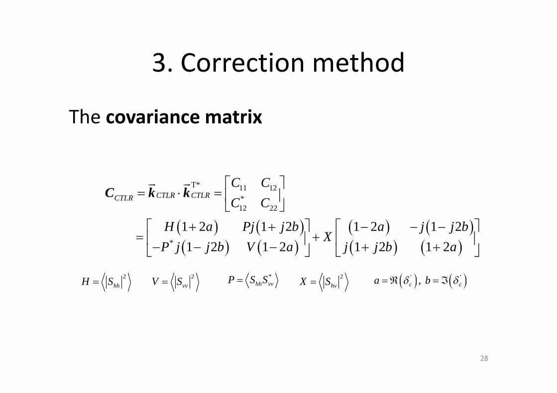
The covariance matrix
( ) ( )( ) ( )
( ) ( )( ) ( )
T* 11 12*12 22
*
1 2 1 2 1 2 1 2
1 2 1 2 1 2 1 2
CTLR CTLRCTLR
C C
C C
H a Pj j b a j j bX
P j j b V a j j b a
é ù= × = ê ú
ë û+ + - - -é ù é ù
= +ê ú ê ú- - - + +ë û ë û
ur urC k k
( ) ( )' ', c ca bd d= Â = Á2
hhH S= 2
vvV S=*
hh vvP S S= 2
hvX S=
28
3. Correction method
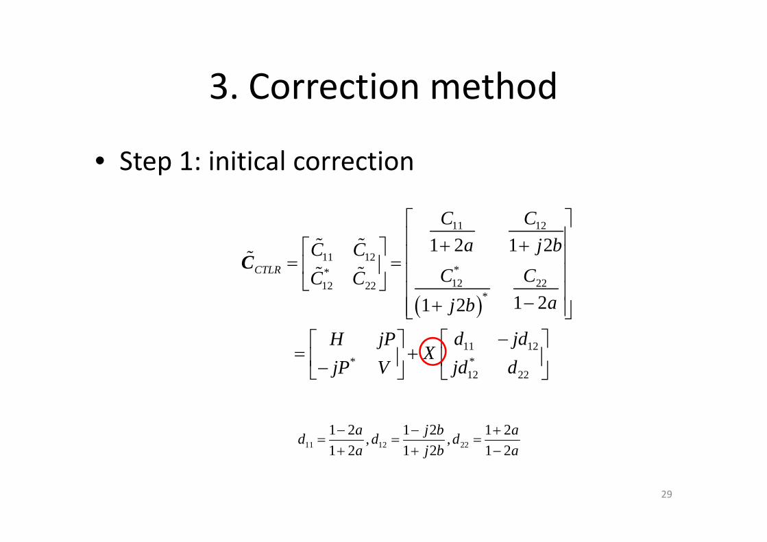
• Step 1: initical correction
( )
11 12
11 12**12 2212 22
*
11 12**12 22
1 2 1 2
1 21 2
CTLR
C Ca j bC C
C CC Caj b
d jdH jPX
jd djP V
é ùê ú+ +é ù ê ú= =ê ú ê úë û ê ú-+ê úë û
-é ùé ù= + ê úê ú-ë û ë û
C% %% % %
11 12 22
1 2 1 2 1 2, ,
1 2 1 2 1 2a j b a
d d da j b a
- - += = =
+ + -
29

3. Correction method
• Step 2: iterative algorithm to estimate X– Start with X=0
– Iterate until X converge
12(0)
11 22
jC
C Cr -
=%
% %
( )( )( )( )11 22 (0)
(0)
11 22 (0)
1
1
C CX
N d d
r
r
+ -=
+ + -
% %
( )( )12 ( ) 12
( 1)
11 ( ) 11 22 ( ) 22
ii
i i
jC X d
C X d C X dr +
- +=
- -
%% %
( )( )( )( )11 22 ( 1)
( 1)
11 22 ( 1)
1
1
i
i
i
C CX
N d d
r
r
+
+
+
+ -=
+ + -
% %
30
3. Correction method
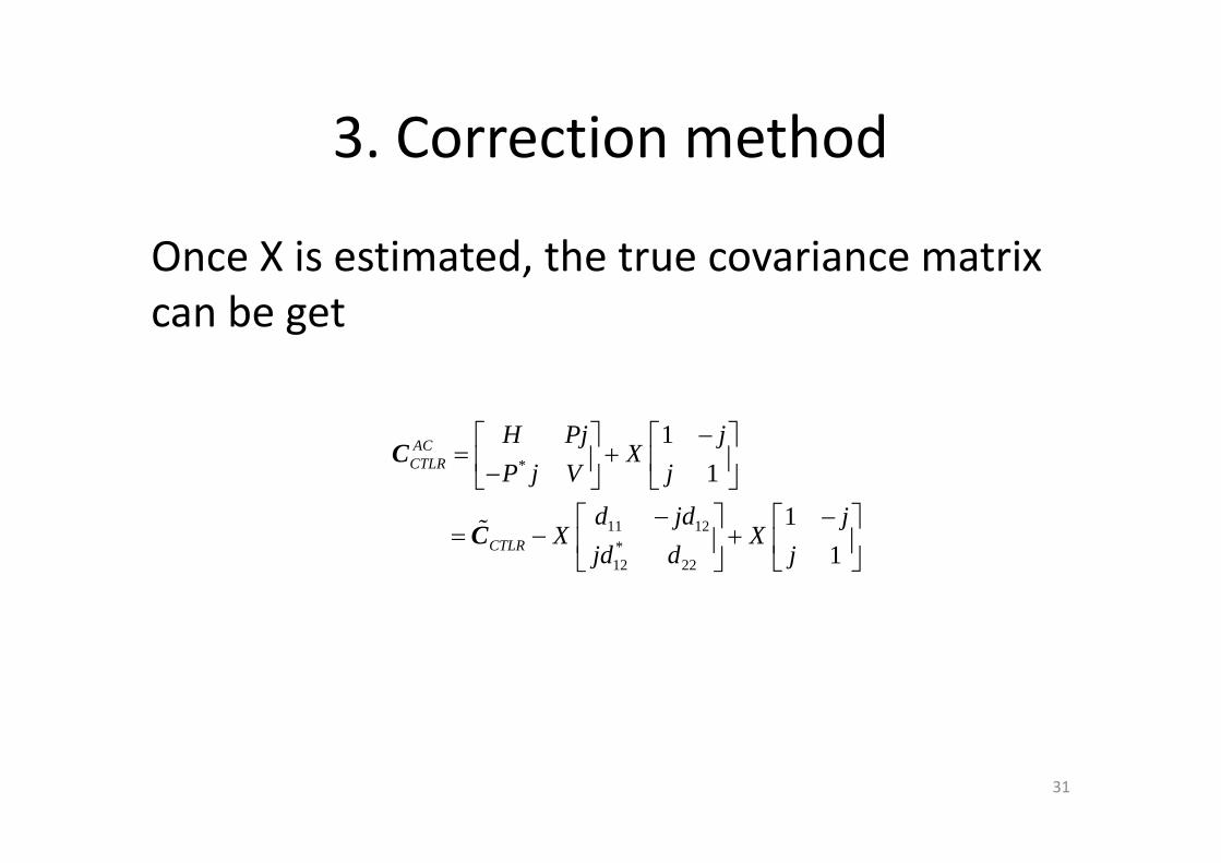
Once X is estimated, the true covariance matrix can be get
*
11 12*12 22
1
1
1
1
ACCTLR
CTLR
H Pj jX
P j V j
d jd jX X
jd d j
-é ù é ù= +ê ú ê ú-ë û ë û
- -é ù é ù= - +ê ú ê ú
ë ûë û
C
C%
31
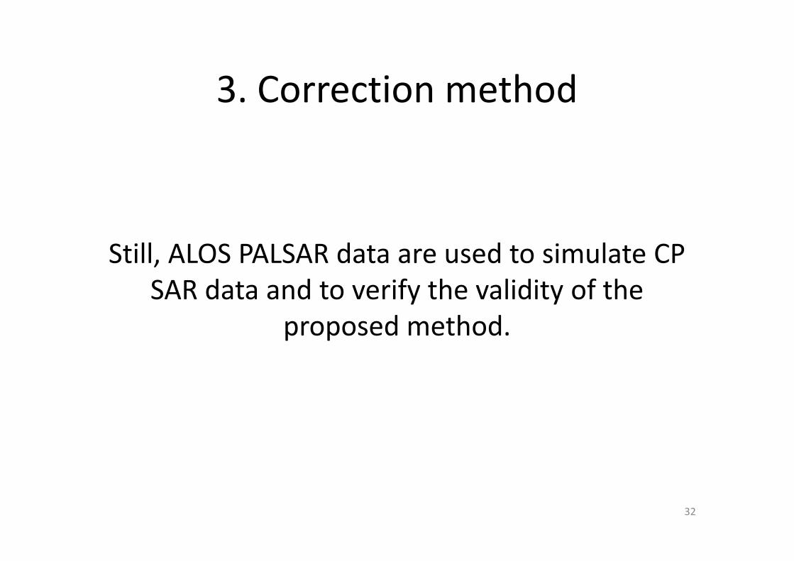
3. Correction method
Still, ALOS PALSAR data are used to simulate CP SAR data and to verify the validity of the
proposed method.
32

3. Correction method
-35 -30 -25 -20 -15 -10 -5-60
-40
-20
0
|dc| (dB)
Rel
ativ
e E
rror
in H
(%
)
-35 -30 -25 -20 -15 -10 -5
-20
0
20
40
|dc| (dB)
Rel
ativ
e E
rror
in V
(%
)
-35 -30 -25 -20 -15 -10 -5
-20
-10
0
|dc| (dB)
Rel
ativ
e E
rror
in X
(%
)
BC
AC
2
hhS
2
hvS
2
vvS
BC: before correction, AC: after correction
-35 -30 -25 -20 -15 -10 -5-0.1
-0.05
0
|dc| (dB)
Err
or in
| r|
-35 -30 -25 -20 -15 -10 -5-10
-5
0
5
10
15
|dc| (dB)
Err
or in
Pha
se( r
) (d
eg)
BC
AC
*
2 2
hh vv
hh vv
S S
S Sr º
33
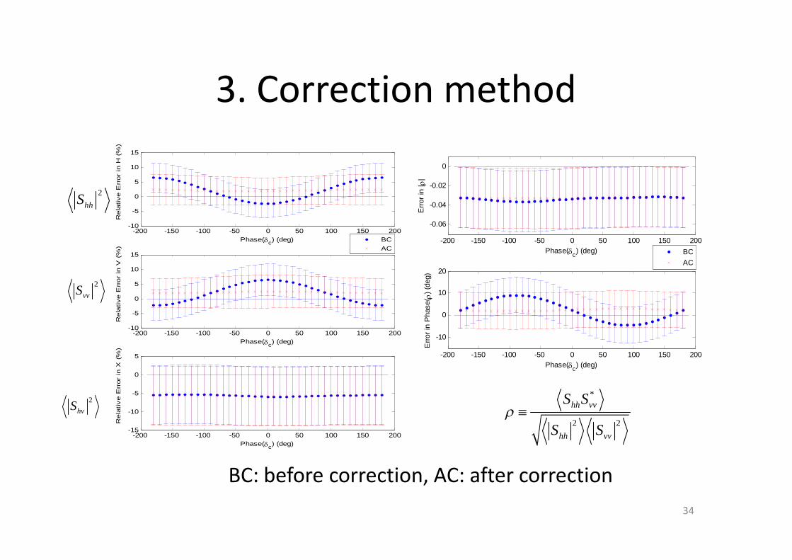
3. Correction method
-200 -150 -100 -50 0 50 100 150 200-10
-5
0
5
10
15
Phase(dc) (deg)
Rela
tive E
rror
in H
(%
)
-200 -150 -100 -50 0 50 100 150 200-10
-5
0
5
10
15
Phase(dc) (deg)
Rela
tive E
rror
in V
(%
)
-200 -150 -100 -50 0 50 100 150 200-15
-10
-5
0
5
Phase(dc) (deg)
Rela
tive E
rror
in X
(%
)
BC
AC
BC: before correction, AC: after correction
-200 -150 -100 -50 0 50 100 150 200
-0.06
-0.04
-0.02
0
Phase(dc) (deg)
Err
or in
| r|
-200 -150 -100 -50 0 50 100 150 200
-10
0
10
20
Phase(dc) (deg)
Err
or in
Pha
se( r
) (d
eg)
BC
AC
2
hhS
2
vvS
2
hvS*
2 2
hh vv
hh vv
S S
S Sr º
34

3. Correction method
The proposed algorithm performs effectively and stably under certain
conditions for any transmit crosstalk amplitude no larger than -15dB.
35

Thanks!
Q & A
36