Embed Size (px)
Citation preview
Calibration of Hall Probes at Cryogenic Temperatures
M. Abliz, I.B.Vasserman, C. Doose, E.M. Trakhtenberg,
Y. Ivanyushenkov, J. Xu
Argonne National Laboratory
The 16th Pan-American Synchrotron Radiation Instrumentation Conference September 21-24, 2010
@ Argonne National Laboratory, USA
Workshop 3: Superconducting undulators and other new ID sources
@
M. Abliz, The 16th Pan-American Synchrotron Radiation Instrumentation
2
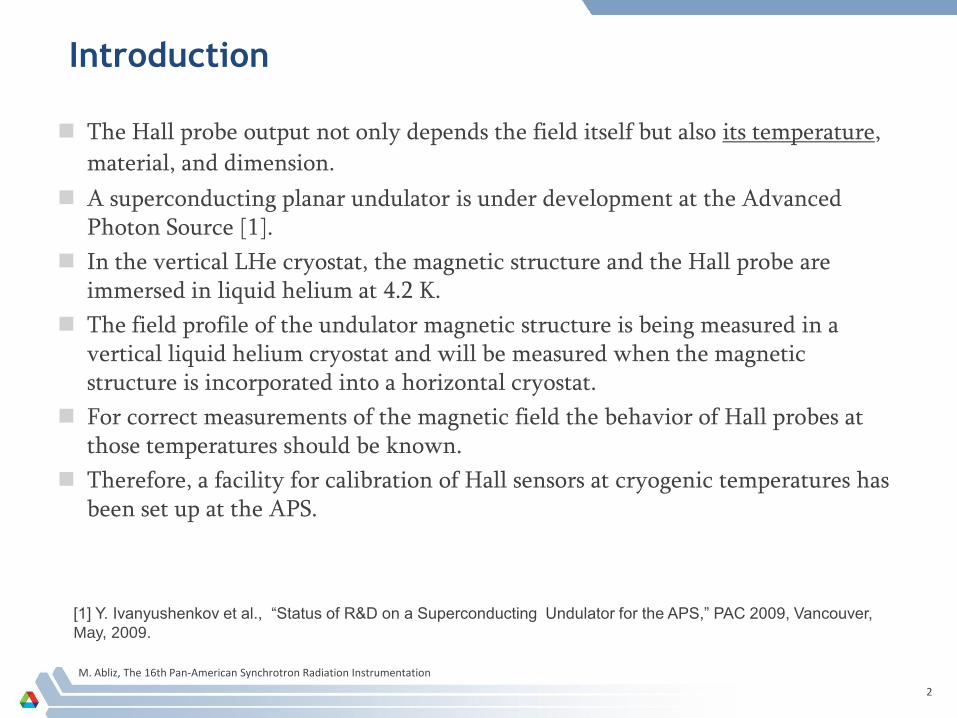
Introduction
The Hall probe output not only depends the field itself but also its temperature,
material, and dimension.
A superconducting planar undulator is under development at the Advanced Photon Source [1].
In the vertical LHe cryostat, the magnetic structure and the Hall probe are immersed in liquid helium at 4.2 K.
The field profile of the undulator magnetic structure is being measured in a vertical liquid helium cryostat and will be measured when the magnetic structure is incorporated into a horizontal cryostat.
For correct measurements of the magnetic field the behavior of Hall probes at those temperatures should be known.
Therefore, a facility for calibration of Hall sensors at cryogenic temperatures has been set up at the APS.
[1] Y. Ivanyushenkov et al., “Status of R&D on a Superconducting Undulator for the APS,” PAC 2009, Vancouver,
May, 2009.
M. Abliz, The 16th Pan-American Synchrotron Radiation Instrumentation
3
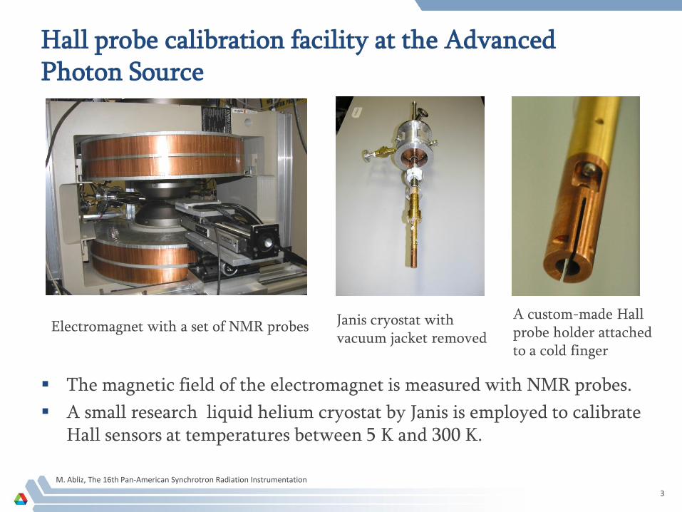
Hall probe calibration facility at the Advanced Photon Source
The magnetic field of the electromagnet is measured with NMR probes.
A small research liquid helium cryostat by Janis is employed to calibrate Hall sensors at temperatures between 5 K and 300 K.
Electromagnet with a set of NMR probes Janis cryostat with vacuum jacket removed
A custom-made Hall probe holder attached to a cold finger
M. Abliz, The 16th Pan-American Synchrotron Radiation Instrumentation
4
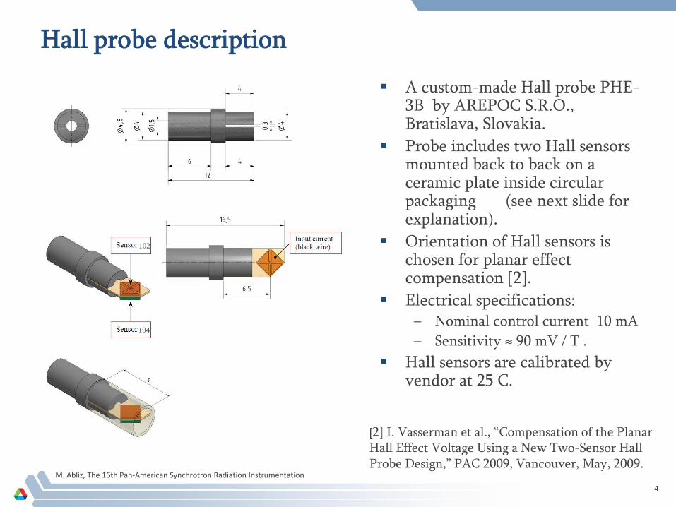
Hall probe description
A custom-made Hall probe PHE-3B by AREPOC S.R.O., Bratislava, Slovakia.
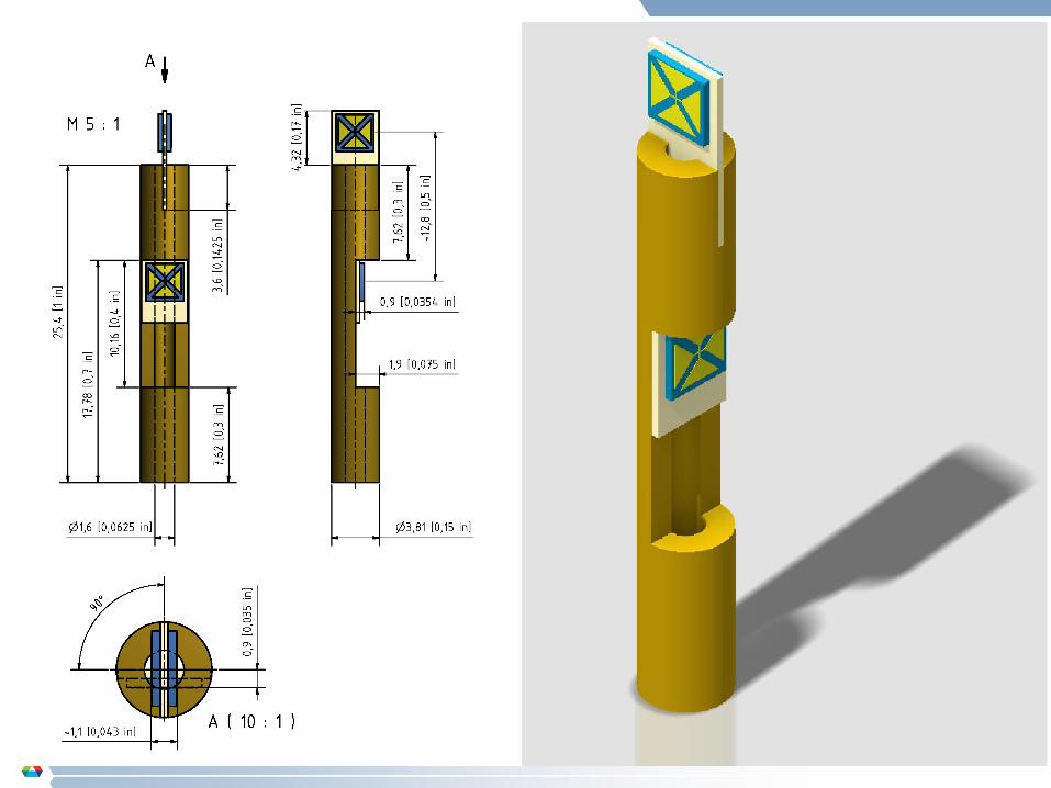
Probe includes two Hall sensors mounted back to back on a ceramic plate inside circular packaging (see next slide for explanation).
Orientation of Hall sensors is chosen for planar effect compensation [2].
Electrical specifications:– Nominal control current 10 mA
– Sensitivity ≈ 90 mV / T .
Hall sensors are calibrated by vendor at 25 C.
[2] I. Vasserman et al., “Compensation of the Planar Hall Effect Voltage Using a New Two-Sensor Hall Probe Design,” PAC 2009, Vancouver, May, 2009.
102
104
M. Abliz, The 16th Pan-American Synchrotron Radiation Instrumentation
5
M. Abliz, The 16th Pan-American Synchrotron Radiation Instrumentation
6
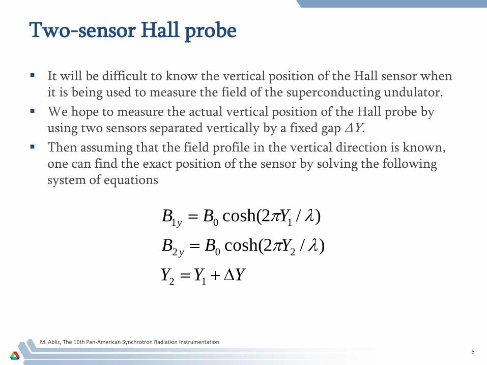
Two-sensor Hall probe
It will be difficult to know the vertical position of the Hall sensor when it is being used to measure the field of the superconducting undulator.
We hope to measure the actual vertical position of the Hall probe by using two sensors separated vertically by a fixed gap ΔY.
Then assuming that the field profile in the vertical direction is known, one can find the exact position of the sensor by solving the following system of equations
YYY
YBB
YBB
y
y
12
202
101
)/2cosh(
)/2cosh(
M. Abliz, The 16th Pan-American Synchrotron Radiation Instrumentation
7
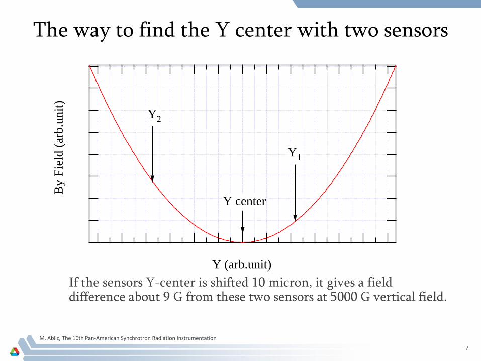
The way to find the Y center with two sensors
If the sensors Y-center is shifted 10 micron, it gives a field difference about 9 G from these two sensors at 5000 G vertical field.
By F
ield
(ar
b.u
nit
)
Y (arb.unit)
Y center
Y1
Y2
M. Abliz, The 16th Pan-American Synchrotron Radiation Instrumentation
8
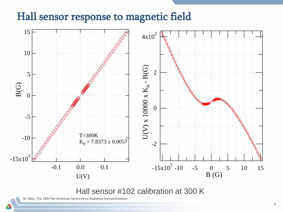
Calibration of Hall probe sensors
The magnetic field Bmes=f(V) from Hall probe voltage measurements can
be written as : Bmes=k(V)V, where Bmes is the magnetic field measured
with Hall sensor, V is the voltage of Hall sensor, and k(V) is a nonlinear
coefficient:
k(V)=k0 + k1 V+ k2 V2 + k3 V3 + ...
A linear fit with least square method of Bmes=k(V)V determines k0 , Bmes≈ k0V, where k0 is the linear part of the coefficient called Hall probe
sensitivity.
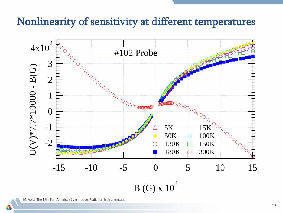
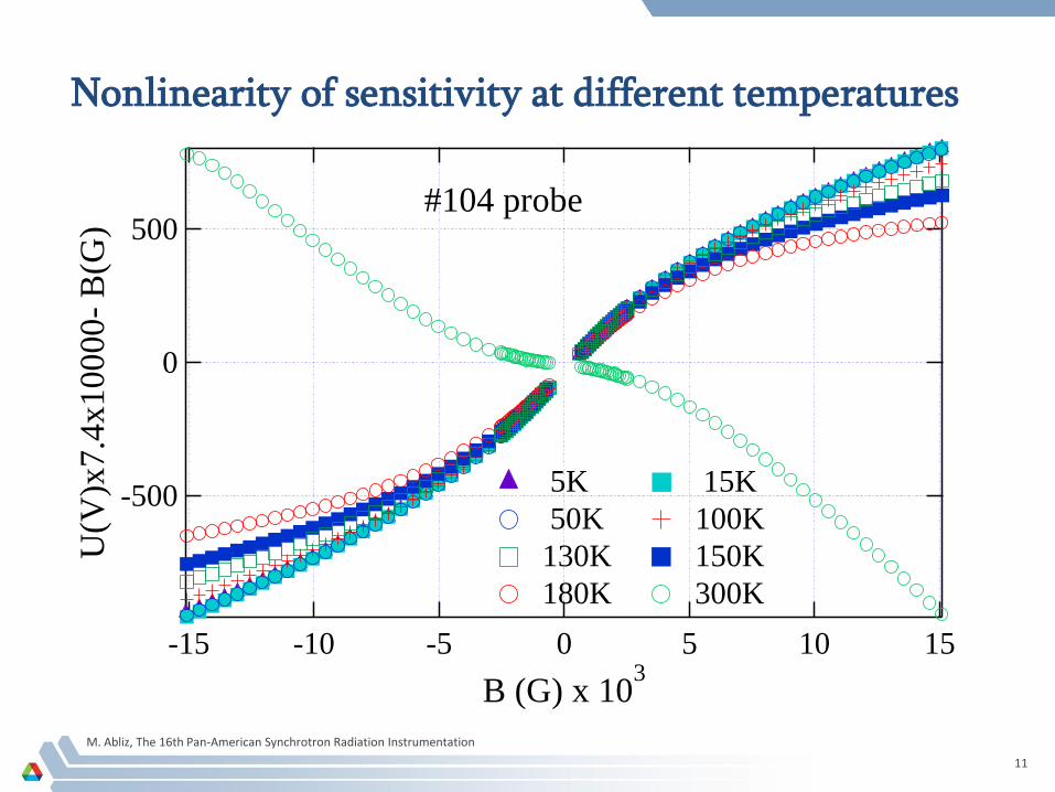
Then the difference of k0V - Bref as a function of Bref shows the
nonlinearity of the probe, where magnetic field Bref is measured with a
reference NMR probe
Our goal was to measure dependence of Hall probe calibration
coefficient on the temperature
M. Abliz, The 16th Pan-American Synchrotron Radiation Instrumentation
9
Hall sensor response to magnetic field
Hall sensor #102 calibration at 300 K
-15x103
-10
-5
0
5
10
15
B(G
)
0.10.0-0.1
U(V)
T=300K K0 = 7.8373 ± 0.0057
4x10²
2
0
-2U
(V)
x 1
00
00
x K
0 -
B(G
)
-15x103
-10 -5 0 5 10 15B (G)
M. Abliz, The 16th Pan-American Synchrotron Radiation Instrumentation
10
Nonlinearity of sensitivity at different temperatures
4x10²
3
2
1
0
-1
-2
U(V
)*7
.7*
10
00
0 -
B(G
)
-15 -10 -5 0 5 10 15
B (G) x 103
5K 15K 50K 100K 130K 150K 180K 300K
#102 Probe
M. Abliz, The 16th Pan-American Synchrotron Radiation Instrumentation
11
Nonlinearity of sensitivity at different temperatures
-500
0
500
U(V
)x7
.4x
10
00
0-
B(G
)
151050-5-10-15
B (G) x 103
5K 15K
50K 100K
130K 150K
180K 300K
#104 probe
M. Abliz, The 16th Pan-American Synchrotron Radiation Instrumentation
12
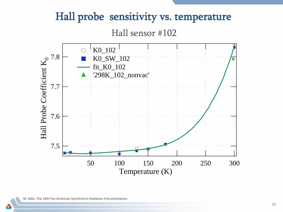
Hall probe sensitivity vs. temperature
Hall sensor #102
7.8
7.7
7.6
7.5
Hal
l P
rob
e C
oef
fici
ent
K0
30025020015010050
Temperature (K)
K0_102
K0_SW_102
fit_K0_102 '298K_102_nonvac'
M. Abliz, The 16th Pan-American Synchrotron Radiation Instrumentation
13
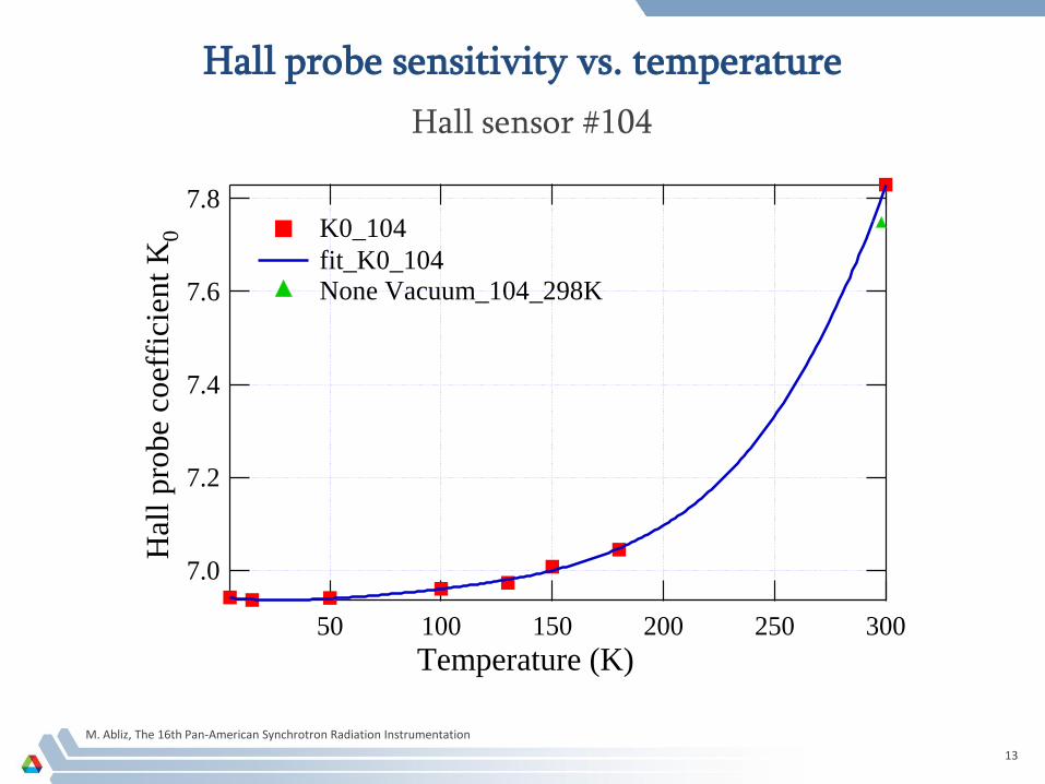
Hall probe sensitivity vs. temperature
Hall sensor #104
7.8
7.6
7.4
7.2
7.0
Hal
l pro
be
coef
fici
ent
K0
30025020015010050
Temperature (K)
K0_104
fit_K0_104 None Vacuum_104_298K
M. Abliz, The 16th Pan-American Synchrotron Radiation Instrumentation
14
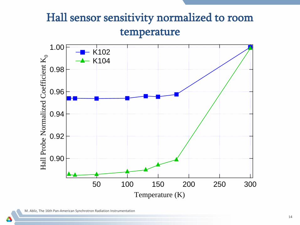
Hall sensor sensitivity normalized to room temperature
1.00
0.98
0.96
0.94
0.92
0.90
Hal
l P
robe
Norm
aliz
ed C
oef
fici
ent
K0
30025020015010050
Temperature (K)
K102 K104
M. Abliz, The 16th Pan-American Synchrotron Radiation Instrumentation
15
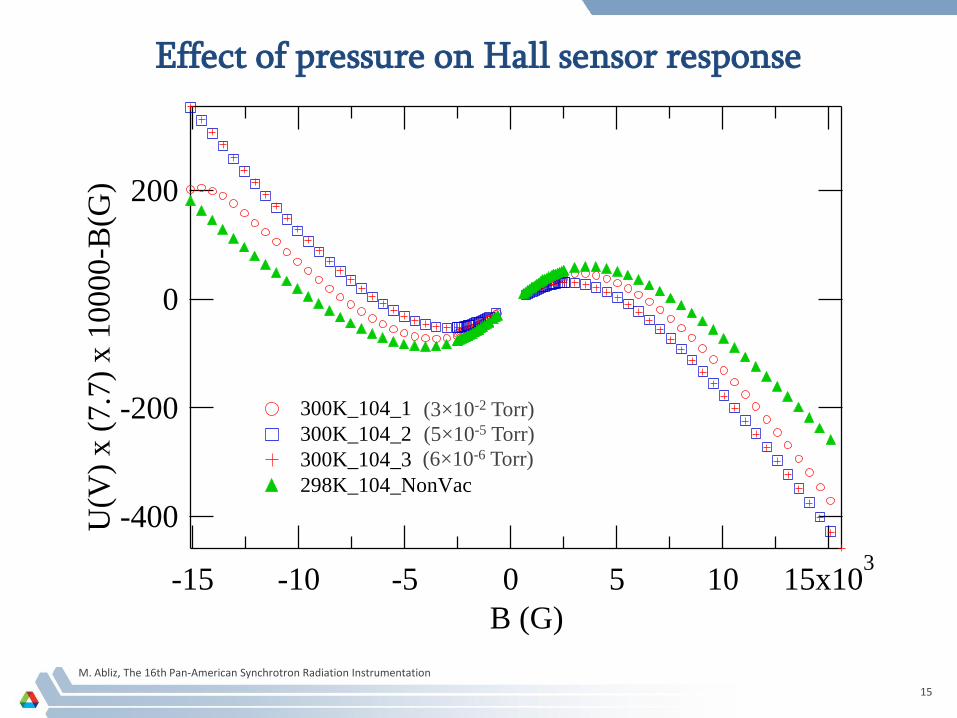
Effect of pressure on Hall sensor response
-400
-200
0
200
U(V
) x (
7.7
) x 1
0000-B
(G)
15x103
1050-5-10-15
B (G)
300K_104_1
300K_104_2
300K_104_3
298K_104_NonVac
(3×10⁻² Torr)
(5×10⁻⁵ Torr)
(6×10⁻⁶ Torr)

M. Abliz, The 16th Pan-American Synchrotron Radiation Instrumentation
16
Results and discussion
Two Hall sensors (both are in the same probe package) were calibrated at temperatures between 5 K and 300 K.
The sensitivity increases by about 4.5 % for one sensor and by almost 12 % for the other when the temperature is decreased from 300 K to 5 K.
The Hall probe sensitivity increases quickly between 300 K and about 150 K and then is constant between 50 K and 5 K.
At room temperature, the Hall probe response is sensitive to the pressure in the cryostat.
M. Abliz, The 16th Pan-American Synchrotron Radiation Instrumentation
17
Conclusion
A facility for Hall probe calibration at cryogenic temperatures is now in operation at the Advanced Photon Source.
The Hall probe sensitivity is strongly temperature dependent between 300 K and 150 K, changing by up to 12 %.
The Hall probe sensitivity is nearly temperature independent below 50 K.
The Hall probe sensitivity varies with the level of vacuum in the cryostat.
We will continue systematic studies of behavior of Hall sensors of different types at cryogenic temperatures.
M. Abliz, The 16th Pan-American Synchrotron Radiation Instrumentation
18
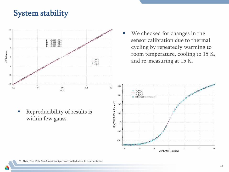
System stability
Reproducibility of results is within few gauss.
We checked for changes in the sensor calibration due to thermal cycling by repeatedly warming to room temperature, cooling to 15 K, and re-measuring at 15 K.


![CASH VALVE CRYOGENIC CONTROLS - CMC Technologies Pty … · 2017. 5. 10. · cryogenic temperatures in a Dewar with the same measured volume of one cubic foot [0.028 cubic meter]](https://img.pdfslide.net/doc/110x75/5fdea2f647097a1203410490/cash-valve-cryogenic-controls-cmc-technologies-pty-2017-5-10-cryogenic-temperatures.jpg)