Embed Size (px)
Citation preview
5
Calibration of Robot Reference Frames for Enhanced Robot Positioning Accuracy
Frank Shaopeng Cheng Central Michigan University
United States
1. Introduction
Industrial robot manipulators are important components of most automated manufacturing systems. Their design and applications rely on modeling, analyzing, and programming the robot tool-center-point (TCP) positions with the best accuracy. Industrial practice shows that creating accurate robot TCP positions for robot applications such as welding, material handling, and inspection is a critical task that can be very time-consuming depending on the complexity of robot operations. Many factors may affect the accuracy of created robot TCP positions. Among them, variations of robot geometric parameters such as robot link dimensions and joint orientations represent the major cause of overall robot positioning errors. This is because the robot kinematic model uses robot geometric parameters to determine robot TCP position and corresponding joint values in the robot system. In addition, positioning variations of the robots and their end-effectors also affect the accuracy of robot TCP positions in a robot work environment. Model-based robot calibration is an integrated solution that has been developed and applied to improve robot positioning accuracy through software rather than changing the mechanical structure or design of the robot itself. The calibration technology involves four steps: modeling the robot mechanism, measuring strategically planned robot TCP positions, identifying true robot frame parameters, and compensating existing robot TCP positions for the best accuracy. Today, commercial robot calibration systems play an increasingly important role in industrial robot applications because they are able to minimize the risk of having to manually recreate required robot TCP positions for robot programs after the robots, end-effectors, and fixtures are slightly changed in robot workcells. Due to the significant reduction of robot production downtime, this practice is extremely beneficial to robot applications that may involve a rather large number of robot TCP positions. This chapter provides readers with methods of calibrating the positions of robot reference frames for enhancing robot positioning accuracy in industrial robot applications. It is organized in the following sections: Section 2 introduces basic concepts and methods used in modeling static positions of an industrial robot. This includes robot reference frames, joint parameters, frame transformations, and robot kinematics. Section 3 discusses methods and techniques for identifying the true parameters of robot reference frames. Section 4 presents applications of robot calibration methods in transferring existing robot programs among
www.intechopen.com
Robot Manipulators
96
“identical” robot workcells. Section 5 describes calibration procedures for conducting true robotic simulation and offline programming. Finally, conclusions are given in Section 6.
2. Robot Reference Frames and Frame Transformations
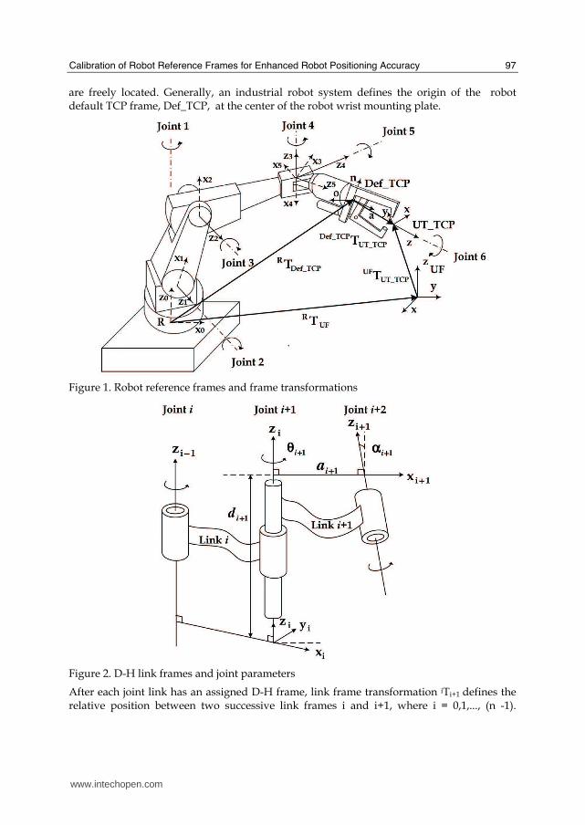
An industrial robot is a multiple degrees-of-freedom (DOF) manipulator built with a series of mechanical joints. The static positions of the robot are represented by Cartesian reference frames and frame transformations as shown in Fig 1. The robot world reference frame, R (x, y, z), is a fixed one in the robot world space and the robot default tool-center-point (TCP)
frame, Def_TCP (n, o, a), is a moving one representing the robot end-point. The 4 × 4 homogeneous transformation matrix in Eq. (1) mathematically represents the position of default TCP frame Def_TCP relative to robot base frame R:
⎥⎥⎥⎥⎥
⎦
⎤
⎢⎢⎢⎢⎢
⎣
⎡=
1000
paon
paon
paon
Tzzzz
yyyy
xxxx
TCP_DefR , (1)
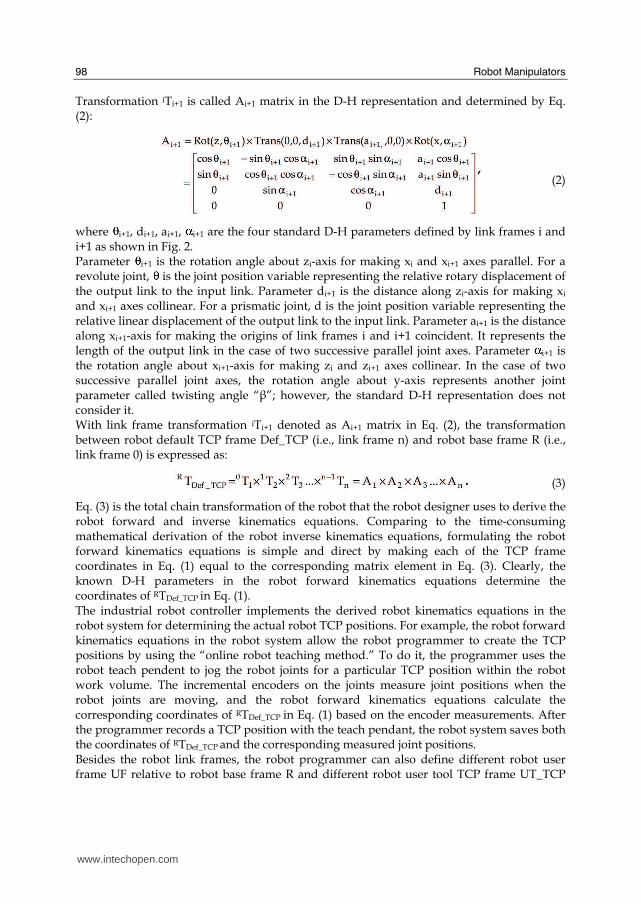
where the coordinates of point vector p represent TCP frame location and the coordinates of three unit directional vectors [n, o, a] of the frame represent TCP frame orientation. The arrow from robot base frame R to default TCP frame Def_TCP graphically represents transformation matrix RTDef_TCP as shown in Fig. 1. The inverse of RTDef_TCP denoted as (RTDef_TCP)-1 represents the position of robot base frame R measured relative to default TCP frame Def_TCP denoted as Def_TCPTR. Generally, the definition of a frame transformation matrix or its inverse as described with the examples of RTDef_TCP and (RTDef_TCP)-1 can be applied to any available reference frame in the robot system. A robot joint consists of an input link and an output link. The relative position between the input and output links defines the joint position. It is obvious that different robot joint positions result in different robot TCP frame positions. Mathematically, robot kinematics called robot kinematic model describes the geometric motion relationship between a given robot TCP frame position expressed in Eq. (1) and corresponding robot joint positions. Specifically, robot forward kinematics will enable the robot system to determine where the TCP frame position will be if all the joint positions are known. Robot inverse kinematics will enable the robot system to calculate what each joint position must be if the robot TCP frame is desired to be at a particular position. Developing robot kinematics equations starts with the use of Cartesian reference frames for representing the relative position between two successive robot links as shown in Fig. 1. The Denavit-Hartenberg (D-H) representation is an effective way of systematically modeling the link positions of robot joints, regardless of their sequences or complexities (Denavit & Hartenberg, 1955). It allows the robot designer to assign the link frames of a robot joint with the following rules as shown in Fig. 2. The z-axis of the input-link frame is always along the joint axis with arbitrary directions. The x-axis of the output-link frame must be perpendicular and intersecting to the z-axis of the input-link frame of the joint. The y-axis of a link frame follows the right hand rule of the Cartesian frame. For an n-joint robot, frame 0 on the first link (i.e., link 0) serves as robot base frame R and frame n on the last link (i.e., link n) serves as robot default TCP frame Def_TCP. The origins of frames R and Def_TCP
www.intechopen.com
Calibration of Robot Reference Frames for Enhanced Robot Positioning Accuracy
97
are freely located. Generally, an industrial robot system defines the origin of the robot default TCP frame, Def_TCP, at the center of the robot wrist mounting plate.
Figure 1. Robot reference frames and frame transformations
Figure 2. D-H link frames and joint parameters
After each joint link has an assigned D-H frame, link frame transformation iTi+1 defines the relative position between two successive link frames i and i+1, where i = 0,1,..., (n -1).
www.intechopen.com
Robot Manipulators
98
Transformation iTi+1 is called Ai+1 matrix in the D-H representation and determined by Eq. (2):
(2)
where i+1, di+1, ai+1, i+1 are the four standard D-H parameters defined by link frames i and i+1 as shown in Fig. 2. Parameter i+1 is the rotation angle about zi-axis for making xi and xi+1 axes parallel. For a revolute joint, is the joint position variable representing the relative rotary displacement of the output link to the input link. Parameter di+1 is the distance along zi-axis for making xi and xi+1 axes collinear. For a prismatic joint, d is the joint position variable representing the relative linear displacement of the output link to the input link. Parameter ai+1 is the distance along xi+1-axis for making the origins of link frames i and i+1 coincident. It represents the length of the output link in the case of two successive parallel joint axes. Parameter i+1 is the rotation angle about xi+1-axis for making zi and zi+1 axes collinear. In the case of two successive parallel joint axes, the rotation angle about y-axis represents another joint parameter called twisting angle “β”; however, the standard D-H representation does not consider it. With link frame transformation iTi+1 denoted as Ai+1 matrix in Eq. (2), the transformation between robot default TCP frame Def_TCP (i.e., link frame n) and robot base frame R (i.e., link frame 0) is expressed as:
(3)
Eq. (3) is the total chain transformation of the robot that the robot designer uses to derive the robot forward and inverse kinematics equations. Comparing to the time-consuming mathematical derivation of the robot inverse kinematics equations, formulating the robot forward kinematics equations is simple and direct by making each of the TCP frame coordinates in Eq. (1) equal to the corresponding matrix element in Eq. (3). Clearly, the known D-H parameters in the robot forward kinematics equations determine the coordinates of RTDef_TCP in Eq. (1). The industrial robot controller implements the derived robot kinematics equations in the robot system for determining the actual robot TCP positions. For example, the robot forward kinematics equations in the robot system allow the robot programmer to create the TCP positions by using the “online robot teaching method.” To do it, the programmer uses the robot teach pendent to jog the robot joints for a particular TCP position within the robot work volume. The incremental encoders on the joints measure joint positions when the robot joints are moving, and the robot forward kinematics equations calculate the corresponding coordinates of RTDef_TCP in Eq. (1) based on the encoder measurements. After the programmer records a TCP position with the teach pendant, the robot system saves both the coordinates of RTDef_TCP and the corresponding measured joint positions. Besides the robot link frames, the robot programmer can also define different robot user frame UF relative to robot base frame R and different robot user tool TCP frame UT_TCP
www.intechopen.com
Calibration of Robot Reference Frames for Enhanced Robot Positioning Accuracy
99
relative to the default TCP frame. They are denoted as transformations RTUF and Def_TCPTUT_TCP as shown in Fig. 1, respectively. After a user frame and a user tool frame are established and set active in the robot system, Eq. (4) determines the coordinates of the actual robot TCP position, UFTUT_TCP , as shown in Fig. 1:
(4)
3. Calibration of Robot Reference Frames
Eq. (4) shows that an industrial robot is an open-loop, multiple degrees-of-freedom (DOF) mechanism modeled by a series of frame transformations. If any frame transformation in Eq. (4) is different from the corresponding one used by the actual robot system, the actual robot TCP positions are to be different from those calculated by the robot kinematics equations in the robot system, which results in robot TCP position errors. This section introduces robot calibration methods and techniques for enhancing robot positioning accuracy.
3.1 Calibration of Robot Link Frames
The nominal values of the D-H parameters used in Eq. (3) are often different from the corresponding ones of the actual robot system, causing robot TCP position errors of an existing or new industrial robot from about 5 mm to 15 mm (Motta, et al., 2001). The variations of robot D-H parameters are the result of both the geometric effects such as link tolerance and link twist and the non-geometric effects including joint compliance, link flexibility, gravity loading, joint backlash, gear train harmonics, controller steady state error, and temperature variation (Roth et al., 1987 and Greenway, 2000). For a well-built robot operated within its load and speed limitations, the geometric effects represent approximately 90 percent of the overall robot TCP position errors (Bernhardt, 1997 and Schroer, 1993). In this sense, every industrial robot has its own “true geometric parameters” and the calculated robot TCP positions are not accurate if the robot kinematic model does not use the true robot parameters. One important concern about the robot TCP position error is the variations of the “zero” position values of the robot joint variables. As mentioned in Section 2, most industrial robot systems use incremental encoders to measure robot joint positions. Because an incremental encoder is not able to measure the absolute joint position without a defined “zero” joint position value, the robot programmer must calibrate the “zero” values of the robot encoders by performing the robot “mastering” procedure. During the “mastering” process, the programmer manually jogs each robot joint to a position within the joint travel limit and then set the corresponding joint encoder value to “zero” in the robot system. As long as the defined “zero” values of the joints and the corresponding joint encoders remain unchanged, the recorded robot TCP positions are accurate via the actual encoder measurements. But the programmer must calibrate the robot system each time when any of the actual encoders looses the pre-defined “zero” value in the robot system. This may occur due to either replacing the broken joint motor and encoder, or accidentally losing the battery support to all actual robot encoders after the robot power-off. However, performing the robot “mastering” procedure usually results in different “zero” joint positions for the joint encoders. Consequently, all pre-recorded robot TCP positions are no longer accurate for the originally programmed robot operations simply because for a given robot joint position
www.intechopen.com
Robot Manipulators
100
(e.g., 30 degrees) the actual position of the joint output link can be completely different depending on the actual defined “zero” joint position in the system. To reuse the pr-recorded robot TCP positions in the robot operations after losing the robot “zero” joint positions, the robot programmer needs to precisely recover these values by identifying the true robot parameters. Researchers have investigated the problems and methods of calibrating the robot parameters for many years. Most works have been focused on the kinematic model-based calibration that is considered a global calibration method of enhancing the robot positioning accuracy across the robot work volume. Because of the physical explicit significance of the D-H model and its widespread use in the industrial robot control software, identification methods have been developed to directly obtain the true robot D-H parameters and the additional twist angle “ ” in the case of consecutive parallel joint axes (Stone, 1987,
Abderrahim & Whittaker, 2000). To better understand the process of robot parameter identification, assume that p = [p1T... pnT]T is the parameter vector for an n-joint robot, and pi+1 is the link parameter vector for joint i+1. Then, the actual link frame transformation iAi+1 in Eq. (2) can be expressed as (Driels & Pathre, 1990):
(5)
where pi+1 is the link parameter error vector for joint i+1. Thus, the exact actual robot chain transformation in Eq. (3) is:
(6)
where p = [ p1T p2T ... pnT]T is the robot parameter error vector and q = [q1, q2, ... qn]T is
the vector of robot joint position variables. Studies show that in Eq. (6) is a non-linear function of robot parameter error vector p. For identifying the true robot parameters, an external measuring system must be used to measure a number of strategically planned robot
TCP positions. Then, an identification algorithm computes parameter values p* = p + Δp that result in an optimal fit between the actually measured TCP positions and those computed by the robot kinematic model in the robot control system. Practically, the robot calibration process consists of four steps. The first step is to teach and record a sufficient number of robot TCP positions within the robot work volume so that the individual joint is able to move as much as possible for exciting the joint parameters. The second step is to “physically” measure the recorded robot TCP positions with an appropriate external measurement system. The measuring methods and techniques used by the measuring systems include laser interferometry, stereo vision, and mechanical “string pull” devices (Greenway, 2000). The third step is to determine the relevant actual robot parameters through a specific mathematical solution such as the standard non-linear least squares optimization with the Levenberg-Marquardt algorithm (Dennis & Schnabel, 1983). The final step is to compensate the existing robot kinematic model in the robot control system with the identified robot D-H parameters. However, due to the difficulties in modifying the kinematic parameters in the actual robot controller directly, compensations are made to the corresponding joint positions of all pre-recorded robot TCP positions by solving the robot inverse kinematics equations with the identified D-H parameters.
Among the available commercial robot calibration systems, the DynaCal Robot Cell Calibration System developed by Dynalog Inc. is able to identify and use the true robot D-H
www.intechopen.com
Calibration of Robot Reference Frames for Enhanced Robot Positioning Accuracy
101
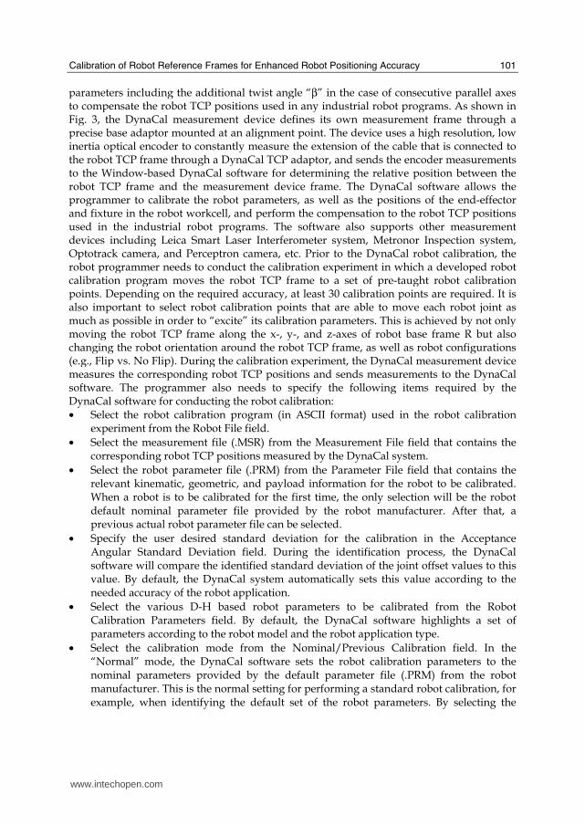
parameters including the additional twist angle “β” in the case of consecutive parallel axes to compensate the robot TCP positions used in any industrial robot programs. As shown in Fig. 3, the DynaCal measurement device defines its own measurement frame through a precise base adaptor mounted at an alignment point. The device uses a high resolution, low inertia optical encoder to constantly measure the extension of the cable that is connected to the robot TCP frame through a DynaCal TCP adaptor, and sends the encoder measurements to the Window-based DynaCal software for determining the relative position between the robot TCP frame and the measurement device frame. The DynaCal software allows the programmer to calibrate the robot parameters, as well as the positions of the end-effector and fixture in the robot workcell, and perform the compensation to the robot TCP positions used in the industrial robot programs. The software also supports other measurement devices including Leica Smart Laser Interferometer system, Metronor Inspection system, Optotrack camera, and Perceptron camera, etc. Prior to the DynaCal robot calibration, the robot programmer needs to conduct the calibration experiment in which a developed robot calibration program moves the robot TCP frame to a set of pre-taught robot calibration points. Depending on the required accuracy, at least 30 calibration points are required. It is also important to select robot calibration points that are able to move each robot joint as much as possible in order to “excite” its calibration parameters. This is achieved by not only moving the robot TCP frame along the x-, y-, and z-axes of robot base frame R but also changing the robot orientation around the robot TCP frame, as well as robot configurations (e.g., Flip vs. No Flip). During the calibration experiment, the DynaCal measurement device measures the corresponding robot TCP positions and sends measurements to the DynaCal software. The programmer also needs to specify the following items required by the DynaCal software for conducting the robot calibration: • Select the robot calibration program (in ASCII format) used in the robot calibration
experiment from the Robot File field.
• Select the measurement file (.MSR) from the Measurement File field that contains the corresponding robot TCP positions measured by the DynaCal system.
• Select the robot parameter file (.PRM) from the Parameter File field that contains the relevant kinematic, geometric, and payload information for the robot to be calibrated. When a robot is to be calibrated for the first time, the only selection will be the robot default nominal parameter file provided by the robot manufacturer. After that, a previous actual robot parameter file can be selected.
• Specify the user desired standard deviation for the calibration in the Acceptance Angular Standard Deviation field. During the identification process, the DynaCal software will compare the identified standard deviation of the joint offset values to this value. By default, the DynaCal system automatically sets this value according to the needed accuracy of the robot application.
• Select the various D-H based robot parameters to be calibrated from the Robot Calibration Parameters field. By default, the DynaCal software highlights a set of parameters according to the robot model and the robot application type.
• Select the calibration mode from the Nominal/Previous Calibration field. In the “Normal” mode, the DynaCal software sets the robot calibration parameters to the nominal parameters provided by the default parameter file (.PRM) from the robot manufacturer. This is the normal setting for performing a standard robot calibration, for example, when identifying the default set of the robot parameters. By selecting the
www.intechopen.com
Robot Manipulators
102
"Previous" mode instead, the robot calibration parameters are set to their previously calibrated values stored in the selected parameter file (.PRM). This is convenient, for example, when re-calibrating a sub-set of the robot parameters (e.g. a specific joint offset) while leaving all other parameters to their previously calibrated values. This re- calibration process would typically allow the use of less robot calibration points than that used for a standard robot calibration.
After the robot calibration, a new robot parameter file appears in the Parameter File field that contains the identified true robot parameters. The DynaCal software uses the “now-identified” actual robot parameters to modify the corresponding joint positions of all robot TCP positions used in any robot program during the DynaCal compensation process.
Figure 3. The DynaCal robot cell calibration system
3.2 Calibration of a Robot User Tool Frame
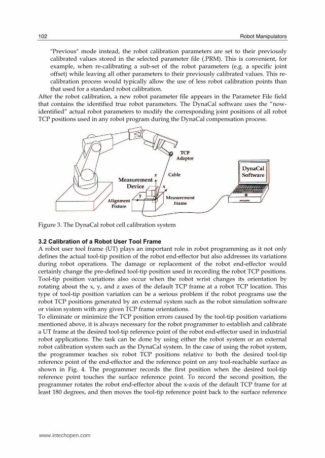
A robot user tool frame (UT) plays an important role in robot programming as it not only defines the actual tool-tip position of the robot end-effector but also addresses its variations during robot operations. The damage or replacement of the robot end-effector would certainly change the pre-defined tool-tip position used in recording the robot TCP positions. Tool-tip position variations also occur when the robot wrist changes its orientation by rotating about the x, y, and z axes of the default TCP frame at a robot TCP location. This type of tool-tip position variation can be a serious problem if the robot programs use the robot TCP positions generated by an external system such as the robot simulation software or vision system with any given TCP frame orientations. To eliminate or minimize the TCP position errors caused by the tool-tip position variations mentioned above, it is always necessary for the robot programmer to establish and calibrate a UT frame at the desired tool-tip reference point of the robot end-effector used in industrial robot applications. The task can be done by using either the robot system or an external robot calibration system such as the DynaCal system. In the case of using the robot system, the programmer teaches six robot TCP positions relative to both the desired tool-tip reference point of the end-effector and the reference point on any tool-reachable surface as shown in Fig. 4. The programmer records the first position when the desired tool-tip reference point touches the surface reference point. To record the second position, the programmer rotates the robot end-effector about the x-axis of the default TCP frame for at least 180 degrees, and then moves the tool-tip reference point back to the surface reference
www.intechopen.com
Calibration of Robot Reference Frames for Enhanced Robot Positioning Accuracy
103
point. Similarly, the programmer teaches the third position by rotating the robot end-effector about the y-axis of the default TCP frame. The other three positions are recorded after the programmer moves each axis of the default TCP frame along the corresponding axis of robot base frame R for at least one-foot distance relative to the surface reference point, respectively. The robot system uses these six recorded robot TCP positions to calculate the actual UT frame position at the tool-tip reference point and saves its value in the robot system. The UT calibration procedure also allows the established UT frame at the tool-tip position to stay at any given TCP location regardless of the orientation change of robot end-effector as shown in Fig. 4. Technically, the programmer needs to re-calibrate the UT frame each time the robot end-effector is changed, for example, after an unexpected collision. Some robot manufacturers have developed the “online robot UT frame adjustment” option for their robot systems in order to reduce the robot production downtime. The robot programmer can also simultaneously obtain an accurate UT frame position at the desired tool-tip point on the robot end-effector during the DynaCal robot calibration. The procedure is called the “DynaCal end-effector calibration.” To achieve it, the programmer needs to specify at least three non-collinear measurement points on the robot end-effector and input their locations relative to the desired tool-tip point in the DynaCal system.
Figure 4. Calibration of a robot user tool frame with the robot
During the DynaCal robot calibration, the DynaCal TCP adaptor should be mounted at each of the three measurement points in between the measurements of the robot calibration TCP points. For example, with a total of 30 robot calibration points, the first 10 calibration points are measured with the TCP adaptor at the first measurement point, the next 10 calibration points are measured with the TCP adaptor at the second measurement point, etc. However, when only UT frame location (i.e. x, y, z, ) needs to be calibrated, one measurement point on the end-effector suffices and choosing the measurement point at the desired tool-tip point further simplifies the process because its location relative to the desired tool-tip point is then simply zero. After the calibration, the DynaCal system uses the values of the measurement
www.intechopen.com

Robot Manipulators
104
points to calculate the actual UT frame position at the desired tool-tip reference point and saves the value in the parameter file (.PRM).
3.3 Calibration of Robot User Frame
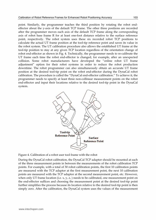
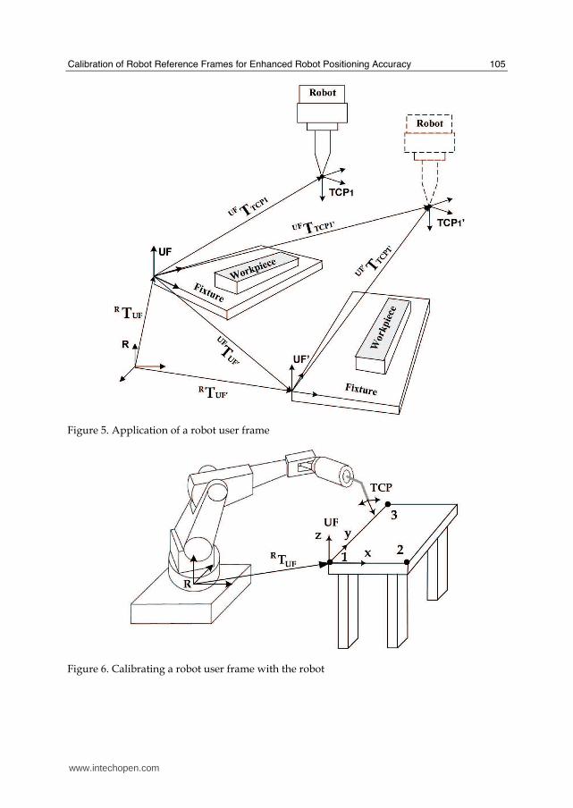
Like robot base frame R, an active robot user frame, UF, in the robot system defines the robot TCP positions as shown in Eq (4). However, unlike the robot base frame that is inside the robot body, robot user frame UF can be established relative to robot base frame R at any position within the robot work volume. The main application of robot user frame UF is to identify the position changes of robot TCP frame and robot base frame in a robot workcell. Fig. 5 shows a workpiece held by a rigid mechanism called “fixture” in a robot workcell. Often, the programmer establishes a robot user frame, UF, on the fixture and uses it in recording the required robot TCP positions for the workpiece (e.g., UFTTCP1 in Fig. 5). To do so, the programmer uses the robot and a special cylindrical-type pointer to record at least three non-collinear TCP positions in robot base frame R as shown in Fig. 6. These three reference points define the origin, x-axis, and x-y plane of the user frame, respectively. As long as the workpiece and its position remain the same, the developed robot program can accurately move the robot TCP frame to any of the pre-taught robot TCP positions (e.g., UFTTCP1). However, if the workpiece is in a different position in the workcell, the existing robot program is not able to perform the programmed robot operations to the workpiece because there are no corresponding recorded robot TCP positions (e.g., UFTTCP1’ in Fig. 5) for the robot program to use. Instead of having to manually teach each of the new required robot TCP positions (e.g., UFTTCP1’, etc.), the programmer may identify the position change or “offset” of the user frame on the fixture denoted as transformation UFTUF in Fig. 5. With identified transformation UFTUF’, Eq. (7) and Eq. (8) are able to change all existing robot TCP positions (e.g., UFTTCP1) into their corresponding ones (e.g., UFTTCP1’) for the workpiece in the new position:
(7)
(8)
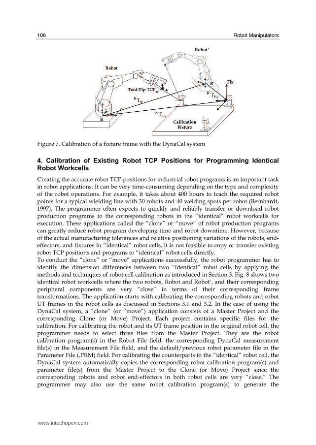
Fig. 7 shows another application in which robot user frame UF serves as a common calibration fixture frame for measuring the relative position between two robot base frames R and R’. The programmer can establish and calibrate the position of the fixture frame by using the DynaCal system rather than the robot system as mentioned earlier. Prior to that, the programmer has to perform the DynaCal end-effector calibration as introduced in Section 3.2. During the DynaCal fixture calibration, the programmer needs to mount the DynaCal measurement device at three (or four) non-collinear alignment points on the fixture as shown in Fig. 7. The DynaCal measurement device measures each alignment point relative to robot base frame R (or R’) through the DynaCal cable and TCP adaptor connected to the end-effector. The DynaCal software uses the measurements to determine the transformation between fixture frame Fix (or Fix’) and robot base frame R (or R’), denoted as RTFix (or R’TFix) in Fig. 7. After the fixture calibration, the DynaCal system calculates the relative position between two robot base frames R and R’, denoted as RTR’, in Fig. 7, and saves the result in the alignment file (.ALN).
www.intechopen.com
Calibration of Robot Reference Frames for Enhanced Robot Positioning Accuracy
105
Figure 5. Application of a robot user frame
Figure 6. Calibrating a robot user frame with the robot
www.intechopen.com
Robot Manipulators
106
Figure 7. Calibration of a fixture frame with the DynaCal system
4. Calibration of Existing Robot TCP Positions for Programming Identical Robot Workcells
Creating the accurate robot TCP positions for industrial robot programs is an important task in robot applications. It can be very time-consuming depending on the type and complexity of the robot operations. For example, it takes about 400 hours to teach the required robot points for a typical wielding line with 30 robots and 40 welding spots per robot (Bernhardt, 1997). The programmer often expects to quickly and reliably transfer or download robot production programs to the corresponding robots in the “identical” robot workcells for execution. These applications called the “clone” or “move” of robot production programs can greatly reduce robot program developing time and robot downtime. However, because of the actual manufacturing tolerances and relative positioning variations of the robots, end-effectors, and fixtures in “identical” robot cells, it is not feasible to copy or transfer existing robot TCP positions and programs to “identical” robot cells directly. To conduct the “clone” or “move” applications successfully, the robot programmer has to identify the dimension differences between two “identical” robot cells by applying the methods and techniques of robot cell calibration as introduced in Section 3. Fig. 8 shows two identical robot workcells where the two robots, Robot and Robot’, and their corresponding peripheral components are very “close” in terms of their corresponding frame transformations. The application starts with calibrating the corresponding robots and robot UT frames in the robot cells as discussed in Sections 3.1 and 3.2. In the case of using the DynaCal system, a “clone” (or “move”) application consists of a Master Project and the corresponding Clone (or Move) Project. Each project contains specific files for the calibration. For calibrating the robot and its UT frame position in the original robot cell, the programmer needs to select three files from the Master Project. They are the robot calibration program(s) in the Robot File field, the corresponding DynaCal measurement file(s) in the Measurement File field, and the default/previous robot parameter file in the Parameter File (.PRM) field. For calibrating the counterparts in the “identical” robot cell, the DynaCal system automatically copies the corresponding robot calibration program(s) and parameter file(s) from the Master Project to the Clone (or Move) Project since the corresponding robots and robot end-effectors in both robot cells are very “close.” The programmer may also use the same robot calibration program(s) to generate the
www.intechopen.com
Calibration of Robot Reference Frames for Enhanced Robot Positioning Accuracy
107
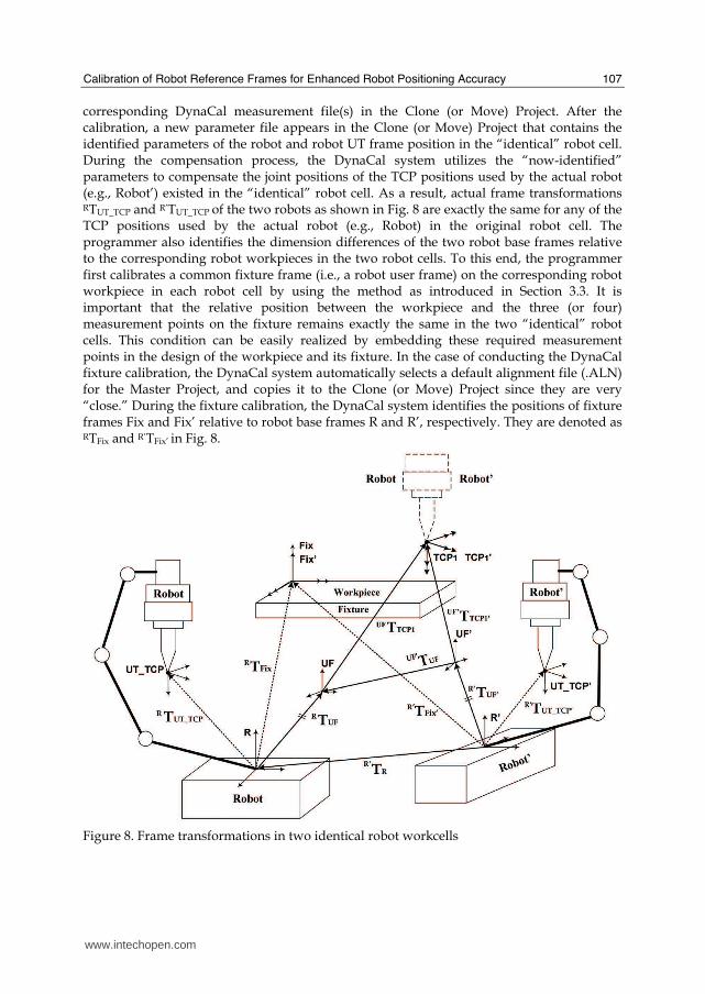
corresponding DynaCal measurement file(s) in the Clone (or Move) Project. After the calibration, a new parameter file appears in the Clone (or Move) Project that contains the identified parameters of the robot and robot UT frame position in the “identical” robot cell. During the compensation process, the DynaCal system utilizes the “now-identified” parameters to compensate the joint positions of the TCP positions used by the actual robot (e.g., Robot’) existed in the “identical” robot cell. As a result, actual frame transformations RTUT_TCP and R’TUT_TCP of the two robots as shown in Fig. 8 are exactly the same for any of the TCP positions used by the actual robot (e.g., Robot) in the original robot cell. The programmer also identifies the dimension differences of the two robot base frames relative to the corresponding robot workpieces in the two robot cells. To this end, the programmer first calibrates a common fixture frame (i.e., a robot user frame) on the corresponding robot workpiece in each robot cell by using the method as introduced in Section 3.3. It is important that the relative position between the workpiece and the three (or four) measurement points on the fixture remains exactly the same in the two “identical” robot cells. This condition can be easily realized by embedding these required measurement points in the design of the workpiece and its fixture. In the case of conducting the DynaCal fixture calibration, the DynaCal system automatically selects a default alignment file (.ALN) for the Master Project, and copies it to the Clone (or Move) Project since they are very “close.” During the fixture calibration, the DynaCal system identifies the positions of fixture frames Fix and Fix’ relative to robot base frames R and R’, respectively. They are denoted as RTFix and R’TFix’ in Fig. 8.
Figure 8. Frame transformations in two identical robot workcells
www.intechopen.com
Robot Manipulators
108
After identifying the dimension differences of the two “identical” robot workcells, the programmer can start the compensation process by changing the robot TCP positions used in the original robot cell into the corresponding ones for the “identical” robot cell. The following frame transformation equations show the method. Given that the coincidence of fixture frames Fix and Fix’ as shown in Fig. 8 represents the common calibration fixture used in the two “identical” robot cells, then, Eq. (9) calculates the transformation between two robot base frames R’ and R as:
(9)
In the case of fixture calibration in the “identical” robot cell, the DynaCal system calculates R’TR in Eq. (9) and saves the value in a new alignment file in the Clone (or Move) Project. It is also possible to make transformation R’TUF’ equal to transformation RTUF as shown in Eq. (10):
(10)
where user frames UF and UF’ are used in recording the robot TCP positions (e.g., TCP1 and TCP1’ in Fig. 8) in the two “identical” robot cells, respectively. With the results from Eq. (9) and Eq. (10), Eq. (11) calculates the relative position between two user frames UF’ and UF as:
UFR
R'R1
'UF'R
UF'UF TT)T(T ××= − (11)
After UF’TUF is identified, Eq. (12) is able to change any existing robot TCP position (e.g., UFTTCP1) for the robot workpiece in the original robot cell into the new one (e.g., UF’TTCP1’) for the corresponding robot workpiece in the “identical” robot cell:
(12)
In the DynaCal system, a successful “clone’ (or “move”) application generates a destination robot program file (in ASCII format) in the Robot File field of the Clone (or Move) Project that contains all modified robot TCP positions. The programmer then converts the file into an executable robot program with the file translation service provided by the robot manufacturer, and executes it in the actual robot controller with the expected accuracy of the robot TCP positions. For example, in the “clone” application conducted for two “identical” FANUC robot cells (Cheng, 2007), the DynaCal system successfully generated the destination FANUC Teach Pendant (TP) program after the robot cell calibration and compensation. The programmer used the FANUC PC File Service software to convert the ASCII robot file into the executable FANUC TP program and download it to the actual FANUC M6i robot in the “identical” cell for execution. As a result, the transferred robot program allowed the FANUC robot to complete the same operations to the workpiece in the “identical” robot cell within the robot TCP position accuracy of 0.5 mm.
5. Calibration of Simulated Robot TCP Positions for Robot Offline Programming
Offline robot programming is, by definition, the technique of generating reliable, efficient, and executable robot TCP positions and programs without using a real robot. One approach is to use the commercial robot simulation software such as IGRIP developed by Delmia
www.intechopen.com
Calibration of Robot Reference Frames for Enhanced Robot Positioning Accuracy
109
Corporation (Cheng, 2003). This new method represents several advantages over the conventional “online robot programming method” in terms of improved robot workcell design and reduced robot downtime. However, there are inevitable differences between the simulated robot workcell and the corresponding actual one due to the manufacturing tolerance and the poisoning variations of the robot workcell components. Among them, the positioning differences of robot “zero” joint positions, robot base frames and UT frames cause 80 percent of the inaccuracy in a typical robot simulation workcell. Therefore, it is not feasible to download the robot TCP positions and programs created in the robot simulation workcell to the actual robot controller for execution directly. Calibrating the robotic and non-robotic device models in the simulation workcell makes it possible to conduct the true simulation-based offline robot programming. The method uses the calibration functions provided by the robot simulation software (e.g., IGRIP) and a number of actually measured robot TCP positions in the real robot cell to modify the nominal values of the robot simulation workcell including robot parameters, and positions of robot base frame, UT frame, and fixture frame. The successful application of the technology allows robot TCP positions and programs to be created in the nominal simulation workcell, verified in the calibrated simulation workcell, and finally downloaded to the actual robot controllers for execution.
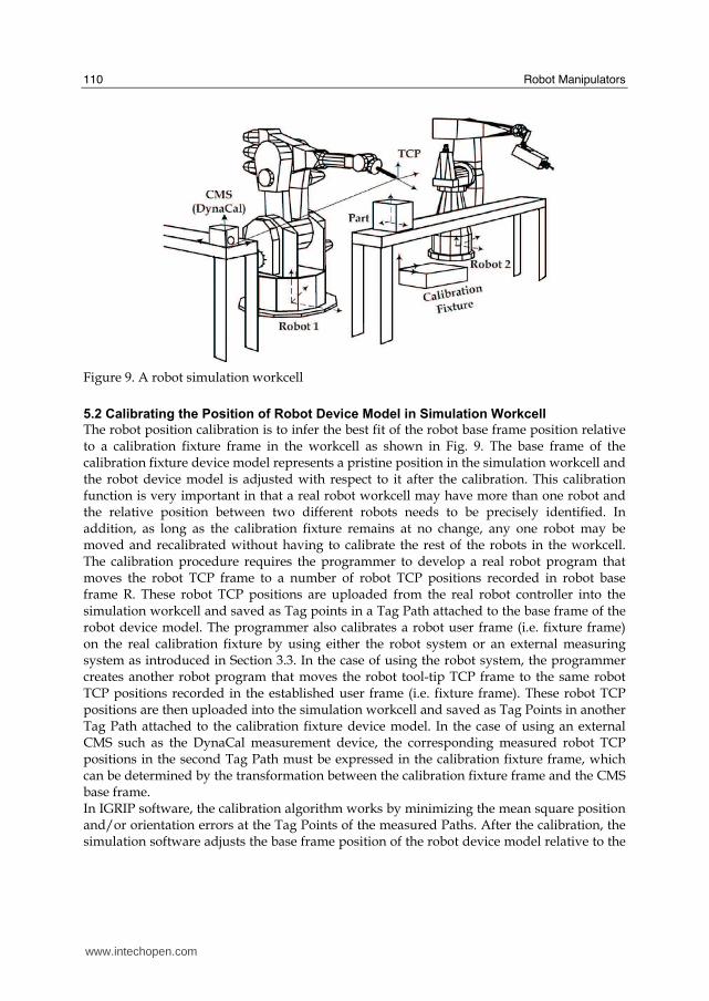
5.1 Calibrating Robot Device Model in Robot Simulation Workcell
The purpose of calibrating a robot device model in the simulation workcell is to infer the best fit of the robot kinematic parameters and UT frame position based on a number of measured robot TCP positions. The IGRIP simulation software uses non-linear least squares model fitting with the Levenberg-Marquardt method to obtain the parameter identification solution. The calibration procedure consists of three steps. First, in the simulation workcell the programmer selects both the robot device model to be calibrated and the device model that represents the actual external coordinate measurement system (CMS) such as the DynaCal measurement device in Fig. 9. The position of the CMS device model in the simulation workcell represents a starting guess of the true CMS position in the actual robot workcell. Second, the programmer develops a robot calibration program that moves the actual default robot TCP frame to a number of pre-taught robot calibration TCP positions. The actual external CMS such as the DynaCal measuring device also measures each of these robot TCP positions. Finally, the programmer uploads the two sets of robot calibration TCP positions into the simulation workcell and saves them as Tag Points in two Tag Paths. The first Tag Path contains the coordinates of the default TCP frame positions at the corresponding robot calibration TCP positions used by the robot calibration program. They are uploaded from the actual robot controller and attached to the base of the robot device model in the simulation workcell. The second Tag Path contains the coordinates of the corresponding robot calibration TCP positions measured by the external CMS. They are uploaded from the actual CMS and attached to the corresponding CMS device model in the simulation workcell. In IGRIP software, the robot calibration algorithm works by minimizing the mean square position error at the Tag Points of the measured Paths. After the robot calibration, the simulation software adjusts the nominal parameters of the robot device model (i.e. “zero” joint positions and UT frame position) in the simulation workcell for the best fit of the corresponding real identified parameters.
www.intechopen.com
Robot Manipulators
110
Figure 9. A robot simulation workcell
5.2 Calibrating the Position of Robot Device Model in Simulation Workcell
The robot position calibration is to infer the best fit of the robot base frame position relative to a calibration fixture frame in the workcell as shown in Fig. 9. The base frame of the calibration fixture device model represents a pristine position in the simulation workcell and the robot device model is adjusted with respect to it after the calibration. This calibration function is very important in that a real robot workcell may have more than one robot and the relative position between two different robots needs to be precisely identified. In addition, as long as the calibration fixture remains at no change, any one robot may be moved and recalibrated without having to calibrate the rest of the robots in the workcell. The calibration procedure requires the programmer to develop a real robot program that moves the robot TCP frame to a number of robot TCP positions recorded in robot base frame R. These robot TCP positions are uploaded from the real robot controller into the simulation workcell and saved as Tag points in a Tag Path attached to the base frame of the robot device model. The programmer also calibrates a robot user frame (i.e. fixture frame) on the real calibration fixture by using either the robot system or an external measuring system as introduced in Section 3.3. In the case of using the robot system, the programmer creates another robot program that moves the robot tool-tip TCP frame to the same robot TCP positions recorded in the established user frame (i.e. fixture frame). These robot TCP positions are then uploaded into the simulation workcell and saved as Tag Points in another Tag Path attached to the calibration fixture device model. In the case of using an external CMS such as the DynaCal measurement device, the corresponding measured robot TCP positions in the second Tag Path must be expressed in the calibration fixture frame, which can be determined by the transformation between the calibration fixture frame and the CMS base frame. In IGRIP software, the calibration algorithm works by minimizing the mean square position and/or orientation errors at the Tag Points of the measured Paths. After the calibration, the simulation software adjusts the base frame position of the robot device model relative to the
www.intechopen.com
Calibration of Robot Reference Frames for Enhanced Robot Positioning Accuracy
111
base frame of the calibration fixture device model, which results in the best fit of the robot base frame position.
5.3 Calibrating Non-Robotic Device Model in Simulation Workcell
This type of calibration is usually the last step in the overall simulation workcell calibration. It intends to adjust the position of a non-kinematic model such as a workpiece or a table relative to robot base frame R and UT frame in the robot simulation workcell in order to match the counterpart in the real robot workcell. The method uses measurements from the actual robot workcell. After the calibration, the programs developed in the robot simulation workcell will contain the corrected robot TCP positions that can be directly downloaded to the actual robot workcell. The calibration procedure requires the programmer to create three non-collinear feature Tag points on the workpiece device model in the robot simulation workcell and save them in the first Tag Path attached to the workpiece device model. Then, the programmer develops a real robot program that moves the tool-tip TCP frame to the corresponding three points on the real workpiece. These robot TCP positions are then uploaded from the actual robot controller and saved as Tag Points in the second Tag Path attached to the workpiece device model. During the calibration, the simulation software moves the workpiece device model in simulation workcell by matching up the first set of three Tag Points with the second set. Other methods such as the six-point method and the Least Squares method allow the programmer to use more robot points on the workpiece for conducting the same calibration.
6. Conclusion
This chapter discussed the importance and methods of conducting robot workcell calibration for enhancing the accuracy of the robot TCP positions in industrial robot applications. It shows that the robot frame transformations define the robot geometric parameters such as joint position variables, link dimensions, and joint offsets in an industrial robot system. The D-H representation allows the robot designer to model the robot motion geometry with the four standard D-H parameters. The robot kinematics equations use the robot geometric parameters to calculate the robot TCP positions for industrial robot programs. The discussion also shows that because of the geometric effects, the true geometric parameters of an industrial robot or a robot workcell are often different from the corresponding ones used by the robot kinematic model, or “identical” robots and robot workcells, which results in robot TCP position errors. Throughout the chapter, it has been emphasized that the model-based robot calibration methods are able to minimize the robot TCP position errors through identifying the true geometric parameters of a robot and robot workcell based on the measurements of strategically planned robot TCP positions and the mathematical solutions of non-linear least squares optimization. The discussions have provided readers with the methods of calibrating the robot, end-effector, and fixture in the robot workcell. The integrated calibration solution shows that the robot programmer is able to use the calibration functions provided by the robot systems and commercial products such as the DynaCal Robot Cell Calibration System and IGRIP robotic simulation software to conduct true offline robot programming for “identical” and simulated robot cells with enhanced accuracy of robot TCP positions. The successful applications of the robot cell calibration techniques bring
www.intechopen.com
Robot Manipulators
112
great benefits to industrial robot applications in terms of reduced robot program developing time and robot production downtime.
7. References
Abderrahim, M. & Whittaker, A. R. (2000). Kinematic Model Identification of Industrial Manipulators, Robotics and Computer-Integrated Manufacturing, Vol. 16, No. 1, February 2000, pp 1-8.
Bernhardt, R. (1997). Approaches for Commissioning Time Reduction, Industrial Robot, Vol. 24, No. 1, pp. 62-71.
Cheng, S. F. (2007). The Method of Recovering TCP Positions in Industrial Robot Production Programs, Proceedings of 2007 IEEE International Conference on Mechatronics and Automation, August 2007, pp. 805-810.
Cheng, S. F. (2003). The Simulation Approach for Designing Robotic Workcells, Journal of Engineering Technology, Vol. 20, No. 2, Fall 2003, pp. 42-48.
Denavit, J. & Hartenberg, R. S. (1955). Kinematic Modelling for Robot Calibration, Trans. ASME Journal of Applied Mechanics, Vol. 22, June 1955, pp. 215-221.
Dennis, J. E. & Schnabel, R. B. (1983). Numerical Methods for Unconstrained Optimization and Nonlinear Equations, New Jersey: Prentice-Hall.
Driels, M. R. & Pathre, U. S. (1990). Significance of Observation Strategy on the Design of Robot Calibration Experiments, Journal of Robotic Systems, Vol. 7, No. 2, pp. 197-223.
Greenway, B. (2000). Robot Accuracy, Industrial Robot, Vol. 27, No. 4,2000, pp 257-265. Mooring, B., Roth, Z. and Driels, M. (1991). Fundamentals of manipulator calibration, Wiley,
New York. Motta, J. M. S. T., Carvalho, G. C. and McMaster, R. S. (2001). Robot Calibration Using a 3-D
Vision-Based Measurement System with a Single Camera, Robotics and Computer-Integrated Manufacturing, Ed. Elsevier Science, U.K., Vol. 17, No. 6, pp. 457-467.
Roth, Z. S., Mooring, B. W. and Ravani, B. (1987). An Overview of Robot Calibration, IEEE Journal of Robotics and Automation, RA-3, No. 3, pp. 377-85.
Schroer, K. (1993). Theory of Kinematic Modeling and Numerical Procedures for Robot Calibration, Robot Calibration, Chapman & Hall, London.
Stone H. W. (1987). Kinematic modeling, identification, and control of robotic manipulators. Kluwer Academic Publishers.
www.intechopen.com
Robot ManipulatorsEdited by Marco Ceccarelli
ISBN 978-953-7619-06-0Hard cover, 546 pagesPublisher InTechPublished online 01, September, 2008Published in print edition September, 2008
InTech EuropeUniversity Campus STeP Ri Slavka Krautzeka 83/A 51000 Rijeka, Croatia Phone: +385 (51) 770 447 Fax: +385 (51) 686 166www.intechopen.com
InTech ChinaUnit 405, Office Block, Hotel Equatorial Shanghai No.65, Yan An Road (West), Shanghai, 200040, China
Phone: +86-21-62489820 Fax: +86-21-62489821
In this book we have grouped contributions in 28 chapters from several authors all around the world on theseveral aspects and challenges of research and applications of robots with the aim to show the recentadvances and problems that still need to be considered for future improvements of robot success in worldwideframes. Each chapter addresses a specific area of modeling, design, and application of robots but with an eyeto give an integrated view of what make a robot a unique modern system for many different uses and futurepotential applications. Main attention has been focused on design issues as thought challenging for improvingcapabilities and further possibilities of robots for new and old applications, as seen from today technologiesand research programs. Thus, great attention has been addressed to control aspects that are stronglyevolving also as function of the improvements in robot modeling, sensors, servo-power systems, andinformatics. But even other aspects are considered as of fundamental challenge both in design and use ofrobots with improved performance and capabilities, like for example kinematic design, dynamics, visionintegration.
How to referenceIn order to correctly reference this scholarly work, feel free to copy and paste the following:
Frank Shaopeng Cheng (2008). Calibration of Robot Reference Frames for Enhanced Robot PositioningAccuracy, Robot Manipulators, Marco Ceccarelli (Ed.), ISBN: 978-953-7619-06-0, InTech, Available from:http://www.intechopen.com/books/robot_manipulators/calibration_of_robot_reference_frames_for_enhanced_robot_positioning_accuracy

© 2008 The Author(s). Licensee IntechOpen. This chapter is distributedunder the terms of the Creative Commons Attribution-NonCommercial-ShareAlike-3.0 License, which permits use, distribution and reproduction fornon-commercial purposes, provided the original is properly cited andderivative works building on this content are distributed under the samelicense.