Embed Size (px)
Citation preview

Calibration with trihedral corner reflectors: a case study using satellite-based X, C and L- band frequency Synthetic Aperture Radar data over Queensland, Australia Medhavy Thankappan1, Matthew Garthwaite1, Peter Meadows2, Nuno Miranda3, Adrian Schubert4 and David Small4
1Geoscience Australia, Canberra, Australia 2BAE Systems Applied Intelligence, Essex, United Kingdom 3European Space Agency, Frascati, Italy 4 Remote Sensing Laboratories, Department of Geography, University of Zurich, Switzerland

Acknowledgments
CEOS SAR Workshop 2015, ESA-ESTEC, Netherlands 27-29 October 2015
Gunning Grazing Company

Australian Geophysical Observing System (AGOS) 4 CORS GNSS stations Repository of SAR data
GNSS instrumentation pool Robotic GNSS antenna calibration facility
Geodetic network
CEOS SAR Workshop 2015, ESA-ESTEC, Netherlands 27-29 October 2015

• Four sizes, 1.0 m 1.5 m, 2.0 m and 2.5 m
• Experiment with three surface finishes in the 1.5 m size
• 18 prototypes in total
Prototype Reflectors
Untreated Aluminium Powder Coated Perforated Aluminium
CEOS SAR Workshop 2015, ESA-ESTEC, Netherlands 27-29 October 2015

Characterisation of Reflectors
Used the DSTO outdoor radar ground reflection range in Adelaide, SA in June 2013
Performed tests at X-band and C-band
Tested all twelve 1.0 m and 1.5 m reflectors
CEOS SAR Workshop 2015, ESA-ESTEC, Netherlands 27-29 October 2015

CR Characterisation Results
CEOS SAR Workshop 2015, ESA-ESTEC, Netherlands 27-29 October 2015
• Consistent results for C-band • Less consistent for X-band
1.0 m
Plain sheet
Pow
der-coated
Mesh

Gunning Grazing Company, Dec 2013 – May 2014
CEOS SAR Workshop 2015, ESA-ESTEC, Netherlands 27-29 October 2015
Field Deployment for Evaluation (Gunning Site)
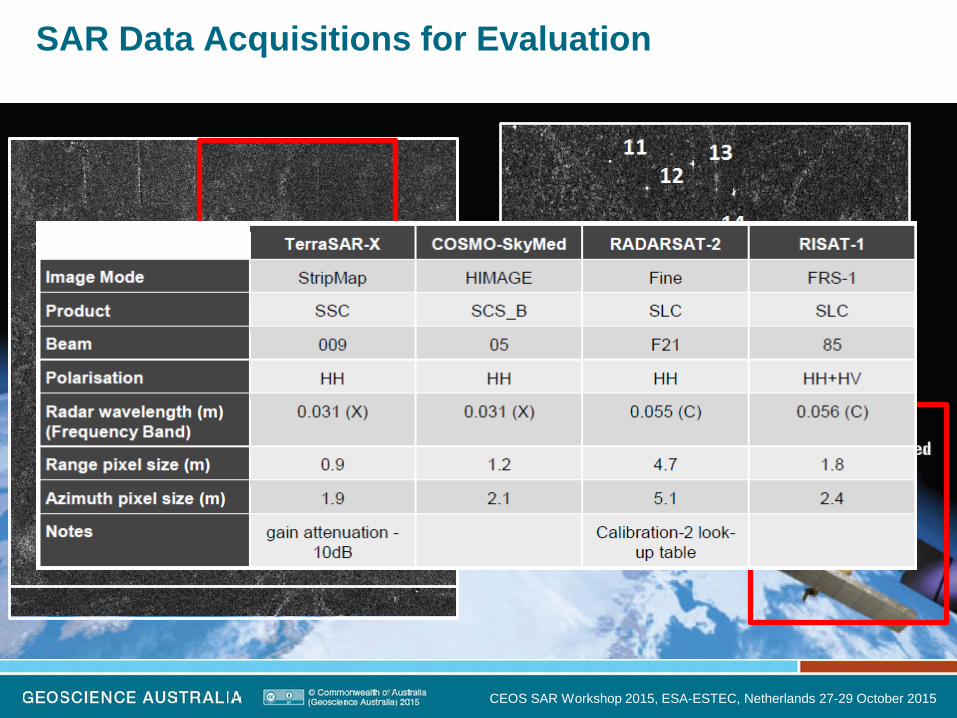
SAR Data Acquisitions for Evaluation
CEOS SAR Workshop 2015, ESA-ESTEC, Netherlands 27-29 October 2015

Clutter Intensity: Temporal Changes
CEOS SAR Workshop 2015, ESA-ESTEC, Netherlands 27-29 October 2015

LOS Height Error
<0.5 mm at C-band
<0.1 mm at X-band
CEOS SAR Workshop 2015, ESA-ESTEC, Netherlands 27-29 October 2015

RCS vs Clutter Intensity
CEOS SAR Workshop 2015, ESA-ESTEC, Netherlands 27-29 October 2015
http://www.ga.gov.au/metadata-gateway/metadata/record/82751/

CR Design for AGOS (Queensland Array)
The 1.5 m triangular trihedral corner reflector was chosen for final deployment in the Surat Basin; 34 installed.
Three 2.0 m and three 2.5 m prototypes also installed.
CEOS SAR Workshop 2015, ESA-ESTEC, Netherlands 27-29 October 2015
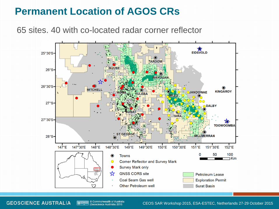
Permanent Location of AGOS CRs
65 sites. 40 with co-located radar corner reflector
CEOS SAR Workshop 2015, ESA-ESTEC, Netherlands 27-29 October 2015

CR Positions
Positions of all CR sites obtained with RTK
Mean 2σ uncertainty of 2 cm horizontal and 4 cm vertical
CEOS SAR Workshop 2015, ESA-ESTEC, Netherlands 27-29 October 2015

CR Coordinates
CEOS SAR Workshop 2015, ESA-ESTEC, Netherlands 27-29 October 2015
http://www.tandfonline.com/doi/full/10.1080/08120099.2015.1040073#.Vim8lvmqpBc
Link to paper with details of CR coordinates

Signal-to-Clutter Ratio
CEOS SAR Workshop 2015, ESA-ESTEC, Netherlands 27-29 October 2015
# SAR images # reflectors imaged Mean SCR Std. Dev. ~ Height Error (mm)
TerraSAR-X 11 11 49.57 3.19 0.005 Sentinel-1A 3 38 32.00 2.85 0.194
RADARSAT-2 8 40 36.18 2.17 0.122 ALOS-2 11 36 29.86 6.14 4.641

Sentinel 1A: Radiometric Calibration
CEOS SAR Workshop 2015, ESA-ESTEC, Netherlands 27-29 October 2015
• Orientation of the CR array is fixed currently not specifically set for S1A • Elevation and azimuth offset between the CR and SAR boresight angles
IW
S1A_IW_GRDH_1SDV_20141217T084036_20141217T084101_003756_0047A9_3129.SAFE

Results for VV
CEOS SAR Workshop 2015, ESA-ESTEC, Netherlands 27-29 October 2015
VV
VV
• Stability of individual CRs has been assessed (separately for VV and HH pol):
• All IW acquisitions are from the same track – some variability, especially for orbit 5788. Normalising each product reduces the IW STD from 0.37 to 0.21 dB:

CEOS SAR Workshop 2015, ESA-ESTEC, Netherlands 27-29 October 2015
• The S1 relative RCS offset is due to the elevation pointing of the CRs (theoretical RCS curve for a trihedral curve assumes that the CR Azimuth offset is zero):
An azimuth offset of 2° leads to a reduction in RCS of just 0.02dB.
VV
VV
• IW and SM standard deviation
Results for VV - contd.

CEOS SAR Workshop 2015, ESA-ESTEC, Netherlands 27-29 October 2015
• HH pol relative RCS:
• Normalising relative RCS. No change in IW STD:
HH
HH
Results for HH

HH and VV
CEOS SAR Workshop 2015, ESA-ESTEC, Netherlands 27-29 October 2015
• The IW standard deviation:
N.B. 2.5m CRs are 3, 5 & 14; 2.0m CRs are 4, 8 & 9
HH and VV

Sentinel-1A Geometric Calibration
CEOS SAR Workshop 2015, ESA-ESTEC, Netherlands 27-29 October 2015

ALOS2: L-band Calibration
Six 2.5 m and 2.0 m CR being used as ongoing calibration targets by JAXA for their L-band SAR mission ALOS-2
CEOS SAR Workshop 2015, ESA-ESTEC, Netherlands 27-29 October 2015

Summary
• An array of 40 CRs of 1.5, 2.0 and 2.5m sizes deployed in Queensland, Australia; some CRs individually characterised for RCS; designed to support SAR calibration
• Ongoing data acquisition over array with X, C and L-band SAR systems for calibration
• Sentinel-1A radiometric calibration (IW and SM): stability of CRs assessed for VV and HH; RCS variability attributed to CR elevation / azimuth offsets with boresight
• Sentinel-1A geometric calibration IW and SM: overall SM scatter similar to IW SLC scatter plot; some observed anomalies being investigated
• The 2.0m / 2.5m CRs are optimally oriented for ongoing calibration of ALOS-2; flexibility to support specific missions
CEOS SAR Workshop 2015, ESA-ESTEC, Netherlands 27-29 October 2015