Embed Size (px)
Citation preview
5500AMulti-Product
CalibratorExtended Specifications
2005
5500A Black and White Extended Specifications Fluke Corporation 1
5500A Specifications The following paragraphs detail specifications for the 5500A Calibrator. The specifications are valid after allowing a warm-up period of 30 minutes, or twice the time the 5500A has been turned off. For example, if the 5500A has been turned off for 5 minutes, the warm-up period is 10 minutes.
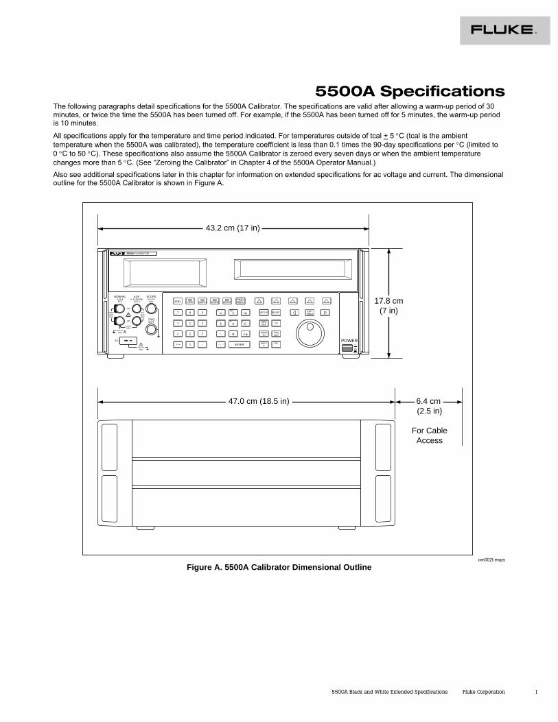
All specifications apply for the temperature and time period indicated. For temperatures outside of tcal + 5 °C (tcal is the ambient temperature when the 5500A was calibrated), the temperature coefficient is less than 0.1 times the 90-day specifications per °C (limited to 0 °C to 50 °C). These specifications also assume the 5500A Calibrator is zeroed every seven days or when the ambient temperature changes more than 5 °C. (See “Zeroing the Calibrator” in Chapter 4 of the 5500A Operator Manual.) Also see additional specifications later in this chapter for information on extended specifications for ac voltage and current. The dimensional outline for the 5500A Calibrator is shown in Figure A.
POWERI
O
0
1 2 3
4 5 6
7 8 9
ENTER
M
k
m V Hz FIELDEDIT
/+
F
OPR EARTH SCOPE BOOST MENUPREV
SHIFT
RESET
CE
SETUP
REFNEW
TCMEAS
¡F
µ
n
p
W
dBm sec
¡CA
MULTx
DIV
OUTTRIG
5500A CALIBRATOR
20V PK MAX
HI
LO
TC
TRIGOUT
1000V RMSMAX
20V RMSMAX
1V PKMAX
20V PK MAX
NORMAL AUX SCOPEV, ,RTD
A, -SENSE, AUX V
200V PK MAX STBY
43.2 cm (17 in)
47.0 cm (18.5 in) 6.4 cm (2.5 in)
For CableAccess
17.8 cm(7 in)
om002f.ewps
Figure A. 5500A Calibrator Dimensional Outline
2 Fluke Corporation 5500A Black and White Extended Specifications
General Specifications Warmup Time Twice the time since last warmed up, to a maximum of 30 minutes. Settling Time Less than 5 seconds for all functions and ranges except as noted. Standard Interfaces IEEE-488 (GPIB), RS-232, 5725A Amplifier Temperature Performance • Operating: 0 °C to 50 °C
• Calibration (tcal): 15 °C to 35 °C
• Storage: -20 °C to 70 °C Temperature Coefficient Temperature Coefficient for temperatures outside tcal +5 °C is 0.1X/ °C of the 90-day
specification (or 1-year, as applicable) per °C. Relative Humidity [1] • Operating: <80 % to 30 °C, <70 % to 40 °C, <40 % to 50 °C
• Storage: <95 %, non-condensing Altitude • Operating: 3,050 m (10,000 ft) maximum
• Non-operating: 12,200 m (40,000 ft) maximum Safety Complies with IEC 1010-1 (1992-1); ANSI/ISA-S82.01-1994;
CAN/CSA-C22.2 No. 1010.1-92 Analog Low Isolation 20 V EMC Designed to comply with FCC Rules Part 15; VFG 243/1991. If used in areas with
Electromagnetic fields of 1 to 3 V/m, resistance outputs have a floor adder of 0.508 Ω. Performance not specified above 3 V/m. This instrument may be susceptible to electro-static discharge (ESD) from direct contact to the binding posts. Good static aware practices should be followed when handling this and other pieces of electronic equipment.
Line Power • Line Voltage (selectable): 100 V, 120 V, 220 V, 240 V
• Line Frequency: 47 Hz to 63 Hz
• Line Voltage Variation: ±10 % about line voltage setting Power Consumption 5500A Calibrator, 300 VA; 5725A Amplifier, 750 VA Dimensions 5500A Calibrator:
• Height: 17.8 cm (7 in), standard rack increment, plus 1.5 cm (0.6 in) for feet on bottom of unit
• Width, 43.2 cm (17 in), standard rack width
• Depth: 47.3 cm (18.6 in) overall 5725A Amplifier:
• Height, 13.3 cm (5.25 in), standard rack increment, plus 1.5 cm (0.6 in) for feet on bottom of unit
• Width, 43.2 cm (17 in), standard rack width
• Depth, 63.0 cm (24.8 in) overall. Weight (without options) 5500A Calibrator, 22 kg (49 lb); 5725A Amplifier 32 kg (70 lb) Absolute Uncertainty Definition The 5500A specifications include stability, temperature coefficient, linearity, line and
load regulation, and the traceability of the external standards used for calibration. You do not need to add anything to determine the total specification of the 5500A for the temperature range indicated.
Specification Confidence Interval
99 %
[1] After long periods of storage at high humidity, a drying out period (with the power on) of at least one week may be required.
5500A Black and White Extended Specifications Fluke Corporation 3
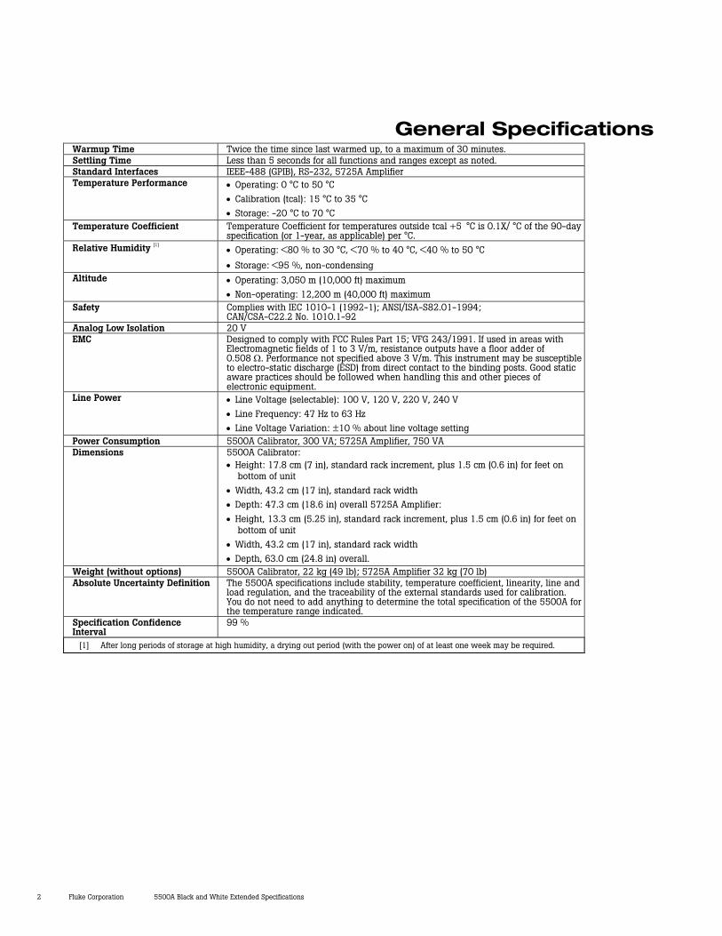
Electrical Specifications DC Voltage Specifications
Absolute Uncertainty, tcal ± 5 °C ± (% of output + µV)
Stability 24 hours, ± 1 °C Range
90 days 1 year ± (ppm output + µV)
Resolution µV
Maximum Burden [1]
0 to 329.9999 mV 0.005 3 0.006 3 5 ppm + 1 0.1 50 Ω 0 to 3.299999 V 0.004 5 0.005 5 4 + 3 1 10 mA 0 to 32.99999 V 0.004 50 0.005 50 4 + 30 10 10 mA
30 to 329.9999 V 0.004 500 0.0055 500 4.5 + 300 100 5 mA 100 to 1020.000 V 0.0045 1500 0.0055 1500 4.5 + 900 1000 5 mA
Auxiliary Output (dual output mode only) [2] 0 to 329.999 mV 0.03 350 0.04 350 30 + 100 1 5 mA
0.33 to 3.3 V 0.03 350 0.04 350 30 + 100 10 5 mA [1] Remote sensing is not provided. Output resistance is < 5 mΩ for outputs ≥ 0.33 V. The AUX output has an output resistance
of < 1 Ω.
[2] Two channels of dc voltage output are provided.
Noise Range Bandwidth 0.1 to 10 Hz p-p
± (ppm output + µV) Bandwidth 10 to 10 kHz rms
0 to 329.9999 mV 1 µV 4 µV 0 to 3.299999 V 10 µV 50 µV 0 to 32.99999 V 100 µV 600 µV
30 to 329.9999 V 10 ppm + 1 mV 20 mV 100 to 1020.000 V 10 ppm + 5 mV 20 mV
Auxiliary Output (dual output mode only) [1] 0 to 329.999 mV 5 µV 20 µV
0.33 to 3.3 V 20 µV 200 µV [1] Two channels of dc voltage output are provided.
4 Fluke Corporation 5500A Black and White Extended Specifications
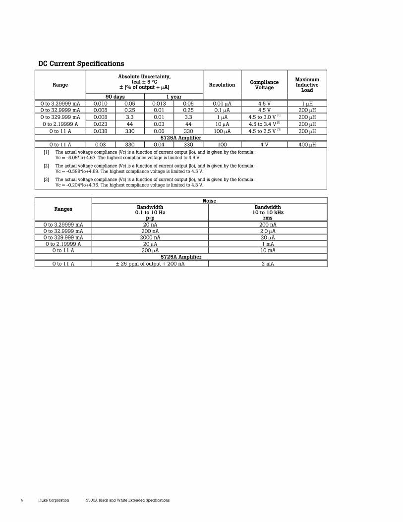
DC Current Specifications
Absolute Uncertainty, tcal ± 5 °C
± (% of output + µA) Range
90 days 1 year
Resolution Compliance Voltage
Maximum Inductive
Load
0 to 3.29999 mA 0.010 0.05 0.013 0.05 0.01 µA 4.5 V 1 µH 0 to 32.9999 mA 0.008 0.25 0.01 0.25 0.1 µA 4.5 V 200 µH 0 to 329.999 mA 0.008 3.3 0.01 3.3 1 µA 4.5 to 3.0 V [1] 200 µH 0 to 2.19999 A 0.023 44 0.03 44 10 µA 4.5 to 3.4 V [2] 200 µH
0 to 11 A 0.038 330 0.06 330 100 µA 4.5 to 2.5 V [3] 200 µH 5725A Amplifier
0 to 11 A 0.03 330 0.04 330 100 4 V 400 µH [1] The actual voltage compliance (Vc) is a function of current output (Io), and is given by the formula:
Vc = -5.05*Io+4.67. The highest compliance voltage is limited to 4.5 V.
[2] The actual voltage compliance (Vc) is a function of current output (Io), and is given by the formula: Vc = -0.588*Io+4.69. The highest compliance voltage is limited to 4.5 V.
[3] The actual voltage compliance (Vc) is a function of current output (Io), and is given by the formula: Vc = -0.204*Io+4.75. The highest compliance voltage is limited to 4.3 V.
Noise
Ranges Bandwidth 0.1 to 10 Hz
p-p
Bandwidth 10 to 10 kHz
rms 0 to 3.29999 mA 20 nA 200 nA 0 to 32.9999 mA 200 nA 2.0 µA 0 to 329.999 mA 2000 nA 20 µA 0 to 2.19999 A 20 µA 1 mA
0 to 11 A 200 µA 10 mA 5725A Amplifier
0 to 11 A ± 25 ppm of output + 200 nA 2 mA
5500A Black and White Extended Specifications Fluke Corporation 5
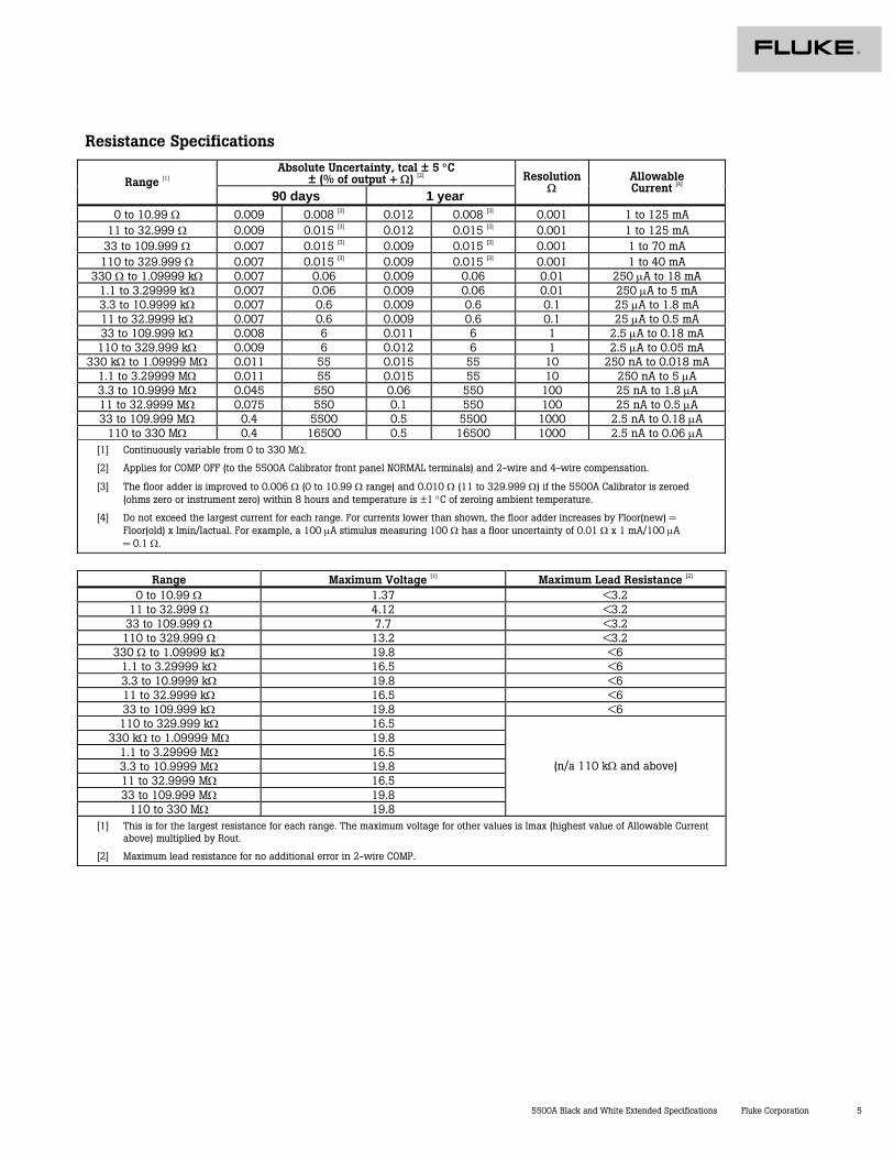
Resistance Specifications
Absolute Uncertainty, tcal ± 5 °C ± (% of output + Ω) [2] Range [1]
90 days 1 year
ResolutionΩ
Allowable Current [4]
0 to 10.99 Ω 0.009 0.008 [3] 0.012 0.008 [3] 0.001 1 to 125 mA 11 to 32.999 Ω 0.009 0.015 [3] 0.012 0.015 [3] 0.001 1 to 125 mA
33 to 109.999 Ω 0.007 0.015 [3] 0.009 0.015 [3] 0.001 1 to 70 mA 110 to 329.999 Ω 0.007 0.015 [3] 0.009 0.015 [3] 0.001 1 to 40 mA
330 Ω to 1.09999 kΩ 0.007 0.06 0.009 0.06 0.01 250 µA to 18 mA 1.1 to 3.29999 kΩ 0.007 0.06 0.009 0.06 0.01 250 µA to 5 mA 3.3 to 10.9999 kΩ 0.007 0.6 0.009 0.6 0.1 25 µA to 1.8 mA 11 to 32.9999 kΩ 0.007 0.6 0.009 0.6 0.1 25 µA to 0.5 mA 33 to 109.999 kΩ 0.008 6 0.011 6 1 2.5 µA to 0.18 mA 110 to 329.999 kΩ 0.009 6 0.012 6 1 2.5 µA to 0.05 mA
330 kΩ to 1.09999 MΩ 0.011 55 0.015 55 10 250 nA to 0.018 mA 1.1 to 3.29999 MΩ 0.011 55 0.015 55 10 250 nA to 5 µA 3.3 to 10.9999 MΩ 0.045 550 0.06 550 100 25 nA to 1.8 µA 11 to 32.9999 MΩ 0.075 550 0.1 550 100 25 nA to 0.5 µA 33 to 109.999 MΩ 0.4 5500 0.5 5500 1000 2.5 nA to 0.18 µA
110 to 330 MΩ 0.4 16500 0.5 16500 1000 2.5 nA to 0.06 µA [1] Continuously variable from 0 to 330 MΩ.
[2] Applies for COMP OFF (to the 5500A Calibrator front panel NORMAL terminals) and 2-wire and 4-wire compensation.
[3] The floor adder is improved to 0.006 Ω (0 to 10.99 Ω range) and 0.010 Ω (11 to 329.999 Ω) if the 5500A Calibrator is zeroed (ohms zero or instrument zero) within 8 hours and temperature is ±1 °C of zeroing ambient temperature.
[4] Do not exceed the largest current for each range. For currents lower than shown, the floor adder increases by Floor(new) = Floor(old) x Imin/Iactual. For example, a 100 µA stimulus measuring 100 Ω has a floor uncertainty of 0.01 Ω x 1 mA/100 µA = 0.1 Ω.
Range Maximum Voltage [1] Maximum Lead Resistance [2]
0 to 10.99 Ω 1.37 <3.2 11 to 32.999 Ω 4.12 <3.2
33 to 109.999 Ω 7.7 <3.2 110 to 329.999 Ω 13.2 <3.2
330 Ω to 1.09999 kΩ 19.8 <6 1.1 to 3.29999 kΩ 16.5 <6 3.3 to 10.9999 kΩ 19.8 <6 11 to 32.9999 kΩ 16.5 <6 33 to 109.999 kΩ 19.8 <6 110 to 329.999 kΩ 16.5
330 kΩ to 1.09999 MΩ 19.8 1.1 to 3.29999 MΩ 16.5 3.3 to 10.9999 MΩ 19.8 11 to 32.9999 MΩ 16.5 33 to 109.999 MΩ 19.8
110 to 330 MΩ 19.8
(n/a 110 kΩ and above)
[1] This is for the largest resistance for each range. The maximum voltage for other values is Imax (highest value of Allowable Current above) multiplied by Rout.
[2] Maximum lead resistance for no additional error in 2-wire COMP.
6 Fluke Corporation 5500A Black and White Extended Specifications
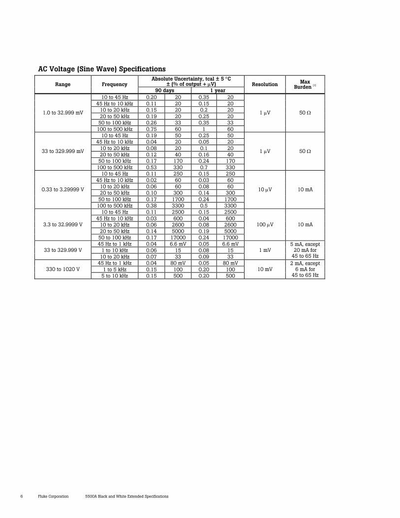
AC Voltage (Sine Wave) Specifications Absolute Uncertainty, tcal ± 5 °C
± (% of output + µV) Range Frequency 90 days 1 year
Resolution Max Burden [1]
10 to 45 Hz 0.20 20 0.35 20 45 Hz to 10 kHz 0.11 20 0.15 20
10 to 20 kHz 0.15 20 0.2 20 20 to 50 kHz 0.19 20 0.25 20
50 to 100 kHz 0.26 33 0.35 33
1.0 to 32.999 mV
100 to 500 kHz 0.75 60 1 60
1 µV 50 Ω
10 to 45 Hz 0.19 50 0.25 50 45 Hz to 10 kHz 0.04 20 0.05 20
10 to 20 kHz 0.08 20 0.1 20 20 to 50 kHz 0.12 40 0.16 40
50 to 100 kHz 0.17 170 0.24 170
33 to 329.999 mV
100 to 500 kHz 0.53 330 0.7 330
1 µV 50 Ω
10 to 45 Hz 0.11 250 0.15 250 45 Hz to 10 kHz 0.02 60 0.03 60
10 to 20 kHz 0.06 60 0.08 60 20 to 50 kHz 0.10 300 0.14 300
50 to 100 kHz 0.17 1700 0.24 1700
0.33 to 3.29999 V
100 to 500 kHz 0.38 3300 0.5 3300
10 µV 10 mA
10 to 45 Hz 0.11 2500 0.15 2500 45 Hz to 10 kHz 0.03 600 0.04 600
10 to 20 kHz 0.06 2600 0.08 2600 20 to 50 kHz 0.14 5000 0.19 5000
3.3 to 32.9999 V
50 to 100 kHz 0.17 17000 0.24 17000
100 µV 10 mA
45 Hz to 1 kHz 0.04 6.6 mV 0.05 6.6 mV 1 to 10 kHz 0.06 15 0.08 15 33 to 329.999 V
10 to 20 kHz 0.07 33 0.09 33 1 mV
5 mA, except 20 mA for
45 to 65 Hz 45 Hz to 1 kHz 0.04 80 mV 0.05 80 mV
1 to 5 kHz 0.15 100 0.20 100 330 to 1020 V 5 to 10 kHz 0.15 500 0.20 500
10 mV 2 mA, except
6 mA for 45 to 65 Hz
5500A Black and White Extended Specifications Fluke Corporation 7
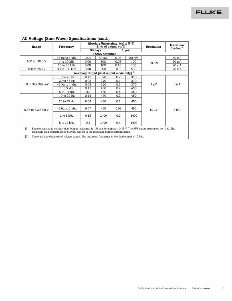
AC Voltage (Sine Wave) Specifications (cont.) Absolute Uncertainty, tcal ± 5 °C
± (% of output + µV) Range Frequency 90 days 1 year
Resolution Maximum Burden [1]
5725A Amplifier 45 Hz to 1 kHz 0.04 80 mV 0.05 80 mV 50 mA
1 to 20 kHz 0.06 100 0.08 100 70 mA 100 to 1020 V 20 to 30 kHz 0.08 100 0.10 100 70 mA
100 to 750 V 30 to 100 kHz 0.38 500 0.5 500
10 mV
70 mA Auxiliary Output [dual output mode only] [2]
10 to 20 Hz 0.15 370 0.2 370 20 to 45 Hz 0.08 370 0.1 370
45 Hz to 1 kHz 0.08 370 0.1 370 1 to 5 kHz 0.15 450 0.2 450
10 to 329.999 mV
5 to 10 kHz 0.3 450 0.4 450
1 µV 5 mA
10 to 20 Hz 0.15 450 0.2 450
20 to 45 Hz 0.08 450 0.1 450
45 Hz to 1 kHz 0.07 450 0.09 450
1 to 5 kHz 0.15 1400 0.2 1400
0.33 to 3.29999 V
5 to 10 kHz 0.3 1400 0.4 1400
10 µV 5 mA
[1] Remote sensing is not provided. Output resistance is < 5 mΩ for outputs ≥ 0.33 V. The AUX output resistance is < 1 Ω. The maximum load capacitance is 500 pF, subject to the maximum burden current limits.
[2] There are two channels of voltage output. The maximum frequency of the dual output is 10 kHz.
8 Fluke Corporation 5500A Black and White Extended Specifications
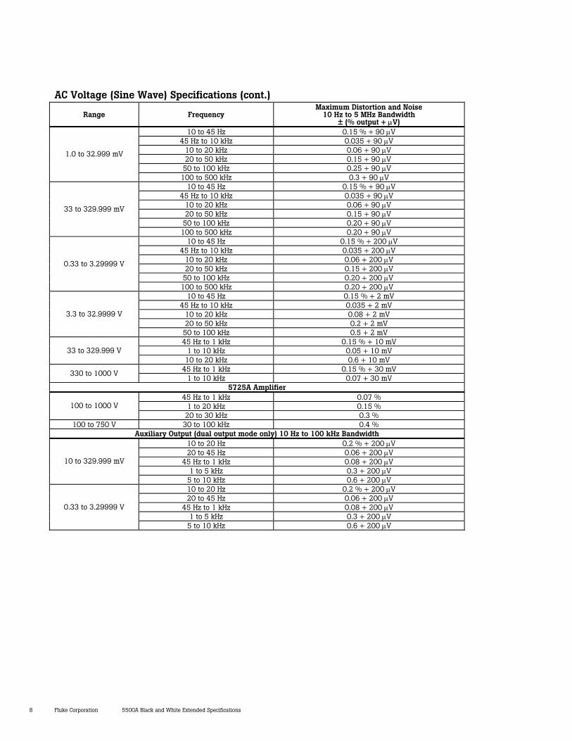
AC Voltage (Sine Wave) Specifications (cont.)
Range Frequency Maximum Distortion and Noise
10 Hz to 5 MHz Bandwidth ± (% output + µV)
10 to 45 Hz 0.15 % + 90 µV 45 Hz to 10 kHz 0.035 + 90 µV
10 to 20 kHz 0.06 + 90 µV 20 to 50 kHz 0.15 + 90 µV
50 to 100 kHz 0.25 + 90 µV
1.0 to 32.999 mV
100 to 500 kHz 0.3 + 90 µV 10 to 45 Hz 0.15 % + 90 µV
45 Hz to 10 kHz 0.035 + 90 µV 10 to 20 kHz 0.06 + 90 µV 20 to 50 kHz 0.15 + 90 µV
50 to 100 kHz 0.20 + 90 µV
33 to 329.999 mV
100 to 500 kHz 0.20 + 90 µV 10 to 45 Hz 0.15 % + 200 µV
45 Hz to 10 kHz 0.035 + 200 µV 10 to 20 kHz 0.06 + 200 µV 20 to 50 kHz 0.15 + 200 µV
50 to 100 kHz 0.20 + 200 µV
0.33 to 3.29999 V
100 to 500 kHz 0.20 + 200 µV 10 to 45 Hz 0.15 % + 2 mV
45 Hz to 10 kHz 0.035 + 2 mV 10 to 20 kHz 0.08 + 2 mV 20 to 50 kHz 0.2 + 2 mV
3.3 to 32.9999 V
50 to 100 kHz 0.5 + 2 mV 45 Hz to 1 kHz 0.15 % + 10 mV
1 to 10 kHz 0.05 + 10 mV 33 to 329.999 V 10 to 20 kHz 0.6 + 10 mV
45 Hz to 1 kHz 0.15 % + 30 mV 330 to 1000 V 1 to 10 kHz 0.07 + 30 mV
5725A Amplifier 45 Hz to 1 kHz 0.07 %
1 to 20 kHz 0.15 % 100 to 1000 V 20 to 30 kHz 0.3 %
100 to 750 V 30 to 100 kHz 0.4 % Auxiliary Output (dual output mode only) 10 Hz to 100 kHz Bandwidth
10 to 20 Hz 0.2 % + 200 µV 20 to 45 Hz 0.06 + 200 µV
45 Hz to 1 kHz 0.08 + 200 µV 1 to 5 kHz 0.3 + 200 µV
10 to 329.999 mV
5 to 10 kHz 0.6 + 200 µV 10 to 20 Hz 0.2 % + 200 µV 20 to 45 Hz 0.06 + 200 µV
45 Hz to 1 kHz 0.08 + 200 µV 1 to 5 kHz 0.3 + 200 µV
0.33 to 3.29999 V
5 to 10 kHz 0.6 + 200 µV
5500A Black and White Extended Specifications Fluke Corporation 9
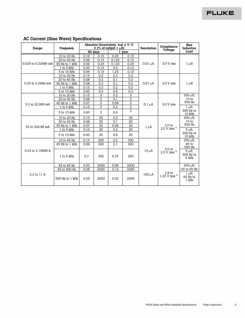
AC Current (Sine Wave) Specifications Absolute Uncertainty, tcal ± 5 °C
± (% of output + µA) Range Frequency 90 days 1 year
Resolution Compliance Voltage
Max Inductive
Load 10 to 20 Hz 0.19 0.15 0.25 0.15 20 to 45 Hz 0.09 0.15 0.125 0.15
45 Hz to 1 kHz 0.09 0.25 0.125 0.25 1 to 5 kHz 0.30 0.15 0.4 0.15
0.029 to 0.32999 mA
5 to 10 kHz 0.94 0.15 1.25 0.15
0.01 µA 3.0 V rms 1 µH
10 to 20 Hz 0.15 0.3 0.2 0.3 20 to 45 Hz 0.08 0.3 0.1 0.3
45 Hz to 1 kHz 0.08 0.3 0.1 0.3 1 to 5 kHz 0.15 0.3 0.2 0.3
0.33 to 3.2999 mA
5 to 10 kHz 0.45 0.3 0.6 0.3
0.01 µA 3.0 V rms 1 µH
10 to 20 Hz 0.15 3 0.2 3 20 to 45 Hz 0.08 3 0.1 3
45 Hz to 1 kHz 0.07 3 0.09 3
200 µH, 10 to
500 Hz
1 to 5 kHz 0.15 3 0.2 3 3.3 to 32.999 mA
5 to 10 kHz 0.45 3 0.6 3
0.1 µA 3.0 V rms 1 µH,
500 Hz to 10 kHz
10 to 20 Hz 0.15 30 0.2 30 20 to 45 Hz 0.08 30 0.1 30
45 Hz to 1 kHz 0.07 30 0.09 30
200 µH, 10 to
500 Hz
1 to 5 kHz 0.15 30 0.2 30 33 to 329.99 mA
5 to 10 kHz 0.45 30 0.6 30
1 µA 3.0 to 2.0 V rms [1] 5 µH,
500 Hz to 10 kHz
10 to 45 Hz 0.15 300 0.2 300 45 Hz to 1 kHz 0.08 300 0.1 300
200 µH, 45 to
500 Hz 0.33 to 2.19999 A
1 to 5 kHz 0.7 300 0.75 300
10 µA 3.0 to 2.0 V rms [2] 5 µH,
500 Hz to 5 kHz
45 to 65 Hz 0.05 2000 0.06 2000 65 to 500 Hz 0.08 2000 0.10 2000
200 µH, 45 to 65 Hz
2.2 to 11 A 500 Hz to 1 kHz 0.25 2000 0.33 2000
100 µA 2.8 to 1.25 V rms [3]
1 µH, 65 Hz to
1 kHz
10 Fluke Corporation 5500A Black and White Extended Specifications
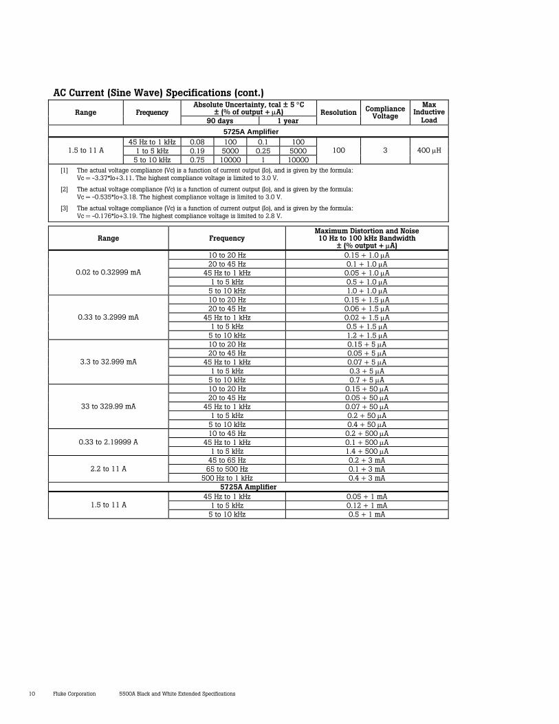
AC Current (Sine Wave) Specifications (cont.) Absolute Uncertainty, tcal ± 5 °C
± (% of output + µA) Range Frequency 90 days 1 year
Resolution Compliance Voltage
Max Inductive
Load
5725A Amplifier 45 Hz to 1 kHz 0.08 100 0.1 100
1 to 5 kHz 0.19 5000 0.25 5000 1.5 to 11 A 5 to 10 kHz 0.75 10000 1 10000
100 3 400 µH
[1] The actual voltage compliance (Vc) is a function of current output (Io), and is given by the formula: Vc = -3.37*Io+3.11. The highest compliance voltage is limited to 3.0 V.
[2] The actual voltage compliance (Vc) is a function of current output (Io), and is given by the formula: Vc = -0.535*Io+3.18. The highest compliance voltage is limited to 3.0 V.
[3] The actual voltage compliance (Vc) is a function of current output (Io), and is given by the formula: Vc = -0.176*Io+3.19. The highest compliance voltage is limited to 2.8 V.
Range Frequency Maximum Distortion and Noise 10 Hz to 100 kHz Bandwidth
± (% output + µA) 10 to 20 Hz 0.15 + 1.0 µA 20 to 45 Hz 0.1 + 1.0 µA
45 Hz to 1 kHz 0.05 + 1.0 µA 1 to 5 kHz 0.5 + 1.0 µA
0.02 to 0.32999 mA
5 to 10 kHz 1.0 + 1.0 µA 10 to 20 Hz 0.15 + 1.5 µA 20 to 45 Hz 0.06 + 1.5 µA
45 Hz to 1 kHz 0.02 + 1.5 µA 1 to 5 kHz 0.5 + 1.5 µA
0.33 to 3.2999 mA
5 to 10 kHz 1.2 + 1.5 µA 10 to 20 Hz 0.15 + 5 µA 20 to 45 Hz 0.05 + 5 µA
45 Hz to 1 kHz 0.07 + 5 µA 1 to 5 kHz 0.3 + 5 µA
3.3 to 32.999 mA
5 to 10 kHz 0.7 + 5 µA 10 to 20 Hz 0.15 + 50 µA 20 to 45 Hz 0.05 + 50 µA
45 Hz to 1 kHz 0.07 + 50 µA 1 to 5 kHz 0.2 + 50 µA
33 to 329.99 mA
5 to 10 kHz 0.4 + 50 µA 10 to 45 Hz 0.2 + 500 µA
45 Hz to 1 kHz 0.1 + 500 µA 0.33 to 2.19999 A 1 to 5 kHz 1.4 + 500 µA
45 to 65 Hz 0.2 + 3 mA 65 to 500 Hz 0.1 + 3 mA 2.2 to 11 A
500 Hz to 1 kHz 0.4 + 3 mA 5725A Amplifier
45 Hz to 1 kHz 0.05 + 1 mA 1 to 5 kHz 0.12 + 1 mA 1.5 to 11 A
5 to 10 kHz 0.5 + 1 mA
5500A Black and White Extended Specifications Fluke Corporation 11
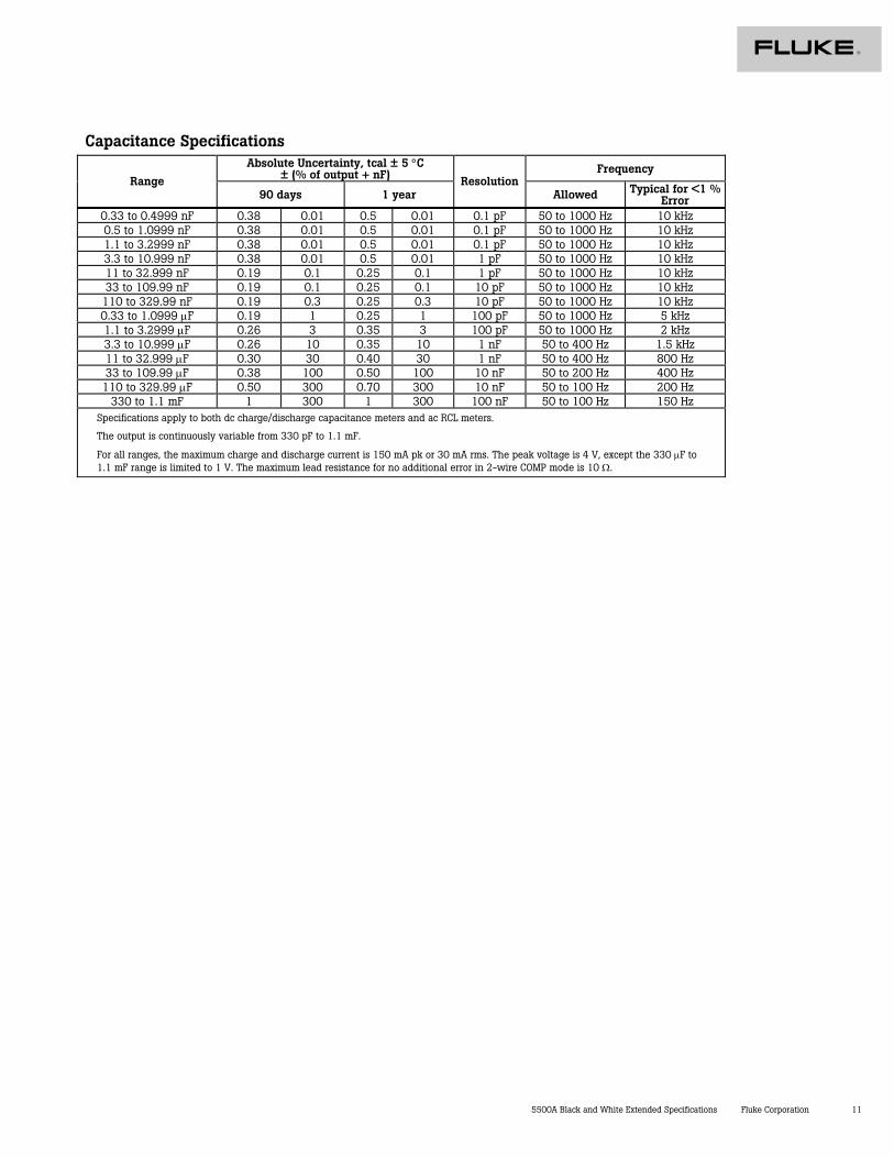
Capacitance Specifications Absolute Uncertainty, tcal ± 5 °C
± (% of output + nF) Frequency Range
90 days 1 year Resolution
Allowed Typical for <1 % Error
0.33 to 0.4999 nF 0.38 0.01 0.5 0.01 0.1 pF 50 to 1000 Hz 10 kHz 0.5 to 1.0999 nF 0.38 0.01 0.5 0.01 0.1 pF 50 to 1000 Hz 10 kHz 1.1 to 3.2999 nF 0.38 0.01 0.5 0.01 0.1 pF 50 to 1000 Hz 10 kHz 3.3 to 10.999 nF 0.38 0.01 0.5 0.01 1 pF 50 to 1000 Hz 10 kHz 11 to 32.999 nF 0.19 0.1 0.25 0.1 1 pF 50 to 1000 Hz 10 kHz 33 to 109.99 nF 0.19 0.1 0.25 0.1 10 pF 50 to 1000 Hz 10 kHz
110 to 329.99 nF 0.19 0.3 0.25 0.3 10 pF 50 to 1000 Hz 10 kHz 0.33 to 1.0999 µF 0.19 1 0.25 1 100 pF 50 to 1000 Hz 5 kHz 1.1 to 3.2999 µF 0.26 3 0.35 3 100 pF 50 to 1000 Hz 2 kHz 3.3 to 10.999 µF 0.26 10 0.35 10 1 nF 50 to 400 Hz 1.5 kHz 11 to 32.999 µF 0.30 30 0.40 30 1 nF 50 to 400 Hz 800 Hz 33 to 109.99 µF 0.38 100 0.50 100 10 nF 50 to 200 Hz 400 Hz 110 to 329.99 µF 0.50 300 0.70 300 10 nF 50 to 100 Hz 200 Hz
330 to 1.1 mF 1 300 1 300 100 nF 50 to 100 Hz 150 Hz Specifications apply to both dc charge/discharge capacitance meters and ac RCL meters.
The output is continuously variable from 330 pF to 1.1 mF.
For all ranges, the maximum charge and discharge current is 150 mA pk or 30 mA rms. The peak voltage is 4 V, except the 330 µF to 1.1 mF range is limited to 1 V. The maximum lead resistance for no additional error in 2-wire COMP mode is 10 Ω.
12 Fluke Corporation 5500A Black and White Extended Specifications
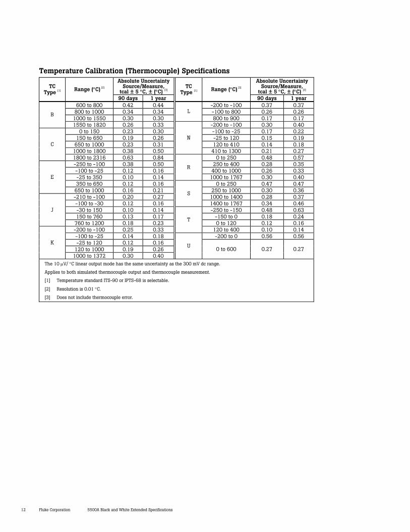
Temperature Calibration (Thermocouple) Specifications Absolute Uncertainty
Source/Measure, tcal ± 5 °C, ± (°C) [3]
Absolute Uncertainty Source/Measure,
tcal ± 5 °C, ± (°C) [3] TC
Type [1] Range (°C) [2]
90 days 1 year
TC Type [1] Range (°C) [2]
90 days 1 year 600 to 800 0.42 0.44 -200 to -100 0.37 0.37
800 to 1000 0.34 0.34 -100 to 800 0.26 0.26 1000 to 1550 0.30 0.30
L 800 to 900 0.17 0.17
B
1550 to 1820 0.26 0.33 -200 to -100 0.30 0.40 0 to 150 0.23 0.30 -100 to -25 0.17 0.22
150 to 650 0.19 0.26 -25 to 120 0.15 0.19 650 to 1000 0.23 0.31 120 to 410 0.14 0.18
1000 to 1800 0.38 0.50
N
410 to 1300 0.21 0.27 C
1800 to 2316 0.63 0.84 0 to 250 0.48 0.57 -250 to -100 0.38 0.50 250 to 400 0.28 0.35 -100 to -25 0.12 0.16 400 to 1000 0.26 0.33 -25 to 350 0.10 0.14
R
1000 to 1767 0.30 0.40 350 to 650 0.12 0.16 0 to 250 0.47 0.47
E
650 to 1000 0.16 0.21 250 to 1000 0.30 0.36 -210 to -100 0.20 0.27 1000 to 1400 0.28 0.37 -100 to -30 0.12 0.16
S
1400 to 1767 0.34 0.46 -30 to 150 0.10 0.14 -250 to -150 0.48 0.63 150 to 760 0.13 0.17 -150 to 0 0.18 0.24
J
760 to 1200 0.18 0.23 0 to 120 0.12 0.16 -200 to -100 0.25 0.33
T
120 to 400 0.10 0.14 -100 to -25 0.14 0.18 -200 to 0 0.56 0.56 -25 to 120 0.12 0.16
120 to 1000 0.19 0.26 K
1000 to 1372 0.30 0.40
U 0 to 600 0.27 0.27
The 10 µV/ °C linear output mode has the same uncertainty as the 300 mV dc range.
Applies to both simulated thermocouple output and thermocouple measurement.
[1] Temperature standard ITS-90 or IPTS-68 is selectable.
[2] Resolution is 0.01 °C.
[3] Does not include thermocouple error.
5500A Black and White Extended Specifications Fluke Corporation 13
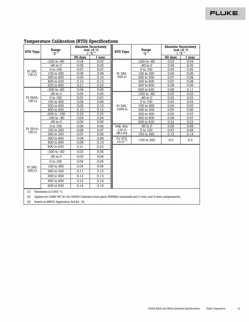
Temperature Calibration (RTD) Specifications Absolute Uncertainty
tcal ±5 °C ± °C [2]
Absolute Uncertainty tcal ±5 °C
± °C [2] RTD Type Range °C [1]
90 days 1 year
RTD Type Range °C [1]
90 days 1 year -200 to -80 0.04 0.05 -200 to -80 0.03 0.04
-80 to 0 0.05 0.05 -80 to 0 0.04 0.05 0 to 100 0.07 0.07 0 to 100 0.05 0.05
100 to 300 0.08 0.09 100 to 260 0.06 0.06 300 to 400 0.09 0.10 260 to 300 0.07 0.08 400 to 630 0.10 0.12 300 to 400 0.07 0.08
Pt 395, 100 Ω
630 to 800 0.21 0.23 400 to 600 0.08 0.09 -200 to -80 0.04 0.05
Pt 385, 500 Ω
600 to 630 0.09 0.11 -80 to 0 0.05 0.05 -200 to -80 0.03 0.03 0 to 100 0.07 0.07 -80 to 0 0.03 0.03
100 to 300 0.08 0.09 0 to 100 0.03 0.04 300 to 400 0.09 0.10 100 to 260 0.04 0.05
Pt 3926, 100 Ω
400 to 630 0.10 0.12 260 to 300 0.05 0.06 -200 to -190 0.25 0.25 300 to 400 0.05 0.07 -190 to -80 0.04 0.04 400 to 600 0.06 0.07
-80 to 0 0.05 0.05
Pt 385, 1000 Ω
600 to 630 0.22 0.23 0 to 100 0.06 0.06 -80 to 0 0.06 0.08
100 to 260 0.06 0.07 0 to 100 0.07 0.08 260 to 300 0.07 0.08
PtNi 385, 120 Ω (Ni120) 100 to 260 0.13 0.14
300 to 400 0.08 0.09 400 to 600 0.08 0.10
Cu 427, 10 Ω [3] -100 to 260 0.3 0.3
Pt 3916, 100 Ω
600 to 630 0.21 0.23
-200 to -80 0.03 0.04 -80 to 0 0.03 0.04 0 to 100 0.04 0.04
100 to 260 0.04 0.05 260 to 300 0.11 0.12 300 to 400 0.12 0.13 400 to 600 0.12 0.14
Pt 385, 200 Ω
600 to 630 0.14 0.16
[1] Resolution is 0.003 °C.
[2] Applies for COMP OFF (to the 5500A Calibrator front panel NORMAL terminals) and 2-wire and 4-wire compensation.
[3] Based on MINCO Application Aid No. 18.
14 Fluke Corporation 5500A Black and White Extended Specifications
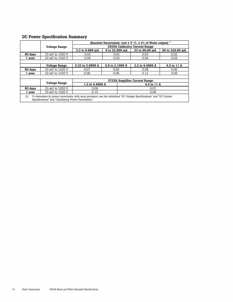
DC Power Specification Summary Absolute Uncertainty, tcal ± 5 °C, ± (% of Watts output) [1]
5500A Calibrator Current Range
Voltage Range 3.3 to 8.999 mA 9 to 32.999 mA 33 to 89.99 mA 90 to 329.99 mA
90 days 33 mV to 1020 V 0.03 0.02 0.03 0.02 1 year 33 mV to 1020 V 0.04 0.03 0.04 0.03
Voltage Range 0.33 to 0.8999 A 0.9 to 2.1999 A 2.2 to 4.4999 A 4.5 to 11 A
90 days 33 mV to 1020 V 0.07 0.05 0.08 0.06 1 year 33 mV to 1020 V 0.08 0.06 0.12 0.09
5725A Amplifier Current Range
Voltage Range 1.5 to 4.4999 A 4.5 to 11 A 90 days 33 mV to 1020 V 0.09 0.07 1 year 33 mV to 1020 V 0.10 0.08 [1] To determine dc power uncertainty with more precision, see the individual “DC Voltage Specifications” and “DC Current
Specifications” and “Calculating Power Uncertainty.”
5500A Black and White Extended Specifications Fluke Corporation 15
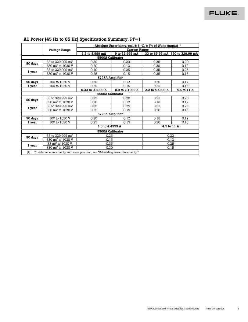
AC Power (45 Hz to 65 Hz) Specification Summary, PF=1 Absolute Uncertainty, tcal ± 5 °C, ± (% of Watts output) [1]
Current Range
Voltage Range 3.3 to 8.999 mA 9 to 32.999 mA 33 to 89.99 mA 90 to 329.99 mA
5500A Calibrator 33 to 329.999 mV 0.30 0.20 0.25 0.20 90 days 330 mV to 1020 V 0.20 0.12 0.20 0.12 33 to 329.999 mV 0.40 0.25 0.35 0.25 1 year 330 mV to 1020 V 0.25 0.15 0.25 0.15
5725A Amplifier 90 days 100 to 1020 V 0.20 0.12 0.20 0.12 1 year 100 to 1020 V 0.25 0.15 0.25 0.15
0.33 to 0.8999 A 0.9 to 2.1999 A 2.2 to 4.4999 A 4.5 to 11 A 5500A Calibrator
33 to 329.999 mV 0.25 0.20 0.25 0.20 90 days 330 mV to 1020 V 0.20 0.12 0.18 0.12 33 to 329.999 mV 0.35 0.25 0.35 0.25 1 year 330 mV to 1020 V 0.25 0.15 0.20 0.15
5725A Amplifier 90 days 100 to 1020 V 0.20 0.12 0.18 0.12 1 year 100 to 1020 V 0.25 0.15 0.20 0.15
1.5 to 4.4999 A 4.5 to 11 A
5500A Calibrator 33 to 329.999 mV 0.25 0.20 90 days 330 mV to 1020 V 0.15 0.12 33 mV to 1020 V 0.35 0.25 1 year
330 mV to 1020 V 0.20 0.15 [1] To determine uncertainty with more precision, see “Calculating Power Uncertainty.”
16 Fluke Corporation 5500A Black and White Extended Specifications
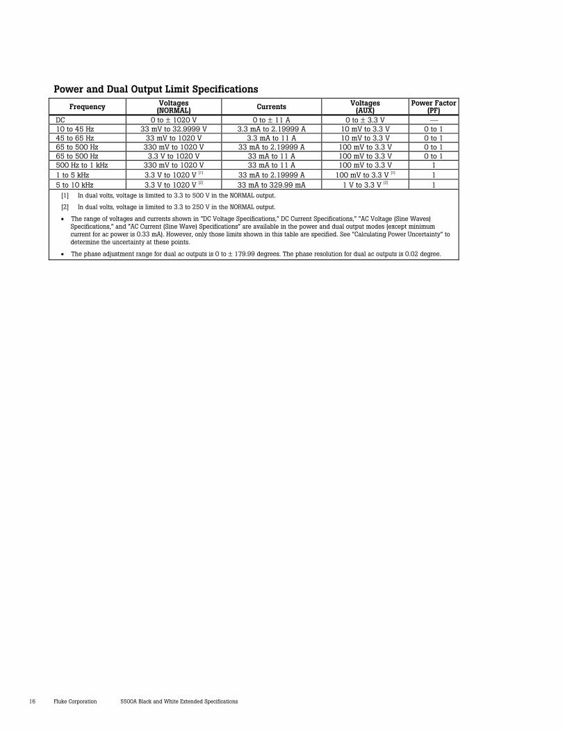
Power and Dual Output Limit Specifications
Frequency Voltages (NORMAL) Currents Voltages
(AUX) Power Factor
(PF) DC 0 to ± 1020 V 0 to ± 11 A 0 to ± 3.3 V 10 to 45 Hz 33 mV to 32.9999 V 3.3 mA to 2.19999 A 10 mV to 3.3 V 0 to 1 45 to 65 Hz 33 mV to 1020 V 3.3 mA to 11 A 10 mV to 3.3 V 0 to 1 65 to 500 Hz 330 mV to 1020 V 33 mA to 2.19999 A 100 mV to 3.3 V 0 to 1 65 to 500 Hz 3.3 V to 1020 V 33 mA to 11 A 100 mV to 3.3 V 0 to 1 500 Hz to 1 kHz 330 mV to 1020 V 33 mA to 11 A 100 mV to 3.3 V 1 1 to 5 kHz 3.3 V to 1020 V [1] 33 mA to 2.19999 A 100 mV to 3.3 V [1] 1 5 to 10 kHz 3.3 V to 1020 V [2] 33 mA to 329.99 mA 1 V to 3.3 V [2] 1
[1] In dual volts, voltage is limited to 3.3 to 500 V in the NORMAL output.
[2] In dual volts, voltage is limited to 3.3 to 250 V in the NORMAL output.
• The range of voltages and currents shown in “DC Voltage Specifications,” DC Current Specifications,” “AC Voltage (Sine Waves) Specifications,” and “AC Current (Sine Wave) Specifications” are available in the power and dual output modes (except minimum current for ac power is 0.33 mA). However, only those limits shown in this table are specified. See “Calculating Power Uncertainty” to determine the uncertainty at these points.
• The phase adjustment range for dual ac outputs is 0 to ± 179.99 degrees. The phase resolution for dual ac outputs is 0.02 degree.
5500A Black and White Extended Specifications Fluke Corporation 17
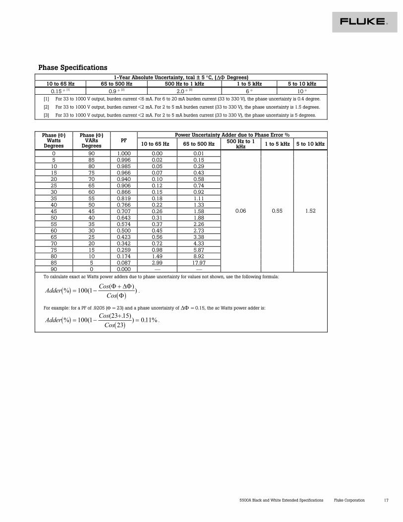
Phase Specifications 1-Year Absolute Uncertainty, tcal ± 5 °C, (∆Φ Degrees)
10 to 65 Hz 65 to 500 Hz 500 Hz to 1 kHz 1 to 5 kHz 5 to 10 kHz 0.15 ° [1] 0.9 ° [2] 2.0 ° [3] 6 ° 10 °
[1] For 33 to 1000 V output, burden current <6 mA. For 6 to 20 mA burden current (33 to 330 V), the phase uncertainty is 0.4 degree.
[2] For 33 to 1000 V output, burden current <2 mA. For 2 to 5 mA burden current (33 to 330 V), the phase uncertainty is 1.5 degrees.
[3] For 33 to 1000 V output, burden current <2 mA. For 2 to 5 mA burden current (33 to 330 V), the phase uncertainty is 5 degrees.
Power Uncertainty Adder due to Phase Error % Phase (Φ) Watts
Degrees
Phase (Φ) VARs
Degrees PF
10 to 65 Hz 65 to 500 Hz 500 Hz to 1 kHz 1 to 5 kHz 5 to 10 kHz
0 90 1.000 0.00 0.01 5 85 0.996 0.02 0.15
10 80 0.985 0.05 0.29 15 75 0.966 0.07 0.43 20 70 0.940 0.10 0.58 25 65 0.906 0.12 0.74 30 60 0.866 0.15 0.92 35 55 0.819 0.18 1.11 40 50 0.766 0.22 1.33 45 45 0.707 0.26 1.58 50 40 0.643 0.31 1.88 55 35 0.574 0.37 2.26 60 30 0.500 0.45 2.73 65 25 0.423 0.56 3.38 70 20 0.342 0.72 4.33 75 15 0.259 0.98 5.87 80 10 0.174 1.49 8.92 85 5 0.087 2.99 17.97 90 0 0.000
0.06 0.55 1.52
To calculate exact ac Watts power adders due to phase uncertainty for values not shown, use the following formula:
( )( )
Adder CosCos
% ( ( )= −
+100 1 Φ ∆ΦΦ
) .
For example: for a PF of .9205 (Φ = 23) and a phase uncertainty of ∆Φ = 0.15, the ac Watts power adder is:
( )( )
Adder CosCos
% ( (23 )= −
+=100 1 15
230 11%. ) . .
18 Fluke Corporation 5500A Black and White Extended Specifications
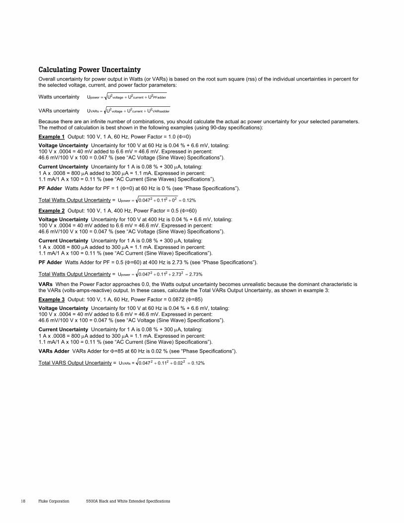
Calculating Power Uncertainty Overall uncertainty for power output in Watts (or VARs) is based on the root sum square (rss) of the individual uncertainties in percent for the selected voltage, current, and power factor parameters:
Watts uncertainty PFadder2current2voltage2power UUUU ++=
VARs uncertainty VARsadder2current2voltage2VARs UUUU ++=
Because there are an infinite number of combinations, you should calculate the actual ac power uncertainty for your selected parameters. The method of calculation is best shown in the following examples (using 90-day specifications):
Example 1 Output: 100 V, 1 A, 60 Hz, Power Factor = 1.0 (Φ=0) Voltage Uncertainty Uncertainty for 100 V at 60 Hz is 0.04 % + 6.6 mV, totaling: 100 V x .0004 = 40 mV added to 6.6 mV = 46.6 mV. Expressed in percent: 46.6 mV/100 V x 100 = 0.047 % (see “AC Voltage (Sine Wave) Specifications”).
Current Uncertainty Uncertainty for 1 A is 0.08 % + 300 µA, totaling: 1 A x .0008 = 800 µA added to 300 µA = 1.1 mA. Expressed in percent: 1.1 mA/1 A x 100 = 0.11 % (see “AC Current (Sine Waves) Specifications”).
PF Adder Watts Adder for PF = 1 (Φ=0) at 60 Hz is 0 % (see “Phase Specifications”).
Total Watts Output Uncertainty = %12.0011.0047.0U 222power =++=
Example 2 Output: 100 V, 1 A, 400 Hz, Power Factor = 0.5 (Φ=60) Voltage Uncertainty Uncertainty for 100 V at 400 Hz is 0.04 % + 6.6 mV, totaling: 100 V x .0004 = 40 mV added to 6.6 mV = 46.6 mV. Expressed in percent: 46.6 mV/100 V x 100 = 0.047 % (see “AC Voltage (Sine Wave) Specifications”).
Current Uncertainty Uncertainty for 1 A is 0.08 % + 300 µA, totaling: 1 A x .0008 = 800 µA added to 300 µA = 1.1 mA. Expressed in percent: 1.1 mA/1 A x 100 = 0.11 % (see “AC Current (Sine Wave) Specifications”).
PF Adder Watts Adder for PF = 0.5 (Φ=60) at 400 Hz is 2.73 % (see “Phase Specifications”).
Total Watts Output Uncertainty = %73.273.211.0047.0U 222power =++=
VARs When the Power Factor approaches 0.0, the Watts output uncertainty becomes unrealistic because the dominant characteristic is the VARs (volts-amps-reactive) output. In these cases, calculate the Total VARs Output Uncertainty, as shown in example 3:
Example 3 Output: 100 V, 1 A, 60 Hz, Power Factor = 0.0872 (Φ=85) Voltage Uncertainty Uncertainty for 100 V at 60 Hz is 0.04 % + 6.6 mV, totaling: 100 V x .0004 = 40 mV added to 6.6 mV = 46.6 mV. Expressed in percent: 46.6 mV/100 V x 100 = 0.047 % (see “AC Voltage (Sine Wave) Specifications”).
Current Uncertainty Uncertainty for 1 A is 0.08 % + 300 µA, totaling: 1 A x .0008 = 800 µA added to 300 µA = 1.1 mA. Expressed in percent: 1.1 mA/1 A x 100 = 0.11 % (see “AC Current (Sine Wave) Specifications”).
VARs Adder VARs Adder for Φ=85 at 60 Hz is 0.02 % (see “Phase Specifications”).
Total VARS Output Uncertainty = %12.002.011.0047.0=U 222VARs =++
5500A Black and White Extended Specifications Fluke Corporation 19
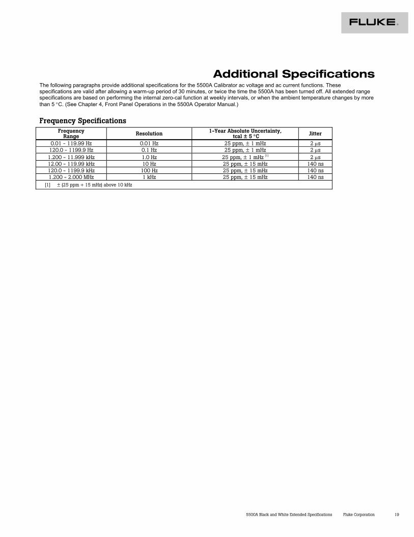
Additional Specifications The following paragraphs provide additional specifications for the 5500A Calibrator ac voltage and ac current functions. These specifications are valid after allowing a warm-up period of 30 minutes, or twice the time the 5500A has been turned off. All extended range specifications are based on performing the internal zero-cal function at weekly intervals, or when the ambient temperature changes by more than 5 °C. (See Chapter 4, Front Panel Operations in the 5500A Operator Manual.)
Frequency Specifications Frequency
Range Resolution 1-Year Absolute Uncertainty, tcal ± 5 °C Jitter
0.01 - 119.99 Hz 0.01 Hz 25 ppm, ± 1 mHz 2 µs 120.0 - 1199.9 Hz 0.1 Hz 25 ppm, ± 1 mHz 2 µs 1.200 - 11.999 kHz 1.0 Hz 25 ppm, ± 1 mHz [1] 2 µs 12.00 - 119.99 kHz 10 Hz 25 ppm, ± 15 mHz 140 ns 120.0 - 1199.9 kHz 100 Hz 25 ppm, ± 15 mHz 140 ns 1.200 - 2.000 MHz 1 kHz 25 ppm, ± 15 mHz 140 ns
[1] ± (25 ppm + 15 mHz) above 10 kHz
20 Fluke Corporation 5500A Black and White Extended Specifications
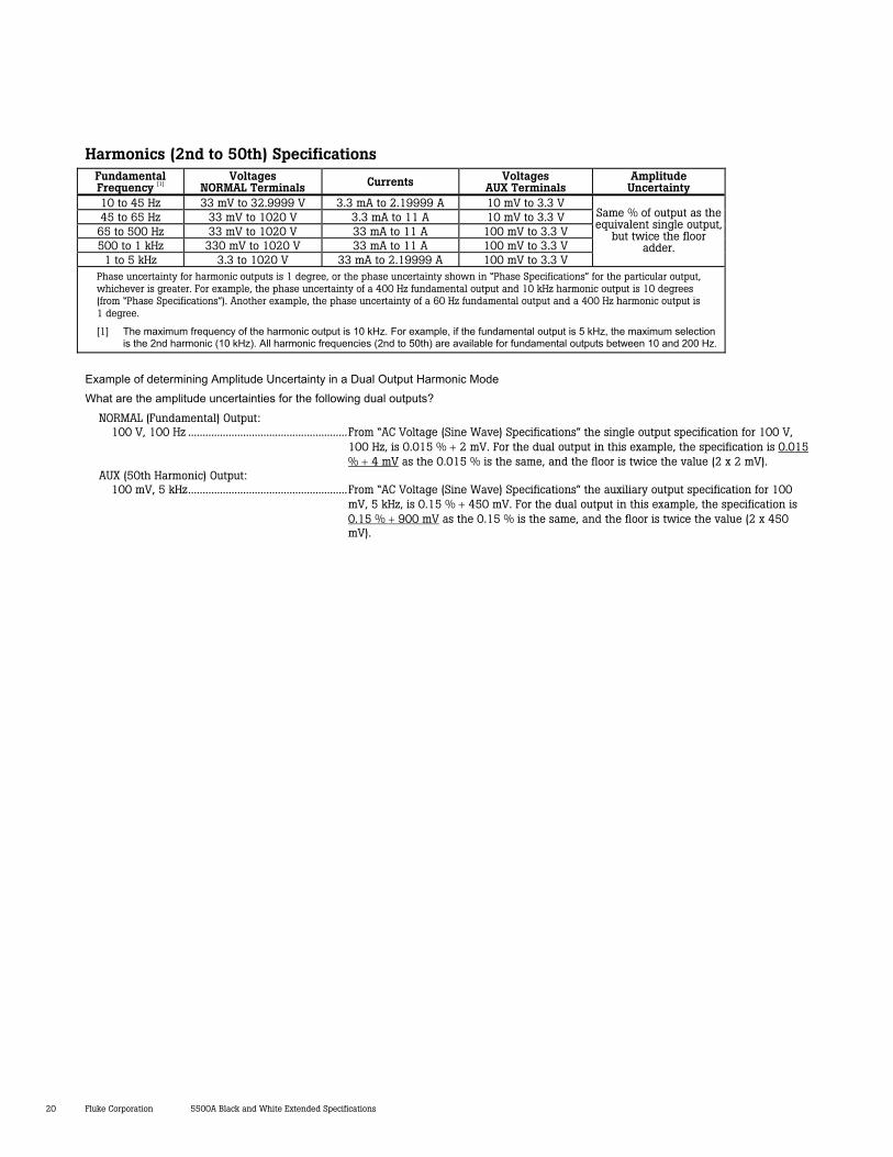
Harmonics (2nd to 50th) Specifications Fundamental Frequency [1]
Voltages NORMAL Terminals Currents Voltages
AUX Terminals Amplitude Uncertainty
10 to 45 Hz 33 mV to 32.9999 V 3.3 mA to 2.19999 A 10 mV to 3.3 V 45 to 65 Hz 33 mV to 1020 V 3.3 mA to 11 A 10 mV to 3.3 V
65 to 500 Hz 33 mV to 1020 V 33 mA to 11 A 100 mV to 3.3 V 500 to 1 kHz 330 mV to 1020 V 33 mA to 11 A 100 mV to 3.3 V
1 to 5 kHz 3.3 to 1020 V 33 mA to 2.19999 A 100 mV to 3.3 V
Same % of output as the equivalent single output,
but twice the floor adder.
Phase uncertainty for harmonic outputs is 1 degree, or the phase uncertainty shown in “Phase Specifications” for the particular output, whichever is greater. For example, the phase uncertainty of a 400 Hz fundamental output and 10 kHz harmonic output is 10 degrees (from “Phase Specifications”). Another example, the phase uncertainty of a 60 Hz fundamental output and a 400 Hz harmonic output is 1 degree.
[1] The maximum frequency of the harmonic output is 10 kHz. For example, if the fundamental output is 5 kHz, the maximum selection is the 2nd harmonic (10 kHz). All harmonic frequencies (2nd to 50th) are available for fundamental outputs between 10 and 200 Hz.
Example of determining Amplitude Uncertainty in a Dual Output Harmonic Mode What are the amplitude uncertainties for the following dual outputs?
NORMAL (Fundamental) Output: 100 V, 100 Hz .......................................................From “AC Voltage (Sine Wave) Specifications” the single output specification for 100 V,
100 Hz, is 0.015 % + 2 mV. For the dual output in this example, the specification is 0.015 % + 4 mV as the 0.015 % is the same, and the floor is twice the value (2 x 2 mV).
AUX (50th Harmonic) Output: 100 mV, 5 kHz.......................................................From “AC Voltage (Sine Wave) Specifications” the auxiliary output specification for 100
mV, 5 kHz, is 0.15 % + 450 mV. For the dual output in this example, the specification is 0.15 % + 900 mV as the 0.15 % is the same, and the floor is twice the value (2 x 450 mV).
5500A Black and White Extended Specifications Fluke Corporation 21
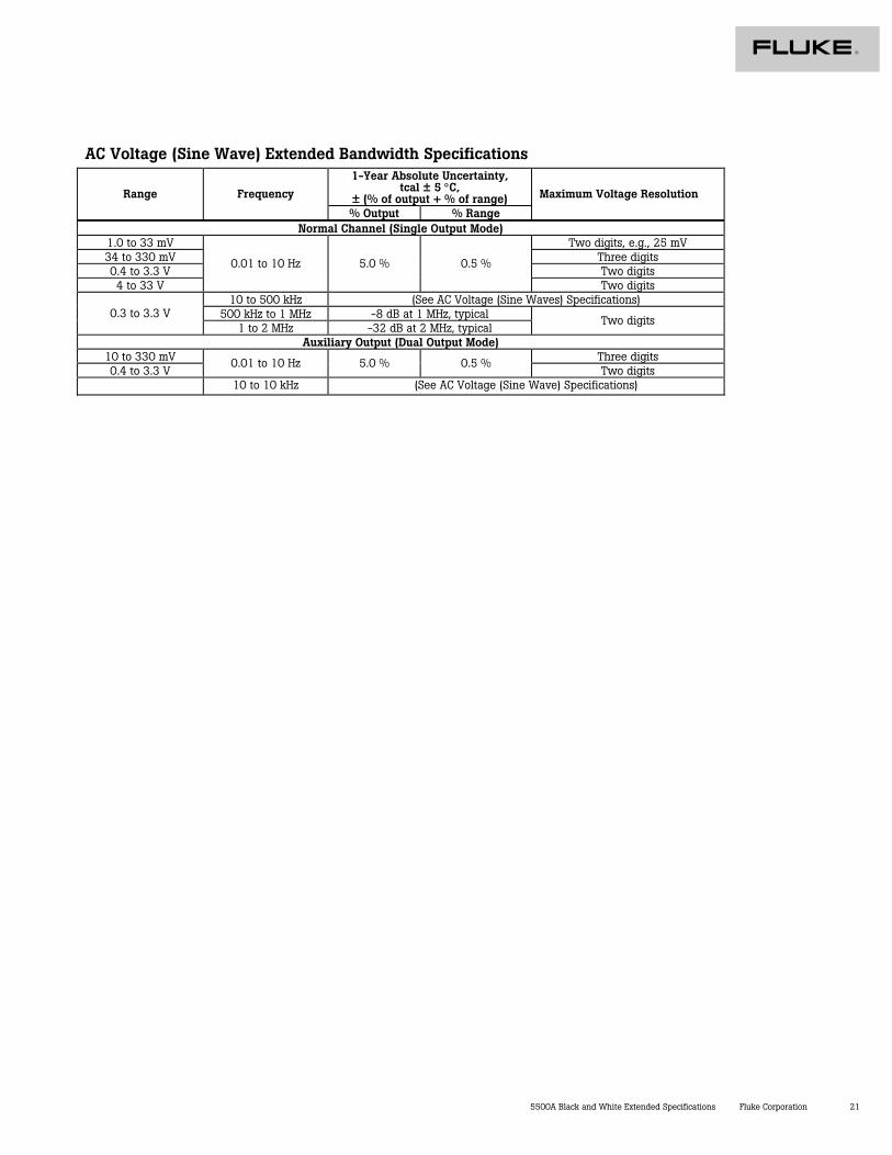
AC Voltage (Sine Wave) Extended Bandwidth Specifications 1-Year Absolute Uncertainty,
tcal ± 5 °C, ± (% of output + % of range) Range Frequency
% Output % Range
Maximum Voltage Resolution
Normal Channel (Single Output Mode) 1.0 to 33 mV Two digits, e.g., 25 mV 34 to 330 mV Three digits 0.4 to 3.3 V Two digits 4 to 33 V
0.01 to 10 Hz 5.0 % 0.5 %
Two digits 10 to 500 kHz (See AC Voltage (Sine Waves) Specifications)
500 kHz to 1 MHz -8 dB at 1 MHz, typical 0.3 to 3.3 V 1 to 2 MHz -32 dB at 2 MHz, typical
Two digits
Auxiliary Output (Dual Output Mode) 10 to 330 mV Three digits 0.4 to 3.3 V
0.01 to 10 Hz 5.0 % 0.5 % Two digits
10 to 10 kHz (See AC Voltage (Sine Wave) Specifications)
22 Fluke Corporation 5500A Black and White Extended Specifications
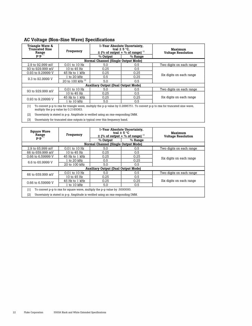
AC Voltage (Non-Sine Wave) Specifications 1-Year Absolute Uncertainty,
tcal ± 5 °C, ± (% of output + % of range) [2]
Triangle Wave & Truncated Sine
Range p-p [1]
Frequency
% Output % Range
Maximum Voltage Resolution
Normal Channel (Single Output Mode) 2.9 to 92.999 mV 0.01 to 10 Hz 5.0 0.5 Two digits on each range 93 to 929.999 mV 10 to 45 Hz 0.25 0.5 0.93 to 9.29999 V 45 Hz to 1 kHz 0.25 0.25
1 to 20 kHz 0.5 0.25 9.3 to 92.9999 V
20 to 100 kHz [3] 5.0 0.5
Six digits on each range
Auxiliary Output (Dual Output Mode) 0.01 to 10 Hz 5.0 0.5 Two digits on each range 93 to 929.999 mV 10 to 45 Hz 0.25 0.5
45 Hz to 1 kHz 0.25 0.25 0.93 to 9.29999 V 1 to 10 kHz 5.0 0.5
Six digits on each range
[1] To convert p-p to rms for triangle wave, multiply the p-p value by 0.2886751. To convert p-p to rms for truncated sine wave, multiply the p-p value by 0.2165063.
[2] Uncertainty is stated in p-p. Amplitude is verified using an rms-responding DMM.
[3] Uncertainty for truncated sine outputs is typical over this frequency band.
1-Year Absolute Uncertainty,
tcal ± 5 °C ± (% of output + % of range) [2]
Square Wave Range p-p [1]
Frequency
% Output % Range
Maximum Voltage Resolution
Normal Channel (Single Output Mode) 2.9 to 65.999 mV 0.01 to 10 Hz 5.0 0.5 Two digits on each range 66 to 659.999 mV 10 to 45 Hz 0.25 0.5 0.66 to 6.59999 V 45 Hz to 1 kHz 0.25 0.25
1 to 20 kHz 0.5 0.25 6.6 to 65.9999 V 20 to 100 kHz 5.0 0.5
Six digits on each range
Auxiliary Output (Dual Output Mode) 0.01 to 10 Hz 5.0 0.5 Two digits on each range 66 to 659.999 mV 10 to 45 Hz 0.25 0.5
45 Hz to 1 kHz 0.25 0.25 0.66 to 6.59999 V 1 to 10 kHz 5.0 0.5
Six digits on each range
[1] To convert p-p to rms for square wave, multiply the p-p value by .5000000.
[2] Uncertainty is stated in p-p. Amplitude is verified using an rms-responding DMM.
5500A Black and White Extended Specifications Fluke Corporation 23
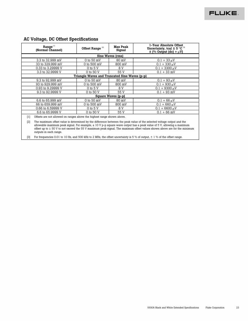
AC Voltage, DC Offset Specifications
Range [1] (Normal Channel) Offset Range [2] Max Peak
Signal
1-Year Absolute Offset Uncertainty, tcal ± 5 °C [3]
± (% Output (dc) + µV) Sine Waves (rms)
3.3 to 32.999 mV 0 to 50 mV 80 mV 0.1 + 33 µV 33 to 329.999 mV 0 to 500 mV 800 mV 0.1 + 330 µV 0.33 to 3.29999 V 0 to 5 V 8 V 0.1 + 3300 µV 3.3 to 32.9999 V 0 to 50 V 55 V 0.1 + 33 mV
Triangle Waves and Truncated Sine Waves (p-p) 9.3 to 92.999 mV 0 to 50 mV 80 mV 0.1 + 93 µV 93 to 929.999 mV 0 to 500 mV 800 mV 0.1 + 930 µV 0.93 to 9.29999 V 0 to 5 V 8 V 0.1 + 9300 µV 9.3 to 92.9999 V 0 to 50 V 55 V 0.1 + 93 mV
Square Waves (p-p) 6.6 to 65.999 mV 0 to 50 mV 80 mV 0.1 + 66 µV 66 to 659.999 mV 0 to 500 mV 800 mV 0.1 + 660 µV 0.66 to 6.59999 V 0 to 5 V 8 V 0.1 + 6600 µV 6.6 to 65.9999 V 0 to 50 V 55 V 0.1 + 66 mV
[1] Offsets are not allowed on ranges above the highest range shown above.
[2] The maximum offset value is determined by the difference between the peak value of the selected voltage output and the allowable maximum peak signal. For example, a 10 V p-p square wave output has a peak value of 5 V, allowing a maximum offset up to ± 50 V to not exceed the 55 V maximum peak signal. The maximum offset values shown above are for the minimum outputs in each range.
[3] For frequencies 0.01 to 10 Hz, and 500 kHz to 2 MHz, the offset uncertainty is 5 % of output, ± 1 % of the offset range.
24 Fluke Corporation 5500A Black and White Extended Specifications
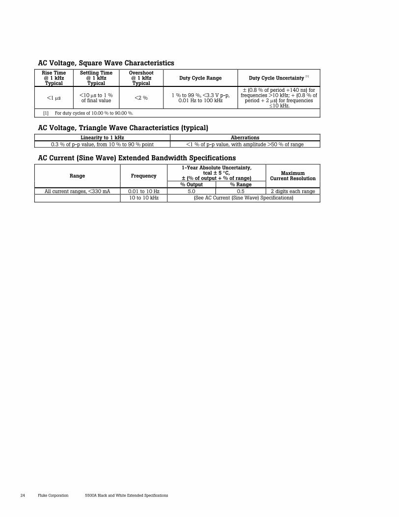
AC Voltage, Square Wave Characteristics Rise Time @ 1 kHz Typical
Settling Time @ 1 kHz Typical
Overshoot @ 1 kHz Typical
Duty Cycle Range Duty Cycle Uncertainty [1]
<1 µs <10 µs to 1 % of final value <2 % 1 % to 99 %, <3.3 V p-p,
0.01 Hz to 100 kHz
± (0.8 % of period +140 ns) for frequencies >10 kHz; + (0.8 % of
period + 2 µs) for frequencies ≤10 kHz.
[1] For duty cycles of 10.00 % to 90.00 %.
AC Voltage, Triangle Wave Characteristics (typical) Linearity to 1 kHz Aberrations
0.3 % of p-p value, from 10 % to 90 % point <1 % of p-p value, with amplitude >50 % of range
AC Current (Sine Wave) Extended Bandwidth Specifications 1-Year Absolute Uncertainty,
tcal ± 5 °C, ± (% of output + % of range) Range Frequency
% Output % Range
Maximum Current Resolution
All current ranges, <330 mA 0.01 to 10 Hz 5.0 0.5 2 digits each range 10 to 10 kHz (See AC Current (Sine Wave) Specifications)
5500A Black and White Extended Specifications Fluke Corporation 25
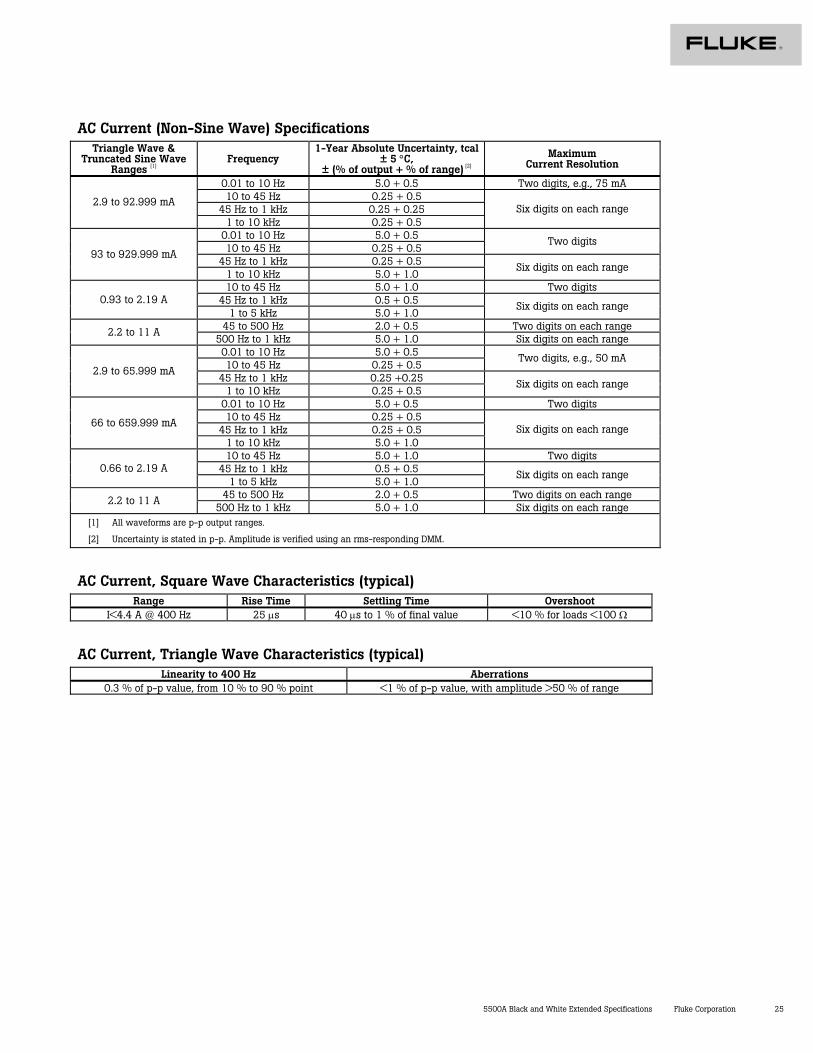
AC Current (Non-Sine Wave) Specifications Triangle Wave &
Truncated Sine Wave Ranges [1]
Frequency 1-Year Absolute Uncertainty, tcal
± 5 °C, ± (% of output + % of range) [2]
Maximum Current Resolution
0.01 to 10 Hz 5.0 + 0.5 Two digits, e.g., 75 mA 10 to 45 Hz 0.25 + 0.5
45 Hz to 1 kHz 0.25 + 0.25 2.9 to 92.999 mA
1 to 10 kHz 0.25 + 0.5 Six digits on each range
0.01 to 10 Hz 5.0 + 0.5 10 to 45 Hz 0.25 + 0.5
Two digits
45 Hz to 1 kHz 0.25 + 0.5 93 to 929.999 mA
1 to 10 kHz 5.0 + 1.0 Six digits on each range
10 to 45 Hz 5.0 + 1.0 Two digits 45 Hz to 1 kHz 0.5 + 0.5 0.93 to 2.19 A
1 to 5 kHz 5.0 + 1.0 Six digits on each range
45 to 500 Hz 2.0 + 0.5 Two digits on each range 2.2 to 11 A 500 Hz to 1 kHz 5.0 + 1.0 Six digits on each range 0.01 to 10 Hz 5.0 + 0.5 10 to 45 Hz 0.25 + 0.5
Two digits, e.g., 50 mA
45 Hz to 1 kHz 0.25 +0.25 2.9 to 65.999 mA
1 to 10 kHz 0.25 + 0.5 Six digits on each range
0.01 to 10 Hz 5.0 + 0.5 Two digits 10 to 45 Hz 0.25 + 0.5
45 Hz to 1 kHz 0.25 + 0.5 66 to 659.999 mA
1 to 10 kHz 5.0 + 1.0 Six digits on each range
10 to 45 Hz 5.0 + 1.0 Two digits 45 Hz to 1 kHz 0.5 + 0.5 0.66 to 2.19 A
1 to 5 kHz 5.0 + 1.0 Six digits on each range
45 to 500 Hz 2.0 + 0.5 Two digits on each range 2.2 to 11 A 500 Hz to 1 kHz 5.0 + 1.0 Six digits on each range
[1] All waveforms are p-p output ranges.
[2] Uncertainty is stated in p-p. Amplitude is verified using an rms-responding DMM.
AC Current, Square Wave Characteristics (typical) Range Rise Time Settling Time Overshoot
I<4.4 A @ 400 Hz 25 µs 40 µs to 1 % of final value <10 % for loads <100 Ω
AC Current, Triangle Wave Characteristics (typical) Linearity to 400 Hz Aberrations
0.3 % of p-p value, from 10 % to 90 % point <1 % of p-p value, with amplitude >50 % of range
Fluke Corporation PO Box 9090, Everett, WA USA 98206
Fluke Europe B.V.PO Box 1186, 5602 BD Eindhoven, The Netherlands
For more information call:In the U.S.A. (800) 443-5853 or Fax (425) 446-5116Europe/M-East/Africa +31 (40) 2 675 200 or Fax +31 (40) 2 675 222Canada (800) 36-FLUKE or Fax (905) 890-6866From other countries +1 (425) 446-5500 orFax +1 (425) 446-5116Web access: http://www.fluke.com
©2005 Fluke Corporation. All rights reserved. Printed in U.S.A. 9/2005 1264848 D-EN-N Rev D
Fluke. Keeping your world up and running.
CERTIFIED TO M EET IS
O 9
001
®
QUA
LI
TY MANAGEMENT SYSTEM
ISO 9001


![5522A Multi-Product Calibrator - MEGACAL · 4 Fluke Calibration 5522A Multi-Product Calibrator Extended Specifications Range Noise ... pm of ut [3] Fl or ( ) Time and temp since ohms](https://img.pdfslide.net/doc/110x75/5adcee687f8b9a9a768c31f0/5522a-multi-product-calibrator-fluke-calibration-5522a-multi-product-calibrator.jpg)