Embed Size (px)
Citation preview
8/13/2019 California High-Speed Train Project Design Criteria
http://slidepdf.com/reader/full/california-high-speed-train-project-design-criteria 1/116

8/13/2019 California High-Speed Train Project Design Criteria
http://slidepdf.com/reader/full/california-high-speed-train-project-design-criteria 2/116
8/13/2019 California High-Speed Train Project Design Criteria
http://slidepdf.com/reader/full/california-high-speed-train-project-design-criteria 3/116
California High-Speed Train Project Design Criteria
Chapter 12 – Structures
Page 12-iDecember 07, 2012, Rev. 0.1
Table of Contents
12 STRUCTURES ........................................................................................................... 12-1 1
12.1 Scope ..................................................................................................................... 12-1 212.2 Regulations, Codes, Standards, and Guidelines ..................................................... 12-1 312.3 Types of Structures ................................................................................................. 12-2 412.4 Structural Design Requirements ............................................................................. 12-3 5
12.4.1 Structural Design Parameters ...................................................................................... 12-3 612.4.2 Seismic Design ............................................................................................................ 12-4 7
12.5 Permanent and Transient Loads and Load Factors for Structures Supporting HST 12-4 812.5.1 Permanent Loads ........................................................................................................ 12-4 912.5.2 Transient Loads ........................................................................................................... 12-7 1012.5.3 Miscellaneous Loads ................................................................................................. 12-25 1112.5.4 Load Factors and Load Modifiers ............................................................................... 12-28 12
12.6
Track-Structure Interaction .................................................................................... 12-33
13 12.6.1 Design Requirements ................................................................................................ 12-34 1412.6.2 Design Parameters .................................................................................................... 12-34 1512.6.3 Frequency Analysis ................................................................................................... 12-35 1612.6.4 Track Serviceability Analysis...................................................................................... 12-38 1712.6.5 Rail-Structure Interaction Analysis ............................................................................. 12-48 1812.6.6 Dynamic Structural Analysis ...................................................................................... 12-55 1912.6.7 Dynamic Vehicle-Track-Structure Interaction Analysis................................................ 12-59 2012.6.8 Modeling Requirements ............................................................................................. 12-61 21
12.7 Structural Design of Surface Facilities and Buildings ............................................ 12-68 2212.7.1 Load Requirements for Stations, Surface Facilities and Buildings............................... 12-68 2312.7.2 Foundations for Equipment Enclosures ...................................................................... 12-74 2412.7.3 Foundations for Utility Equipment .............................................................................. 12-74 25
12.8 Design Considerations for Bridges and Aerial Structures ...................................... 12-74 2612.8.1 General Design Requirements ................................................................................... 12-75 2712.8.2 Design Loads and Effects .......................................................................................... 12-79 2812.8.3 Foundations............................................................................................................... 12-79 2912.8.4 Steel Structures ......................................................................................................... 12-80 3012.8.5 Concrete Structures ................................................................................................... 12-81 3112.8.6 General Aerial Structure and Bridge Design Features ................................................ 12-82 3212.8.7 Complex and Non-Standard Aerial Structures ............................................................ 12-88 3312.8.8 Emergency Access .................................................................................................... 12-89 3412.8.9 OCS Pole and Traction Power Facility Gantry Supports ............................................. 12-89 3512.8.10 Maintenance of HST Aerial Structures, Bridges, and Grade Separations ................ 12-89 36
12.9 Requirements for Bridges not Supporting HST ..................................................... 12-90 3712.9.1 Load Requirements for New Primary Type 2 Pedestrian Bridges ................................ 12-90 3812.9.2 Load Requirements for New Secondary Pedestrian Bridges....................................... 12-90 3912.9.3 Requirements for Highway Bridges ............................................................................ 12-91 4012.9.4 Requirements for New Railway Bridges ..................................................................... 12-92 4112.9.5 Requirements for Existing Railway Bridges ................................................................ 12-93 4212.9.6 Intrusion Protection.................................................................................................... 12-93 43
12.10 Earth Retaining Structures................................................................................. 12-93 4412.10.1 Earth Pressure Acting on Retaining Structures ....................................................... 12-93 45
8/13/2019 California High-Speed Train Project Design Criteria
http://slidepdf.com/reader/full/california-high-speed-train-project-design-criteria 4/116
California High-Speed Train Project Design Criteria
Chapter 12 – Structures
Page 12-iiDecember 07, 2012, Rev. 0.1
12.10.2 Retaining Walls...................................................................................................... 12-93 112.10.3 MSE Walls ............................................................................................................. 12-94 212.10.4 Trenches ............................................................................................................... 12-94 312.10.5 Trench Intrusion Protection .................................................................................... 12-94 412.10.6 Struts ..................................................................................................................... 12-94 5
12.10.7 Trench Drainage .................................................................................................... 12-94 612.10.8 Trench Emergency Exits ........................................................................................ 12-95 7
12.11 Cut-and-Cover Structures .................................................................................. 12-95 812.11.1 Structural System .................................................................................................. 12-95 912.11.2 Loads and Forces .................................................................................................. 12-95 1012.11.3 Waterproofing of Underground Station Structures ................................................ 12-101 1112.11.4 Water Holding and Conveyance Structures .......................................................... 12-104 1212.11.5 Shoring Systems.................................................................................................. 12-104 1312.11.6 Structural Fire Resistance .................................................................................... 12-104 14
12.12 Support and Underpinning of Structures .......................................................... 12-105 1512.12.1 Depth of Support Structures ................................................................................. 12-105 1612.12.2 Methods .............................................................................................................. 12-105 17
12.13 Areas of Potential Explosion ............................................................................ 12-106 1812.14 Structure Interface Issues ................................................................................ 12-107 19
12.14.1 Cable Trough ....................................................................................................... 12-107 2012.14.2 Grounding and Bonding ....................................................................................... 12-107 2112.14.3 Drainage .............................................................................................................. 12-107 2212.14.4 Conduit Risers ..................................................................................................... 12-107 2312.14.5 Embedded Conduits ............................................................................................ 12-107 2412.14.6 Trackside Equipment ........................................................................................... 12-107 2512.14.7 Access Stairs ....................................................................................................... 12-108 2612.14.8 Overhead Concrete Anchors ................................................................................ 12-108 2712.14.9 Utilities................................................................................................................. 12-108 28
29
Tables
Table 12-1: Unit Weight of Common Materials ................................................................ 12-5 Table 12-2: Loads for Design of Overhead Contact System Pole Foundation ............... 12-26 Table 12-3: Loads and Load Combinations for Design of Traction Power Facility Gantry Pole
Foundation ................................................................................................. 12-27 Table 12-4: Load Combinations for Design of Structures............................................... 12-30 Table 12-5: Loading Definitions Used in Table 12-4 ...................................................... 12-31 Table 12-6: Load Factors for Permanent Loads, P ........................................................ 12-32 Table 12-7: Load Factors for Permanent Loads due to Superimposed Deformations, P 12-32 Table 12-8: Analysis Goals............................................................................................ 12-34 Table 12-9: Vertical Deflection Limits: Group 1a ............................................................ 12-39 Table 12-10: Vertical Deflection Limits: Group 1b ............................................................ 12-40 Table 12-11: Transverse Deflection Limits ...................................................................... 12-41 Table 12-12: Rotation about Transverse Axis and Relative Displacement at the Level of the
Rail Limits ................................................................................................... 12-43
8/13/2019 California High-Speed Train Project Design Criteria
http://slidepdf.com/reader/full/california-high-speed-train-project-design-criteria 5/116
California High-Speed Train Project Design Criteria
Chapter 12 – Structures
Page 12-iiiDecember 07, 2012, Rev. 0.1
Table 12-13: Rotation about Vertical Axis and Relative Displacement at Outermost Rail Limits 12-45
Table 12-14: Relative Vertical Displacement at Expansion Joints Limits – Track Serviceability 12-46
Table 12-15: Relative Transverse Displacement at Expansion Joints Limits – Track
Serviceability .............................................................................................. 12-47 Table 12-16: Deck Twist Limits........................................................................................ 12-47 Table 12-17: Relative Longitudinal Displacement at Expansion Joints Limits ................. 12-52 Table 12-18: Relative Vertical Displacement at Expansion Joints Limits ......................... 12-53 Table 12-19: Relative Transverse Displacement at Expansion Joints Limits.................... 12-54 Table 12-20: Minimum Factor of Safety for Uplift on Direct Fixation Fasteners................ 12-55 Table 12-21: Permissible Additional Axial Rail Stress Limits ........................................... 12-55 Table 12-22: Dynamic Track Safety Limits ...................................................................... 12-61 Table 12-23: Damping Values for Dynamic Model ........................................................... 12-63 Table 12-24: Minimum Recommended Track Extension and Boundary Spring Properties .. 12-
67 Table 12-25: Joint Location Limitations at Low-Speed Turnouts ...................................... 12-85 Table 12-26: Joint Location Limitations at High-Speed Turnouts ..................................... 12-86
Figures
Figure 12-1: Cooper E-50 Loading (LLRR) ....................................................................... 12-8 Figure 12-2: Equivalent Loads q1k for Simple Vertical Surfaces Parallel to the Track for
Speeds Less than 125 mph ........................................................................ 12-15 Figure 12-3: Equivalent Loads q1k for Simple Vertical Surfaces Parallel to Track for Speeds
Greater than 125 mph ................................................................................ 12-16 Figure 12-4: Equivalent Loads q2k for Simple Horizontal Surfaces Above Track for Speeds
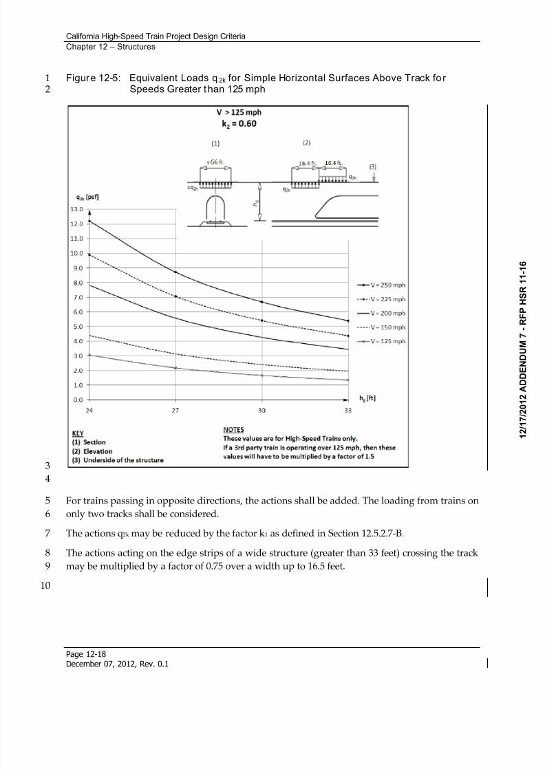
Less than 125 mph ..................................................................................... 12-17 Figure 12-5: Equivalent Loads q2k for Simple Horizontal Surfaces Above Track for Speeds
Greater than 125 mph ................................................................................ 12-18 Figure 12-6: Equivalent Loads q3k for Simple Horizontal Surfaces Adjacent to Track...... 12-19 Figure 12-7: Definition of the Distances min ag and max ag from Centerline of Track...... 12-20 Figure 12-8: Derailment Case I ....................................................................................... 12-23 Figure 12-9: Derailment Case II ...................................................................................... 12-23 Figure 12-10: LLRM Loading ............................................................................................ 12-34 Figure 12-11: Recommended Range of Vertical Frequency ............................................. 12-37 Figure 12-12: Transverse Span Deformation Limits.......................................................... 12-41 Figure 12-13: Rotation about Transverse Axis at Deck Ends ............................................ 12-42 Figure 12-14: Rotation about Vertical Axis at Deck Ends – Global View ........................... 12-44 Figure 12-15: Rotation about Vertical Axis at Deck Ends – Local View ............................. 12-44 Figure 12-16: Relative Vertical Displacement at Expansion Joints – Track Serviceability . 12-45 Figure 12-17: Relative Transverse Displacement at Expansion Joints – Track Serviceability 12-
46 Figure 12-18: Deck Twist Diagram ................................................................................... 12-47
8/13/2019 California High-Speed Train Project Design Criteria
http://slidepdf.com/reader/full/california-high-speed-train-project-design-criteria 6/116
California High-Speed Train Project Design Criteria
Chapter 12 – Structures
Page 12-ivDecember 07, 2012, Rev. 0.1
Figure 12-19: LF Definition ............................................................................................... 12-50 Figure 12-20: LLRM+I Definition ......................................................................................... 12-50 Figure 12-21: OBE Definition............................................................................................. 12-51 Figure 12-22: Relative Vertical Displacement at Expansion Joints.................................... 12-53 Figure 12-23: Relative Transverse Displacement at Expansion Joints .............................. 12-54 Figure 12-24: Type 1 ........................................................................................................ 12-56 Figure 12-25: Type 2 ........................................................................................................ 12-56 Figure 12-26: Type 3 ........................................................................................................ 12-57 Figure 12-27: Type 4 ........................................................................................................ 12-57 Figure 12-28: Type 5 ........................................................................................................ 12-57 Figure 12-29: Characteristic Wheel Spacing, d ................................................................. 12-58 Figure 12-30: Rail-Structure Interaction Model ................................................................. 12-64 Figure 12-31: Non-Ballasted Track with Direct Fixation Fasteners: Bi-linear Coupling Springs
12-65 Figure 12-32: Collision Loads for Each Group of Columns ............................................... 12-72 Figure 12-33: Protection Device ....................................................................................... 12-73 Figure 12-34: Joint Location Limitations at Low-Speed Turnouts ...................................... 12-85 Figure 12-35: Joint Location Limitations at High-Speed Turnouts ..................................... 12-86
8/13/2019 California High-Speed Train Project Design Criteria
http://slidepdf.com/reader/full/california-high-speed-train-project-design-criteria 7/116
California High-Speed Train Project Design Criteria
Chapter 12 – Structures
Page 12-vDecember 07, 2012, Rev. 0.1
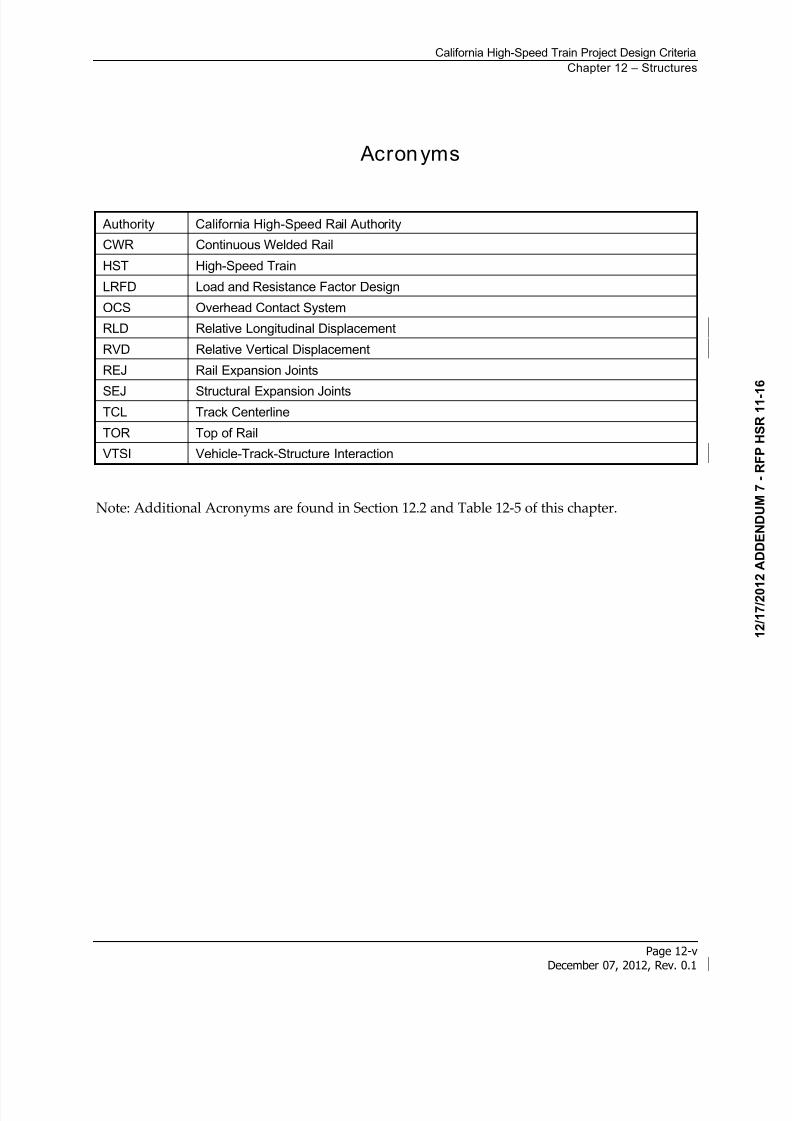
Acronyms
Authority California High-Speed Rail Authority
CWR Continuous Welded Rail
HST High-Speed Train
LRFD Load and Resistance Factor Design
OCS Overhead Contact System
RLD Relative Longitudinal Displacement
RVD Relative Vertical Displacement
REJ Rail Expansion Joints
SEJ Structural Expansion JointsTCL Track Centerline
TOR Top of Rail
VTSI Vehicle-Track-Structure Interaction
Note: Additional Acronyms are found in Section 12.2 and Table 12-5 of this chapter.

8/13/2019 California High-Speed Train Project Design Criteria
http://slidepdf.com/reader/full/california-high-speed-train-project-design-criteria 8/116
8/13/2019 California High-Speed Train Project Design Criteria
http://slidepdf.com/reader/full/california-high-speed-train-project-design-criteria 9/116
California High-Speed Train Project Design Criteria
Page 12-1December 07, 2012, Rev. 0.1
12 Structures
12.1 Scope
This chapter provides design criteria for structures supporting California High-Speed Train1
(HST) service including but not limited to bridges, aerial structures, grade separations, earth2
retaining structures, cut-and-cover underground structures, station structures, surface facilities3
and buildings.4
12.2 Regulations, Codes, Standards, and Guidelines
Refer to the General chapter for requirements pertaining to regulations, codes, and standards.5
Design shall meet applicable portions of the general laws and regulations of the State of6
California and of respective local authorities. Facilities shall be designed in accordance with7applicable portions of the following standards and codes:8
American Concrete Institute (ACI)9
- ACI 318: Building Code Requirements for Reinforced Concrete10
- ACI 350: Code Requirements for Environmental Engineering Concrete Structures and11
Commentary12
American Welding Society (AWS)13
- AWS D1.1/D1.1M Structural Welding Code-Steel14
- AWS D1.8/D1.8M Structural Welding Code-Seismic Supplement15
American Association of State Highway and Transportation Officials (AASHTO)/AWS16
D1.5M/D1.5 Bridge Welding Code17
California Building Code (CBC)18
American Railway Engineering and Maintenance-of-Way Association (AREMA) Manual for19
Railway Engineering20
American Institute of Steel Construction (AISC), Steel Construction Manual,21
American Society of Civil Engineers (ASCE) 7-05; Minimum Design Loads for Buildings and22
Other Structures23
California Occupational Safety and Health Administration (Cal/OSHA) Department of24
Industrial Relations25
California Department of Transportation (Caltrans) Bridge Design Manuals26
8/13/2019 California High-Speed Train Project Design Criteria
http://slidepdf.com/reader/full/california-high-speed-train-project-design-criteria 10/116
California High-Speed Train Project Design Criteria
Chapter 12 – Structures
Page 12-2December 07, 2012, Rev. 0.1
Bridge Design Specification (CBDS) - AASHTO LRFD Bridge Design Specification with1
California Amendments2
Bridge Memo to Designers Manual (CMTD)3
Bridge Design Practices Manual (CBPD)4
Bridge Design Aids Manual (CBDA)5
Bridge Design Details Manual (CBDD)6
Seismic Design Criteria (CSDC)7
Office of Special Funded Projects (OSFP) Information and Procedures Guide8
Code of Federal Regulations (CFR)9
United States Department of Transportation Federal Highway Administration; Technical10
Manual for Design and Construction of Road Tunnels – Civil Elements; Publication No.11
FHWA-NHI-09-01012
Other international standards are used in the development of these criteria, including the13
following:14
European Standard EN 1991-2:2003 Actions on Structures – Part 2: Traffic Loads on Bridges15
European Standard EN 1990:2002 +A1 Basis of Structural Design annex A2: Application to16
Bridges17
International Federation for Structural Concrete (FIB) Model Code for Concrete Structures,18
1990 (For Time Dependent Behavior of Concrete)19
12.3 Types of Structures
Structures supporting high-speed train service are classified as the following:20
Bridges – HST trackway structures crossing rivers, lakes, or other bodies of water21
Aerial Structures – elevated HST trackway structures including bridges, viaducts and HST22
grade separations23
Grade Separations – structures separating trackways from railroad, highway or pedestrian24
usage25
Earth Retaining Structures – including U-walls, trenches, and retaining walls26
Cut-and-Cover Underground structures – including cut-and-cover line structures27
Bored Tunnels28
Mined Tunnels29
8/13/2019 California High-Speed Train Project Design Criteria
http://slidepdf.com/reader/full/california-high-speed-train-project-design-criteria 11/116
California High-Speed Train Project Design Criteria
Chapter 12 – Structures
Page 12-3December 07, 2012, Rev. 0.1
Surface Facilities and Buildings – including station buildings, station parking structures,1
secondary and ancillary buildings, sound walls, and miscellaneous structures2
Underground Ventilation Structures3
Underground Passenger Stations4
Equipment and Equipment Supports5
12.4 Structural Design Requi rements
Structures shall be designed for specified limit states to achieve the objectives of6
constructability, safety, and serviceability, with the consideration of inspectability, and7
maintainability, as specified in AASHTO LRFD with California Amendments unless otherwise8
modified here.9
12.4.1 Structural Design Parameters
Structures shall be designed for the appropriate loadings and shall comply with the HST10
structure gauge per the Trackway Clearances chapter.11
The design life for structures shall be 100 years. Elements such as expansion joints and12
bearings that need to be replaced in the life of the structures, the Contractor shall evaluate13
the life of each element and specify the replacement procedures which the element can be14
replaced within the non-operation hours of the HST service.15
Requirements for noise and vibration are defined in the environmental documents16
including materials and specific locations and measurements.17
Structural design criteria shall apply to structures adjacent to, above, or below the HST18
tracks and which performance could directly affect HST operation. This includes aerial19
structures carrying HSTs and newly constructed highway or ancillary structures which will20
directly affect the HST operations.21
Structures shall be designed so that the elements normally replaced during maintenance can22
be readily replaced with minimal impact to HST operations.23
The bridges and aerial superstructures supporting HSTs shall be designed to meet stiffness24
requirements in order to meet serviceability and comfort requirements for HST operation.25
Permanent and temporary structures including falsework shall be designed in accordance26
with the clearance requirements. Clearance requirements for falsework are only applicable27
where the falsework is erected over an operational road or railway.28
Design of structures shall consider loads and effects due to erection equipment, construction29
methods, and sequence of construction.30
Design and construction of HST facilities shall comply with the approved and permitted31
environmental documents.32
8/13/2019 California High-Speed Train Project Design Criteria
http://slidepdf.com/reader/full/california-high-speed-train-project-design-criteria 12/116
California High-Speed Train Project Design Criteria
Chapter 12 – Structures
Page 12-4December 07, 2012, Rev. 0.1
Only non-flammable materials are allowed in construction. Timber is allowed in1
construction of falsework.2
12.4.2 Seismic Design
For definition of structural classification as Primary or Secondary structures, refer to the Seismic 3
chapter. For seismic design criteria for Primary and Secondary structures, as defined in the4
Seismic chapter, refer to the Seismic chapter.5
12.5 Permanent and Transient Loads and Load Factors for StructuresSupporting HST
This section specifies the loads and forces, load factors and load combinations for the6
application of permanent and transient loads for structures directly supporting HST. This7
section defines loads specific to bridges, aerial structures, and grade separations. These loads8
are applicable to earth retaining structures and cut-and-cover structures.9
Facility loads, such as those for buildings and stations not supporting high-speed trains, are10
specified in Section 12.7 - Structural Design of Surface Facilities and Buildings.11
For structures carrying highway loads, AASHTO LRFD with Caltrans Amendments shall apply12
with supplementary provisions herein to account for loads or seismic performance criteria13
specific to HST operations.14
The dynamic analyses to determine dynamic impact factors and ensure the passenger comfort15
associated with HST rolling stock loadings and the requirements of the track-structure16
interaction are defined in Section 12.6 - Track-Structure Interaction.17
12.5.1 Permanent Loads
12.5.1.1 Dead Load (DC, DW)
The dead load shall include the weight of structure components, appurtenances, utilities18
attached to the structure, earth cover, finishes, and permanent installations such as tracks,19
ballast, conduits, piping, safety walkways, walls, sound walls, electrification and utility20
services.21
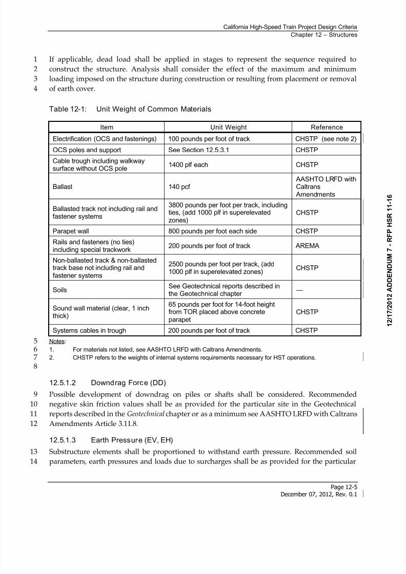
In the absence of more precise information, the unit weights specified in Table 12-1 shall be22
used for dead loads.23
DC refers to the dead load of structural components and permanent attachments supported by24
the structure including, tracks, ballast, plinths, cable troughs, parapet walls, sound walls,25
overhead contact system (OCS), etc.26
DW refers to the dead load of non-structural attachments which are permanent or non-27
permanent attachments including, utilities, cables, finishes, etc.28
8/13/2019 California High-Speed Train Project Design Criteria
http://slidepdf.com/reader/full/california-high-speed-train-project-design-criteria 13/116
California High-Speed Train Project Design Criteria
Chapter 12 – Structures
Page 12-5December 07, 2012, Rev. 0.1
If applicable, dead load shall be applied in stages to represent the sequence required to1
construct the structure. Analysis shall consider the effect of the maximum and minimum2
loading imposed on the structure during construction or resulting from placement or removal3
of earth cover.4
Table 12-1: Unit Weight of Common Materials
Item Unit Weight Reference
Electrification (OCS and fastenings) 100 pounds per foot of track CHSTP (see note 2)
OCS poles and support See Section 12.5.3.1 CHSTP
Cable trough including walkwaysurface without OCS pole
1400 plf each CHSTP
Ballast 140 pcf AASHTO LRFD withCaltrans
Amendments
Ballasted track not including rail andfastener systems
3800 pounds per foot per track, includingties, (add 1000 plf in superelevatedzones)
CHSTP
Parapet wall 800 pounds per foot each side CHSTP
Rails and fasteners (no ties)including special trackwork
200 pounds per foot of track AREMA
Non-ballasted track & non-ballastedtrack base not including rail andfastener systems
2500 pounds per foot per track, (add1000 plf in superelevated zones)
CHSTP
SoilsSee Geotechnical reports described inthe Geotechnical chapter
—
Sound wall material (clear, 1 inchthick)
65 pounds per foot for 14-foot heightfrom TOR placed above concreteparapet
CHSTP
Systems cables in trough 200 pounds per foot of track CHSTP
Notes:51. For materials not listed, see AASHTO LRFD with Caltrans Amendments.62. CHSTP refers to the weights of internal systems requirements necessary for HST operations.7
8
12.5.1.2 Downdrag Force (DD)
Possible development of downdrag on piles or shafts shall be considered. Recommended9
negative skin friction values shall be as provided for the particular site in the Geotechnical10reports described in the Geotechnical chapter or as a minimum see AASHTO LRFD with Caltrans11
Amendments Article 3.11.8.12
12.5.1.3 Earth Pressure (EV, EH)
Substructure elements shall be proportioned to withstand earth pressure. Recommended soil13
parameters, earth pressures and loads due to surcharges shall be as provided for the particular14
8/13/2019 California High-Speed Train Project Design Criteria
http://slidepdf.com/reader/full/california-high-speed-train-project-design-criteria 14/116
California High-Speed Train Project Design Criteria
Chapter 12 – Structures
Page 12-6December 07, 2012, Rev. 0.1
site in the Geotechnical reports described in the Geotechnical chapter. See the Geotechnical chapter1
for determination of pressures acting on earth retaining structures. If site specific design data is2
not available, use AASHTO LRFD with Caltrans Amendments Article 3.11.3
A. Vertical Earth Pressure (EV)
Depth of cover shall be measured from the ground surface or roadway crown, or from the street4
grade, whichever is higher, to the top of the underground structure. Saturated densities of soils5
shall be used to determine the vertical earth pressure. Recommended values given in the6
Geotechnical chapter shall be used.7
B. Lateral Static Earth Pressure (EH)
For structures retaining draining cohesionless (granular) soil, lateral earth pressure shall be8
determined in accordance with the Geotechnical chapter. For structures retaining other soil types,9
the lateral soil pressure shall be in accordance with the recommendations specified in the10
Geotechnical chapter.11
C. Lateral Seismic Earth Pressure
For increases in earth pressures caused by seismic actions see the Geotechnical chapter.12
12.5.1.4 Earth Surcharge (ES)
Surcharge loads (ES) are vertical or lateral loads resulting from loads applied at or below the13
adjacent ground surface. Procedures for determining surcharge load shall be as given in the14
Geotechnical reports described in the Geotechnical chapter.15
12.5.1.5 Earth Settlement Effects (SE)
Earth settlement effects (SE) are forces or displacements imposed on a structure due to either16
uniform or differential settlement under sustained loading. Recommended values of settlement17as given in the Geotechnical Reports described in the Geotechnical chapter shall be used.18
Tolerable settlement on foundations shall be developed by the designer consistent with the19
function and type of structure, fixity of bearings, anticipated service life, and consequences of20
unacceptable displacements on structural and operational performance. Operational settlement21
limits are listed in the Geotechnical chapter.22
At and near water crossings, scour potential shall also be considered for earth settlement effects.23
12.5.1.6 Creep Effects (CR)
For the effects due to creep of concrete (CR), the requirements in AASHTO LRFD with Caltrans24Amendments Article 5 shall be used.25
12.5.1.7 Shrinkage Effects (SH)
For the effects due to shrinkage of concrete (SH), the requirements in AASHTO LRFD with26
Caltrans Amendments Article 5 shall be used.27
8/13/2019 California High-Speed Train Project Design Criteria
http://slidepdf.com/reader/full/california-high-speed-train-project-design-criteria 15/116
California High-Speed Train Project Design Criteria
Chapter 12 – Structures
Page 12-7December 07, 2012, Rev. 0.1
12.5.1.8 Secondary Forces from Prestressing (PS)
Secondary forces from prestressing (PS) shall be accounted for in the design. Such secondary1
forces arise during prestress of statically indeterminate structures, which produce additional2
internal forces and support reactions.3
12.5.1.9 Locked-in Construction Forces (EL)
Miscellaneous locked-in construction force effects (EL) resulting from the construction process4
shall be considered. Such effects include jacking apart adjacent cantilevers during segmental5
construction.6
12.5.1.10 Water Loads (WA)
The effects of ground water hydrostatic force, including static pressure of water, buoyancy,7
stream pressure, and wave loads (WA) shall be considered using the requirements in AASHTO8
LRFD with Caltrans Amendments Article 3.7. Recommended values given in the Geotechnical9
Reports described in the Geotechnical chapter shall be used. Refer to Section 12.11.2.7 for10
Hydrostatic pressure for trench and cut-and-cover structures.11
Adequate resistance to flotation shall be provided at sections for full uplift pressure on the12
structure foundation, based upon the maximum of either the maximum probable height of the13
water table defined in the Geotechnical Reports described in the Geotechnical chapter or the14
maximum flood condition based on the drainage requirements in the Drainage chapter. For the15
completed structure, uplift resistance shall consist of the dead weight of the completed structure16
and the weight of backfill overlying the structure (within vertical planes drawn through the17
outer edges of the structure roof and through the joints).18
Hydrostatic pressure shall be applied normal to surfaces in contact with groundwater with a19
magnitude based on the height of water table and the applicable water density.20
The change in foundation condition due to scour shall be investigated per AASHTO LRFD with21
Caltrans Amendments Article 3.7.5.22
12.5.2 Transient Loads
12.5.2.1 Live Loads (LLP, LLV, LLRR, LLH, LLS)
Live loads are due to high-speed trains, other trains (not HST), Amtrak, passenger rail, shared-23
use rail trains, highway loads, construction equipment, and pedestrians.24
A. Floor, Roof, and Pedestrian Live Loads (LLP)
For the force effects due to floor and roof live loads (LLP), refer to Section 12.7 - Structural25
Design of Surface Facilities and Buildings. Section 12.7 includes provisions for aerial trackway26
supporting service walkways.27
8/13/2019 California High-Speed Train Project Design Criteria
http://slidepdf.com/reader/full/california-high-speed-train-project-design-criteria 16/116
California High-Speed Train Project Design Criteria
Chapter 12 – Structures
Page 12-8December 07, 2012, Rev. 0.1
B. High-Speed Train Live Loads (LLV)
The project specific rolling stock has not yet been determined. Once the rolling stock is1
determined, the live load criteria will be included. Trainsets similar to those being considered2
are presented in Section 12.6.3
C. Shared-Use Track Train Live Loads (LLRR)
Structures that will support shared service with another railroad system such as AMTRAK,4
Caltrain, Metrolink, UPRR, BNSF, etc., have specific criteria that must be followed in addition to5
the requirements provided herein for high-speed trains.6
AMTRAK loading is describes in Section 12.5.2.1-E below. Additionally, design shall meet the7
requirements described in the Seismic chapter and Section 12.6 - Track-Structure Interaction.8
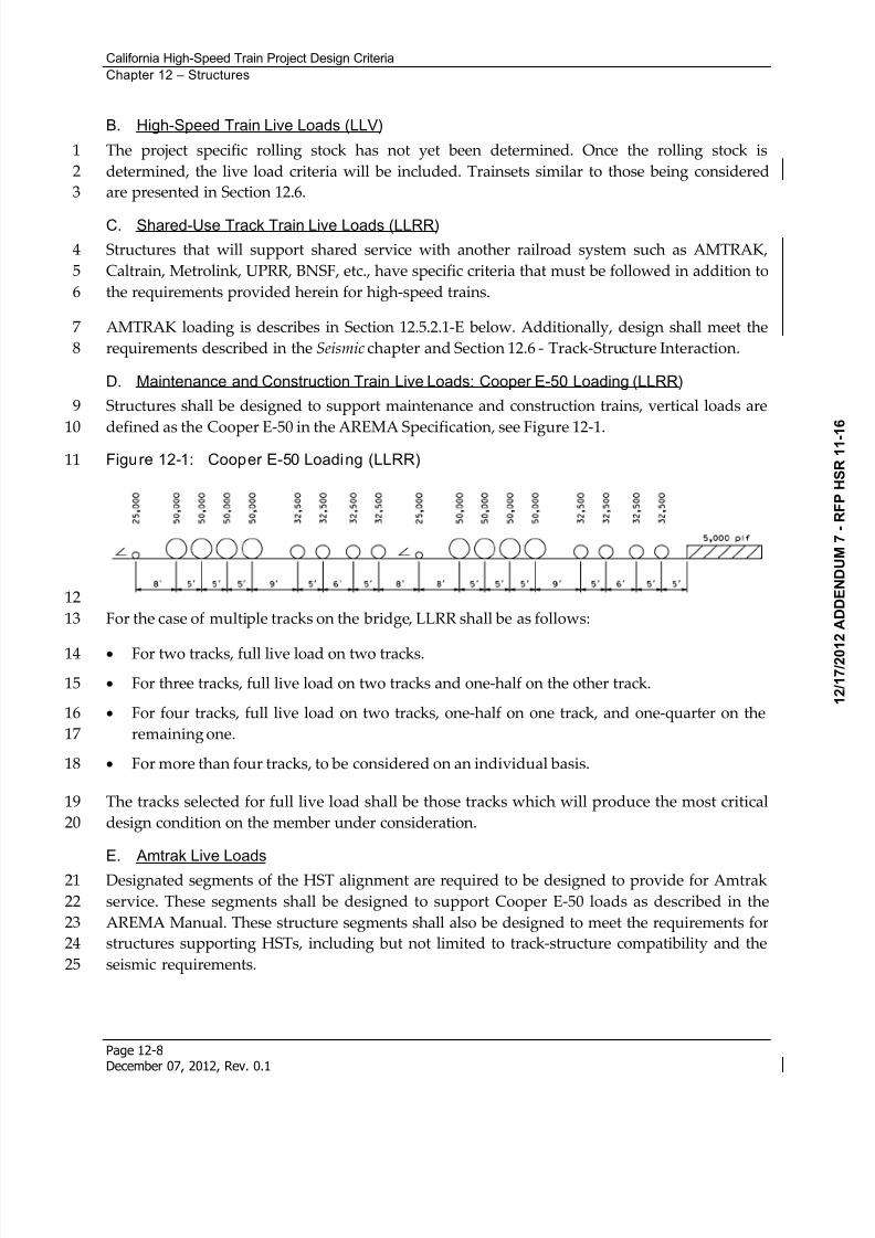
D. Maintenance and Construction Train Live Loads: Cooper E-50 Loading (LLRR)
Structures shall be designed to support maintenance and construction trains, vertical loads are9
defined as the Cooper E-50 in the AREMA Specification, see Figure 12-1.10Figure 12-1: Cooper E-50 Loading (LLRR)11
12
For the case of multiple tracks on the bridge, LLRR shall be as follows:13
For two tracks, full live load on two tracks.14
For three tracks, full live load on two tracks and one-half on the other track.15
For four tracks, full live load on two tracks, one-half on one track, and one-quarter on the16
remaining one.17
For more than four tracks, to be considered on an individual basis.18
The tracks selected for full live load shall be those tracks which will produce the most critical19
design condition on the member under consideration.20
E. Amtrak Live Loads
Designated segments of the HST alignment are required to be designed to provide for Amtrak21
service. These segments shall be designed to support Cooper E-50 loads as described in the22
AREMA Manual. These structure segments shall also be designed to meet the requirements for23
structures supporting HSTs, including but not limited to track-structure compatibility and the24
seismic requirements.25
8/13/2019 California High-Speed Train Project Design Criteria
http://slidepdf.com/reader/full/california-high-speed-train-project-design-criteria 17/116
California High-Speed Train Project Design Criteria
Chapter 12 – Structures
Page 12-9December 07, 2012, Rev. 0.1
These structures shall be designed to resist two axles weighting 75 kips each with a longitudinal1
spacing of 9.0 feet. This additional loading is required to account for local effects of Amtrak2
locomotives.3
F. Highway Live Loads (LLH)
Facilities required to support highway loads over HST shall be designed to the requirements of4
AASHTO LRFD with Caltrans Amendments Article 3.6.1. For facilities intended to support5
highway permit loads, Caltrans guidelines shall be followed for the routing and sizes of the6
permit vehicles.7
G. Live Load Surcharge (LLS)
An area live load surcharge (LLS) shall be applied at the ground surface both over and adjacent8
to underground structures, as applicable, to account for presence of live load. Live load9
surcharge results from presence of LLRR, LLV, LLH, possible future roadways, sidewalk live10
loads, or construction live loads.11
Methods for lateral distribution of live load surcharge due to rail loading shall be in accordance12
with AREMA. Lateral distribution of highway surcharge shall be in accordance with AASHTO13
LRFD with Caltrans Amendments Article 3.11.6.4.14
No impact factors apply to LLS for walls. A reduction of impact for buried components shall be15
applicable as specified in AASHTO LRFD with Caltrans Amendments Article 3.6.2, with the 3316
percent base impact value modified as applicable to LLRR or LLV, as given herein.17
Recommended coefficients for lateral surcharge loading shall be as recommended in the18
Geotechnical reports described in the Geotechnical chapter.19
H. Live Loading for Fatigue Assessment
For structures carrying high-speed trains, the project specific rolling stock (LLV) plus impact (I)20
shall be used for fatigue assessment of structures. Various trainsets LLV, that may be selected21
are described in Section 12.6.6.1 and dynamic impact shall be determined according to the22
requirements in Section 12.6.6.3. The methods of AASHTO LRFD with Caltrans Amendments23
Article 3.6.1.4 shall be used to evaluate fatigue loads.24
The fatigue assessment shall be performed for structural elements which are subjected to25
fluctuations of stress. For structures supporting multiple tracks the loading shall be applied to a26
minimum of 2 tracks in the most unfavorable positions. The fatigue damage shall be assessed27
over the required structural life of the structure. During maximum service condition there are282.8 million axle loads per track per year.29
12.5.2.2 Vertical Impact Effect (I)
Moving trains and vehicles impart dynamic loads to bridges, which are considered through a30
dynamic coefficient or impact factor. The static effects of the design train loads, other than31
centrifugal, traction, braking, nosing and hunting shall be increased by the percentages32
specified.33
8/13/2019 California High-Speed Train Project Design Criteria
http://slidepdf.com/reader/full/california-high-speed-train-project-design-criteria 18/116
California High-Speed Train Project Design Criteria
Chapter 12 – Structures
Page 12-10December 07, 2012, Rev. 0.1
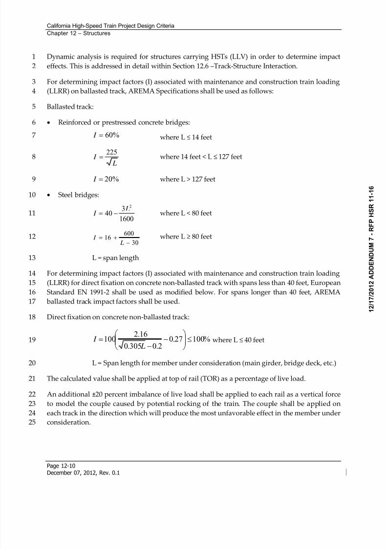
Dynamic analysis is required for structures carrying HSTs (LLV) in order to determine impact1
effects. This is addressed in detail within Section 12.6 –Track-Structure Interaction.2
For determining impact factors (I) associated with maintenance and construction train loading3
(LLRR) on ballasted track, AREMA Specifications shall be used as follows:4
Ballasted track:5
Reinforced or prestressed concrete bridges:6
%60 I where L 14 feet7
L I
225 where 14 feet < L 127 feet8
%20 I where L > 127 feet9
Steel bridges:10
1600
340
2 L I where L < 80 feet11
30
60016
L
I where L 80 feet12
L = span length13
For determining impact factors (I) associated with maintenance and construction train loading14
(LLRR) for direct fixation on concrete non-ballasted track with spans less than 40 feet, European15
Standard EN 1991-2 shall be used as modified below. For spans longer than 40 feet, AREMA16
ballasted track impact factors shall be used.17
Direct fixation on concrete non-ballasted track:18
%10027.02.0305.0
16.2100
L I where L 40 feet19
L = Span length for member under consideration (main girder, bridge deck, etc.)20
The calculated value shall be applied at top of rail (TOR) as a percentage of live load.21
An additional ±20 percent imbalance of live load shall be applied to each rail as a vertical force22
to model the couple caused by potential rocking of the train. The couple shall be applied on23
each track in the direction which will produce the most unfavorable effect in the member under24
consideration.25
8/13/2019 California High-Speed Train Project Design Criteria
http://slidepdf.com/reader/full/california-high-speed-train-project-design-criteria 19/116
California High-Speed Train Project Design Criteria
Chapter 12 – Structures
Page 12-11December 07, 2012, Rev. 0.1
For determining impact factors (I) associated with highway loading (LLH), AASHTO LRFD1
with Caltrans Amendments dynamic load allowance, IM as defined in AASHTO LRFD with2
Caltrans Amendments shall be used.3
Impact effect applies to the following:4
Superstructure, including steel or concrete supporting columns, steel towers, legs of rigid5
frames, and generally those portions of the structure which extend down to the main6
foundation.7
The portion above the ground line of concrete or steel piles that support the superstructure8
directly.9
Impact effect does not apply to the following:10
Retaining walls, wall-type piers, and piles except those described above.11
Foundations and footings entirely below ground, and base slabs which are in direct contact12with earth.13
Floor, roof, and pedestrian live loads (LLP).14
12.5.2.3 Centrifugal Force (CF)
For tracks on a curve, centrifugal force (CF) shall be considered as a horizontal load applied15
toward the outside of the curve. Multiple presence factors shall apply to centrifugal forces. See16
the Track Geometry chapter for the range of radius values.17
For centrifugal forces from carrying vehicular traffic, refer to AASHTO LRFD with Caltrans18
Amendments.19
The centrifugal force (CF) is a function of the train live load (LLRR or LLV), speed, and20
horizontal radius of curvature:21
For LLRR, use AREMA requirements22
For LLV, CF acts at 6 feet above TOR23
CF = (LLRR or LLV) x [0.0668*V2 *f / R]24
Where:25
V = train speed (mph)26
R = horizontal radius of curvature (feet)27
f = reduction factor, not to be taken less than 0.35:28
f = 1, for LLRR, for V 75 mph29
8/13/2019 California High-Speed Train Project Design Criteria
http://slidepdf.com/reader/full/california-high-speed-train-project-design-criteria 20/116
California High-Speed Train Project Design Criteria
Chapter 12 – Structures
Page 12-12December 07, 2012, Rev. 0.1
f = 1 - [(V - 75)/621.4] x [506/V + 1.75] x [1 - (9.45/ L)1/2] 0.35, for LLRR, V > 75 mph1
f = 1, for LLV, all speeds2
L = length in feet of the loaded portion of curved track on the bridge.3
If the maximum line speed at the site is in excess of 75 mph, the centrifugal force shall be4
investigated at 75 mph with a reduction factor of 1.0, and at the maximum line speed with a5
reduction factor less than 1.0.6
The effect of superelevation shall be considered when present. The superelevation effect shifts7
the centroid of the train laterally producing an unequal transverse distribution between rails.8
Consideration shall be given to the cases in which the train is moving and at rest condition.9
12.5.2.4 Traction and Braking Forces (LF)
A. LLRR
For traction and braking forces (LF) from passenger trains, freight trains, maintenance and10
construction trains (LLRR) taken from AREMA Section 2.2.3:11
Traction force = N(25 L) kips, acting 3 feet above TOR12
Braking force = N(45 + 1.2L) kips, acting 8 feet above TOR13
Where:14
L = length in feet of portion of bridge under consideration15
N = ratio of Cooper train load to Cooper E80 loading for the sizes of trains that will use16
the structure (i.e. for Cooper E50, N = 0.625)17
The LF loads for LLRR are to be distributed over the length of portion of bridge under18
consideration up to the maximum length of train. Multiple presence factors shall apply.19
B. LLV
For traction and braking forces (LF) from high-speed trains (LLV) taken from European20
Standard Eurocode EN 1991-2, Article 6.5.3:21
Traction force = 2.26 kips per linear foot or 25 percent of train load (if known), with a22
maximum value of 225 kips, acting at TOR23
Braking force = 1.37 kips per linear foot or 25 percent of train load (if known), with a24
maximum value of 1350 kips, acting at TOR25
Traction and braking forces will be reviewed and confirmed when the rolling stock is selected.26
8/13/2019 California High-Speed Train Project Design Criteria
http://slidepdf.com/reader/full/california-high-speed-train-project-design-criteria 21/116
California High-Speed Train Project Design Criteria
Chapter 12 – Structures
Page 12-13December 07, 2012, Rev. 0.1
C. LLH
For braking forces (LF) from highway loading (LLH), AASHTO LRFD with Caltrans1
Amendments Article 3.6.4 shall be used.2
12.5.2.5 Nosing and Hunting Effects (NE)
For structures with non-ballasted track and direct fixation fasteners, nosing and hunting effects3
(NE) of the wheels contacting the rails shall be accounted by a 22 kip horizontal force applied to4
the top of the low rail, perpendicular to the Track Centerline (TCL) at the most unfavorable5
position.6
NE is not applicable for the design of bridge decks with ballasted track. NE is not applicable to7
LLRR and LLH.8
NE shall be applied simultaneously with centrifugal force (CF).9
12.5.2.6 Wind Loads (WS, WL)
Wind Load on Structures (WS) and Wind Load on Trains (WL) shall be calculated in accordance10
with requirements in AASHTO LRFD with Caltrans Amendments Article 3.8 with the following11
modifications:12
The effective wind area shall include the exposed area of all bridge elements, OCS poles,13
and catenary. For parapets and barriers, shielding of downwind elements from those14
upwind shall not be considered (i.e., the exposed area shall include the summation of15
parapets on the bridge).16
The base lateral load for Wind Load on Vehicles (WL) shall be revised to 0.300 klf17
perpendicular to the train acting 8 feet above the TOR. AASHTO LRFD with Caltrans18
Amendments Table 3.8.1.3-1 Wind Components on Live Load for skewed angles of19
incidence shall be revised proportionally to reflect the modified base lateral load.20
For structures that utilize sound walls or wind walls capable of effectively shielding the21
train from wind loading, consideration may be given to a reduction of WL. The reduction22
may be taken as the fractional height of train that is shielded by the wall. This reduction23
shall not exceed 50 percent of WL.24
Local design elements such as parapets or components on structures shall be designed to wind25
loading and slipstream effects. Wind loading shall be calculated per CBC. The wind importance26
factor shall equal 1.15.27
Wind loading for non-conventional bridge types or long-spans will require special attention28
(e.g., dynamic effects).29
Wind loads (WS) on building and station structures are detailed in Section 12.7 – Structural30
Design of Surface Facilities and Buildings.31
8/13/2019 California High-Speed Train Project Design Criteria
http://slidepdf.com/reader/full/california-high-speed-train-project-design-criteria 22/116
California High-Speed Train Project Design Criteria
Chapter 12 – Structures
Page 12-14December 07, 2012, Rev. 0.1
Wind loads (WS, WL) on highway structures shall be per AASHTO LRFD with Caltrans1
Amendments.2
12.5.2.7 Slipstream Effects (SS)
A. Aerodynamic Actions from Passing TrainsThe passing of high-speed trains subjects structures situated near the track to transient pressure3
waves. This action may be approximated by equivalent loads acting at the front and rear of the4
train.5
Aerodynamic actions from passing trains shall be taken into account when designing structures6
adjacent to railway tracks.7
The passing of rail traffic subjects any structure situated near the track to a traveling wave of8
alternating pressure and suction (see Figures 12-2 to 12-7). The magnitude of the action depends9
mainly on:10
Square of the speed of the train11
Aerodynamic shape of the train12
Shape of the structure13
Position of the structure, particularly the clearance between the vehicle and the structure14
The actions may be approximated by equivalent loads at the ends of a train when checking15
ultimate and serviceability limit states and fatigue. Equivalent loads are given in Sections16
12.5.2.7-B to 12.5.2.7-G.17
In Sections 12.5.2.7-B to 12.5.2.7-G, the Maximum Design Speed V [mph] shall be taken as the18Maximum Line Speed at the site.19
At the start and end of structures adjacent to the tracks, for a length of 16.4 feet from the start20
and end of the structure measured parallel to the tracks, the equivalent loads in Sections21
12.5.2.7-B to 12.5.2.7-G shall be multiplied by a dynamic amplification factor of 2.0.22
Simple is defined here as smooth, without projections, ribs, or other obstruction.23
For aerodynamic actions inside of tunnels, see the Tunnels chapter.24
Note: For dynamically sensitive structures, the dynamic amplification factor may be insufficient25
and may need to be determined by a special study. The study shall take into account dynamic26
characteristics of the structure including support and end conditions, speed of the adjacent rail27
traffic and associated aerodynamic actions, and the dynamic response of the structure including28
the speed of a deflection wave induced in the structure. In addition, for dynamically sensitive29
structures a dynamic amplification factor may be necessary for parts of the structure between30
the start and end of the structure.31
8/13/2019 California High-Speed Train Project Design Criteria
http://slidepdf.com/reader/full/california-high-speed-train-project-design-criteria 23/116
California High-Speed Train Project Design Criteria
Chapter 12 – Structures
Page 12-15December 07, 2012, Rev. 0.1
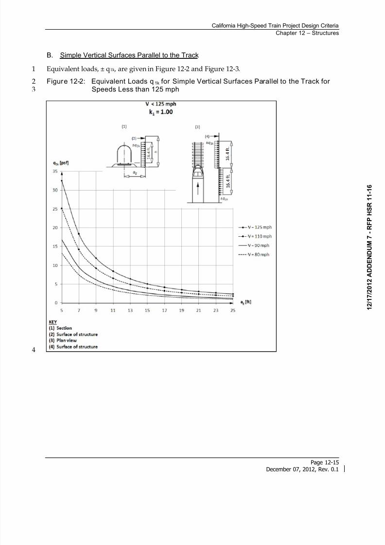
B. Simple Vertical Surfaces Parallel to the Track
Equivalent loads, ± q1k , are given in Figure 12-2 and Figure 12-3.1
Figure 12-2: Equivalent Loads q1k for Simple Vertical Surfaces Parallel to the Track for2Speeds Less than 125 mph3
4
8/13/2019 California High-Speed Train Project Design Criteria
http://slidepdf.com/reader/full/california-high-speed-train-project-design-criteria 24/116
California High-Speed Train Project Design Criteria
Chapter 12 – Structures
Page 12-16December 07, 2012, Rev. 0.1
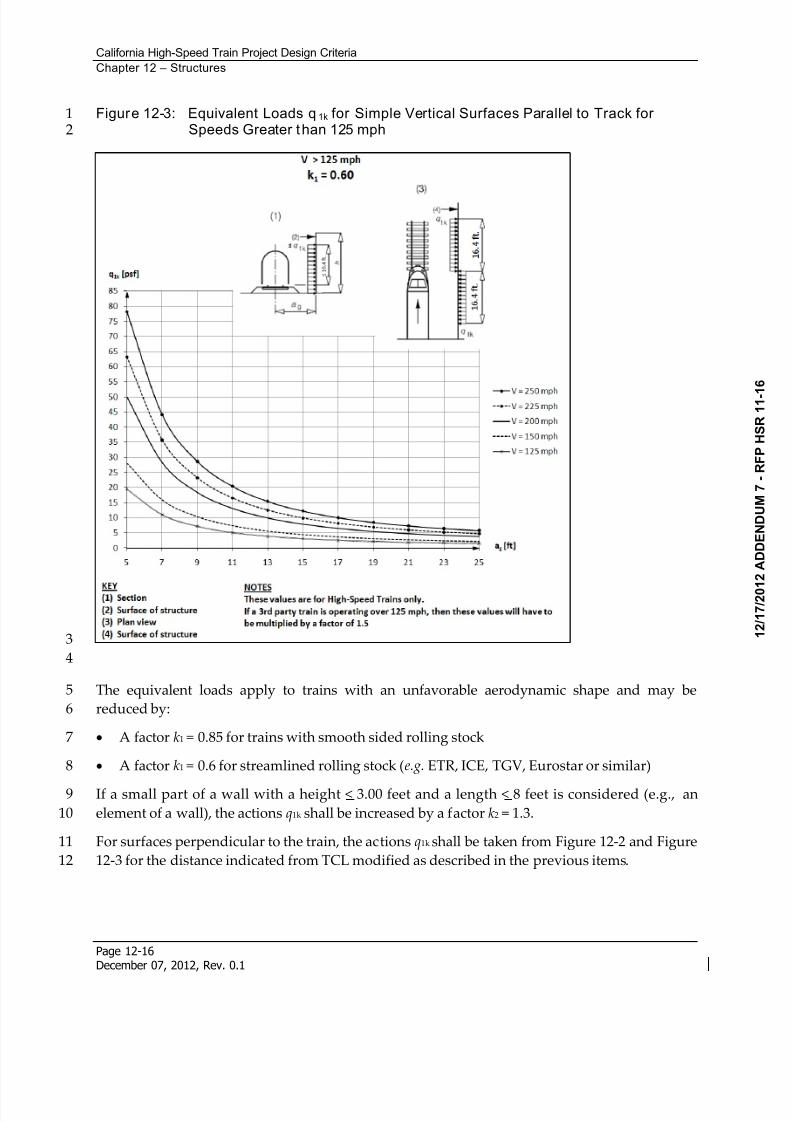
Figure 12-3: Equivalent Loads q1k for Simple Vertical Surfaces Parallel to Track for1Speeds Greater than 125 mph2
3
4
The equivalent loads apply to trains with an unfavorable aerodynamic shape and may be5
reduced by:6
A factor k1 = 0.85 for trains with smooth sided rolling stock7
A factor k1 = 0.6 for streamlined rolling stock (e.g. ETR, ICE, TGV, Eurostar or similar)8
If a small part of a wall with a height < 3.00 feet and a length < 8 feet is considered (e.g., an9
element of a wall), the actions q1k shall be increased by a factor k2 = 1.3.10
For surfaces perpendicular to the train, the actions q1k shall be taken from Figure 12-2 and Figure11
12-3 for the distance indicated from TCL modified as described in the previous items.12
8/13/2019 California High-Speed Train Project Design Criteria
http://slidepdf.com/reader/full/california-high-speed-train-project-design-criteria 25/116
California High-Speed Train Project Design Criteria
Chapter 12 – Structures
Page 12-17December 07, 2012, Rev. 0.1
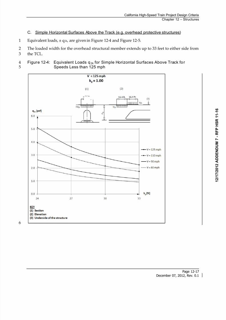
C. Simple Horizontal Surfaces Above the Track (e.g. overhead protective structures)
Equivalent loads, ± q2k , are given in Figure 12-4 and Figure 12-5.1
The loaded width for the overhead structural member extends up to 33 feet to either side from2
the TCL.3Figure 12-4: Equivalent Loads q2k for Simple Horizontal Surfaces Above Track fo r4
Speeds Less than 125 mph5
6
8/13/2019 California High-Speed Train Project Design Criteria
http://slidepdf.com/reader/full/california-high-speed-train-project-design-criteria 26/116
California High-Speed Train Project Design Criteria
Chapter 12 – Structures
Page 12-18December 07, 2012, Rev. 0.1
Figure 12-5: Equivalent Loads q2k for Simple Horizontal Surfaces Above Track fo r1Speeds Greater than 125 mph2
3
4
For trains passing in opposite directions, the actions shall be added. The loading from trains on5
only two tracks shall be considered.6
The actions q2k may be reduced by the factor k1 as defined in Section 12.5.2.7-B.7
The actions acting on the edge strips of a wide structure (greater than 33 feet) crossing the track8
may be multiplied by a factor of 0.75 over a width up to 16.5 feet.9
10
8/13/2019 California High-Speed Train Project Design Criteria
http://slidepdf.com/reader/full/california-high-speed-train-project-design-criteria 27/116
California High-Speed Train Project Design Criteria
Chapter 12 – Structures
Page 12-19December 07, 2012, Rev. 0.1
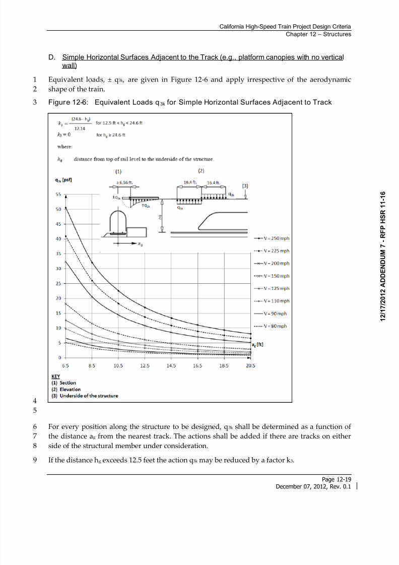
D. Simple Horizontal Surfaces Adjacent to the Track (e.g., platform canopies with no verticalwall)
Equivalent loads, ± q3k , are given in Figure 12-6 and apply irrespective of the aerodynamic1
shape of the train.2
Figure 12-6: Equivalent Loads q3k for Simple Horizontal Surfaces Adjacent to Track3
4
5
For every position along the structure to be designed, q3k shall be determined as a function of6
the distance ag from the nearest track. The actions shall be added if there are tracks on either7
side of the structural member under consideration.8
If the distance hg exceeds 12.5 feet the action q3k may be reduced by a factor k3.9
8/13/2019 California High-Speed Train Project Design Criteria
http://slidepdf.com/reader/full/california-high-speed-train-project-design-criteria 28/116
California High-Speed Train Project Design Criteria
Chapter 12 – Structures
Page 12-20December 07, 2012, Rev. 0.1
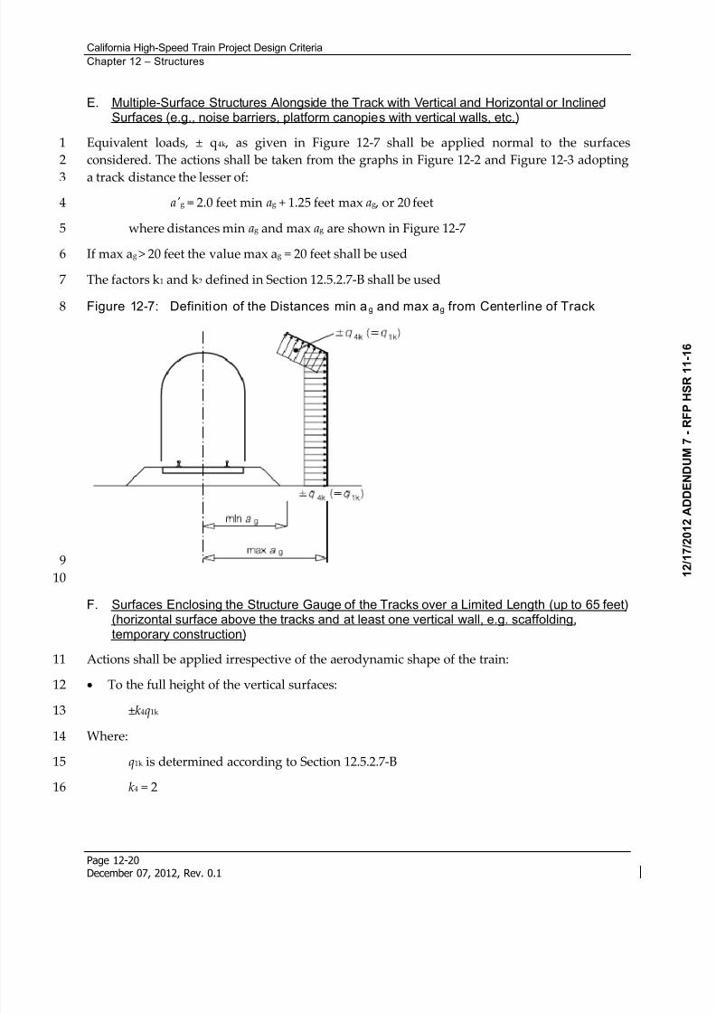
E. Multiple-Surface Structures Alongside the Track with Vertical and Horizontal or InclinedSurfaces (e.g., noise barriers, platform canopies with vertical walls, etc.)
Equivalent loads, ± q4k , as given in Figure 12-7 shall be applied normal to the surfaces1
considered. The actions shall be taken from the graphs in Figure 12-2 and Figure 12-3 adopting2
a track distance the lesser of:3
a'g = 2.0 feet min ag + 1.25 feet max ag , or 20 feet4
where distances min ag and max ag are shown in Figure 12-75
If max ag > 20 feet the value max ag = 20 feet shall be used6
The factors k1 and k2 defined in Section 12.5.2.7-B shall be used7
Figure 12-7: Definition of the Distances min ag and max ag from Centerline of Track8
9
10
F. Surfaces Enclosing the Structure Gauge of the Tracks over a Limited Length (up to 65 feet)(horizontal surface above the tracks and at least one vertical wall, e.g. scaffolding,temporary construction)
Actions shall be applied irrespective of the aerodynamic shape of the train:11
To the full height of the vertical surfaces:12
±k4q1k 13
Where:14
q1k is determined according to Section 12.5.2.7-B15
k4 = 216
8/13/2019 California High-Speed Train Project Design Criteria
http://slidepdf.com/reader/full/california-high-speed-train-project-design-criteria 29/116
California High-Speed Train Project Design Criteria
Chapter 12 – Structures
Page 12-21December 07, 2012, Rev. 0.1
To the horizontal surfaces:1
±k5q2k 2
Where:3
q2k is determined according to Section 12.5.2.7-C for only one track,4
k5 = 2.5 if one track is enclosed5
k5 = 3.5 if two tracks are enclosed6
G. Surfaces Perpendicular to or Crossing the Tracks over a Limited Length
Surfaces that are normal to the track such as wayside equipment and signs shall be designed to7
resist transient air pressure presented in Figure 12-2 and Figure 12-3 on vertical surfaces and8
Figure 12-4 and Figure 12-5 on horizontal surfaces.9
12.5.2.8 Thermal Load (TU, TG)
For uniform (TU) and gradient (TG) temperature effects of the structure, the requirements in10
AASHTO LRFD with Caltrans Amendments Article 3.12 shall be used. Consideration shall be11
given to the maximum and minimum ambient temperatures.12
12.5.2.9 Fric tional Force (FR)
The force due to friction (FR) shall be established on the basis of extreme values of the friction13
coefficient between sliding surfaces (i.e., at bearing pads). Where appropriate, the effects of14
moisture, degradation, and contamination of sliding or rotating surfaces upon the friction15
coefficient shall be considered.16
Where applicable, recommended frictional values per AASHTO LRFD with Caltrans17
Amendments shall be used.18
12.5.2.10 Seismic Loads (MCE, OBE)
Detailed, project specific seismic design criteria are presented in the Seismic chapter. The Seismic19
chapter defines seismic design philosophies, seismic analysis/demand methodologies, and20
structural capacity evaluation procedures for the two levels of design earthquakes.21
Primary structures shall comply with two performance levels.22
12.5.2.11 Hydrodynamic Force (WAD)
Hydrodynamic pressure effects acting on submerged portions of structures due to dynamic23
motion shall be computed using the method of Goyal and Chopra or by equivalent means.24
For possible additional hydrodynamic force effects, see the Geotechnical reports described in25
the Geotechnical chapter.26
8/13/2019 California High-Speed Train Project Design Criteria
http://slidepdf.com/reader/full/california-high-speed-train-project-design-criteria 30/116
California High-Speed Train Project Design Criteria
Chapter 12 – Structures
Page 12-22December 07, 2012, Rev. 0.1
12.5.2.12 Dynamic Earth Pressures (ED)
Dynamic earth pressure due to seismic motion acting on retaining structures shall be computed1
using the methods presented in the Geotechnical chapter.2
12.5.2.13 Derailment Loads (DR)
A. LLRR and LLV
In the event of derailment, the damage to the bridge or aerial structure shall be minimal.3
Overturning or collapse of the structure shall not be allowed.4
The following design situations shall be considered:5
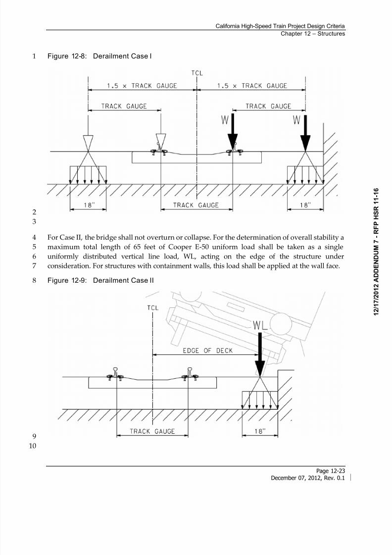
Case I – Derailment of railway vehicles, with the derailed vehicles remaining in the track6
area on the bridge deck with vehicles retained by the adjacent rail or a containment wall.7
Case II – Derailment of railway vehicles, with the derailed vehicles balanced on the edge of8
the bridge and loading the edge of the superstructure (excluding non-structural elements9
such as walkways).10
Case III – Derailment of a steel wheel impacting the bridge deck between containment11
barriers shall be evaluated using the heaviest axle loads that potentially use the structure12
with a minimum of the Cooper E-50. In shared use corridors, larger axle loads shall be13
considered with the larger axle loads. A 100 percent impact factor shall be applied. This14
force is used to design the concrete deck slab. See Item B of this section.15
Case IV – Derailment of railway vehicles on a through or semi-through type aerial structure16
or bridge shall be designed such that the sudden rupture of one vertical or diagonal member17
of the truss shall not cause collapse of the structure.18
For Case I, collapse of any part of the structure is not permitted. Local minor damage, however,19
is tolerated. The structure shall be designed for the following design loads in the Extreme20
Loading Combination:21
Cooper E-50 loading, (both point loads W and uniformly distributed loading w) parallel to22
the track in the most unfavorable position inside an area of width 1.5 times the track gauge23
on either side of the TCL, or as limited by containment walls. If a short containment wall is24
used for containment of the train within 1.5 times the track gauge, a coincident horizontal25
load perpendicular to the track direction shall be used. This horizontal load shall be applied26
at the top of the containment wall.27
8/13/2019 California High-Speed Train Project Design Criteria
http://slidepdf.com/reader/full/california-high-speed-train-project-design-criteria 31/116
California High-Speed Train Project Design Criteria
Chapter 12 – Structures
Page 12-23December 07, 2012, Rev. 0.1
Figure 12-8: Derailment Case I1
2
3
For Case II, the bridge shall not overturn or collapse. For the determination of overall stability a4
maximum total length of 65 feet of Cooper E-50 uniform load shall be taken as a single5
uniformly distributed vertical line load, WL, acting on the edge of the structure under6
consideration. For structures with containment walls, this load shall be applied at the wall face.7
Figure 12-9: Derailment Case II8
9
10
8/13/2019 California High-Speed Train Project Design Criteria
http://slidepdf.com/reader/full/california-high-speed-train-project-design-criteria 32/116
California High-Speed Train Project Design Criteria
Chapter 12 – Structures
Page 12-24December 07, 2012, Rev. 0.1
Cases I and II shall be examined separately. A combination of these loads need not be1
considered.2
For ballasted track, lateral distribution of wheel load may be applied, as shown in Figure 12-83
and Figure 12-9.4
For Cases I and II, other rail traffic actions shall be neglected for the track subjected to5
derailment actions. When the structure under consideration carries more than 1 track, only 16
train shall be considered to have derailed, with other tracks containing a vehicle without impact7
if producing an unfavorable action. Multiple live load presence factors shall apply in this case.8
No dynamic factor needs to be applied to the derailment loads for Case 1 and Case II. However,9
the loads shall be multiplied by the load factor within load combinations. A load factor of 1.010
shall apply to Case III and Case IV.11
B. Track Side Containment
Containment walls shall be provided on mainline aerial structures at locations 6 feet minimum12to 7 feet maximum from TCL toward the outside edge of deck. The height of the wall shall be13
minimum 0.67 feet above the level of the adjacent track’s lower rail. The containment walls shall14
terminate at the back of abutment backwalls. A transverse horizontal concentrated load of 3515
kips shall be applied at top of the wall at any point of contact. The load shall be distributed over16
a longitudinal length of 1 foot. A load factor of 1.4 shall be applied to the 35-kip load.17
12.5.2.14 Collision Loads (CL)
Collision loads in Sections 12.5.2.14-A, 12.5.2.14-B, and 12.5.2.14-C apply to train impact loads18
(LLRR, LLV). Section 12.5.2.14-D applies to highway collision loads (LLH). For collision loads19
on columns or divider walls within the trackway, reference Section 12.7 - Structural Design of20Surface Facilities and Buildings.21
A. Collision Loads other than at Stations or Platforms
Unprotected structural members within 25 feet of the TCL shall be designed to resist train22
collision forces of 900 kips parallel and 400 kips perpendicular to the tracks. The loads are23
applied to a strip 6 feet in length and at a height centered 4 feet above grade. Forces are not24
applied simultaneously.25
B. Collision Loads on Separation Barriers to Deter Intrusion of Derailed Freight/PassengerTrains
The height of barrier wall shall be as shown in the Rolling Stock and Vehicle Intrusion Protection 26chapter. The wall shall be constructed of reinforced concrete. The wall shall extend 15 feet27
beyond each end of the pier or a wall that is within 25 feet of the TCL, and shall conform to the28
end conditions presented in the Rolling Stock and Vehicle Intrusion Protection chapter.29
A moving load of 400 kips transverse to the TCL applied to a strip 6 feet in length at and height30
centered 4 feet above ground level. A 900 kip longitudinal force shall be applied to the wall at31
the same elevation. Loads are not applied simultaneously.32
8/13/2019 California High-Speed Train Project Design Criteria
http://slidepdf.com/reader/full/california-high-speed-train-project-design-criteria 33/116
California High-Speed Train Project Design Criteria
Chapter 12 – Structures
Page 12-25December 07, 2012, Rev. 0.1
C. Structures in Areas beyond Track Ends
Overrunning of rail traffic beyond the end of a track (for example at a terminal station) shall be1
taken into account as an accidental design situation when the structure or its supports are2
located in the area immediately beyond the track ends.3
The measures to manage the risk shall be based on the utilization of the area immediately4
beyond the track end and take into account any measures taken to reduce the likelihood of an5
overrun of rail traffic.6
Members supporting structures shall not be located in the area immediately beyond the track7
ends.8
Where structural supporting members are required to be located near to track ends, an end9
impact wall shall be provided within 20 feet of the track ends in addition to any buffer stop.10
The design values for the static equivalent force due to impact on the end impact wall are Fdx =11
1125 kips for passenger trains and Fdx = 2250 kips for freight trains or heavy engines pulling12conventional passenger cars. It is recommended that these forces be applied horizontally to a 6-13
foot wide strip at a level of 4 feet above track level.14
D. Highway Vehicle Collision Loads (LLH)
Highway collision load shall be as per AASHTO LRFD with Caltrans Amendments Article 3.6.5.15
12.5.3 Miscellaneous Loads
12.5.3.1 Loads and Load Combinations for Design of the Surrounding Area of theEmbedded Sleeves of Overhead Contact System Pole Foundation
The embedded sleeves as specified in the Table 12-2 for the OCS pole and down guy anchors in16
the outside compartment of the cable trough on both sides of structural deck shall be installed17
at an equal spacing not more than 30 feet in each span along the aerial structure and the offset18
distance from the centerline of the pier to the centerline of sleeve pattern shall be equal to 1/2 of19
the equal spacing. If this requirement results in a location within 6 feet of a bridge expansion20
joint, the location shall be adjusted to provide a spacing of no more than 30 feet to the adjacent21
OCS foundation anchor point. The loads, load combinations, and limit states specified in Table22
12-2 shall be investigated for design of the surrounding area of the embedded sleeves at every23
OCS foundation to properly transfer the loads to the bridge deck.24
8/13/2019 California High-Speed Train Project Design Criteria
http://slidepdf.com/reader/full/california-high-speed-train-project-design-criteria 34/116
California High-Speed Train Project Design Criteria
Chapter 12 – Structures
Page 12-26December 07, 2012, Rev. 0.1
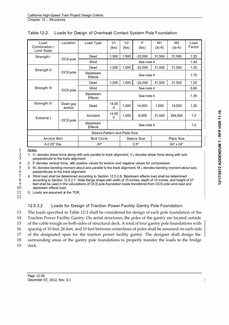
Table 12-2: Loads for Design of Overhead Contact System Pole Foundation
LoadCombination /
Limit State
Location Load Type V1
(lbs)
V2
(lbs)
P
(lbs)
M1
(lb-ft)
M2
(lb-ft)
LoadFactor
Strength I OCS pole Dead 1,500 1,500 -22,000 31,500 31,500 1.25 Wind See note 4 1.40
Strength II OCS pole
Dead 1,500 1,500 -22,000 31,500 31,500 1.25
SlipstreamEffects
See note 4 1.75
Strength III OCS pole
Dead 1,500 1,500 -22,000 31,500 31,500 1.25
Wind See note 4 0.65
SlipstreamEffects
See note 4 1.35
Strength IV Down guyanchor
Dead 14,00
0 1,000 14,000 1,000 14,000 1.25
Extreme I OCS pole
Accident 14,000
1,500 -8,000 31,500 294,000 1.0
SlipstreamEffects
See note 4 1.0
Sleeve Pattern and Plate Size
Anchor Bol t Bolt Circ le Sleeve Size Plate Size
4-2.25" Dia. 24" 2.5" 24" x 24"
Notes:11. V1 denotes shear force along with axis parallel to track alignment; V2 denotes shear force along with axis2
perpendicular to the track alignment.32. P denotes vertical force, with positive values for tension and negative values for compression.43. M1 denotes bending moment about axis parallel to the track alignment; M 2 denotes bending moment about axis5
perpendicular to the track alignment.64. Wind load shall be determined according to Section 12.5.2.6; Slipstream effects load shall be determined7
according to Section 12.5.2.7. Wide flange shape with width of 15 inches, depth of 15 inches, and height of 278feet shall be used in the calculations of OCS pole foundation loads transferred from OCS pole wind load and9slipstream effects load.10
5. Loads are assumed at the TOR.1112
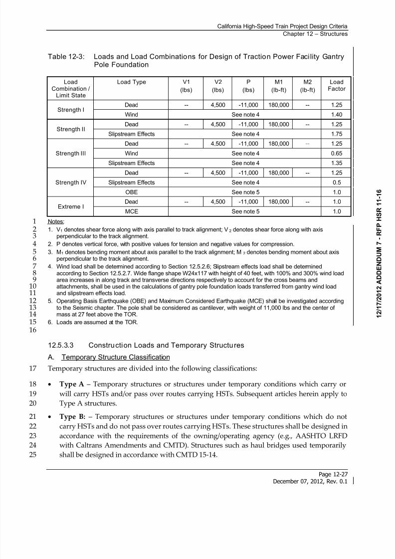
12.5.3.2 Loads for Design of Traction Power Facility Gantry Pole Foundation
The loads specified in Table 12-3 shall be considered for design of each pole foundation of the13
Traction Power Facility Gantry. On aerial structures, the poles of the gantry are located outside14
of the cable trough on both sides of structural deck. A total of four gantry pole foundations with15
spacing of 10 feet, 26 feet, and 10 feet between centerlines of poles shall be assumed on each side16of the designated span for the traction power facility gantry. The designer shall design the17
surrounding areas of the gantry pole foundations to properly transfer the loads to the bridge18
deck.19
8/13/2019 California High-Speed Train Project Design Criteria
http://slidepdf.com/reader/full/california-high-speed-train-project-design-criteria 35/116
California High-Speed Train Project Design Criteria
Chapter 12 – Structures
Page 12-27December 07, 2012, Rev. 0.1
Table 12-3: Loads and Load Combinations for Design of Traction Power Faci lity GantryPole Foundation
LoadCombination /
Limit State
Load Type V1
(lbs)
V2
(lbs)
P
(lbs)
M1
(lb-ft)
M2
(lb-ft)
LoadFactor
Strength I Dead -- 4,500 -11,000 180,000 -- 1.25
Wind See note 4 1.40
Strength II Dead -- 4,500 -11,000 180,000 -- 1.25
Slipstream Effects See note 4 1.75
Strength III
Dead -- 4,500 -11,000 180,000 -- 1.25
Wind See note 4 0.65
Slipstream Effects See note 4 1.35
Strength IV
Dead -- 4,500 -11,000 180,000 -- 1.25
Slipstream Effects See note 4 0.5
OBE See note 5 1.0
Extreme I Dead -- 4,500 -11,000 180,000 -- 1.0
MCE See note 5 1.0
Notes:11. V1 denotes shear force along with axis parallel to track alignment; V2 denotes shear force along with axis2
perpendicular to the track alignment.32. P denotes vertical force, with positive values for tension and negative values for compression.43. M1 denotes bending moment about axis parallel to the track alignment; M 2 denotes bending moment about axis5
perpendicular to the track alignment.64. Wind load shall be determined according to Section 12.5.2.6; Slipstream effects load shall be determined7
according to Section 12.5.2.7. Wide flange shape W24x117 with height of 40 feet, with 100% and 300% wind load8area increases in along track and transverse directions respectively to account for the cross beams and9attachments, shall be used in the calculations of gantry pole foundation loads transferred from gantry wind load10
and slipstream effects load.115. Operating Basis Earthquake (OBE) and Maximum Considered Earthquake (MCE) shall be investigated according12
to the Seismic chapter. The pole shall be considered as cantilever, with weight of 11,000 lbs and the center of13mass at 27 feet above the TOR.14
6. Loads are assumed at the TOR.1516
12.5.3.3 Construction Loads and Temporary Structures
A. Temporary Structure Classification
Temporary structures are divided into the following classifications:17
Type A – Temporary structures or structures under temporary conditions which carry or18
will carry HSTs and/or pass over routes carrying HSTs. Subsequent articles herein apply to19Type A structures.20
Type B: – Temporary structures or structures under temporary conditions which do not21
carry HSTs and do not pass over routes carrying HSTs. These structures shall be designed in22
accordance with the requirements of the owning/operating agency (e.g., AASHTO LRFD23
with Caltrans Amendments and CMTD). Structures such as haul bridges used temporarily24
shall be designed in accordance with CMTD 15-14.25
8/13/2019 California High-Speed Train Project Design Criteria
http://slidepdf.com/reader/full/california-high-speed-train-project-design-criteria 36/116
California High-Speed Train Project Design Criteria
Chapter 12 – Structures
Page 12-28December 07, 2012, Rev. 0.1
For earth retaining structures and underground structures, see requirements in the Geotechnical 1
chapter.2
B. Construction Load Combinations
Type A temporary structures or structures under temporary conditions shall be designed to3 adequately resist conditions at all stages of construction, including applicable construction4
loads. Construction load combinations, in addition to requirements of Table 12-4, shall include5
the following:6
Applicable strength load combinations: Dead load factors shall not be taken less than 1.25,7
with construction dead loads taken as permanent loads. Construction transient live load8
factors shall not be taken less than 1.5. Wind load factors may be reduced by 20 percent.9
Service 1, as applicable, see AASHTO LRFD Article 3.4.2.10
Seismic requirements for temporary structures are presented in the Seismic chapter.11
In the absence of specific criteria, a construction live load of 20 psf shall be assumed on the12
bridge deck.13
C. Segmental Construction and Specialized Equipment
Construction load combinations per AASHTO LRFD with Caltrans Amendments Article 5.14.214
“Segmental Construction” shall be considered. The temporary seismic load event as described15
in the Seismic chapter shall be added to the construction load combination at Strength 5 limit16
state; however a 1.25 load factor shall be used for dead and live loads. The temporary seismic17
event need not be combined with the dynamic construction load impact due to segment drop or18
equipment impact. For balanced cantilever construction methods an additional 2 percent of19
dead load shall be applied to reflect eccentric conditions at the time of a potential seismic event.20
12.5.3.4 Track-Structure Interaction Forces
Effects of continuous welded rail (CWR) interaction with the structure through its attachment21
shall be considered. Design guidance and requirements for this interaction is provided in22
Section 12.6 - Track-Structure Interaction.23
12.5.3.5 Blast Loading
Blast loadings and measures are not specified at this time. See Section 12.13 for general24
requirements. Refer to AASHTO LRFD with Caltrans Amendments Article 3.15 for aerial25
structure requirements.26
12.5.4 Load Factors and Load Modifiers
Regardless of the type of analysis used, the Eq. 12.5.4-1 shall be satisfied for specified factored27
force effect and load combinations for each limit state unless otherwise specified in the section:28
i i Qi Rn = Rr (Eq. 12.5.4-1)29
8/13/2019 California High-Speed Train Project Design Criteria
http://slidepdf.com/reader/full/california-high-speed-train-project-design-criteria 37/116
California High-Speed Train Project Design Criteria
Chapter 12 – Structures
Page 12-29December 07, 2012, Rev. 0.1
Where:1
i = load factor applied to force effects (see Tables 12-4, 12-6 and 12-7)2
= resistance factor applied to nominal resistance (see AASHTO LRFD with3
Caltrans Amendments Article 1.3.2.1)4
i = load modifier relating to ductility, redundancy and importance (see AASHTO5
LRFD with Caltrans Amendments Article 1.3.2.1)6
Qi = force effect7
Rn = nominal resistance8
Rr = factored resistance, Rn9
For loads in which a maximum value of “i” produces an unfavorable action, the value of “i”10
shall be equal to 1.05 to account for the design life of the facility. The load modifier is applicable11
to Strength Limit Load Combinations only.12
12.5.4.1 Design Load Combinations
The load combinations to be used for structures carrying HSTs are presented in Table 12-4. The13
description of the load combinations are as follows:14
”Strength 1” is the basic load combination for normal use.15
”Strength 2” is the load combination for the structure exposed to wind.16
“Strength 3” is the load combination for very high dead load to live load force effect ratios.17
“Strength 4” is the load combination for normal use when exposed to wind.18
“Strength 5” is the load combination for normal use when designing columns for OBE.19
“Extreme 1” is the load combination for derailment.20
“Extreme 2” is the load combination for collision.21
“Extreme 3” is the load combination for extreme seismic events: MCE.22
”Service 1” is the basic service load combination for normal use with wind.23
”Service 2” is the service load combination intended to control yielding of steel structures24
and slip of slip-critical connections due to train load.25
”Service 3” is the service load combination relating to tension in prestressed concrete26 superstructures with the objective of crack control and principal tension in the webs of27
segmental concrete girders.28
“Buoyancy at Dewatering Shutoff” is a service load for evaluation of uplift with a minimum29
weight structure.30
“Fatigue” is the fatigue and fracture load combination relating to repetitive vertical train31
loading.32
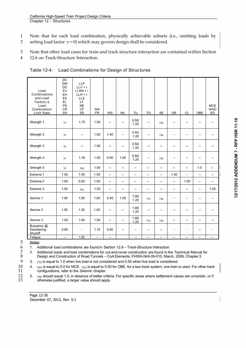
8/13/2019 California High-Speed Train Project Design Criteria
http://slidepdf.com/reader/full/california-high-speed-train-project-design-criteria 38/116
California High-Speed Train Project Design Criteria
Chapter 12 – Structures
Page 12-30December 07, 2012, Rev. 0.1
Note that for each load combination, physically achievable subsets (i.e., omitting loads by1
setting load factor i = 0) which may govern design shall be considered.2
Note that other load cases for train and track structure interaction are contained within Section3
12.6 on Track-Structure Interaction.4
Table 12-4: Load Combinations for Design of Structures
LoadCombinations
and Load
Factors, i
LoadCombination/
Limit State
DC
DWDDEV
EHESEL
PSCRSH
LLPLLV + I
LLRR + ILLH + I
LLSLF
NECFSS
WAFR WS WL TU TG SE DR CL OBE
MCEWADED
Strength 1 P 1.75 1.00 -- -- 0.50/1.20 -- SE -- -- -- --
Strength 2 P -- 1.00 1.40 --0.50/1.20
-- SE -- -- -- --
Strength 3 P -- 1.00 -- --0.50/1.20
-- -- -- -- -- --
Strength 4 P 1.35 1.00 0.65 1.000.50/1.20
-- SE -- -- -- --
Strength 5 P EQ 1.00 -- -- -- -- -- -- -- 1.0 --
Extreme 1 1.00 1.00 1.00 -- -- -- -- -- 1.40 -- -- --
Extreme 2 1.00 0.50 1.00 -- -- -- -- -- -- 1.00 -- --
Extreme 3 1.00 EQ 1.00 -- -- -- -- -- -- -- -- 1.00
Service 1 1.00 1.00 1.00 0.45 1.001.00/1.20
TG SE -- -- -- --
Service 2 1.00 1.30 1.00 -- -- 1.00/1.20
-- -- -- -- -- -- Service 3 1.00 1.00 1.00 -- --
1.00/1.20
TG SE -- -- -- -- Buoyancy @DewateringShutoff
0.80 -- 1.10 0.45 -- -- -- -- -- -- -- --
Fatigue -- 1.00 -- -- -- -- -- -- -- -- --
Notes:5 1. Additional load combinations are found in Section 12.6 – Track-Structure Interaction62. Additional loads and load combinations for cut-and-cover construction are found in the Technical Manual for7
Design and Construction of Road Tunnels – Civil Elements; FHWA-NHI-09-010, March, 2009, Chapter 583. TG is equal to 1.0 when live load is not considered and 0.50 when live load is considered.94. EQ is equal to 0.0 for MCE. EQ is equal to 0.50 for OBE, for a two track system, one train is used. For other track10
configurations, refer to the Seismic chapter.115. SE should equal 1.0, in absence of better criteria. For specific areas where settlement values are uncertain, or if12
otherwise justified, a larger value should apply.13
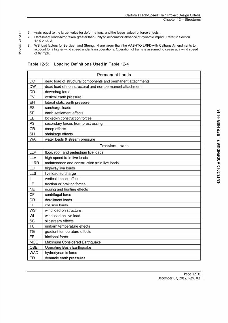
8/13/2019 California High-Speed Train Project Design Criteria
http://slidepdf.com/reader/full/california-high-speed-train-project-design-criteria 39/116
California High-Speed Train Project Design Criteria
Chapter 12 – Structures
Page 12-31December 07, 2012, Rev. 0.1
6. TU is equal to the larger value for deformations, and the lesser value for force effects.17. Derailment load factor taken greater than unity to account for absence of dynamic impact. Refer to Section2
12.5.2.13- A.38. WS load factors for Service I and Strength 4 are larger than the AASHTO LRFD with Caltrans Amendments to4
account for a higher wind speed under train operations. Operation of trains is assumed to cease at a wind speed5of 67 mph.6
Table 12-5: Loading Definit ions Used in Table 12-4
Permanent Loads
DC dead load of structural components and permanent attachments
DW dead load of non-structural and non-permanent attachment
DD downdrag force
EV vertical earth pressure
EH lateral static earth pressure
ES surcharge loads
SE earth settlement effectsEL locked-in construction forces
PS secondary forces from prestressing
CR creep effects
SH shrinkage effects
WA water loads & stream pressure
Transient Loads
LLP floor, roof, and pedestrian live loads
LLV high-speed train live loads
LLRR maintenance and construction train live loads
LLH highway live loadsLLS live load surcharge
I vertical impact effect
LF traction or braking forces
NE nosing and hunting effects
CF centrifugal force
DR derailment loads
CL collision loads
WS wind load on structure
WL wind load on live load
SS slipstream effects
TU uniform temperature effectsTG gradient temperature effects
FR frictional force
MCE Maximum Considered Earthquake
OBE Operating Basis Earthquake
WAD hydrodynamic force
ED dynamic earth pressures
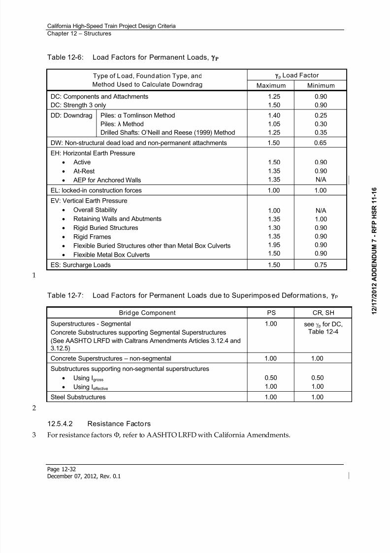
8/13/2019 California High-Speed Train Project Design Criteria
http://slidepdf.com/reader/full/california-high-speed-train-project-design-criteria 40/116
California High-Speed Train Project Design Criteria
Chapter 12 – Structures
Page 12-32December 07, 2012, Rev. 0.1
Table 12-6: Load Factors for Permanent Loads, P
Type of Load, Foundation Type, and
Method Used to Calculate Downdrag
p Load Factor
Maximum Minimum
DC: Components and AttachmentsDC: Strength 3 only
1.251.50
0.900.90
DD: Downdrag Piles: Tomlinson Method
Piles: Method
Drilled Shafts: O’Neill and Reese (1999) Method
1.40
1.05
1.25
0.25
0.30
0.35
DW: Non-structural dead load and non-permanent attachments 1.50 0.65
EH: Horizontal Earth Pressure
Active
At-Rest
AEP for Anchored Walls
1.50
1.35
1.35
0.90
0.90
N/A
EL: locked-in construction forces 1.00 1.00EV: Vertical Earth Pressure
Overall Stability
Retaining Walls and Abutments
Rigid Buried Structures
Rigid Frames
Flexible Buried Structures other than Metal Box Culverts
Flexible Metal Box Culverts
1.00
1.35
1.30
1.35
1.95
1.50
N/A
1.00
0.90
0.90
0.90
0.90
ES: Surcharge Loads 1.50 0.75
1
Table 12-7: Load Factors for Permanent Loads due to Superimposed Deformations, P
Bridge Component PS CR, SH
Superstructures - Segmental
Concrete Substructures supporting Segmental Superstructures
(See AASHTO LRFD with Caltrans Amendments Articles 3.12.4 and3.12.5)
1.00 see p for DC,Table 12-4
Concrete Superstructures – non-segmental 1.00 1.00
Substructures supporting non-segmental superstructures
Using Igross
Using Ieffective
0.50
1.00
0.50
1.00Steel Substructures 1.00 1.00
2
12.5.4.2 Resistance Factors
For resistance factors , refer to AASHTO LRFD with California Amendments.3
8/13/2019 California High-Speed Train Project Design Criteria
http://slidepdf.com/reader/full/california-high-speed-train-project-design-criteria 41/116
California High-Speed Train Project Design Criteria
Chapter 12 – Structures
Page 12-33December 07, 2012, Rev. 0.1
12.6 Track-Structure Interaction
Bridges and aerial structures that support high-speed trains are subject to structural frequency1
limits, track serviceability limits, rail-structure interaction limits, dynamic structural analysis2
limits, and dynamic vehicle track-structure interaction analysis limits.3
These requirements are concerned with limiting bridge and aerial structure deformations and4
accelerations, since the structure response can be dynamically magnified under high-speed5
moving trains. Excessive deformations and accelerations can lead to unacceptable changes in6
vertical and horizontal track geometry, excessive rail stress, reduction in wheel contact,7
dynamic amplification of loads, and passenger discomfort.8
Track-structure interaction criteria shall apply to any aerial structure whose primary function is9
to support high-speed train (HST) tracks and therefore critical to track performance. These10
aerial structures include, but are not limited to: bridges, grade separations, stream crossings,11
canal crossings, culverts with less than 6 feet of cover, viaducts, and aerial stations supporting12
HST tracks. For a given aerial structure, all structural discontinuities capable of relative13
movement shall be considered a structural expansion joint and subject to the applicable criteria.14
For criteria related to embankments, abutments, retaining walls, and soil subgrades critical for15
ensuring track performance, see the Geotechnical chapter. For criteria related to track16
performance in tunnels, see Tunnels chapter. Track support discontinuities at transitions17
between aerial structures and geotechnical elements (including tunnels) shall be considered18
structural expansion joints and subject to the following applicable criteria.19
The following criteria is developed assuming uniform longitudinal rail restraint for structures20
with maximum structural thermal units (i.e., the maximum distance from a fixed point of21 thermal expansion to an adjacent fixed point of thermal expansion on a structure) limited to 33022
feet. Rail expansion joints are not permitted without an approved design variance.23
Table 12-8 summarizes the analysis requirements, including model type, train model/speed,24
result, and relevant section.25
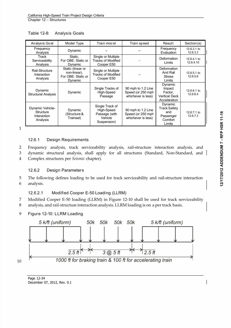
8/13/2019 California High-Speed Train Project Design Criteria
http://slidepdf.com/reader/full/california-high-speed-train-project-design-criteria 42/116
California High-Speed Train Project Design Criteria
Chapter 12 – Structures
Page 12-34December 07, 2012, Rev. 0.1
Table 12-8: Analysis Goals
Analys is Goal Model Type Train model Train speed Resul t Section (s)
Frequency Analysis
Dynamic -- --FrequencyEvaluation
12.6.3.1 to12.6.3.3
TrackServiceability
Analysis
Static,For OBE: Static or
Dynamic
Single or MultipleTracks of Modified
Cooper E50--
DeformationLimits
12.6.4.1 to12.6.4.10
Rail-StructureInteraction Analysis
Static (linear ornon-linear),
For OBE: Static orDynamic
Single or MultipleTracks of Modified
Cooper E50--
Deformation And Rail
StressLimits
12.6.5.1 to12.6.5.6
DynamicStructural Analysis
DynamicSingle Tracks of
High-SpeedPassage
90 mph to 1.2 LineSpeed (or 250 mphwhichever is less)
DynamicImpactFactor,
Vertical Deck Acceleration
12.6.6.1 to12.6.6.4
Dynamic Vehicle-Structure
Interaction Analysis
Dynamic
(Structure &Trainset)
Single Track ofHigh-Speed
Passage (withVehicleSuspension)
90 mph to 1.2 Line
Speed (or 250 mphwhichever is less)
DynamicTrack Safety
and
PassengerComfortLimits
12.6.7.1 to
12.6.7.3
1
12.6.1 Design Requirements
Frequency analysis, track serviceability analysis, rail-structure interaction analysis, and2
dynamic structural analysis, shall apply for all structures (Standard, Non-Standard, and3
Complex structures per Seismic chapter).4
12.6.2 Design ParametersThe following defines loading to be used for track serviceability and rail-structure interaction5
analysis.6
12.6.2.1 Modified Cooper E-50 Loading (LLRM)
Modified Cooper E-50 loading (LLRM) in Figure 12-10 shall be used for track serviceability7
analysis, and rail-structure interaction analysis. LLRM loading is on a per track basis.8
Figure 12-10: LLRM Loading9
10
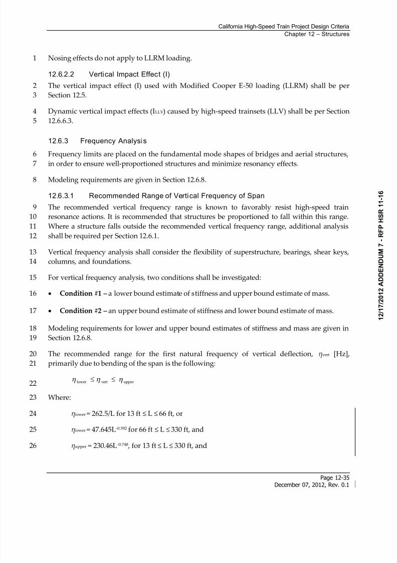
8/13/2019 California High-Speed Train Project Design Criteria
http://slidepdf.com/reader/full/california-high-speed-train-project-design-criteria 43/116
California High-Speed Train Project Design Criteria
Chapter 12 – Structures
Page 12-35December 07, 2012, Rev. 0.1
Nosing effects do not apply to LLRM loading.1
12.6.2.2 Vertical Impact Effect (I)
The vertical impact effect (I) used with Modified Cooper E-50 loading (LLRM) shall be per2
Section 12.5.3
Dynamic vertical impact effects (ILLV) caused by high-speed trainsets (LLV) shall be per Section4
12.6.6.3.5
12.6.3 Frequency Analysis
Frequency limits are placed on the fundamental mode shapes of bridges and aerial structures,6
in order to ensure well-proportioned structures and minimize resonancy effects.7
Modeling requirements are given in Section 12.6.8.8
12.6.3.1 Recommended Range of Vertical Frequency of SpanThe recommended vertical frequency range is known to favorably resist high-speed train9
resonance actions. It is recommended that structures be proportioned to fall within this range.10
Where a structure falls outside the recommended vertical frequency range, additional analysis11
shall be required per Section 12.6.1.12
Vertical frequency analysis shall consider the flexibility of superstructure, bearings, shear keys,13
columns, and foundations.14
For vertical frequency analysis, two conditions shall be investigated:15
Condition #1 – a lower bound estimate of stiffness and upper bound estimate of mass.16
Condition #2 – an upper bound estimate of stiffness and lower bound estimate of mass.17
Modeling requirements for lower and upper bound estimates of stiffness and mass are given in18
Section 12.6.8.19
The recommended range for the first natural frequency of vertical deflection, vert [Hz],20
primarily due to bending of the span is the following:21
uppervertlower 22
Where:23
lower = 262.5/L for 13 ft L 66 ft, or24
lower = 47.645L-0.592 for 66 ft L 330 ft, and25
upper = 230.46L-0.748 , for 13 ft L 330 ft, and26
8/13/2019 California High-Speed Train Project Design Criteria
http://slidepdf.com/reader/full/california-high-speed-train-project-design-criteria 44/116
California High-Speed Train Project Design Criteria
Chapter 12 – Structures
Page 12-36December 07, 2012, Rev. 0.1
L = effective length of span (feet)1
For simple spans, L shall be the span length.2
For continuous spans, L shall be the following:3
average Lk L 4
Where:5
n
L L L L n )...( 21
average
= the average span length,6
n the number of spans7
5.1
10
1
n
k
8
For portal frames and closed frame bridges, L shall be the following:9
Single span: consider as three continuous spans, with the first and third span being the10
vertical length of the columns, and the second span the girder length.11
Multiple spans: consider as multiple spans, with the first and last span as the vertical length12
of the end columns, and the interior spans the girder lengths.13
For spans with end diaphragms at abutments (fixed supports at abutments):14
Single span, fixed at one abutment: consider as two continuous spans, with the first span15equal to 0.05 times the girder length, and the second span the girder length.16
Single span, fixed at both abutments: consider as three continuous spans, with the first and17
the third span equal to 0.05 times the girder length, and the second span the girder length.18
Multiple spans, fixed at one abutment: consider as multiple spans, with the first span equal19
to 0.05 times the adjacent girder length, and the interior spans the girder lengths.20
Multiple spans, fixed at both abutments: consider as multiple spans, with the first and last21
span equal to 0.05 times the adjacent girder length, and the interior spans the girder lengths.22
For single arch, archrib, or stiffened girders of bowstrings, L shall be the half span.23
See Figure 12-11 for the recommended range of vertical frequency.24
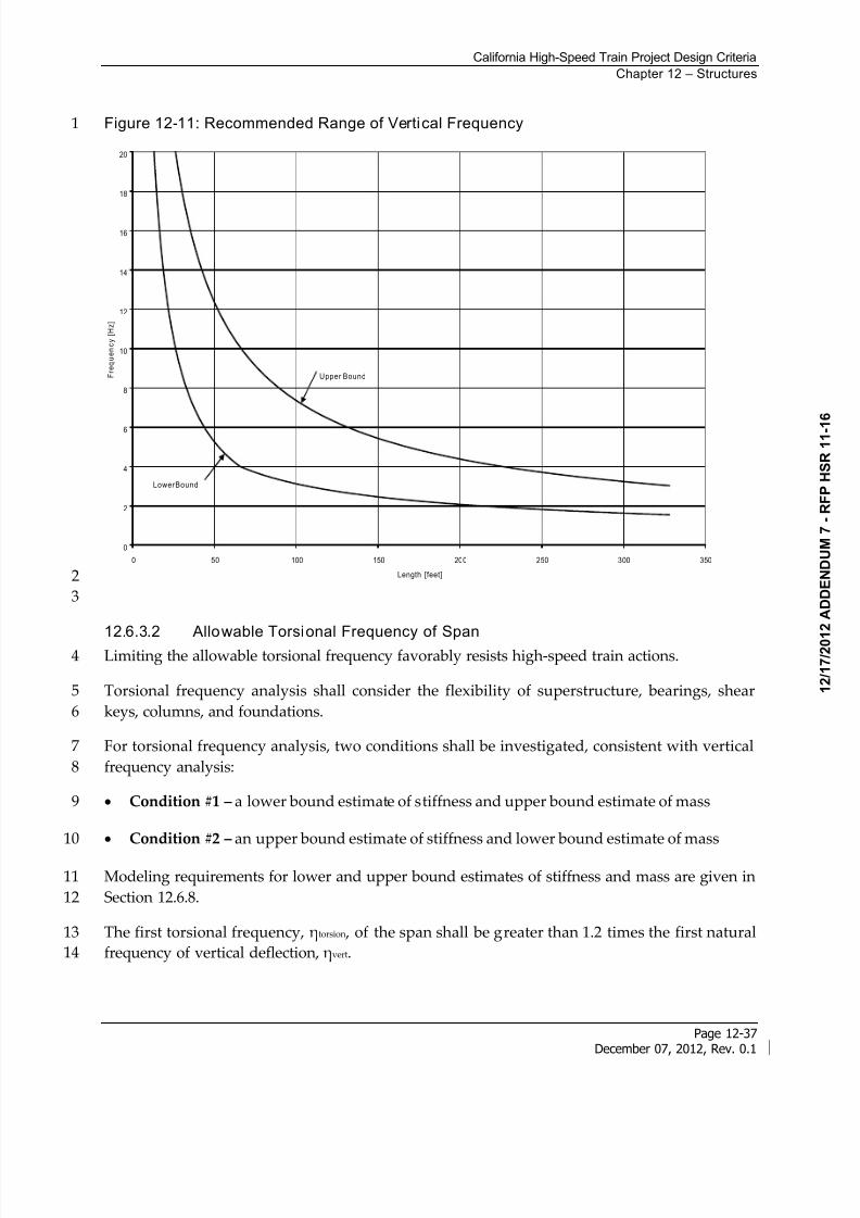
8/13/2019 California High-Speed Train Project Design Criteria
http://slidepdf.com/reader/full/california-high-speed-train-project-design-criteria 45/116
California High-Speed Train Project Design Criteria
Chapter 12 – Structures
Page 12-37December 07, 2012, Rev. 0.1
Figure 12-11: Recommended Range of Vertical Frequency1
0
2
4
6
8
10
12
14
16
18
20
0 50 100 150 200 250 300 350
Length [feet]
F r e q u e n c y
[ H
z ]
Upper Bound
LowerBound
2
3
12.6.3.2 Allowable Torsional Frequency of Span
Limiting the allowable torsional frequency favorably resists high-speed train actions.4
Torsional frequency analysis shall consider the flexibility of superstructure, bearings, shear5
keys, columns, and foundations.6
For torsional frequency analysis, two conditions shall be investigated, consistent with vertical7
frequency analysis:8
Condition #1 – a lower bound estimate of stiffness and upper bound estimate of mass9
Condition #2 – an upper bound estimate of stiffness and lower bound estimate of mass10
Modeling requirements for lower and upper bound estimates of stiffness and mass are given in11
Section 12.6.8.12
The first torsional frequency, torsion , of the span shall be greater than 1.2 times the first natural13
frequency of vertical deflection, vert.14
8/13/2019 California High-Speed Train Project Design Criteria
http://slidepdf.com/reader/full/california-high-speed-train-project-design-criteria 46/116
California High-Speed Train Project Design Criteria
Chapter 12 – Structures
Page 12-38December 07, 2012, Rev. 0.1
12.6.3.3 Allowable Transverse Frequency of Span
Limiting the allowable transverse frequency favorably resists high-speed train actions.1
Transverse frequency analysis shall consider the flexibility of superstructure only, excluding the2
flexibility of bearings, columns, and foundations, assuming the supports at the ends of the span3
are rigid.4
For transverse frequency analysis, a lower bound estimate of stiffness and upper bound5
estimate of mass shall be used, see Section 12.6.8.6
The first natural frequency of transverse deflection, trans , of the span shall not be less than 1.27
Hz.8
12.6.4 Track Serviceability Analysis
Track serviceability analysis, using modified Cooper E-50 loading, provides limits to allowable9
structural deformations. These track serviceability limits are developed for structures10supporting continuous welded rail without rail expansion joints.11
Deformation limits are developed for limit states based on maintenance, passenger comfort, and12
track safety requirements.13
For track serviceability analysis, the flexibility of superstructure and substructure (i.e: bearings,14
shear keys, columns, and foundations) shall be considered.15
To avoid underestimating deformations, a lower bound estimate of stiffness and an upper16
bound estimate of mass shall be used.17
Modeling requirements are given in Section 12.6.8.18
12.6.4.1 Track Serviceability Load Cases
Track serviceability loads cases shall include the following:19
Group 1a: (LLRM + I)1 20
Group 1b: (LLRM + I)2 + CF2 + WA21
Group 1c: (LLRM + I)m + CFm + WA22
Group 2: (LLRM + I)1 + CF1 + WA + WS + WL1 23
Group 3: (LLRM + I)1 + CF1 + OBE24
Where:25
(LLRM + I)1 = one track of Modified Cooper E-50 (LLRM) plus impact26
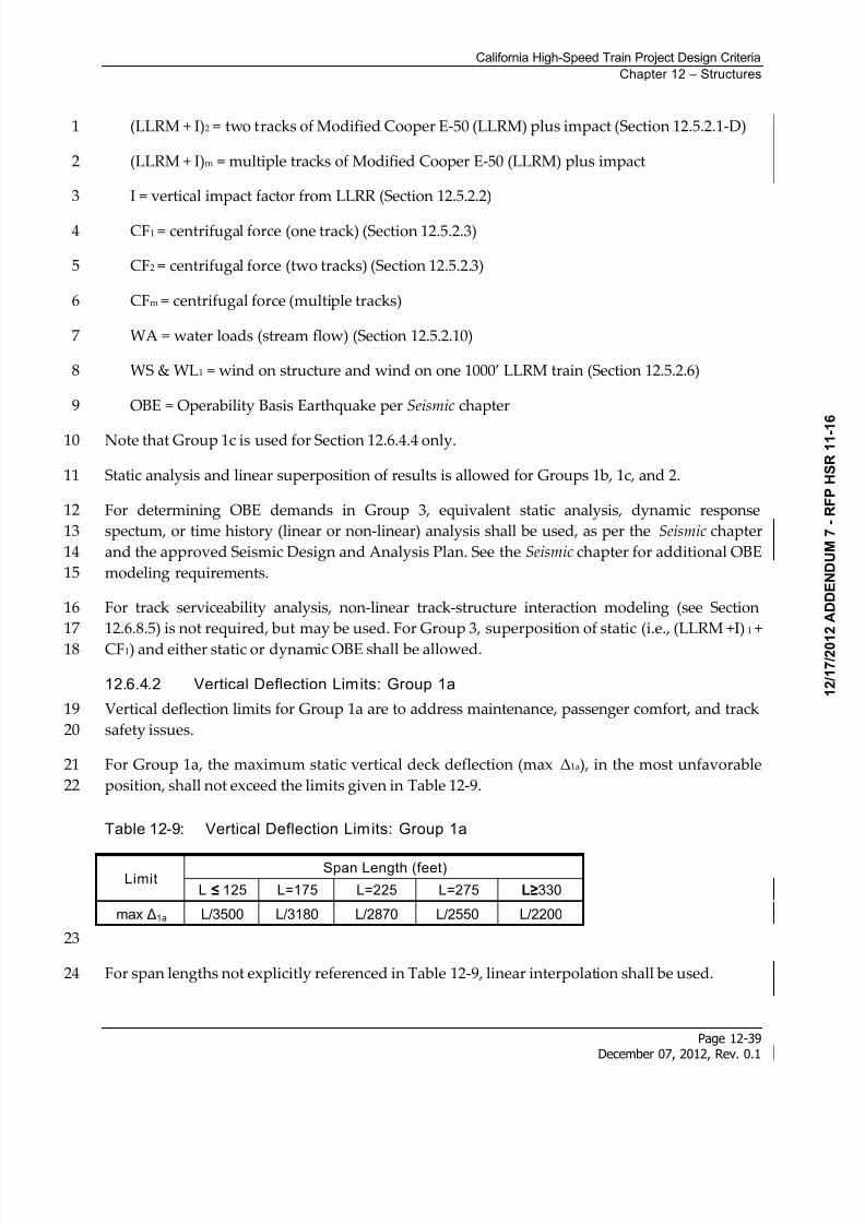
8/13/2019 California High-Speed Train Project Design Criteria
http://slidepdf.com/reader/full/california-high-speed-train-project-design-criteria 47/116
California High-Speed Train Project Design Criteria
Chapter 12 – Structures
Page 12-39December 07, 2012, Rev. 0.1
(LLRM + I)2 = two tracks of Modified Cooper E-50 (LLRM) plus impact (Section 12.5.2.1-D)1
(LLRM + I)m = multiple tracks of Modified Cooper E-50 (LLRM) plus impact2
I = vertical impact factor from LLRR (Section 12.5.2.2)3
CF1 = centrifugal force (one track) (Section 12.5.2.3)4
CF2 = centrifugal force (two tracks) (Section 12.5.2.3)5
CFm = centrifugal force (multiple tracks)6
WA = water loads (stream flow) (Section 12.5.2.10)7
WS & WL1 = wind on structure and wind on one 1000’ LLRM train (Section 12.5.2.6)8
OBE = Operability Basis Earthquake per Seismic chapter9
Note that Group 1c is used for Section 12.6.4.4 only.10
Static analysis and linear superposition of results is allowed for Groups 1b, 1c, and 2.11
For determining OBE demands in Group 3, equivalent static analysis, dynamic response12
spectum, or time history (linear or non-linear) analysis shall be used, as per the Seismic chapter13
and the approved Seismic Design and Analysis Plan. See the Seismic chapter for additional OBE14
modeling requirements.15
For track serviceability analysis, non-linear track-structure interaction modeling (see Section16
12.6.8.5) is not required, but may be used. For Group 3, superposition of static (i.e., (LLRM +I)1 +17
CF1) and either static or dynamic OBE shall be allowed.18
12.6.4.2 Vertical Deflection Limits: Group 1a
Vertical deflection limits for Group 1a are to address maintenance, passenger comfort, and track19
safety issues.20
For Group 1a, the maximum static vertical deck deflection (max 1a), in the most unfavorable21
position, shall not exceed the limits given in Table 12-9.22
Table 12-9: Vertical Deflection Limits: Group 1a
LimitSpan Length (feet)
L 125 L=175 L=225 L=275 330
max 1a L/3500 L/3180 L/2870 L/2550 L/2200
23
For span lengths not explicitly referenced in Table 12-9, linear interpolation shall be used.24
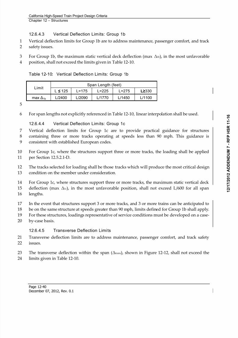
8/13/2019 California High-Speed Train Project Design Criteria
http://slidepdf.com/reader/full/california-high-speed-train-project-design-criteria 48/116
California High-Speed Train Project Design Criteria
Chapter 12 – Structures
Page 12-40December 07, 2012, Rev. 0.1
12.6.4.3 Vertical Deflection Limits: Group 1b
Vertical deflection limits for Group 1b are to address maintenance, passenger comfort, and track1
safety issues.2
For Group 1b, the maximum static vertical deck deflection (max 1b), in the most unfavorable3
position, shall not exceed the limits given in Table 12-10.4
Table 12-10: Vertical Deflection Limits: Group 1b
LimitSpan Length (feet)
L 125 L=175 L=225 L=275 330
max 1b L/2400 L/2090 L/1770 L/1450 L/1100
5
For span lengths not explicitly referenced in Table 12-10, linear interpolation shall be used.6
12.6.4.4 Vertical Deflection Limits: Group 1c
Vertical deflection limits for Group 1c are to provide practical guidance for structures7
containing three or more tracks operating at speeds less than 90 mph. This guidance is8
consistent with established European codes.9
For Group 1c, where the structures support three or more tracks, the loading shall be applied10
per Section 12.5.2.1-D.11
The tracks selected for loading shall be those tracks which will produce the most critical design12
condition on the member under consideration.13
For Group 1c, where structures support three or more tracks, the maximum static vertical deck14
deflection (max 1c), in the most unfavorable position, shall not exceed L/600 for all span15
lengths.16
In the event that structures support 3 or more tracks, and 3 or more trains can be anticipated to17
be on the same structure at speeds greater than 90 mph, limits defined for Group 1b shall apply.18
For these structures, loadings representative of service conditions must be developed on a case-19
by-case basis.20
12.6.4.5 Transverse Deflection Limits
Transverse deflection limits are to address maintenance, passenger comfort, and track safety21issues.22
The transverse deflection within the span (trans), shown in Figure 12-12, shall not exceed the23
limits given in Table 12-10.24
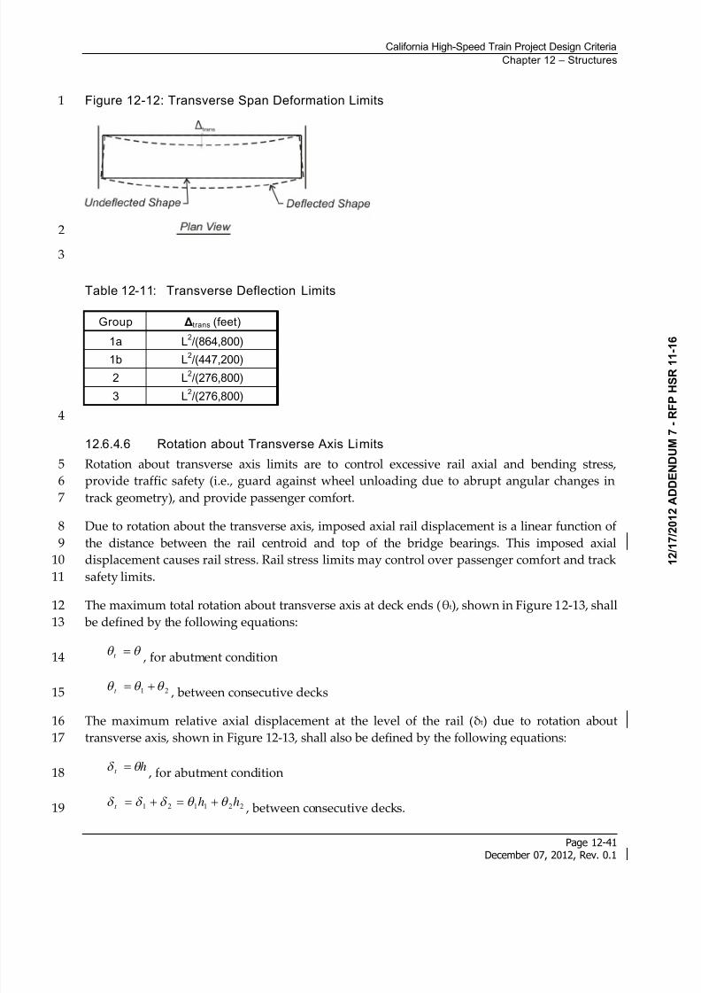
8/13/2019 California High-Speed Train Project Design Criteria
http://slidepdf.com/reader/full/california-high-speed-train-project-design-criteria 49/116
California High-Speed Train Project Design Criteria
Chapter 12 – Structures
Page 12-41December 07, 2012, Rev. 0.1
Figure 12-12: Transverse Span Deformation Limits1
2
3
Table 12-11: Transverse Deflection Limits
Group trans (feet)
1a L2/(864,800)
1b L2/(447,200)
2 L2/(276,800)
3 L2/(276,800)
4
12.6.4.6 Rotation about Transverse Axis Limits
Rotation about transverse axis limits are to control excessive rail axial and bending stress,5
provide traffic safety (i.e., guard against wheel unloading due to abrupt angular changes in6
track geometry), and provide passenger comfort.7
Due to rotation about the transverse axis, imposed axial rail displacement is a linear function of8the distance between the rail centroid and top of the bridge bearings. This imposed axial9
displacement causes rail stress. Rail stress limits may control over passenger comfort and track10
safety limits.11
The maximum total rotation about transverse axis at deck ends (t), shown in Figure 12-13, shall12
be defined by the following equations:13
t , for abutment condition14
21 t
, between consecutive decks15
The maximum relative axial displacement at the level of the rail (t) due to rotation about16
transverse axis, shown in Figure 12-13, shall also be defined by the following equations:17
ht , for abutment condition18
221121 hht , between consecutive decks.19
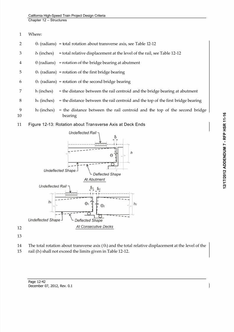
8/13/2019 California High-Speed Train Project Design Criteria
http://slidepdf.com/reader/full/california-high-speed-train-project-design-criteria 50/116
California High-Speed Train Project Design Criteria
Chapter 12 – Structures
Page 12-42December 07, 2012, Rev. 0.1
Where:1
t (radians) = total rotation about transverse axis, see Table 12-122
t (inches) = total relative displacement at the level of the rail, see Table 12-123
(radians) = rotation of the bridge bearing at abutment4
1 (radians) = rotation of the first bridge bearing5
2 (radians) = rotation of the second bridge bearing6
h (inches) = the distance between the rail centroid and the bridge bearing at abutment7
h1 (inches) = the distance between the rail centroid and the top of the first bridge bearing8
h2 (inches) = the distance between the rail centroid and the top of the second bridge9
bearing10
Figure 12-13: Rotation about Transverse Axis at Deck Ends11
12
13
The total rotation about transverse axis (t) and the total relative displacement at the level of the14
rail (t) shall not exceed the limits given in Table 12-12.15
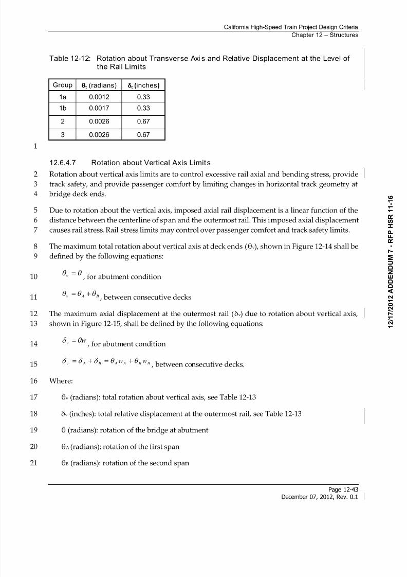
8/13/2019 California High-Speed Train Project Design Criteria
http://slidepdf.com/reader/full/california-high-speed-train-project-design-criteria 51/116
California High-Speed Train Project Design Criteria
Chapter 12 – Structures
Page 12-43December 07, 2012, Rev. 0.1
Table 12-12: Rotation about Transverse Axis and Relative Displacement at the Level ofthe Rail Limi ts
Group t (radians) t (inches)
1a 0.0012 0.33
1b 0.0017 0.33
2 0.0026 0.67
3 0.0026 0.67
1
12.6.4.7 Rotation about Vertical Axis Limits
Rotation about vertical axis limits are to control excessive rail axial and bending stress, provide2
track safety, and provide passenger comfort by limiting changes in horizontal track geometry at3
bridge deck ends.4
Due to rotation about the vertical axis, imposed axial rail displacement is a linear function of the5
distance between the centerline of span and the outermost rail. This imposed axial displacement6
causes rail stress. Rail stress limits may control over passenger comfort and track safety limits.7
The maximum total rotation about vertical axis at deck ends (v), shown in Figure 12-14 shall be8
defined by the following equations:9
v , for abutment condition10
B Av , between consecutive decks11
The maximum axial displacement at the outermost rail (v) due to rotation about vertical axis,12
shown in Figure 12-15, shall be defined by the following equations:13
wv , for abutment condition14
B B A A B Av ww , between consecutive decks.15
Where:16
v (radians): total rotation about vertical axis, see Table 12-1317
v (inches): total relative displacement at the outermost rail, see Table 12-1318
(radians): rotation of the bridge at abutment19
A (radians): rotation of the first span20
B (radians): rotation of the second span21
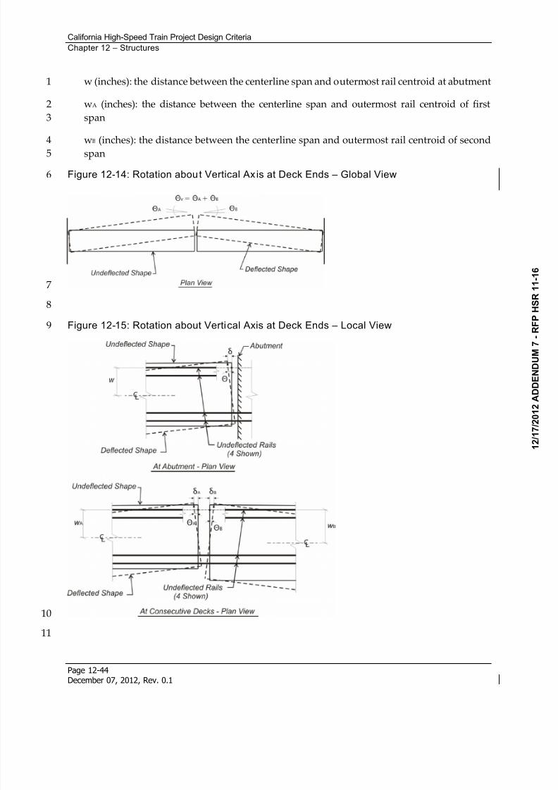
8/13/2019 California High-Speed Train Project Design Criteria
http://slidepdf.com/reader/full/california-high-speed-train-project-design-criteria 52/116
California High-Speed Train Project Design Criteria
Chapter 12 – Structures
Page 12-44December 07, 2012, Rev. 0.1
w (inches): the distance between the centerline span and outermost rail centroid at abutment1
wA (inches): the distance between the centerline span and outermost rail centroid of first2
span3
wB (inches): the distance between the centerline span and outermost rail centroid of second4span5
Figure 12-14: Rotation about Vertical Ax is at Deck Ends – Global View6
7
8
Figure 12-15: Rotation about Vertical Axis at Deck Ends – Local View9
10
11
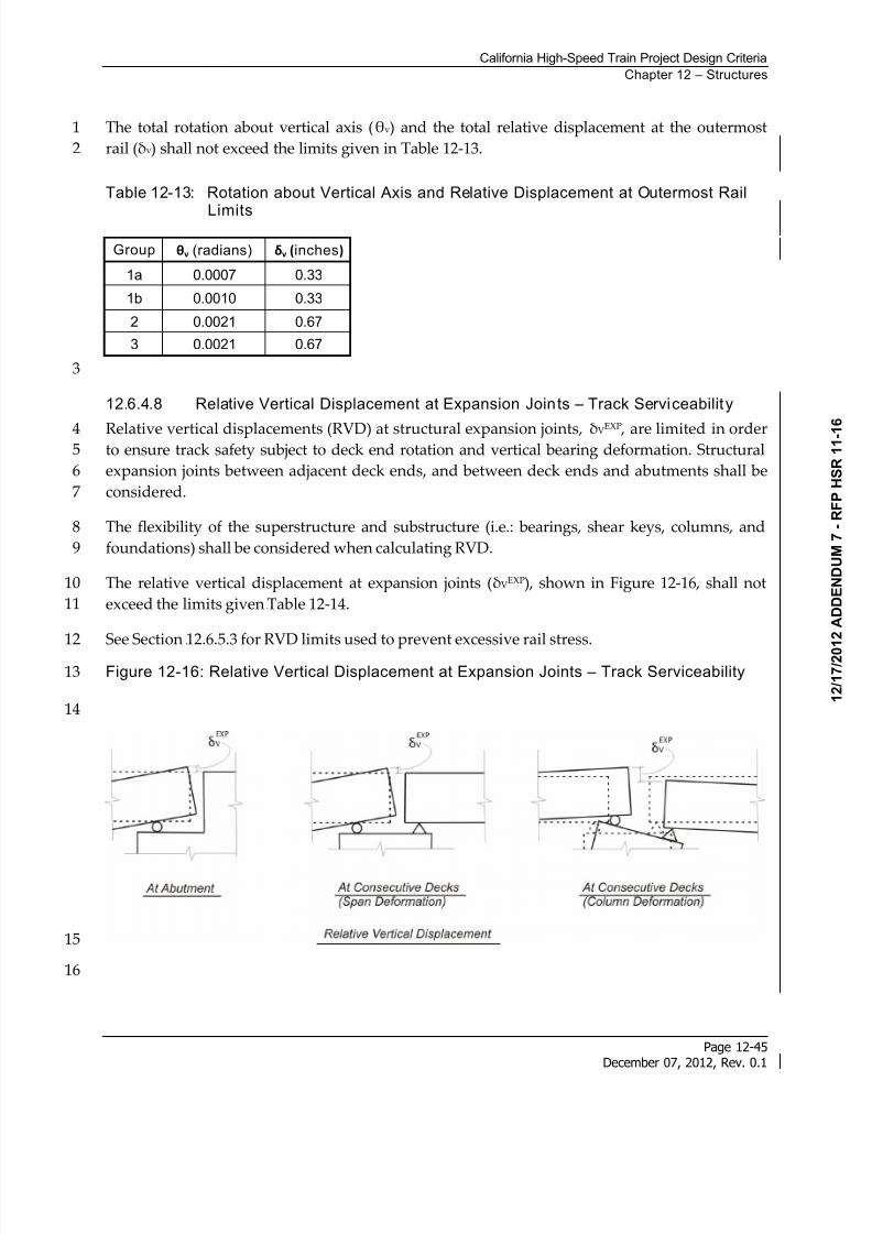
8/13/2019 California High-Speed Train Project Design Criteria
http://slidepdf.com/reader/full/california-high-speed-train-project-design-criteria 53/116
California High-Speed Train Project Design Criteria
Chapter 12 – Structures
Page 12-45December 07, 2012, Rev. 0.1
The total rotation about vertical axis (v) and the total relative displacement at the outermost1
rail (v) shall not exceed the limits given in Table 12-13.2
Table 12-13: Rotation about Vertical Axis and Relative Displacement at Outermost Rail
Limits
Group v (radians) v (inches)
1a 0.0007 0.33
1b 0.0010 0.33
2 0.0021 0.67
3 0.0021 0.67
3
12.6.4.8 Relative Vertical Displacement at Expansion Joints – Track Serviceability
Relative vertical displacements (RVD) at structural expansion joints, VEXP
, are limited in order4to ensure track safety subject to deck end rotation and vertical bearing deformation. Structural5
expansion joints between adjacent deck ends, and between deck ends and abutments shall be6
considered.7
The flexibility of the superstructure and substructure (i.e.: bearings, shear keys, columns, and8
foundations) shall be considered when calculating RVD.9
The relative vertical displacement at expansion joints (VEXP), shown in Figure 12-16, shall not10
exceed the limits given 189HTable 12-14.11
See Section 190H12.6.5.3 for RVD limits used to prevent excessive rail stress.12
Figure 12-16: Relative Vertical Displacement at Expansion Joints – Track Serviceability13
14
15
16
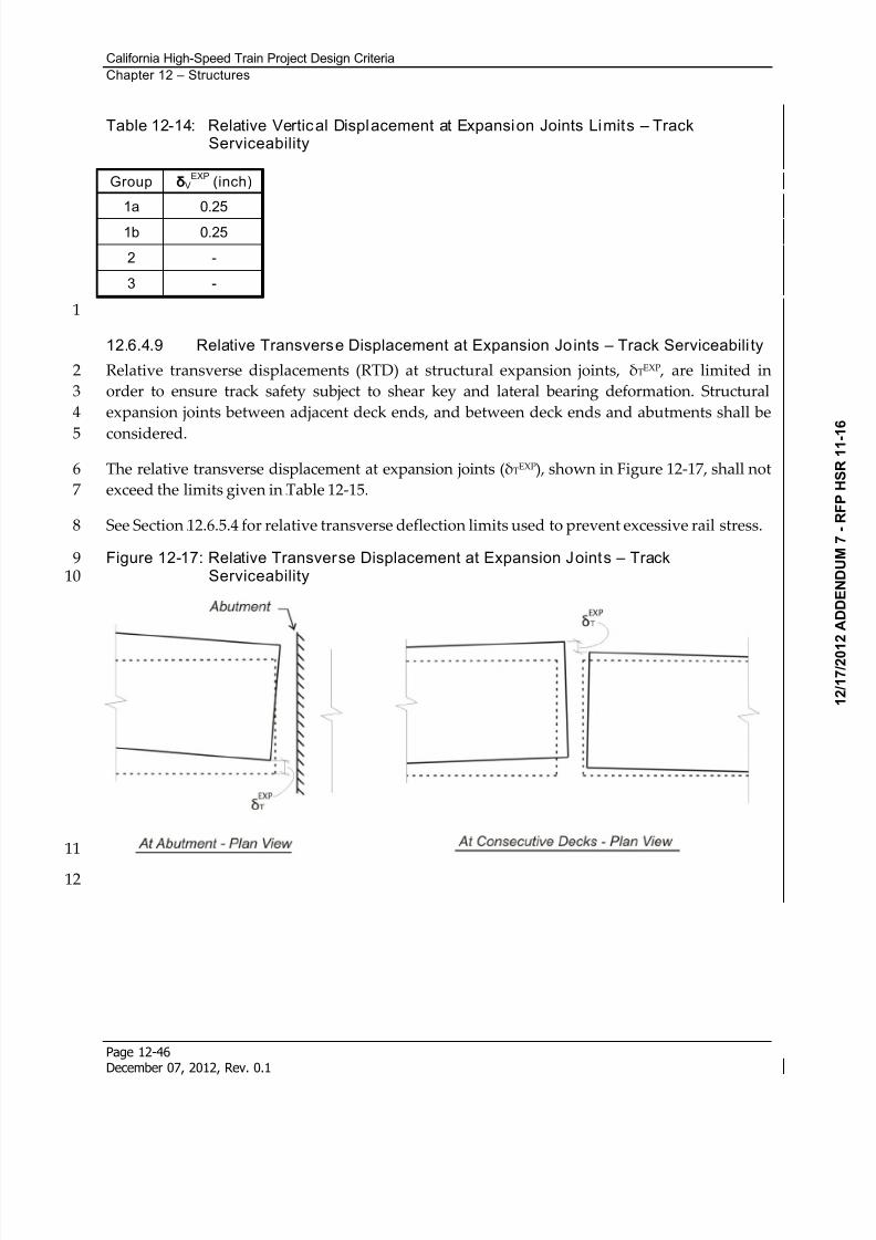
8/13/2019 California High-Speed Train Project Design Criteria
http://slidepdf.com/reader/full/california-high-speed-train-project-design-criteria 54/116
California High-Speed Train Project Design Criteria
Chapter 12 – Structures
Page 12-46December 07, 2012, Rev. 0.1
Table 12-14: Relative Vertical Displacement at Expansion Joints Limits – TrackServiceability
Group VEXP
(inch)
1a 0.25
1b 0.25
2 -
3 -
1
12.6.4.9 Relative Transverse Displacement at Expansion Joints – Track Serviceabili ty
Relative transverse displacements (RTD) at structural expansion joints, TEXP , are limited in2
order to ensure track safety subject to shear key and lateral bearing deformation. Structural3
expansion joints between adjacent deck ends, and between deck ends and abutments shall be4
considered.5
The relative transverse displacement at expansion joints (TEXP), shown in Figure 12-17, shall not6
exceed the limits given in 191HTable 12-15.7
See Section 192H12.6.5.4 for relative transverse deflection limits used to prevent excessive rail stress.8
Figure 12-17: Relative Transverse Displacement at Expansion Joints – Track9Serviceability10
11
12
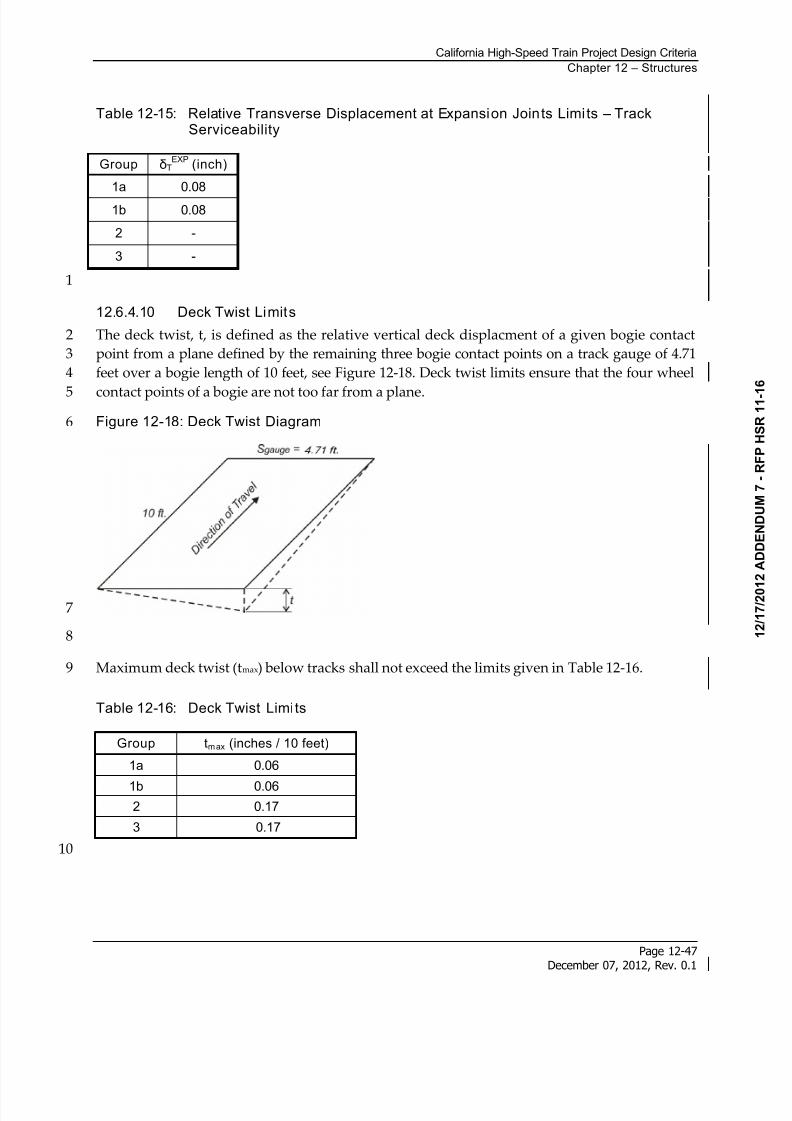
8/13/2019 California High-Speed Train Project Design Criteria
http://slidepdf.com/reader/full/california-high-speed-train-project-design-criteria 55/116
California High-Speed Train Project Design Criteria
Chapter 12 – Structures
Page 12-47December 07, 2012, Rev. 0.1
Table 12-15: Relative Transverse Displacement at Expansion Joints Limits – TrackServiceability
Group TEXP
(inch)
1a 0.08
1b 0.08
2 -
3 -
1
12.6.4.10 Deck Twist Limits
The deck twist, t, is defined as the relative vertical deck displacment of a given bogie contact2
point from a plane defined by the remaining three bogie contact points on a track gauge of 4.713
feet over a bogie length of 10 feet, see Figure 12-18. Deck twist limits ensure that the four wheel4
contact points of a bogie are not too far from a plane.5
Figure 12-18: Deck Twist Diagram6
7
8
Maximum deck twist (tmax) below tracks shall not exceed the limits given in Table 12-16.9
Table 12-16: Deck Twist Limits
Group tmax (inches / 10 feet)
1a 0.06
1b 0.06
2 0.17
3 0.17
10
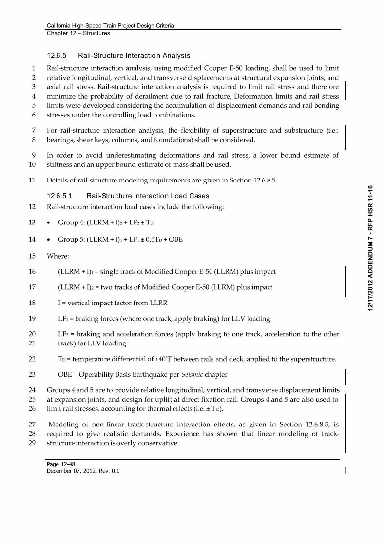
8/13/2019 California High-Speed Train Project Design Criteria
http://slidepdf.com/reader/full/california-high-speed-train-project-design-criteria 56/116
California High-Speed Train Project Design Criteria
Chapter 12 – Structures
Page 12-48December 07, 2012, Rev. 0.1
12.6.5 Rail-Structure Interaction Analysis
Rail-structure interaction analysis, using modified Cooper E-50 loading, shall be used to limit1
relative longitudinal, vertical, and transverse displacements at structural expansion joints, and2
axial rail stress. Rail-structure interaction analysis is required to limit rail stress and therefore3
minimize the probability of derailment due to rail fracture, Deformation limits and rail stress4limits were developed considering the accumulation of displacement demands and rail bending5
stresses under the controlling load combinations.6
For rail-structure interaction analysis, the flexibility of superstructure and substructure (i.e.:7
bearings, shear keys, columns, and foundations) shall be considered.8
In order to avoid underestimating deformations and rail stress, a lower bound estimate of9
stiffness and an upper bound estimate of mass shall be used.10
Details of rail-structure modeling requirements are given in Section 12.6.8.5.11
12.6.5.1 Rail-Structure Interaction Load Cases
Rail-structure interaction load cases include the following:12
Group 4: (LLRM + I)2 + LF2 ± TD 13
Group 5: (LLRM + I)1 + LF1 ± 0.5TD + OBE14
Where:15
(LLRM + I)1 = single track of Modified Cooper E-50 (LLRM) plus impact16
(LLRM + I)2 = two tracks of Modified Cooper E-50 (LLRM) plus impact17
I = vertical impact factor from LLRR18
LF1 = braking forces (where one track, apply braking) for LLV loading19
LF2 = braking and acceleration forces (apply braking to one track, acceleration to the other20
track) for LLV loading21
TD = temperature differential of ±40F between rails and deck, applied to the superstructure.22
OBE = Operability Basis Earthquake per Seismic chapter23
Groups 4 and 5 are to provide relative longitudinal, vertical, and transverse displacement limits24
at expansion joints, and design for uplift at direct fixation rail. Groups 4 and 5 are also used to25
limit rail stresses, accounting for thermal effects (i.e. ± TD).26
Modeling of non-linear track-structure interaction effects, as given in Section 12.6.8.5, is27
required to give realistic demands. Experience has shown that linear modeling of track-28
structure interaction is overly conservative.29
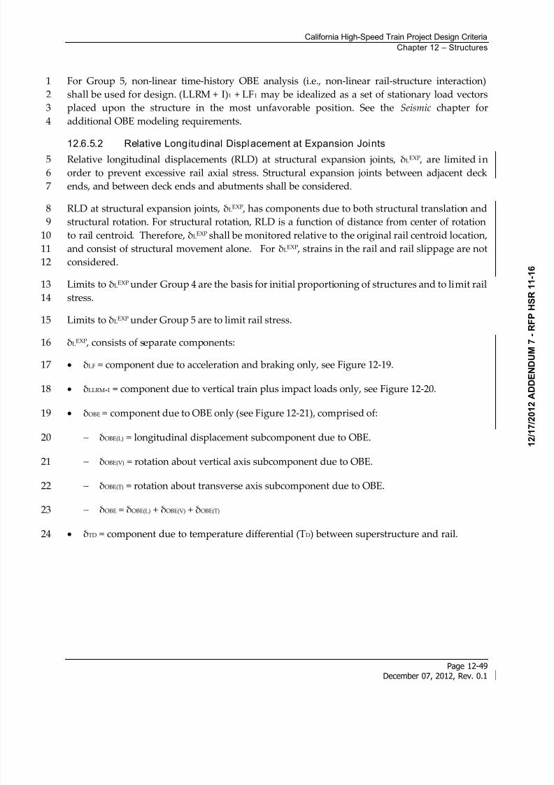
8/13/2019 California High-Speed Train Project Design Criteria
http://slidepdf.com/reader/full/california-high-speed-train-project-design-criteria 57/116
California High-Speed Train Project Design Criteria
Chapter 12 – Structures
Page 12-49December 07, 2012, Rev. 0.1
For Group 5, non-linear time-history OBE analysis (i.e., non-linear rail-structure interaction)1
shall be used for design. (LLRM + I)1 + LF1 may be idealized as a set of stationary load vectors2
placed upon the structure in the most unfavorable position. See the Seismic chapter for3
additional OBE modeling requirements.4
12.6.5.2 Relative Longitudinal Displacement at Expansion Joints
Relative longitudinal displacements (RLD) at structural expansion joints, LEXP , are limited in5
order to prevent excessive rail axial stress. Structural expansion joints between adjacent deck6
ends, and between deck ends and abutments shall be considered.7
RLD at structural expansion joints, LEXP , has components due to both structural translation and8
structural rotation. For structural rotation, RLD is a function of distance from center of rotation9
to rail centroid. Therefore, LEXP shall be monitored relative to the original rail centroid location,10
and consist of structural movement alone. For LEXP , strains in the rail and rail slippage are not11
considered.12
Limits to LEXP under Group 4 are the basis for initial proportioning of structures and to limit rail13
stress.14
Limits to LEXP under Group 5 are to limit rail stress.15
LEXP , consists of separate components:16
LF = component due to acceleration and braking only, see Figure 12-19.17
LLRM+I = component due to vertical train plus impact loads only, see Figure 12-20.18
OBE = component due to OBE only (see Figure 12-21), comprised of:19
OBE(L) = longitudinal displacement subcomponent due to OBE.20
OBE(V) = rotation about vertical axis subcomponent due to OBE.21
OBE(T) = rotation about transverse axis subcomponent due to OBE.22
OBE = OBE(L) + OBE(V) + OBE(T) 23
TD = component due to temperature differential (TD) between superstructure and rail.24
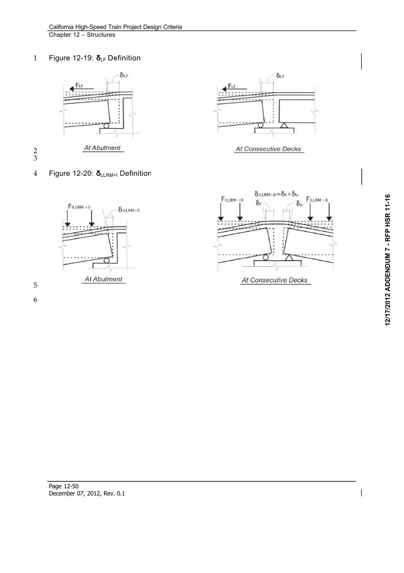
8/13/2019 California High-Speed Train Project Design Criteria
http://slidepdf.com/reader/full/california-high-speed-train-project-design-criteria 58/116
California High-Speed Train Project Design Criteria
Chapter 12 – Structures
Page 12-50December 07, 2012, Rev. 0.1
Figure 12-19: LF Definition1
23
Figure 12-20: LLRM+I Definition4
5
6
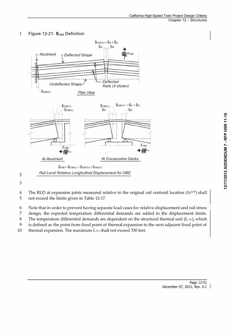
8/13/2019 California High-Speed Train Project Design Criteria
http://slidepdf.com/reader/full/california-high-speed-train-project-design-criteria 59/116
California High-Speed Train Project Design Criteria
Chapter 12 – Structures
Page 12-51December 07, 2012, Rev. 0.1
Figure 12-21: OBE Definition1
2
3
The RLD at expansion joints measured relative to the original rail centroid location (LEXP) shall4
not exceed the limits given in Table 12-17.5
Note that in order to prevent having separate load cases for relative displacement and rail stress6
design, the expected temperature differential demands are added to the displacement limits.7
The temperature differential demands are dependent on the structural thermal unit (L TU), which8
is defined as the point from fixed point of thermal expansion to the next adjacent fixed point of9
thermal expansion. The maximum LTU shall not exceed 330 feet.10
8/13/2019 California High-Speed Train Project Design Criteria
http://slidepdf.com/reader/full/california-high-speed-train-project-design-criteria 60/116
California High-Speed Train Project Design Criteria
Chapter 12 – Structures
Page 12-52December 07, 2012, Rev. 0.1
Table 12-17: Relative Longitud inal Displacement at Expansion Joints Limits
Group LEXP
(inch)
4 1.0 + TD,Expected
5 2.33 + 0.5TD,Expected
1
Where:2
TD,Expected = expected RLD measured relative to the original rail centroid location due to3
TD loading per Section 12.6.5.1. For most structures, TD,Expected can be approximated:4
TU Expected TD LT ,
5
Where:6
= coefficient of thermal expansion for the superstructure7
T = 40F temperature differential per Section 12.6.5.1. (T always positive for8
calculation of TD,Expected)9
LTU = length of structural thermal unit at a given expansion joint. If both sides of10
expansion joint are longitudinally free to displace, then both adjacent spans must be11
considered in LTU. The maximum LTU shall not exceed 330 feet. 12
For any structure which TD,Expected cannot be approximated with the above equation, including13
Complex Structures per Seismic chapter, TD,Expected shall be verified by monitoring rail-structure14
interaction models subject to TD loading per Section 193H12.6.5.1.15
12.6.5.3 Relative Vertical Displacement at Expansion Joints
Relative vertical displacement (RVD) at structural expansion joints, VEXP , are limited in order to16
prevent excessive rail bending stress.17
Structural expansion joints between adjacent deck ends, and between deck ends and abutments18
shall be considered.19
The flexibility of the superstructure and substructure (i.e.: bearings, shear keys, columns, and20
foundations) shall be considered when calculating RVD.21
The relative vertical displacement at expansion joints (VEXP), shown in Figure 12-22 shall not22
exceed the limits given in Table 12-18.23
See Section 194H12.6.4.8 for RVD limits used to promote favorable track safety, passenger comfort,24
and track maintenance.25
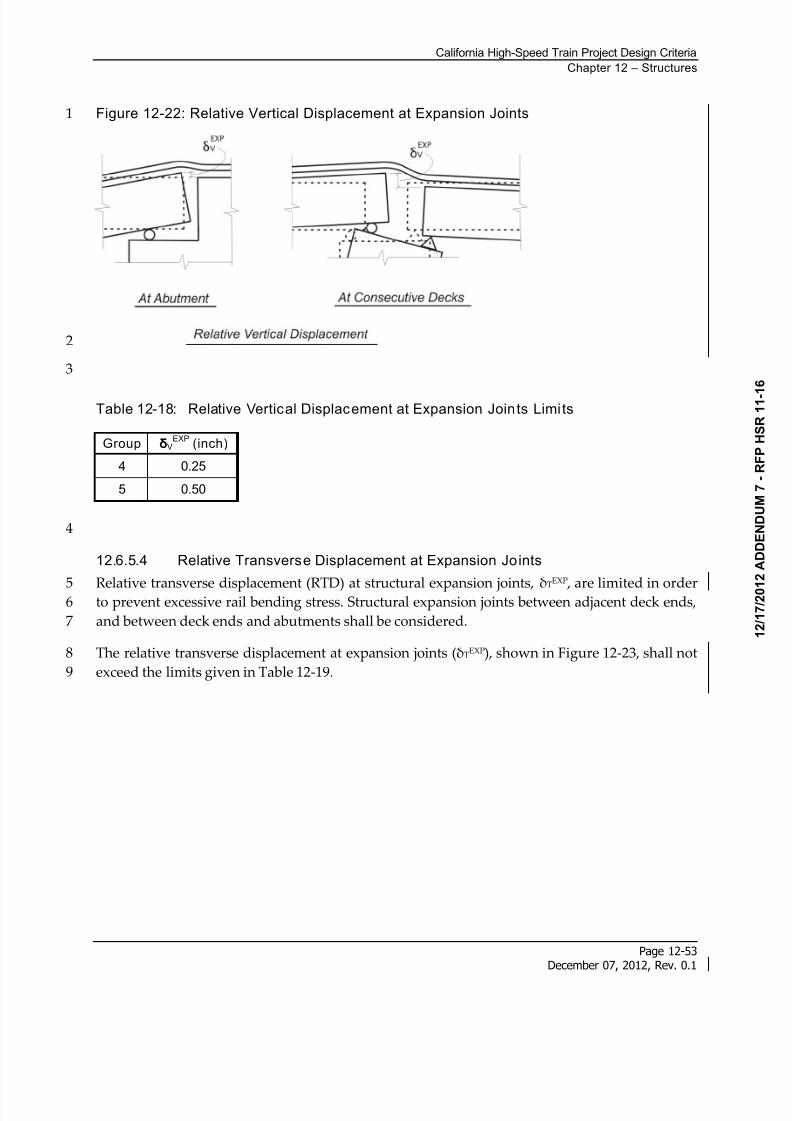
8/13/2019 California High-Speed Train Project Design Criteria
http://slidepdf.com/reader/full/california-high-speed-train-project-design-criteria 61/116
California High-Speed Train Project Design Criteria
Chapter 12 – Structures
Page 12-53December 07, 2012, Rev. 0.1
Figure 12-22: Relative Vertical Displacement at Expansion Joints1
2
3
Table 12-18: Relative Vertical Displacement at Expansion Joints Limits
Group VEXP
(inch)
4 0.25
5 0.50
4
12.6.5.4 Relative Transverse Displacement at Expansion Joints
Relative transverse displacement (RTD) at structural expansion joints, T
EXP
, are limited in order5 to prevent excessive rail bending stress. Structural expansion joints between adjacent deck ends,6
and between deck ends and abutments shall be considered.7
The relative transverse displacement at expansion joints (TEXP), shown in Figure 12-23, shall not8
exceed the limits given in Table 12-19.9
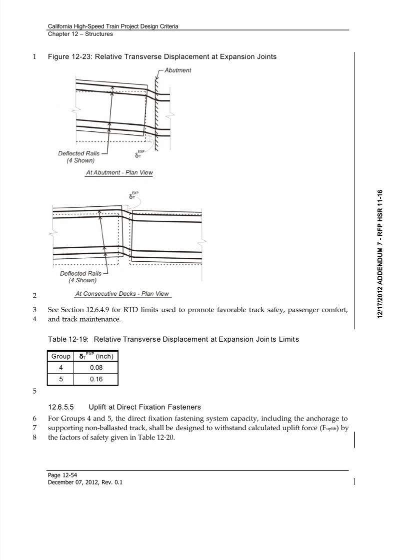
8/13/2019 California High-Speed Train Project Design Criteria
http://slidepdf.com/reader/full/california-high-speed-train-project-design-criteria 62/116
California High-Speed Train Project Design Criteria
Chapter 12 – Structures
Page 12-54December 07, 2012, Rev. 0.1
Figure 12-23: Relative Transverse Displacement at Expansion Joints1
2
See Section 195H12.6.4.9 for RTD limits used to promote favorable track safey, passenger comfort,3
and track maintenance.4
Table 12-19: Relative Transverse Displacement at Expansion Join ts Limits
Group TEXP
(inch)
4 0.08
5 0.16
5
12.6.5.5 Uplift at Direct Fixation Fasteners
For Groups 4 and 5, the direct fixation fastening system capacity, including the anchorage to6
supporting non-ballasted track, shall be designed to withstand calculated uplift force (Fuplift) by7
the factors of safety given in Table 12-20.8
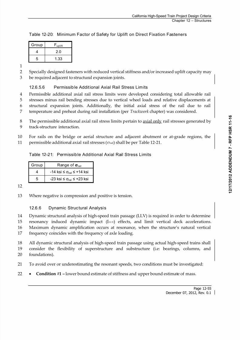
8/13/2019 California High-Speed Train Project Design Criteria
http://slidepdf.com/reader/full/california-high-speed-train-project-design-criteria 63/116
California High-Speed Train Project Design Criteria
Chapter 12 – Structures
Page 12-55December 07, 2012, Rev. 0.1
Table 12-20: Minimum Factor of Safety for Uplift on Direct Fixation Fasteners
Group Fuplift
4 2.0
5 1.33
1
Specially designed fasteners with reduced vertical stiffness and/or increased uplift capacity may2
be required adjacent to structural expansion joints.3
12.6.5.6 Permissib le Addit ional Axial Rail Stress Limits
Permissible additional axial rail stress limits were developed considering total allowable rail4
stresses minus rail bending stresses due to vertical wheel loads and relative displacements at5
structural expansion joints. Additionally, the initial axial stress of the rail due to rail6
temperature and preheat during rail installation (per Trackwork chapter) was considered.7
The permissible additional axial rail stress limits pertain to axial only rail stresses generated by8
track-structure interaction.9
For rails on the bridge or aerial structure and adjacent abutment or at-grade regions, the10
permissible additional axial rail stresses (rail) shall be per Table 12-21.11
Table 12-21: Permissib le Additional Axial Rail Stress Limits
Group Range of rail
4 -14 ksi rail +14 ksi
5 -23 ksi rail +23 ksi
12
Where negative is compression and positive is tension.13
12.6.6 Dynamic Structural Analysis
Dynamic structural analysis of high-speed train passage (LLV) is required in order to determine14
resonancy induced dynamic impact (ILLV) effects, and limit vertical deck accelerations.15
Maximum dynamic amplification occurs at resonance, when the structure’s natural vertical16
frequency coincides with the frequency of axle loading.17
All dynamic structural analysis of high-speed train passage using actual high-speed trains shall18
consider the flexibility of superstructure and substructure (i.e: bearings, columns, and19
foundations).20
To avoid over or underestimating the resonant speeds, two conditions must be investigated:21
Condition #1 – lower bound estimate of stiffness and upper bound estimate of mass.22
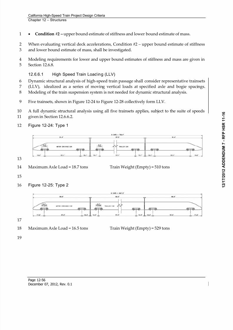
8/13/2019 California High-Speed Train Project Design Criteria
http://slidepdf.com/reader/full/california-high-speed-train-project-design-criteria 64/116
California High-Speed Train Project Design Criteria
Chapter 12 – Structures
Page 12-56December 07, 2012, Rev. 0.1
Condition #2 – upper bound estimate of stiffness and lower bound estimate of mass.1
When evaluating vertical deck accelerations, Condition #2 – upper bound estimate of stiffness2
and lower bound estimate of mass, shall be investigated.3
Modeling requirements for lower and upper bound estimates of stiffness and mass are given in4
Section 12.6.8.5
12.6.6.1 High Speed Train Loading (LLV)
Dynamic structural analysis of high-speed train passage shall consider representative trainsets6
(LLV), idealized as a series of moving vertical loads at specified axle and bogie spacings.7
Modeling of the train suspension system is not needed for dynamic structural analysis.8
Five trainsets, shown in Figure 12-24 to Figure 12-28 collectively form LLV.9
A full dynamic structural analysis using all five trainsets applies, subject to the suite of speeds10
given in Section 12.6.6.2.11
Figure 12-24: Type 112
13
Maximum Axle Load = 18.7 tons Train Weight (Empty) = 510 tons14
15
Figure 12-25: Type 216
17
Maximum Axle Load = 16.5 tons Train Weight (Empty) = 529 tons18
19
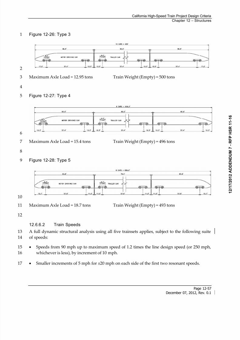
8/13/2019 California High-Speed Train Project Design Criteria
http://slidepdf.com/reader/full/california-high-speed-train-project-design-criteria 65/116
California High-Speed Train Project Design Criteria
Chapter 12 – Structures
Page 12-57December 07, 2012, Rev. 0.1
Figure 12-26: Type 31
2
Maximum Axle Load = 12.95 tons Train Weight (Empty) = 500 tons3
4
Figure 12-27: Type 45
6
Maximum Axle Load = 15.4 tons Train Weight (Empty) = 496 tons7
8
Figure 12-28: Type 59
10
Maximum Axle Load = 18.7 tons Train Weight (Empty) = 493 tons11
12
12.6.6.2 Train Speeds
A full dynamic structural analysis using all five trainsets applies, subject to the following suite13
of speeds:14
Speeds from 90 mph up to maximum speed of 1.2 times the line design speed (or 250 mph,15
whichever is less), by increment of 10 mph.16
Smaller increments of 5 mph for ±20 mph on each side of the first two resonant speeds.17
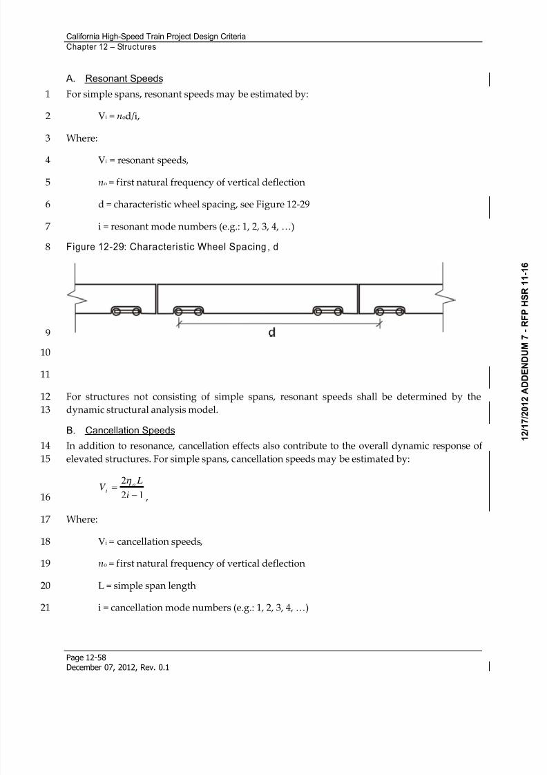
8/13/2019 California High-Speed Train Project Design Criteria
http://slidepdf.com/reader/full/california-high-speed-train-project-design-criteria 66/116
California High-Speed Train Project Design Criteria
Chapter 12 – Struct ures
Page 12-58December 07, 2012, Rev. 0.1
A. Resonant Speeds
For simple spans, resonant speeds may be estimated by:1
Vi = nod/i,2
Where:3
Vi = resonant speeds,4
no = first natural frequency of vertical deflection5
d = characteristic wheel spacing, see Figure 12-296
i = resonant mode numbers (e.g.: 1, 2, 3, 4, …)7
Figure 12-29: Characteristic Wheel Spacing , d8
9
10
11
For structures not consisting of simple spans, resonant speeds shall be determined by the12
dynamic structural analysis model.13
B. Cancellation Speeds
In addition to resonance, cancellation effects also contribute to the overall dynamic response of14
elevated structures. For simple spans, cancellation speeds may be estimated by:15
12
2
i
LV
o
i
,16
Where:17
Vi = cancellation speeds,18
no = first natural frequency of vertical deflection19
L = simple span length20
i = cancellation mode numbers (e.g.: 1, 2, 3, 4, …)21
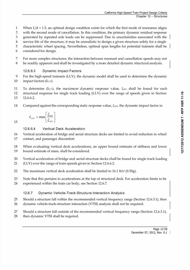
8/13/2019 California High-Speed Train Project Design Criteria
http://slidepdf.com/reader/full/california-high-speed-train-project-design-criteria 67/116
California High-Speed Train Project Design Criteria
Chapter 12 – Structures
Page 12-59December 07, 2012, Rev. 0.1
When L/d = 1.5, an optimal design condition exists for which the first mode of resonance aligns1
with the second mode of cancellation. In this condition, the primary dynamic residual response2
generated by repeated axle loads can be suppressed. Due to uncertainities associated with the3
service life of the structure, it may be unrealistic to design a given structure solely for a single4
characteristic wheel spacing. Nevertheless, optimal span lengths for potential trainsets shall be5considered for design.6
For more complex structures, the interaction between resonant and cancellation speeds may not7
be readily apparent and shall be investigated by a more detailed dynamic structural analysis.8
12.6.6.3 Dynamic Impact Factors
For the high-speed trainsets (LLV), the dynamic model shall be used to determine the dynamic9
impact factors (ILLV).10
To determine (ILLV), the maximum dynamic response value, dyn shall be found for each11
structural response for single track loading (LLV) over the range of speeds given in Section1212.6.6.2.13
Compared against the corresponding static response value, stat , the dynamic impact factor is:14
stat
dyn
LLV I
max
15
12.6.6.4 Vertical Deck Acceleration
Vertical acceleration of bridge and aerial structure decks are limited to avoid reduction in wheel16
contact, and passenger discomfort.17
When evaluating vertical deck accelerations, an upper bound estimate of stiffness and lower18
bound estimate of mass, shall be considered.19
Vertical acceleration of bridge and aerial structure decks shall be found for single track loading20
(LLV) over the range of train speeds given in Section 12.6.6.2.21
The maximum vertical deck acceleration shall be limited to 16.1 ft/s2 (0.50g).22
Note that this pertains to accelerations at the top of structural deck. For acceleration limits to be23
experienced within the train car body, see Section 12.6.7.24
12.6.7 Dynamic Vehicle-Track-Structu re Interaction Analysis
Should a structure fall within the recommended vertical frequency range (Section 12.6.3.1), then25
dynamic vehicle-track-structure interaction (VTSI) analysis shall not be required.26
Should a structure fall outside of the recommended vertical frequency range (Section 12.6.3.1),27
then dynamic VTSI shall be required.28
8/13/2019 California High-Speed Train Project Design Criteria
http://slidepdf.com/reader/full/california-high-speed-train-project-design-criteria 68/116
California High-Speed Train Project Design Criteria
Chapter 12 – Structures
Page 12-60December 07, 2012, Rev. 0.1
For Complex Structures per Seismic chapter, dynamic VTSI analysis may be required, as1
determined by the approved Seismic Design and Analysis Plan.2
For typical structures, limiting the vertical, transverse, and torsional frequencies of the span,3
span deflections, relative displacements between spans, expansion joint widths, and deck4
acceleration provides sufficient guidance for track safety and passenger comfort. However, an5advanced VTSI analysis is required for structures operating outside the known limits of6
acceptable performance, or structures with untested design concepts.7
The purpose of VTSI analysis is to verify track safety and passenger comfort by considering the8
interaction between the vehicle, track, and structure.9
Track safety depends primarily upon the contact forces between the rail and the wheel. The10
ratio of lateral to vertical forces (L/V ratio) is typically used as the primary indicator of11
derailment. In addition, the magnitudes of lateral and vertical forces imparted by the wheel to12
the rail must be controlled.13
Passenger comfort depends primarily upon the the accelerations experienced within the train14car body during travel on and off bridge or aerial structures. 15
12.6.7.1 Dynamic Train-Structure Interaction Analysis Requirements
For dynamic VTSI, both a dynamic structural model and dynamic trainset models shall be used.16
The interaction of the structure and trainset models shall be considered in either a coupled or17
iterative method.18
Details of structural modeling requirements are given in Section 12.6.8.19
Due to uncertainty of trainset selection, multiple trainset models shall be proposed for dynamic20
VTSI. Each of the dynamic trainset models shall be consistent with characteristic loading of LLV21 trainsets as defined in Section 12.6.6.1, and consider the mass, stiffness, and damping22
characteristics of the wheels, bogies, suspension, and body.23
It has been shown that vehicle response is highly sensitive to track irregularities. For dynamic24
VTSI analysis, random track irregularities shall be considered directly in the VTSI model.25
Random theoretical irregularities shall be developed for FRA Track Classes using a power26
spectral density function which may be distributed into the time domain by applying the27
spectral representation method.28
Dynamic VTSI analysis shall consider a series of speeds ranging from a minimum of 90 mph up29
to maximum speed of 1.2 times the line design speed (or 250 mph, whichever is less).30
Dynamic VTSI analysis shall consider single track (i.e., one trainset) loading only.31
For the dynamic VTSI analysis, a sufficient number of cars shall be used to produce maximum32
load effects in the longest span of the structure. In addition, a sufficient number of spans within33
a long viaduct structure shall be considered to initiate any resonance effects in the train34
suspension. 35
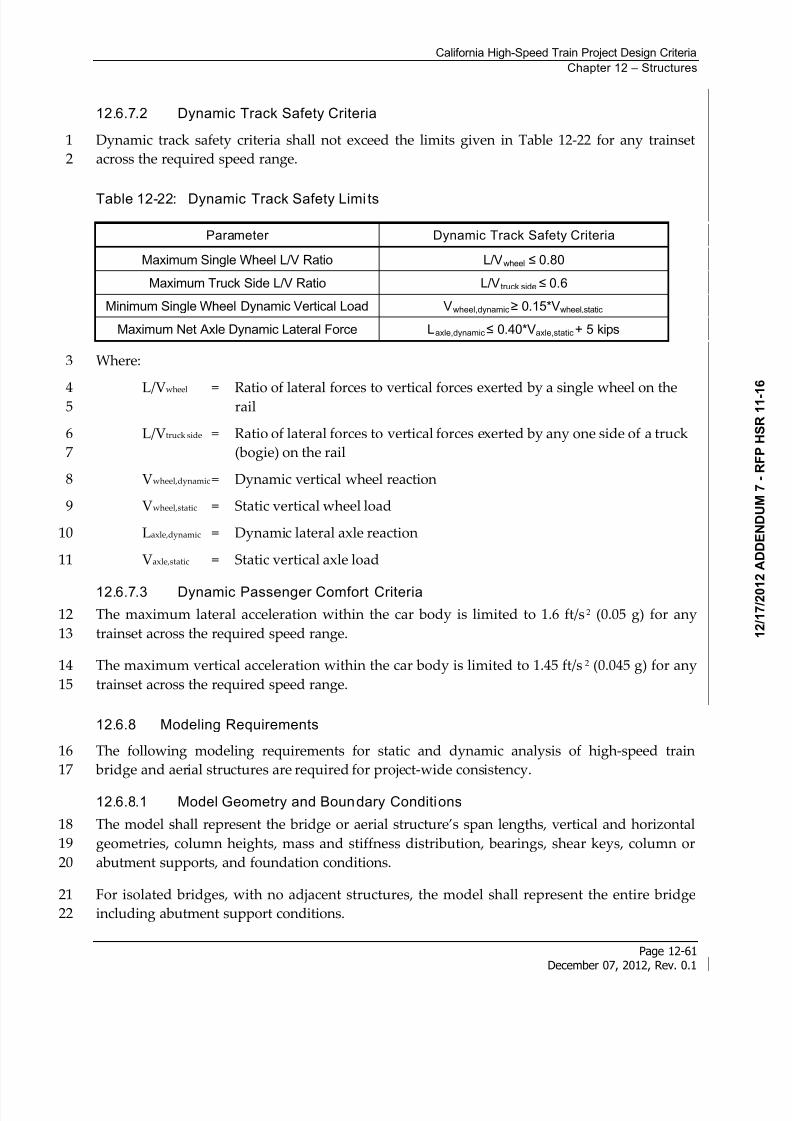
8/13/2019 California High-Speed Train Project Design Criteria
http://slidepdf.com/reader/full/california-high-speed-train-project-design-criteria 69/116
California High-Speed Train Project Design Criteria
Chapter 12 – Structures
Page 12-61December 07, 2012, Rev. 0.1
12.6.7.2 Dynamic Track Safety Criteria
Dynamic track safety criteria shall not exceed the limits given in Table 12-22 for any trainset1
across the required speed range.2
Table 12-22: Dynamic Track Safety Limi ts
Parameter Dynamic Track Safety Criteria
Maximum Single Wheel L/V Ratio L/Vwheel 0.80
Maximum Truck Side L/V Ratio L/Vtruck side 0.6
Minimum Single Wheel Dynamic Vertical Load Vwheel,dynamic 0.15*Vwheel,static
Maximum Net Axle Dynamic Lateral Force Laxle,dynamic 0.40*Vaxle,static+ 5 kips
Where: 3
L/Vwheel = Ratio of lateral forces to vertical forces exerted by a single wheel on the4rail 5
L/Vtruck side = Ratio of lateral forces to vertical forces exerted by any one side of a truck6
(bogie) on the rail 7
Vwheel,dynamic = Dynamic vertical wheel reaction8
Vwheel,static = Static vertical wheel load9
Laxle,dynamic = Dynamic lateral axle reaction10
Vaxle,static = Static vertical axle load11
12.6.7.3 Dynamic Passenger Comfort Criteria
The maximum lateral acceleration within the car body is limited to 1.6 ft/s2 (0.05 g) for any12
trainset across the required speed range.13
The maximum vertical acceleration within the car body is limited to 1.45 ft/s 2 (0.045 g) for any14
trainset across the required speed range.15
12.6.8 Modeling Requirements
The following modeling requirements for static and dynamic analysis of high-speed train16
bridge and aerial structures are required for project-wide consistency.17
12.6.8.1 Model Geometry and Boundary Conditions
The model shall represent the bridge or aerial structure’s span lengths, vertical and horizontal18
geometries, column heights, mass and stiffness distribution, bearings, shear keys, column or19
abutment supports, and foundation conditions.20
For isolated bridges, with no adjacent structures, the model shall represent the entire bridge21
including abutment support conditions.22
8/13/2019 California High-Speed Train Project Design Criteria
http://slidepdf.com/reader/full/california-high-speed-train-project-design-criteria 70/116
California High-Speed Train Project Design Criteria
Chapter 12 – Structures
Page 12-62December 07, 2012, Rev. 0.1
For repetitive aerial structure viaducts with simply supported spans the model shall have a1
minimum of 20 spans. Boundary conditions at the ends of the model shall represent the stiffness2
of any adjacent spans or frames.3
For repetitive aerial structure viaducts with continuous span frames (i.e., each frame consists of4
multiple spans with moment transfer between the deck and columns), the model shall have a5
minimum of 5 frames. Boundary conditions at the ends of the model shall represent the stiffness6
of adjacent spans or frames.7
Soil springs at the foundations shall be developed based on reports defined in the Geotechnical 8
chapter.9
For modeling of earthern embankments or cuts at bridge approaches, see Section 12.6.8.7.10
12.6.8.2 Model Stiffness
Structural elements shall be represented by the appropriate sectional properties and material11
properties.12
For frequency analysis and dynamic structural analysis, and dynamic VTSI analysis, both upper13
and lower bound estimates of stiffness shall be considered.14
For track serviceability and rail structure interaction analysis, a lower bound estimate of15
stiffness shall be considered.16
For steel superstructure and column members:17
Upper bound stiffness: full steel cross sectional properties, and expected material properties18
(larger than nominal specified per CBDS) shall be used.19
Lower bound stiffness: reduced steel cross sectional properties considering shear lag effects20
if necessary, and nominal material properties shall be used.21
For reinforced, pre-stressed, and post-tensioned concrete superstructure members:22
Upper bound stiffness: full gross bending inertia, Ig , and modulus of elasticity23
corresponding to expected material properties (1.3x nominal) per CSDC shall be used.24
Consideration shall be made for composite action of the superstructure with non-ballasted25
track, barriers or derailment walls when determining upper bound bending inertias.26
Lower bound stiffness: effective bending inertia, Ieff , per CSDC, and modulus of elasticity27
corresponding to nominal material properties shall be used.28
For concrete column members:29
Upper bound stiffness: full gross bending inertia, Ig , and modulus of elasticity30
corresponding to expected material properties (1.3x nominal) per CSDC shall be used.31
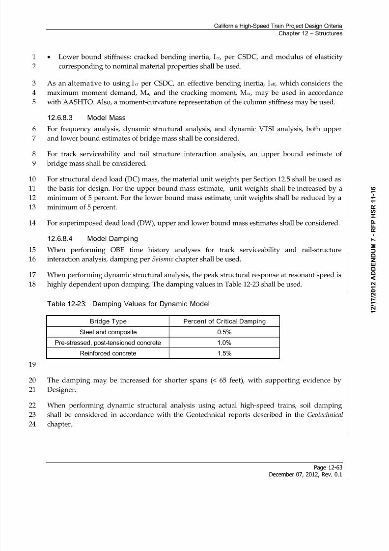
8/13/2019 California High-Speed Train Project Design Criteria
http://slidepdf.com/reader/full/california-high-speed-train-project-design-criteria 71/116
California High-Speed Train Project Design Criteria
Chapter 12 – Structures
Page 12-63December 07, 2012, Rev. 0.1
Lower bound stiffness: cracked bending inertia, Icr , per CSDC, and modulus of elasticity1
corresponding to nominal material properties shall be used.2
As an alternative to using Icr per CSDC, an effective bending inertia, Ieff , which considers the3
maximum moment demand, Ma
, and the cracking moment, Mcr
, may be used in accordance4 with AASHTO. Also, a moment-curvature representation of the column stiffness may be used.5
12.6.8.3 Model Mass
For frequency analysis, dynamic structural analysis, and dynamic VTSI analysis, both upper6
and lower bound estimates of bridge mass shall be considered.7
For track serviceability and rail structure interaction analysis, an upper bound estimate of8
bridge mass shall be considered.9
For structural dead load (DC) mass, the material unit weights per Section 12.5 shall be used as10
the basis for design. For the upper bound mass estimate, unit weights shall be increased by a11
minimum of 5 percent. For the lower bound mass estimate, unit weights shall be reduced by a12
minimum of 5 percent.13
For superimposed dead load (DW), upper and lower bound mass estimates shall be considered.14
12.6.8.4 Model Damping
When performing OBE time history analyses for track serviceability and rail-structure15
interaction analysis, damping per Seismic chapter shall be used.16
When performing dynamic structural analysis, the peak structural response at resonant speed is17
highly dependent upon damping. The damping values in Table 12-23 shall be used.18
Table 12-23: Damping Values for Dynamic Model
Bridge Type Percent of Critical Damping
Steel and composite 0.5%
Pre-stressed, post-tensioned concrete 1.0%
Reinforced concrete 1.5%
19
The damping may be increased for shorter spans (< 65 feet), with supporting evidence by20
Designer.21
When performing dynamic structural analysis using actual high-speed trains, soil damping22
shall be considered in accordance with the Geotechnical reports described in the Geotechnical 23
chapter.24
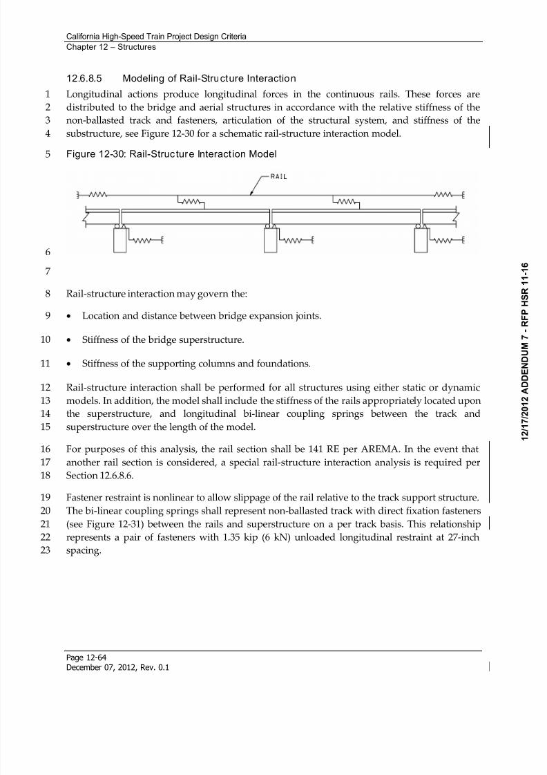
8/13/2019 California High-Speed Train Project Design Criteria
http://slidepdf.com/reader/full/california-high-speed-train-project-design-criteria 72/116
California High-Speed Train Project Design Criteria
Chapter 12 – Structures
Page 12-64December 07, 2012, Rev. 0.1
12.6.8.5 Modeling of Rail-Structure Interaction
Longitudinal actions produce longitudinal forces in the continuous rails. These forces are1
distributed to the bridge and aerial structures in accordance with the relative stiffness of the2
non-ballasted track and fasteners, articulation of the structural system, and stiffness of the3
substructure, see Figure 12-30 for a schematic rail-structure interaction model.4
Figure 12-30: Rail-Structure Interact ion Model5
6
7
Rail-structure interaction may govern the:8
Location and distance between bridge expansion joints.9
Stiffness of the bridge superstructure.10
Stiffness of the supporting columns and foundations.11
Rail-structure interaction shall be performed for all structures using either static or dynamic12
models. In addition, the model shall include the stiffness of the rails appropriately located upon13
the superstructure, and longitudinal bi-linear coupling springs between the track and14
superstructure over the length of the model.15
For purposes of this analysis, the rail section shall be 141 RE per AREMA. In the event that16
another rail section is considered, a special rail-structure interaction analysis is required per17
Section 199H12.6.8.6.18
Fastener restraint is nonlinear to allow slippage of the rail relative to the track support structure.19
The bi-linear coupling springs shall represent non-ballasted track with direct fixation fasteners20
(see Figure 12-31) between the rails and superstructure on a per track basis. This relationship21
represents a pair of fasteners with 1.35 kip (6 kN) unloaded longitudinal restraint at 27-inch22
spacing.23
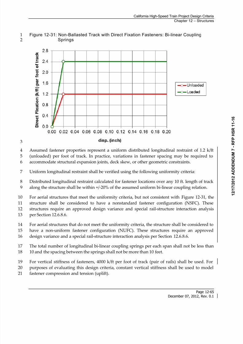
8/13/2019 California High-Speed Train Project Design Criteria
http://slidepdf.com/reader/full/california-high-speed-train-project-design-criteria 73/116
California High-Speed Train Project Design Criteria
Chapter 12 – Structures
Page 12-65December 07, 2012, Rev. 0.1
Figure 12-31: Non-Ballasted Track with Direct Fixation Fasteners: Bi-linear Coupling1Springs2
3
Assumed fastener properties represent a uniform distributed longitudinal restraint of 1.2 k/ft4
(unloaded) per foot of track. In practice, variations in fastener spacing may be required to5
accommodate structural expansion joints, deck skew, or other geometric constraints.6
Uniform longitudinal restraint shall be verified using the following uniformity criteria:7
Distributed longitudinal restraint calculated for fastener locations over any 10 ft. length of track8along the structure shall be within +/-20% of the assumed uniform bi-linear coupling relation.9
For aerial structures that meet the uniformity criteria, but not consistent with 200HFigure 12-31, the10
structure shall be considered to have a nonstandard fastener configuration (NSFC). These11
structures require an approved design variance and special rail-structure interaction analysis12
per Section 201H12.6.8.6.13
For aerial structures that do not meet the uniformity criteria, the structure shall be considered to14
have a non-uniform fastener configuration (NUFC). These structures require an approved15
design variance and a special rail-structure interaction analysis per Section 202H12.6.8.6.16
The total number of longitudinal bi-linear coupling springs per each span shall not be less than17
10 and the spacing between the springs shall not be more than 10 feet.18
For vertical stiffness of fasteners, 4000 k/ft per foot of track (pair of rails) shall be used. For19
purposes of evaluating this design criteria, constant vertical stiffness shall be used to model20
fastener compression and tension (uplift).21
8/13/2019 California High-Speed Train Project Design Criteria
http://slidepdf.com/reader/full/california-high-speed-train-project-design-criteria 74/116
California High-Speed Train Project Design Criteria
Chapter 12 – Structures
Page 12-66December 07, 2012, Rev. 0.1
For lateral (i.e., transverse) stiffness of fasteners, 450 k/ft per foot of track (pair of rails) shall be1
used.2
12.6.8.6 Special Rail-Struc ture Interaction Analysis
Rail-structure interaction limits are developed considering typical fastener configurations on3 typical structures. For those systems that do not meet these assumptions, new limits must be4
developed using a refined analysis.5
A special rail-structure interaction analysis shall be required for those structure and track6
designs requiring a design variance. Specific design variances requiring special rail-structure7
interaction analysis include, but are not necessarily limited to: designs requiring nonstandard8
fastener configurations (NSFC), non-uniform fastener configurations (NUFC), rail section other9
than RE 141, structures with thermal units (LTU) greater than 330 feet, rail expansion joints10
(REJs), and ballasted track on aerial structures.11
The Contractor shall identify and document structure types requiring special rail-structure12interaction analysis as part of the Type Selection process described in Section 12.8.1.1. After13
completion of Type Selection and upon determination that the selected structure type requires a14
special rail-structure interaction analysis, the Contractor shall develop a Rail Stress and15
Fasteners Design and Analysis Plan (RSFDAP) as part of the design variance submittal. The16
RSFDAP shall formally identify elements requiring special consideration, including but not17
limited to: refined fastener properties, detailed temperature analysis, refined18
ballast/nonballasted properties, and rail expansion joint locations. A detailed proposal of19
analysis procedures used to verify track performance (including track safety, passenger20
comfort, track maintenance, and rail stress) shall be submitted as part of the RSFDAP.21
Examples of special analysis required may include, but is not limited to: development of new22rail-structure interaction limits, development of new analytical model elements, local rail stress23
modeling, site-specific temperature analysis, analysis of impacts to track maintenance, etc.24
12.6.8.7 Modeling of Rail-Structure Interaction at Model Boundaries
Where an abutment occurs at the ends of bridges and aerial structures, the rails and coupling25
spring fastener elements shall be extended a distance of Lext from the face of the abutment. At26
the model boundary (i.e., at Lext from abutment), a horizontal boundary spring representing the27
rail/fastener system behavior shall be used. The boundary spring, which represents unloaded28
track, shall be elastic-perfectly plastic, with a elastic spring constant of k (k/ft) yielding at P b29
(kips), which represents the maximum capacity of an infinite number of elastic fasteners.30
The yielding of the boundary spring at P b is a threshold value that should be checked31
throughout the track-structure interaction analysis. If at any point during the analysis the32
boundary spring yields at force P b , Lext should be increased and the analysis should be repeated33
until elastic boundary spring behavior is verified.34
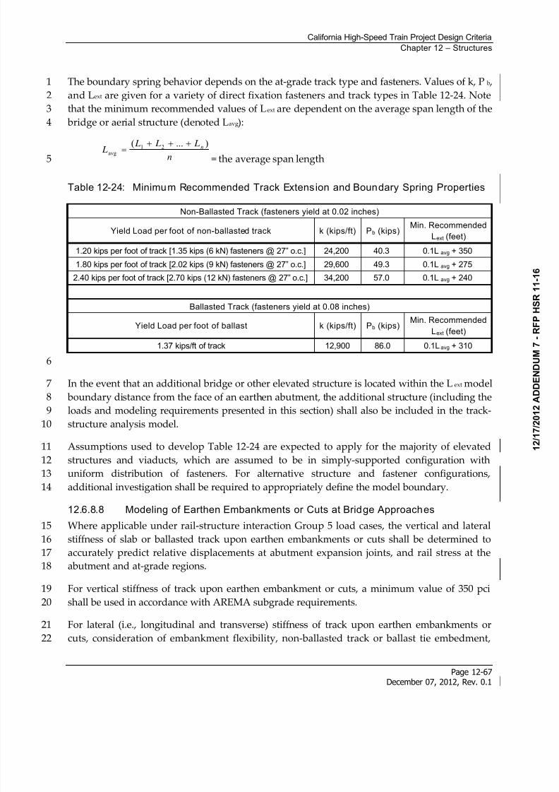
8/13/2019 California High-Speed Train Project Design Criteria
http://slidepdf.com/reader/full/california-high-speed-train-project-design-criteria 75/116
California High-Speed Train Project Design Criteria
Chapter 12 – Structures
Page 12-67December 07, 2012, Rev. 0.1
The boundary spring behavior depends on the at-grade track type and fasteners. Values of k, P b ,1
and Lext are given for a variety of direct fixation fasteners and track types in Table 12-24. Note2
that the minimum recommended values of Lext are dependent on the average span length of the3
bridge or aerial structure (denoted Lavg):4
n
L L L L n )...( 21
avg
= the average span length5
Table 12-24: Minimum Recommended Track Extension and Boundary Spring Properties
Non-Ballasted Track (fasteners yield at 0.02 inches)
Yield Load per foot of non-ballasted track k (kips/ft) Pb (kips)Min. Recommended
Lext (feet)
1.20 kips per foot of track [1.35 kips (6 kN) fasteners @ 27” o.c.] 24,200 40.3 0.1Lavg + 350
1.80 kips per foot of track [2.02 kips (9 kN) fasteners @ 27” o.c.] 29,600 49.3 0.1Lavg + 275
2.40 kips per foot of track [2.70 kips (12 kN) fasteners @ 27” o.c.] 34,200 57.0 0.1Lavg + 240
Ballasted Track (fasteners yield at 0.08 inches)
Yield Load per foot of ballast k (kips/ft) Pb (kips)Min. Recommended
Lext (feet)
1.37 kips/ft of track 12,900 86.0 0.1Lavg + 310
6
In the event that an additional bridge or other elevated structure is located within the Lext model7
boundary distance from the face of an earthen abutment, the additional structure (including the8
loads and modeling requirements presented in this section) shall also be included in the track-9 structure analysis model.10
Assumptions used to develop Table 12-24 are expected to apply for the majority of elevated11
structures and viaducts, which are assumed to be in simply-supported configuration with12
uniform distribution of fasteners. For alternative structure and fastener configurations,13
additional investigation shall be required to appropriately define the model boundary.14
12.6.8.8 Modeling of Earthen Embankments or Cuts at Bridge Approaches
Where applicable under rail-structure interaction Group 5 load cases, the vertical and lateral15
stiffness of slab or ballasted track upon earthen embankments or cuts shall be determined to16
accurately predict relative displacements at abutment expansion joints, and rail stress at the17abutment and at-grade regions.18
For vertical stiffness of track upon earthen embankment or cuts, a minimum value of 350 pci19
shall be used in accordance with AREMA subgrade requirements.20
For lateral (i.e., longitudinal and transverse) stiffness of track upon earthen embankments or21
cuts, consideration of embankment flexibility, non-ballasted track or ballast tie embedment,22
8/13/2019 California High-Speed Train Project Design Criteria
http://slidepdf.com/reader/full/california-high-speed-train-project-design-criteria 76/116
California High-Speed Train Project Design Criteria
Chapter 12 – Structures
Page 12-68December 07, 2012, Rev. 0.1
passive pressure, and friction shall be made in accordance with the Geotechnical reports1
described in the Geotechnical chapter.2
OBE ground motions shall be applied concurrently at structural foundations and earthen3
embankments or cuts to prevent incompatibility between the vibrating structure and the4
relatively stationary track upon earthen embankment or cut. For tall embankments or specific5
soil types, lag times and/or amplification effects shall be considered for OBE ground motions in6
accordance with the Geotechnical reports described in the Geotechnical chapter.7
12.7 Structural Design of Surface Facili ties and Build ings
The static design of stations, surface facilities, buildings and ancillary structures shall conform8
to the requirements of CBC, AISC, and ASCE 7 whichever is applicable except as specified9
otherwise. The seismic design of stations, surface facilities, buildings, and ancillary structures10
that are primary structures shall conform to the requirements of CBC, AISC, and ASCE 7,11
whichever is applicable. In addition, the seismic requirements of the Seismic chapter shall apply.12
For description of Primary and Secondary structures as well as seismic requirements, refer to13
the Seismic chapter.14
Primary structures supporting HSTs shall meet the requirements of Section 12.5 for Permanent15
and Transient Loads for Structures Supporting HST. If such a facility has uses other than16
supporting or in addition to HSTs or other types of bridges it shall also meet the requirements17
of this Section 12.7. For foundation design, see the requirements in the Geotechnical chapter.18
12.7.1 Load Requirements for Stations, Surface Facilit ies and BuildingsElevated and at-grade station structures not supporting HSTs, as well as surface facilities and19
buildings, shall be subject to CBC requirements, with additional criteria specific to the HST.20
Station platforms, mezzanines, and aerial pedestrian access ramps shall be subject to additional21
criteria specific to the CHSTP herein.22
12.7.1.1 Dead Load and Superimposed Dead Load
Dead load and superimposed dead load shall include but not be limited to the following:23
Dead weight of structural members and architectural finishes,24
Dead weight of road surface and of backfill above the structures,25
Dead weight of surcharge loads,26
Dead weight of equipment and appurtenances.27
Refer to Section 12.5 on Permanent and Transient Loads for Structures Supporting HST for the28
unit weights of materials.29
8/13/2019 California High-Speed Train Project Design Criteria
http://slidepdf.com/reader/full/california-high-speed-train-project-design-criteria 77/116
California High-Speed Train Project Design Criteria
Chapter 12 – Structures
Page 12-69December 07, 2012, Rev. 0.1
12.7.1.2 Train Load
Refer to Section 12.5 on Permanent and Transient Loads for Structures Supporting HST for the1
train loading.2
12.7.1.3 Roof Load
Roof live load and reduction factors shall be in accordance with the CBC.3
12.7.1.4 Floor Load
Floor live load shall be in accordance with the CBC with no reduction in floor live load, except4
for parking structures.5
Station platforms and concourse areas shall be designed for a floor live load of 100 psf.6
Emergency and maintenance walkways shall be designed for a floor live load of 100 psf.7
Floor live loads on service walkways and sidewalks shall be designed for a live load of 100 psf,8
or a concentrated load of 2,000 pounds applied anywhere on the walkway and distributed over9
a 4 feet by 2 feet area.10
The structural system supporting the access doors at street level shall be designed for a floor11
live load of 350 psf.12
Storage area floor live loads shall be 100 psf.13
Areas where cash carts are used shall be designed to accommodate a point live load of 35014
pounds per wheel. Wherever station configuration requires that cash carts cross pedestrian15
bridges, bridges shall be designed to accommodate this live load.16
Operations Control Centers shall be designed for a floor live load of 100 psf.17
Equipment room floors for such uses as signals, communications, power, transformers, battery18
storage and fanrooms shall be designed for a minimum floor loading sufficient to support both19
350 psf distributed load and a 2000 pounds concentrated load or the actual equipment weight20
located so as to produce the maximum load effects in the structural members.21
Pump rooms, service rooms, storage space, and machinery rooms shall be designed for floor22
live load of 250 psf, to be increased if storage or machinery loads so dictate.23
Stairways shall be designed for a floor live load of 100 psf or a concentrated load of 300 pounds24
on the center of stair treads, whichever is critical. Impact shall not be considered for stairways.25
Maintenance buildings will require overhead cranes and crane rails or floor mounted hydraulic26
jacks to lift individual cars from trains. The car loads are unknown until a vehicle is selected.27
The Designer shall coordinate with the Authority to obtain design requirements for crane28
design.29
8/13/2019 California High-Speed Train Project Design Criteria
http://slidepdf.com/reader/full/california-high-speed-train-project-design-criteria 78/116
California High-Speed Train Project Design Criteria
Chapter 12 – Structures
Page 12-70December 07, 2012, Rev. 0.1
12.7.1.5 Vehicular Load
Parking areas for automobiles shall be designed to a minimum load as specified in the CBC. Bus1
load shall be designed to carry HL-93 loading in accordance with AASHTO LRFD with Caltrans2
Amendments.3
Gratings in areas that are subject to vehicular loading shall be designed to carry HL-93 loading.4
12.7.1.6 Miscellaneous Loads
Pedestrian safety railings shall be designed to withstand a horizontal force of 50 pounds per5
linear foot applied at any angles to the top of the railing. The mounting of handrails and6
framing of members for railings shall be such that the completed handrail and supporting7
structure shall be capable of withstanding a load of at least 200 pounds applied in any direction8
at any point on the top rail. These loads shall not be combined with the 50 pounds per linear9
foot. For the design of structure components that support train loads and a walkway, the10
walkway live loads shall not be applied simultaneously with the train loads.11
Stationary and hinged cover assemblies internal to HST facilities shall be designed for a12
minimum uniform live load of 100 psf or a concentrated live load of 1,000 pounds over a 2 feet13
by 2 feet area. Deflection at center of span under 100 psf load shall not be more than 1/8 inch.14
Gratings in sidewalks and in areas protected from vehicular traffic shall be designed for a15
uniform live load (LL) of 300 psf.16
12.7.1.7 Slipstream Effects from Passing Trains
Refer to Section 12.5.2.7 for slipstream effects from passing high-speed trains.17
Where structural elements can also be subjected to wind load, loading due to the slipstream18 effects from passing trains shall be considered to occur in combination with wind load.19
Where trains are enclosed between walls and with a ceiling and deck, the design requirements20
for tunnels shall be met (see Tunnels chapter) including the following:21
Minimum cross section area of the through trackway22
Evacuation23
Fire/Life Safety24
Medical Health Criteria25
In addition, transient air pressure analyses (as in a tunnel ventilation analysis) shall be used to26
determine the maximum transient air pressure acting on the walls and ceiling. These pressures27
shall be used for design of those elements such as uplift of ceilings or lateral pressure on walls28
and doors.29
8/13/2019 California High-Speed Train Project Design Criteria
http://slidepdf.com/reader/full/california-high-speed-train-project-design-criteria 79/116
California High-Speed Train Project Design Criteria
Chapter 12 – Structures
Page 12-71December 07, 2012, Rev. 0.1
12.7.1.8 Seismic Design for Stations and Ancil lary Facilities
Seismic design of primary and secondary structure facilities as defined in the Seismic chapter1
shall comply with the requirements of the Seismic chapter.2
12.7.1.9 Collision Loads in Stations
Columns in stations shall be classified into three groups, according to the following criteria:3
GROUP A – This group consists of columns where the clearance measured from the TCL to4
face column and relevant conditions are as follows:5
16.5 feet6
< 16.5 feet and within the station platform area provided that the platform is of massive7
construction and the platform edge is at least 1.25 feet above the level of the nearest rail.8
No collision impact forces shall be applied.9
GROUP B – GROUP B columns are those located in a row of columns which run10adjacent and parallel to the HST track and which do not meet the criteria of GROUP A.11
Columns in the row are classified as GROUP B, with the exception of the first and last12
ones. The column row shall include a column protection wall throughout its length. .13
The performance for this loading is a no collapse requirement.14
The column protection wall shall comprise a lower guide wall together with an upper15
guide beam as shown in Figure 12-32. Due to the presence of the column protection wall,16
the GROUP B columns need not withstand full face collisions, but only grazing impacts17
by trains that have already been derailed. The lower guide wall and the upper guide18
beam shall be designed to withstand collision impact loads.19
Columns and column protection walls shall be designed for one of the following20
horizontal collision impact loads, whichever produces the most adverse effect:21
Columns shall be designed to resist a 900 kip force parallel with the TCL acting together22
with a 400 kip force at 90 degrees to the TCL, both 4 feet above low rail level and 225 kip23
force at 90 degrees to the TCL, 10 feet above TOR.24
Lower guide wall shall be designed to resist a 900 kip force parallel with the TCL acting25
together with a 400 kip force at 90 degrees to the TCL, both 3.5 feet above top of low rail.26
Upper guide beam shall be designed to resist a 350 kip force at 90 degrees to the TCL,27acting 10 feet above top of low rail.28
GROUP C – Group C consists of the first and last columns in a row that do not belong to29
Group A or Group B.30
The collision loads for each group of columns, as indicated above, are as follows:31
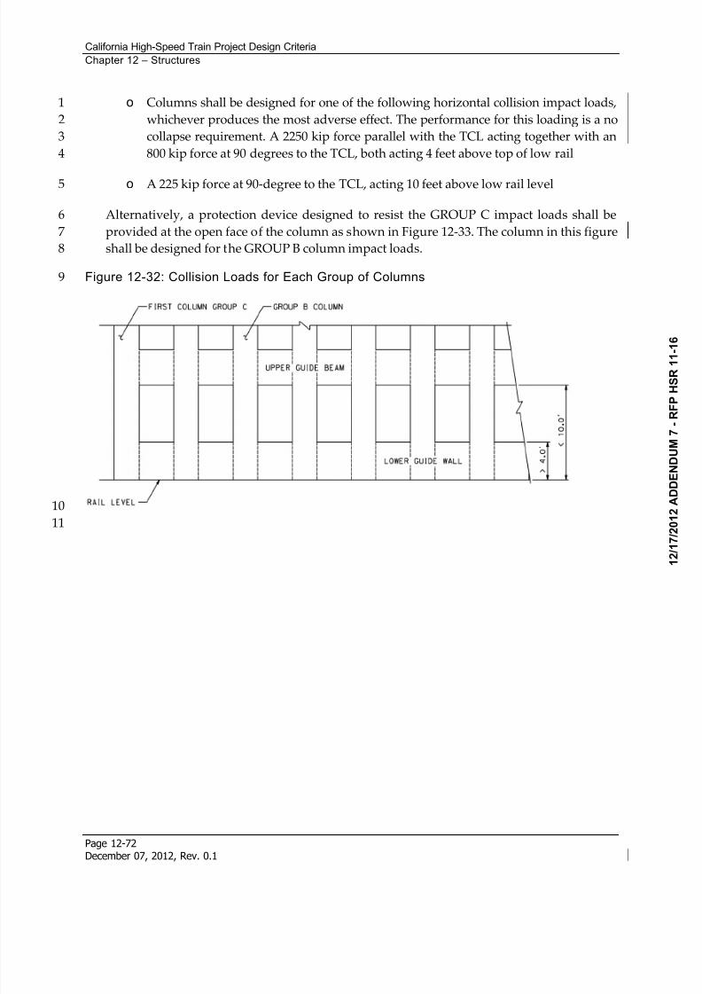
8/13/2019 California High-Speed Train Project Design Criteria
http://slidepdf.com/reader/full/california-high-speed-train-project-design-criteria 80/116
California High-Speed Train Project Design Criteria
Chapter 12 – Structures
Page 12-72December 07, 2012, Rev. 0.1
o Columns shall be designed for one of the following horizontal collision impact loads,1
whichever produces the most adverse effect. The performance for this loading is a no2
collapse requirement. A 2250 kip force parallel with the TCL acting together with an3
800 kip force at 90 degrees to the TCL, both acting 4 feet above top of low rail4
o A 225 kip force at 90-degree to the TCL, acting 10 feet above low rail level5
Alternatively, a protection device designed to resist the GROUP C impact loads shall be6
provided at the open face of the column as shown in Figure 12-33. The column in this figure7
shall be designed for the GROUP B column impact loads.8
Figure 12-32: Collision Loads for Each Group of Columns9
10
11
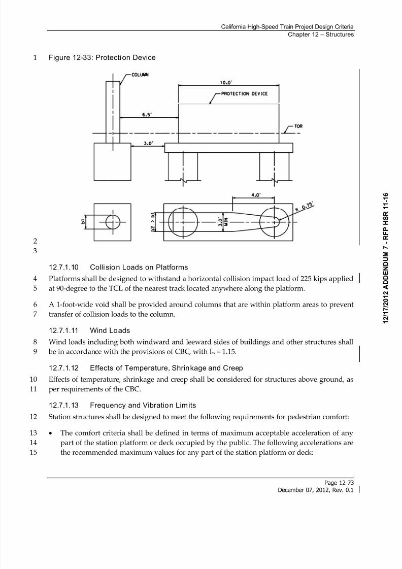
8/13/2019 California High-Speed Train Project Design Criteria
http://slidepdf.com/reader/full/california-high-speed-train-project-design-criteria 81/116
California High-Speed Train Project Design Criteria
Chapter 12 – Structures
Page 12-73December 07, 2012, Rev. 0.1
Figure 12-33: Protection Device1
2
3
12.7.1.10 Collision Loads on Platforms
Platforms shall be designed to withstand a horizontal collision impact load of 225 kips applied4
at 90-degree to the TCL of the nearest track located anywhere along the platform.5
A 1-foot-wide void shall be provided around columns that are within platform areas to prevent6
transfer of collision loads to the column.7
12.7.1.11 Wind Loads
Wind loads including both windward and leeward sides of buildings and other structures shall8
be in accordance with the provisions of CBC, with Iw = 1.15.9
12.7.1.12 Effects of Temperature, Shrinkage and Creep
Effects of temperature, shrinkage and creep shall be considered for structures above ground, as10
per requirements of the CBC.11
12.7.1.13 Frequency and Vibration Limits
Station structures shall be designed to meet the following requirements for pedestrian comfort:12
The comfort criteria shall be defined in terms of maximum acceptable acceleration of any13
part of the station platform or deck occupied by the public. The following accelerations are14
the recommended maximum values for any part of the station platform or deck:15
8/13/2019 California High-Speed Train Project Design Criteria
http://slidepdf.com/reader/full/california-high-speed-train-project-design-criteria 82/116
California High-Speed Train Project Design Criteria
Chapter 12 – Structures
Page 12-74December 07, 2012, Rev. 0.1
2.3 ft/s2 for vertical vibrations1
0.7 ft/s2 for horizontal vibrations2
1.3 ft/s2 for exceptional crowd conditions vertical vibrations3
A verification of the comfort criteria shall be performed if the fundamental frequency of the4deck is less than:5
5 Hz for vertical vibrations6
2.5 Hz for horizontal (lateral) and torsional vibrations. Transverse frequency analysis7
shall consider the flexibility of superstructure only, excluding the flexibility of bearings,8
columns, and foundations, assuming the supports at the ends of the span are rigid.9
12.7.2 Foundations for Equipment Enclosures
Refer to the Traction Power Supply System chapter, Automatic Train Control chapter, and the10
Communications chapter.11
For other equipment facilities, follow geotechnical recommendations and the provisions of CBC12
for design of foundations.13
12.7.3 Foundations for Utility Equipment
Foundations for utility equipment shall comply with the requirement of CBC and in addition14
meet the requirements of the individual utility.15
12.8 Design Considerations for Bridges and Aerial Structures
Unless otherwise specified, aerial structure design of HST structures as well as highway bridge16
structures shall be performed in accordance with AASHTO LRFD with Caltrans Amendments.17
Design of HST aerial structures shall satisfy criteria that exceed those of highway and normal18
rail bridges because of the following:19
Particular effects which are critical in HST aerial structures:20
Frequency of repetition (fatigue of materials)21
Repetitive load applications (dynamic structural response)22
Interaction of track and structure23
Riding comfort criteria24
High operating demands (life time of structure)25
8/13/2019 California High-Speed Train Project Design Criteria
http://slidepdf.com/reader/full/california-high-speed-train-project-design-criteria 83/116
California High-Speed Train Project Design Criteria
Chapter 12 – Structures
Page 12-75December 07, 2012, Rev. 0.1
Limited hours available for inspection, maintenance and repair.1
To meet the above mentioned criteria, HST aerial structures shall be designed to conform with2
the following characteristics:3
Small deflections and good resilience to dynamic responses to ensure passenger safety and a4
very high level of comfort5
Low probability of resonance6
Conceptual simplicity and standardization for ease of construction, schematic quality7
control, fast track construction and higher maintenance reliability8
Reduction of environmental noise and vibration impact.9
12.8.1 General Design Requirements
12.8.1.1 Type Selection
The type of bridges selected for design and construction shall be selected in a type selection10
process. This process is best described in the requirements of the Caltrans OSFP Information11
and Procedures Guide. The Authority’s preference for type is prestressed concrete single box12
girders carrying two tracks for main line aerial trackways and structures. Box girders can be13
precast, precast segmental, or cast in-place, cast-in-place span by span or other similar types of14
construction. For specific locations, thru girders or thru trusses constructed by piece or15
incrementally launched may be more appropriate. The Type Selection shall include seismic16
considerations, foundation recommendations, aesthetics review, traffic maintenance (both17
highway and rail), drainage considerations and intrusion protection. Included with or in the18Type Selection Report shall be all of the following that apply to the specific bridge or aerial19
structure:20
Type Selection Memo (see Caltrans OSFP Information and Procedures Guide)21
Hydrology and Hydraulics reports22
Aesthetics Design and Review Report23
Geotechnical Engineering Design Report24
Seismic Design and Analysis Plan (Seismic chapter)25
Rail Stress and Fastener Design and Analysis Plan ( Section 12.6.8.6)26
Complex and Non-Standard Aerial Structures Load Path Report (Section 12.8.7)27
If rail expansion joints are considered the variance process should start at Type Selection.28
8/13/2019 California High-Speed Train Project Design Criteria
http://slidepdf.com/reader/full/california-high-speed-train-project-design-criteria 84/116
California High-Speed Train Project Design Criteria
Chapter 12 – Structures
Page 12-76December 07, 2012, Rev. 0.1
For isolated structures and the structures not in the main line, and highway bridges, structure1
type selection shall follow the requirements of the Caltrans OSFP Information and Procedures2
Guide. The Type Selection shall be coordinated with the Authority to determine and identify3
any constraints that may control the design that are not listed in these Design Criteria.4
12.8.1.2 Clearances
Clearances requirements are specified in Trackway Clearances chapter.5
12.8.1.3 Water Crossings
Hydraulic requirements for bridge drainage and requirements for water crossings are specified6
in the Drainage chapter.7
12.8.1.4 Deck Arrangement
The arrangement of deck features shall conform to the requirements presented in the Standard8
and Directive Drawings.9
12.8.1.5 Material Requirements
A. Concrete Requirements
The minimum 28-days concrete compressive strength in aerial structures shall be as follows:10
For piles, shafts, and footing reinforced concrete cast-in-place structures, f'c = 4,000 psi.11
For above ground reinforced concrete cast-in-place structures, f'c = 5,000 psi.12
For cast-in-place prestressed concrete, f'c = 6,000 psi.13
For precast prestressed members, f'c = 6,000 psi.14
Lightweight concrete is not allowed in Primary Type 1 structures. It may be used in15
secondary concrete such as leveling or non-ballasted track concrete.16
For design of cast-in-place piles and shafts, the nominal concrete strength shall not be greater17
than f’c = 4,000 psi18
B. Reinforcing Steel
Reinforcing steel for concrete reinforcement including spiral reinforcement shall conform to19
ASTM A706/706M, Specification for Low-Alloy Steel Deformed and Plain Bars for Concrete20
Reinforcement.21
Plain wire for welded wire fabric shall comply with ASTM A82, Specification for Steel Wire,22
Plain, for Concrete Reinforcement.23
C. Concrete Cover
Minimum concrete cover shall conform to AASHTO LRFD with Caltrans Amendments Table24
5.12.3-1, with the following exceptions:25
8/13/2019 California High-Speed Train Project Design Criteria
http://slidepdf.com/reader/full/california-high-speed-train-project-design-criteria 85/116
California High-Speed Train Project Design Criteria
Chapter 12 – Structures
Page 12-77December 07, 2012, Rev. 0.1
Uncased drilled shafts: 6 inches1
Cased drilled shafts with temporary casing: 4 inches2
D. Prestressing Steel
Prestressing steel shall conform to the requirements of ASTM A416/A416M, or ASTM A722.3Prestressing strand or wire shall be low relaxation. Additional requirements follow:4
Only post-tensioning systems that utilize tendons fully encapsulated with grout within the5
anchorages and ducts are allowed.6
Embedded anchors for bars are permitted.7
Strand or tendon couplers are not permitted.8
Select the post-tensioning grout for use by the proper application either repair, horizontal,9
or vertical. Grout will be mixed with potable water.10
Grout11
Only pre-packaged grout mixes designed for the specific application are permitted. The12
grout shall not contain aluminum or other components which produce hydrogen,13
carbon dioxide or oxygen gas.14
Chemical testing of a fresh dry sample taken from a bag in each lot of prepackaged grout15
shall be performed to determine chloride concentrations in accordance with the16
following requirement. Total chloride ions shall be less than 0.08% measured by weight17
of cementious material according to ASTM C1152.18
Anchorages19
Ensure that anchorages develop at least 95 percent of the actual ultimate tensile strength20
of the prestressing steel when tested in an unbonded state, without exceeding the21
anticipated set.22
Design anchorages so the average concrete bearing stress is in compliance with23
AASHTO “Load and Resistance Factor Design (LRFD) Bridge Design Specifications.”24
Test and provide written certification that anchorages meet or exceed the testing25
requirements in the AASHTO “LRFD Bridge Construction Specifications”.26
Equip anchorages with a permanent grout cap vented and bolted to the anchorage.27
Provide wedge plates with centering lugs or shoulders to facilitate alignment with the28
bearing plate. Cast anchorages with grout outlets suitable for inspection from either the29
top or front of the anchorage. The grout outlet shall serve a dual function of grout outlet30
and post-grouting inspection access. The geometry of the grout outlets must facilitate31
being drilled using a 3/8-inch-diameter straight bit to facilitate endoscope inspection32
directly behind the anchor plate. Anchorages may be fabricated to facilitate both33
inspection locations or may be two separate anchorages of the same type – each34
providing singular inspection entry locations.35
8/13/2019 California High-Speed Train Project Design Criteria
http://slidepdf.com/reader/full/california-high-speed-train-project-design-criteria 86/116
California High-Speed Train Project Design Criteria
Chapter 12 – Structures
Page 12-78December 07, 2012, Rev. 0.1
Anchorages shall be protected with epoxy grout encapsulation with an elastomeric1
coating2
Ducts and Pipes3
Do not use ducts manufactured from recycled material.4
Use seamless fabrication methods to manufacture ducts.5
Ferrous metal ducts shall not be used.6
Precast segmental bridges with internal tendons shall use segmental duct couplers with7
6 degrees of alignment allowance at all segment joints.8
E. Structural Steel
Structural steel design for bridge-type structures shall meet the requirements of the AASHTO9
LRFD with Caltrans Amendments.10
Structural Steel Shapes shall conform to ASTM A6. Additional properties are as follows:11
Wide flange shapes: ASTM A99212
M-shapes, S-shapes, HP shapes: ASTM A57213
Angles, Channels: ASTM A57214
Rectangular and square hollow sections: ASTM A500 Gr B (46 ksi)15
Round hollow sections: ASTM A500 Gr B (42 ksi)16
Steel pipe: ASTM A53 Gr B (35 ksi)17
Plates, Bars: ASTM A36 (36 ksi)18
Bolts: ASTM A32519
Nuts: ASTM A56320
Washers: ASTM F43621
Welding of built up members and steel fabrications shall comply with AASHTO/AWS D 1.522
Welding of HSS sections and pipes shall comply with AWS D 1.123
Miscellaneous steel items shall be hot-dip galvanized after fabrication unless completely24
embedded in concrete and unless noted otherwise25
Splice Locations – If splicing of a structural steel member is permitted, indicate the location of26
the splice. Such locations shall be at or near a cross section of minimum stress.27
8/13/2019 California High-Speed Train Project Design Criteria
http://slidepdf.com/reader/full/california-high-speed-train-project-design-criteria 87/116
California High-Speed Train Project Design Criteria
Chapter 12 – Structures
Page 12-79December 07, 2012, Rev. 0.1
12.8.2 Design Loads and Effects
Aerial structure loads and load combinations are specified in Section 12.5. Track-Structure1
Interaction requirements and those specific load combinations are specified in Section 12.6.2
Seismic requirements are specified in the Seismic chapter.3
12.8.3 Foundations
12.8.3.1 Shallow Foundation Design
Shallow foundations such as spread footings shall be designed in accordance with AASHTO4
LRFD with Caltrans Amendments. Soil and rock engineering properties shall be based on the5
results of field investigations as presented in the Geotechnical reports described in the6
Geotechnical chapter. Use of presumptive values shall not be allowed.7
12.8.3.2 Deep Foundation Design
Design of deep foundations shall be based on project-specific information developed for the8
location(s) and foundation type planned. Soil and rock engineering properties shall be based on9
the results of field investigations as presented in the Geotechnical reports described in the10
Geotechnical chapter. Use of presumptive values shall not be allowed. Bottom clean out of drilled11
shafts constructed using the wet method shall be verified.12
Where permanent steel casing is used for structural capacity, it shall have a minimum wall13
thickness of 3/4 inch and be provided with internal shear lugs if composite action is to be relied14
upon. Additionally, the design basis of the steel section shall be reduced to account for15
corrosion over the life of the structure based on actual soil and ground water conditions. A site16
specific corrosion study shall be performed to determine the deduction of the wall thickness17
due to the corrosive characteristics. A minimum of 1/8 inch reduced wall thickness shall be18applied. Steel casing shall not be considered for structural support in extremely aggressive19
environments.20
Construction tolerance for drilled shafts shall be in accordance with AASHTO LRFD with21
Caltrans Amendments. For trackway shafts greater than 5 feet in diameter, the drilled shafts22
shall be designed assuming they are offset at the top of the shaft a minimum of 6 inches. Refer23
to the Standard Specification on Drilled Concrete Piers and Shafts.24
Geotechnical Design of mini-piles shall be in accordance with AASHTO LRFD with Caltrans25
Amendments, Section 10.9 Micropiles and FHWA-SA-97-070 (Micropile Design and26
Construction Guidelines, June 2000).27
The upper 5 feet as measured from lowest adjacent grade shall be discounted in any axial and28
lateral load analyses except where it can be shown that measures are provided to prevent future29
excavations around the pile within three diameters from the shaft or pile group exterior surface.30
For the analysis to obtain the demand forces the upper 5 feet shall be considered.31
8/13/2019 California High-Speed Train Project Design Criteria
http://slidepdf.com/reader/full/california-high-speed-train-project-design-criteria 88/116
California High-Speed Train Project Design Criteria
Chapter 12 – Structures
Page 12-80December 07, 2012, Rev. 0.1
12.8.4 Steel Structures
Steel through trusses and through girders may be used for longer spans requiring minimal1
structure depth and other steel built up sections, beams and girders may be used over railroads2
or highways. For through and semi-through type bridges the requirements of Section 12.5.2.133
shall be met for structural elements within 16 feet of the track centreline. Loadings shall be4considered as derailment loads applied in the Extreme 1 Load Combination in Table 12-4. .5
12.8.4.1 Continuous Steel Structures
For continuous girders and other statically indeterminate structures, the moments, shears, and6
thrusts produced by external loads shall be determined by elastic analysis. The effects of creep,7
shrinkage, axial deformation, restraint of attached structural elements, and foundation8
settlements shall be considered in the design.9
12.8.4.2 Fracture Critical Members
Fracture critical members shall be designed in accordance with AASHTO LFRD with Caltrans10
Amendments. A load factor of 1.50 shall apply to live load of the Fatigue load combination11
described in Table 12-4. Welding in tension zones in fracture critical members is not permitted.12
12.8.4.3 High Performance Coating
Steel Bridges shall have a high performance coating system such as polysiloxane, polyaspartic13
modified urethane, or fluoropolymer which may be applied in the field. Primer shall be14
inorganic or organic zinc as recommended by the manufacturer of finish coats. Coatings15
including primers shall comply, at a minimum with South Coast Air Quality Management16
District (SCAQMD) Rule 113.17
The Contractor shall provide services of an independent coating inspector. Independent coating18inspector shall be certified under NACE International’s Certified Inspector Program as a19
Certified Coating Inspector.20
12.8.4.4 Orthotrop ic Steel Decks
Steel orthotropic plate decks shall not be used for the HST mainline structures.21
12.8.4.5 Bearing Replacement
Reinforced jacking points shall be identified clearly on As-Built drawings.22
12.8.4.6 Inspection and Maintenance
Construction details of steel bridges shall facilitate maintenance and inspection so that23inspection and maintenance can be performed during non-revenue service. Structures over24
railroads or highways shall provide for the inspection and maintenance during limited access to25
the below deck elements. Steel box girders and box beams shall have access hatches to allow26
maintenance and inspection of the member.27
8/13/2019 California High-Speed Train Project Design Criteria
http://slidepdf.com/reader/full/california-high-speed-train-project-design-criteria 89/116
California High-Speed Train Project Design Criteria
Chapter 12 – Structures
Page 12-81December 07, 2012, Rev. 0.1
12.8.5 Concrete Structures
Aerial structures, bridges and grade separation superstructures may be constructed using cast-1
in-place concrete, precast girders either single span, span by span or segmental, as well as cast-2
in-place, segmental balanced cantilever or incrementally launched methods. Concrete through3
girders shall meet the same requirements as steel through girders.4
The CEP-FIP Model Code for Concrete Structures shall be used for determining time dependent5
effects due to creep, shrinkage and prestressing steel relaxation.6
12.8.5.1 Longitud inal Tension Stresses in Prestressed Members
AASHTO LRFD with Caltrans Amendments shall be used for allowable longitudinal tension7
stresses. Tension stresses are not allowed in pre-compressed tensile zones after all losses have8
occurred.9
12.8.5.2 Additional Requirements for Segmental Trackway Construct ion
Shear and torsion design to conform to AASHTO LRFD, Article 5.8.6, in addition to AASHTO10LRFD with Caltrans Amendments.11
Principal tensile stresses in webs to conform to AASHTO LRFD with Caltrans Amendments,12
Article 5.8.5.13
Precast segmental concrete construction with dry segment joints is not permitted. Joints in14
precast segmental bridges and viaducts shall be either cast-in-place closures or match cast15
epoxied joints.16
Hollow columns shall have a solid section minimum 5 feet above finished grade or 12 feet17
above high water level. Vertical post-tensioning is not allowed in the solid sections. An access18opening shall be provided near the top of the column. See Section 12.8.10 for sizes. Access19
openings shall be located outside of potential plastic hinge zones. Internal platforms and20
ladders shall be provided.21
Two inch diameter vent holes are required through the bottom flange of box girders near each22
end of each span.23
12.8.5.3 Crack Control
The design of prestressed concrete or reinforced concrete aerial structures shall consider the24
effect of temporary loads imposed by sequence of construction stages, forming, falsework, and25
construction equipment, as well as the stresses created by lifting or placing pre-cast members,26stress concentration (non-uniform bearing at the ends of pre-cast beams), end block design and27
detailing, methods of erection, shrinkage, and curing. Ensure that the structural design and28
detailing of pre-stressed or reinforced concrete members is adequate and meets durability29
requirements and that specifications are prepared which are compatible with the design so that30
crack widths are no greater than allowed by AASHTO LRFD with Caltrans Amendments Class31
2 exposure condition in construction stages or service. If the concrete member is continuously32
8/13/2019 California High-Speed Train Project Design Criteria
http://slidepdf.com/reader/full/california-high-speed-train-project-design-criteria 90/116
California High-Speed Train Project Design Criteria
Chapter 12 – Structures
Page 12-82December 07, 2012, Rev. 0.1
submerged in water or is a zone of intermittent wetting and drying the exposure factor used in1
AASHTO LRFD with Caltrans Amendments Article 5.7.3.4 shall be 0.25 or less.2
12.8.5.4 Maintenance and Inspection of Concrete Structures
Inspection and maintenance hatches shall be provided into each closed girder. These hatches3 may be through the girder soffits or in combination with openings between adjacent girder4
diaphragms.5
The minimum headroom inside of typical box girders shall be 6 feet. For two- or three-span6
short bridges with spans less than 90 feet, the minimum headroom inside of box girders shall be7
4 feet.8
Minimum clearance from girder ends to bearings and from abutment backwalls to bearings9
shall be 2.5 feet to allow for access.10
In-span hinges and associated expansion joints are not allowed.11
12.8.5.5 Continuous Concrete Structures
For continuous girders and other statically indeterminate structures, the moments, shears, and12
thrusts produced by external loads and prestressing shall be determined by elastic analysis. The13
effects of creep, shrinkage, axial deformation, restraint of attached structural elements, and14
foundation settlements shall be considered in the design.15
12.8.6 General Aerial Structure and Bridge Design Features
12.8.6.1 Bridge Skew
The preferred angle of crossing and bridge structure relative to the centerline of track is 90-16degrees. In cases where a 90-degree crossing cannot be constructed, the skew of the bridge shall17
be limited so that for each track the deck end is between successive rail fasteners and the18
applicable provisions of Section 12.6 Track-Structure Interaction are met. The maximum skew of19
a bridge from 90-degrees shall not exceed 30-degrees.20
12.8.6.2 Embankment Length Between Abutments
The length of embankment between abutments shall not be less than 500 feet. The length of21
embankment between an abutment and a culvert shall not be less than 100 feet. If closer spacing22
is required, then the embankment shall be specially treated such that a constant gradient of23
stiffness shall be provided between the two adjacent bridge deck stiffnesses. Refer to the24
Geotechnical chapter for specific requirements for embankment fills and abutment backfill.25
12.8.6.3 Containment Barr iers
Containment barriers as described in Section 12.5.2.13-B are required on all bridges and aerial26
structures.27
8/13/2019 California High-Speed Train Project Design Criteria
http://slidepdf.com/reader/full/california-high-speed-train-project-design-criteria 91/116
California High-Speed Train Project Design Criteria
Chapter 12 – Structures
Page 12-83December 07, 2012, Rev. 0.1
12.8.6.4 Intrusion Protect ion
Aerial structures shall be protected from errant highway vehicles as well as from derailed trains1
as described in the Rolling Stock and Vehicle Intrusion Protection chapter and as required in the2
following:3
A. Highway Traffic Intrusion
HST substructures, as required by the Rolling Stock and Vehicle Intrusion Protection chapter, shall4
be protected by an appropriate barrier as specified AASHTO LRFD with Caltrans Amendments5
Article 3.6.5.1 or designed for the force presented in AASHTO LRFD with Caltrans6
Amendments, Article 3.6.5.2.7
B. Railroad Intrusion
HST substructures located adjacent to conventional railroad shall be protected as specified in8
the Rolling Stock and Vehicle Intrusion Protection chapter. The design shall follow the9
requirements of AASHTO LRFD with Caltrans Amendments, Article 2.3.3.4. If an independent10
intrusion barrier is not provided, the substructure shall be designed to resist forces presented in11Section 12.5.2.14.12
12.8.6.5 Uplift
There shall be no net uplift at any support for any combination of loadings.13
12.8.6.6 Friction
Friction shall be considered in the design where applicable.14
12.8.6.7 Sound Barriers
Sound barriers, both presence and absence, shall be considered in the evaluation of stress,15
vibration, and deflection limits.16
12.8.6.8 Drainage
Drainage of water from aerial structures, bridges and grade separations shall be accomplished17
by sloping the deck towards the center of the deck, and sloping the girders towards a pier18
support or abutment. Water shall be collected and conveyed to a drainage pipe cast into the19
concrete substructure. The pipe shall pass through the pier columns and abutment walls to exit20
through the foundations. Column reinforcing in potential plastic hinge zones shall not be21
interrupted for drain pipes. Refer to the Drainage chapter for other requirements.22
12.8.6.9 Expansion Joints
Expansion Joints shall be provided between girder ends and between girder end and abutment23
walls to allow superstructure movements and prevent water and other material from falling24
from the superstructure. Expansion joints are not required to resist highway or rail traffic loads,25
but shall be protected from ballast if ballast is used. Expansion joints may be part of a bridge26
drainage system.27
8/13/2019 California High-Speed Train Project Design Criteria
http://slidepdf.com/reader/full/california-high-speed-train-project-design-criteria 92/116
California High-Speed Train Project Design Criteria
Chapter 12 – Structures
Page 12-84December 07, 2012, Rev. 0.1
The design life of expansion joints is given in the General chapter. Expansion joints shall be1
detailed to allow replacement during the five hour non revenue service maintenance work2
window. Refer to Section 12.6 for length of thermal units.3
Rail expansion joints are described in the Trackwork chapter with uses and limitations.4
A. Structural Expansion Joints (SEJ)
The detailed design of structural expansion joints shall:5
1. Provide free movement space in the bridge longitudinal direction for:6
creep, shrinkage, temperature variation, braking and acceleration.7
creep, shrinkage, temperature variation, single track braking and OBE.8
Expansion joints and connections to the structure shall be capable of resisting loads9
transmitted through the ballast under these loading conditions.10
2. Provide enough space between two adjacent structures to prevent unbuffered impact11between them during a MCE earthquake.12
3. For ballasted track, if buried type expansion joints are used, no part of the structure13expansion joints shall protrude above top surface of the protection layer for waterproofing14membrane.15
The Contractor shall adjust the joint gap during installation to accommodate the effects of16
prestressing including shrinkage and creep, and the difference between the ambient17
temperature and the design temperature.18
An assessment of the longitudinal actions shall be made and the movement checked in19
accordance with the requirements of Section 12.6.20
The installation of turnouts and SEJ shall be based on requirements in Section 12.8.6.9-B.21
B. Structure Expansion Joints in Special Trackwork
Structural joints may be placed within turnout and crossover units as needed to minimize22
relative movement between structures and track. Structural joints shall not be located within23
areas of special track supporting plates nor within the vicinity of the movable portions of24
switches and frogs. Longitudinal joints in structures shall not be located under crossover tracks.25Structural joints under special trackwork units shall be perpendicular or close to perpendicular26
to the orientation of the track. Potential movement of the structure relative to the track shall be27
oriented with the alignment of the track.28
Permissible and prohibited locations for joints are illustrated in Figures 12-34 and 12-35 and the29
limiting location dimensions given in the Tables 12-25 and 12-26.30
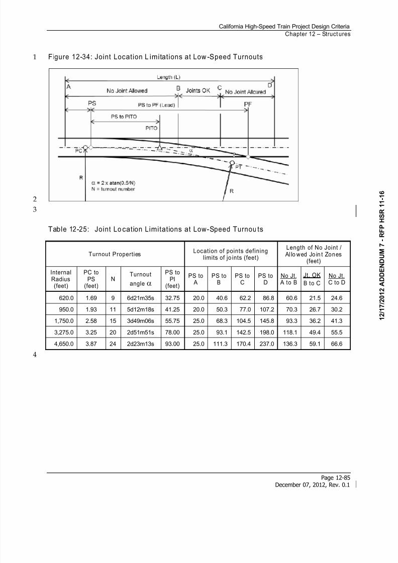
8/13/2019 California High-Speed Train Project Design Criteria
http://slidepdf.com/reader/full/california-high-speed-train-project-design-criteria 93/116
California High-Speed Train Project Design Criteria
Chapter 12 – Struct ures
Page 12-85December 07, 2012, Rev. 0.1
Figure 12-34: Joint Location L imitations at Low -Speed Turnouts1
2
3
Table 12-25: Joint Lo cation Limitations at Low-Speed Turnou ts
Turnout PropertiesLocation of points defining
limits of jo ints (feet)
Length of No Joint / Al lo wed Jo in t Zones
(feet)
InternalRadius(feet)
PC toPS
(feet)N
Turnout
angle
PS toPI
(feet)
PS to A
PS toB
PS toC
PS toD
No Jt. A to B
Jt. OK
B to C
No Jt.C to D
620.0 1.69 9 6d21m35s 32.75 20.0 40.6 62.2 86.8 60.6 21.5 24.6
950.0 1.93 11 5d12m18s 41.25 20.0 50.3 77.0 107.2 70.3 26.7 30.2
1,750.0 2.58 15 3d49m06s 55.75 25.0 68.3 104.5 145.8 93.3 36.2 41.3
3,275.0 3.25 20 2d51m51s 78.00 25.0 93.1 142.5 198.0 118.1 49.4 55.5
4,650.0 3.87 24 2d23m13s 93.00 25.0 111.3 170.4 237.0 136.3 59.1 66.6
4
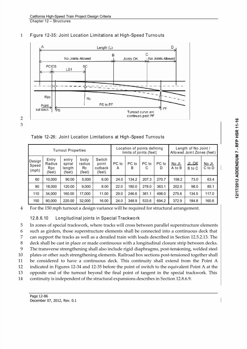
8/13/2019 California High-Speed Train Project Design Criteria
http://slidepdf.com/reader/full/california-high-speed-train-project-design-criteria 94/116
California High-Speed Train Project Design Criteria
Chapter 12 – Struct ures
Page 12-86December 07, 2012, Rev. 0.1
Figure 12-35: Joint Location Limitations at High-Speed Turno uts1
2
3
Table 12-26: Join t Location Limitation s at High -Speed Turn ou ts
Turnout PropertiesLocation of points defining
limits of joi nts (feet)Length of No Joint /
Al lo wed Jo in t Zones (feet )
DesignSpeed
(mph)
EntryRadius
Rpc(feet)
entryspirallength(feet)
bodyradius
Rc(feet)
Switchpoint
cutback(feet)
PC to A
PC toB
PC toC
PC toD
No Jt. A to B
Jt. OK
B to C
No Jt.C to D
60 10,000 90.00 5,000 6.00 24.0 134.2 207.3 270.7 158.2 73.0 63.4
80 18,000 120.00 9,000 8.00 22.0 180.0 278.0 363.1 202.0 98.0 85.1
110 34,000 160.00 17,000 11.00 29.0 246.6 381.1 498.0 275.6 134.5 117.0
150 80,000 220.00 32,000 16.00 24.0 348.9 533.6 694.2 372.9 184.8 160.6
For the 150 mph turnout a design variance will be required for structural arrangement.4
12.8.6.10 Lo ng itud inal join ts in Special Trackwo rk
In zones of special trackwork, where tracks will cross between parallel superstructure elements5
such as girders, those superstructure elements shall be connected into a continuous deck that6
can support the tracks as well as a derailed train with loads described in Section 12.5.2.13. The7
deck shall be cast in place or made continuous with a longitudinal closure strip between decks.8
The transverse strengthening shall also include rigid diaphragms, post-tensioning, welded steel9
plates or other such strengthening elements. Railroad box sections post-tensioned together shall10
be considered to have a continuous deck. This continuity shall extend from the Point A11
indicated in Figures 12-34 and 12-35 before the point of switch to the equivalent Point A at the12
opposite end of the turnout beyond the final point of tangent in the special trackwork. This13
continuity is independent of the structural expansions describes in Section 12.8.6.9.14
8/13/2019 California High-Speed Train Project Design Criteria
http://slidepdf.com/reader/full/california-high-speed-train-project-design-criteria 95/116
California High-Speed Train Project Design Criteria
Chapter 12 – Structures
Page 12-87December 07, 2012, Rev. 0.1
12.8.6.11 Bearings
AASHTO LRFD with Caltrans Amendments shall be used for design of bearings. Elastomeric1
bearings, disk bearings, spherical bearings and seismic isolation bearings are allowed. If seismic2
isolation bearings are used, the design shall follow the requirements of the Seismic chapter.3
Longitudinal and lateral restraints shall be placed to minimize eccentric deformations.4
The design life of bearings shall be as presented in the General chapter. Since bearings will be5
replaced during the life of the structures an inspection and replacement plan for bearings shall6
be provided. Inspection and replacement will be allowed only during the non-revenue service7
hours of the HST such that train operations are not affected by the inspection or replacement.8
12.8.6.12 Rail Stresses and Deformations of Aerial Structures
High-speed trains are very sensitive to deformations of the tracks. See Section 12.6 – Track-9
Structure Interaction for additional requirements related to track structure interaction,10
resonance and dynamic performance.11
12.8.6.13 Resonance of High Speed Trains on Repetitious Spans
Amplification of vibrations has been observed on high-speed trains traveling on long viaducts12
where the same span is repeated many times. It affects ride quality. In order to limit this13
response long viaducts shall have span length modified every 20 spans or 2000 feet. The14
modification shall include at least two spans reduced in length by 20 percent from the typical15
span between column centers. Following spans shall resume from the new column location16
rather than from the original column layout.17
12.8.6.14 Camber and Deflect ions for Aerial Trackway Structures
Structures shall be built with camber equal to the sum of deflections under dead load of steel18
structural components and permanent attachments (DC), dead load of non-structural and non-19
permanent attachments (DW), and one track of modified Cooper E-50 loading plus impact20
(LLRM+I)1.21
As a guide in design, the total long-term predicted camber growth, less deflection due to full22
dead load, shall be less than 1/5000 of the span length for prestressed concrete aerial structures23
measured 10,000 days after casting concrete. 24
To ensure rider comfort, the deflection of longitudinal girders under normal live load plus25
dynamic load allowance shall be as described in Section 12.6 – Track-Structure Interaction.26
12.8.6.15 Structure Deformation and Settlement
The control of deformations through proper structural design is of paramount importance in27
obtaining acceptable ride quality for the rail vehicles and passengers. Consider structure28
deformations, including foundation settlement, for their effects on structural behavior but also29
and on trackwork. As a minimum, trackway piers and abutments settlement as measured at the30
top of concrete of the finished trackway girder deck shall be limited as prescribed in the31
Geotechnical chapter.32
8/13/2019 California High-Speed Train Project Design Criteria
http://slidepdf.com/reader/full/california-high-speed-train-project-design-criteria 96/116
California High-Speed Train Project Design Criteria
Chapter 12 – Structures
Page 12-88December 07, 2012, Rev. 0.1
12.8.6.16 Superelevation on Aerial Structures
Superelevation of tracks through curved track shall be accomplished through the trackwork.1
Girder decks shall maintain a level attitude transverse to the track with deck slope allowed only2
for drainage.3
12.8.6.17 Walkways, Parapets, and Sound Walls
Loads on walkways shall be as described in Section 12.7.1.4. Walkways shall be precast or cast-4
in-place concrete. The walkway shall be on the cover of the cable trough. The cable trough cover5
shall be a non-skid material and the cover shall be anchored using positive connections to resist6
loads described Section 12.5. Walkways shall follow requirements on the Standard and7
Directive Drawings.8
Parapets shall be provided along edges of aerial structures, bridges, and HST grade separation9
structures. Parapets shall be designed for wind loads, slipstream effects, and other loadings in10
Section 12.5. Parapets shall be designed to accommodate installation of sound walls.11
Parapets and safety railings shall be designed to withstand the forces in Section 12.7.1.6. In12
locations where conduit risers are required along the alignment, parapets may be required to13
support conduits.14
Temporary railings may be necessary to provide safety after girders are placed and before15
parapets are placed. Temporary railings shall meet the same requirements as safety railings.16
Temporary railings may be needed between construction contracts.17
The height of sound walls shall be determined based on results from the noise attenuation18
study. The sound wall and its connection to the structure shall be capable of resisting the19
slipstream effects from passing trains and the wind load as described in Section 12.5. No gap20shall be permitted between the bottom of sound wall and the structure deck, nor any vertical21
gaps between the sound wall panels.22
12.8.7 Complex and Non-Standard Aerial Structures
For the definitions of standard, complex and non-standard structures see Seismic chapter. Some23
structures and structural systems involve unique design, construction, and performance24
problems not covered by these criteria. Some specific requirements follow:25
Straddle and outrigger bents have cap beams that extend beyond the edges of26
superstructure toward columns located outside of the superstructure.27 The load path necessary to accommodate longitudinal actions of the superstructure shall28
be defined in a report and submitted with the Type Selection Report to the Authority,29
see Section 12.8.1.30
Torsion cracking in the primary load path is not permitted in concrete beam members.31
Compatibility torsion is allowed.32
8/13/2019 California High-Speed Train Project Design Criteria
http://slidepdf.com/reader/full/california-high-speed-train-project-design-criteria 97/116
California High-Speed Train Project Design Criteria
Chapter 12 – Structures
Page 12-89December 07, 2012, Rev. 0.1
Torsional rotation of concrete columns is not permitted under seismic actions when high1
bending and shear stresses occur.2
12.8.8 Emergency Access
Where access stairs are provided, the emergency stairs shall be at the edge of deck. A safety gate3
opening away from the track shall be provided at each access opening. The safety gate shall be4
designed to resist wind and slipstream forces from Section 12.5 as well as live loads in Section5
12.7.6
12.8.9 OCS Pole and Traction Power Facili ty Gantry Supports
Girder decks shall be designed to accommodate and support OCS poles and Traction Power7
Facility Gantry. Loads are described in Section 12.5. Conduit or sleeves for future conduit shall8
be provided from external power sources to the OCS poles and Traction Power Facility Gantry.9
12.8.10 Maintenance of HST Aerial Structures, Bridges, and Grade Separations
Because of the large number of structures along the line, special care shall be taken in the design10
to reduce maintenance requirements. The following requirements shall apply:11
Reinforced or prestressed concrete structures are preferred over steel structures. The12
Designer shall justify in writing the use of steel structures, demonstrating the benefits of any13
steel structure.14
Bearings shall be easily accessible for inspection. They shall be adjustable and replaceable at15
any time during the life of the structure without disrupting train normal operations. Bearing16
replacement shall be completed within non-revenue hours. During this period train speed17may be limited at location where bearing is being replaced. The design documents shall18
provide a description of the procedures for bearing replacement, including the location of19
the jacks with safety nuts and a calculation of forces.20
Access arrangements for maintaining exterior surfaces or equipment attached thereto shall21
be provided from the ground or from movable gantries. At intervals not greater than 30022
feet and at one location in the case of a shorter isolated structure, 2.5 feet x 5 feet access23
openings with steel grating for inspection and maintenance shall be provided in the bottom24
slabs close to the expansion joint piers. For tall and long structure access openings may be at25
both ends near abutments.26
If a pier is not accessible from the ground beneath, such as river crossing bridge, a 3 feet x 327
feet access opening with steel grating shall be provided in the bottom slab of decks so that28
the pier top can be reached from the inside of the box girder. Beside this opening, a work29
platform shall be provided at the pier top for the maintenance of bearings.30
8/13/2019 California High-Speed Train Project Design Criteria
http://slidepdf.com/reader/full/california-high-speed-train-project-design-criteria 98/116
California High-Speed Train Project Design Criteria
Chapter 12 – Structures
Page 12-90December 07, 2012, Rev. 0.1
In the design of bridges, the vertical load of maintenance the gantry on the deck overhang1
shall be taken into consideration. The maintenance gantry shall be represented by a line load2
of 30 kips over a length of 13 feet applied to the edge of the cantilever deck.3
A lifting hook capable of lifting 7500 pounds shall be embedded in the underside of the4 superstructure top slab above each access opening. Access openings shall be equipped with5
lockable galvanized steel hatches.6
12.9 Requirements for Bridges not Supporting HST
Bridges not supporting HST are classified as either Primary Type 2 or Secondary in the Seismic 7
chapter. Secondary Bridges shall be designed to either the requirements of AASHTO LRFD with8
Caltrans Amendments for pedestrian and highway bridges, or AREMA Manual for Railway9
Engineering for railroad bridges. Primary Type 2 structures shall meet the requirements10
described below.11
12.9.1 Load Requirements for New Primary Type 2 Pedestr ian Bridges
New Primary Type 2 pedestrian bridges shall be designed according to AASHTO LRFD Guide12
Specifications for the Design of Pedestrian Bridges, with seismic design according to the Seismic 13
chapter.14
New Primary Type 2 pedestrian bridges shall not have expansion joints or other features15
requiring special maintenance in the HST right of way. Access shall be reserved for inspection16
and routine maintenance without impacting HST operations or endangering bridge17
maintenance inspectors.18
Local County, City, or third party bridges shall follow requirements of the local jurisdiction.19
12.9.2 Load Requirements for New Secondary Pedestr ian Bridges
Bridges or structures that support pedestrian loadings not spanning and classified as Secondary20
structures shall be designed according to AASHTO LRFD Guide Specifications for the Design of21
Pedestrian Bridges and with the seismic provisions of CSDC. OBE is not required unless seismic22
performance has the potential to directly impact HST service.23
12.9.2.1 Existing Pedestrian Bridges
Existing Primary Type 2 pedestrian bridges shall be evaluated to determine a Bridge Health24Index. HST horizontal and vertical clearances shall meet the clearance requirements specified25
in the Trackway Clearances chapter. Existing Primary Type 2 pedestrian bridges that are load26
restricted or a Bridge Health Index (Sufficiency Rating) less than 80 shall be replaced.27
For existing Primary Type 2 pedestrian bridges that do not meet seismic performance28
requirements according to the Seismic chapter, retrofit shall be required and a Seismic Design29
and Analysis Plan submitted as required in the Seismic chapter.30
8/13/2019 California High-Speed Train Project Design Criteria
http://slidepdf.com/reader/full/california-high-speed-train-project-design-criteria 99/116
California High-Speed Train Project Design Criteria
Chapter 12 – Structures
Page 12-91December 07, 2012, Rev. 0.1
12.9.2.2 Live Load or Pedestr ian Bridges
Areas where cash carts are used shall be designed to accommodate a point live load of 3501
pounds per wheel.2
Areas where station equipment will be transported shall be designed for a load of 2000 pounds3
spread over a square with sides of two feet.4
12.9.2.3 Frequency and Vibration Limits for Pedestr ian Bridges
Pedestrian bridges or structures shall meet the requirements for pedestrian comfort specified in5
Section 12.7.1.13 – Frequency and Vibration Limits.6
12.9.3 Requirements for Highway Bridges
Bridges or structures that support highway loadings not spanning over HST structures or7
alignments, shall be designed according to AASHTO LRFD with Caltrans Amendments and8
with the seismic provisions of CSDC and follow the Office of Specially Projects Information and9
Procedures Guide for Planning Studies and Type Selection to achieve approval from the10
Department of Transportation. County, city and other bridges shall follow requirements of11
these jurisdictions.12
12.9.3.1 New Highway Bridges
New highway bridges that are classified as Primary Type 2 structures shall be designed13
according to AASHTO LRFD with Caltrans Amendments and with seismic design following the14
requirements of the Seismic chapter and meeting the durability requirements herein in addition15
to requirements of the bridge owner.16
New Primary Type 2 highway bridges shall not have expansion joints or other features within17the HST right of way requiring maintenance. Access shall be reserved for safe inspection and18
normal maintenance of the highway bridge over the HST without impacting train operations or19
endangering bridge maintenance inspectors.20
Bridges supporting the California State Highway System (SHS) shall follow the procedures in21
the State of California Department of Transportation procedures described in the Office of22
Specially Projects Information and Procedures Guide for Planning Studies and Type Selection to23
achieve approval from the Department of Transportation. County, city and other bridges shall24
follow requirements of these jurisdictions in addition to the requirements herein.25
12.9.3.2 Existing Highway BridgesIn situations where HST must pass under an existing highway bridge and are thus classified as26
Primary Type 2 bridges, the highway bridge shall be evaluated for its continued service. Each27
bridge shall:28
be accepted as-is29
or, repaired or retrofitted to meet these criteria30
8/13/2019 California High-Speed Train Project Design Criteria
http://slidepdf.com/reader/full/california-high-speed-train-project-design-criteria 100/116
California High-Speed Train Project Design Criteria
Chapter 12 – Structures
Page 12-92December 07, 2012, Rev. 0.1
or replaced with a new bridge1
The determination of the appropriate selection starts with the current Caltrans Bridge Health2
Index to be provided by Caltrans. Structures that are load restricted or a Bridge Health Index3
(Sufficiency Rating) equivalent to or less than 80 shall need replacement. Bridge Health Index4 less than 90 shall require repair to bring the Index to above 98 prior to start of train service.5
The seismic performance requirements described in the Seismic chapter for Primary Type 26
bridges shall be satisfied. For existing SHS structures that do not meet HST structural or7
seismic performance requirements as described in the Seismic chapter, an As-Built assessment8
shall be performed based upon best available information and in accordance with HST for9
Primary Type 2 bridges and described in the Seismic Design and Analysis Plan required in the10
Seismic chapter. For structures not meeting these requirements a seismic retrofit shall be11
required. The proposed seismic retrofit shall be prepared according to the Seismic Design and12
Analysis Plan and reviewed by Caltrans and the Authority for agreement on a complete seismic13
retrofit strategy for both MCE and OBE risk levels and the corresponding performance14described in the Seismic chapter.15
The horizontal and vertical clearances shall be evaluated by the Contractor to meet the16
requirements in the Trackway Clearances chapter. Structures that cannot meet clearance17
requirements or cannot obtain variance approval shall require modification or replacement.18
Evaluation will consider if the bridge is structurally deficient or functionally obsolete.19
Continued operation of the “as is” facility, seismic retrofit/rehabilitation, or replacement will be20
made by the Authority in conjunction with the owner and the Contractor.21
Mitigation measures shall be considered for all existing structures. Such mitigations may22include modifying HST alignments to satisfy clearance envelopes; constructing track protection23
shields to keep structural debris from affecting train service; constructing catcher frames to24
support displaced existing girders to minimize impacts to HST due to post-seismic event25
recovery; and/or replacement of the existing structure.26
12.9.4 Requirements for New Railway Bridges
New Primary Type 2 railway bridges shall be designed according to AREMA and the27
requirements of the railroad owner and operator with seismic design according to the Seismic 28
chapter.29
New Primary Type 2 railway bridges shall not have expansion joints or other features requiring30
special maintenance in the HST right of way. Access shall be reserved for inspection and routine31
maintenance without impacting HST operations or endangering bridge maintenance inspectors.32
Existing freight rail bridges spanning over the HST right of way shall be inspected, assessed and33
evaluated to prepare a recommendation for either acceptance “as is”, seismic retrofit/repair, or34
8/13/2019 California High-Speed Train Project Design Criteria
http://slidepdf.com/reader/full/california-high-speed-train-project-design-criteria 101/116
California High-Speed Train Project Design Criteria
Chapter 12 – Structures
Page 12-93December 07, 2012, Rev. 0.1
replacement by the Contractor. The seismic requirements for a primary structure as defined in1
the Seismic chapter shall be followed.2
12.9.5 Requirements for Existing Railway Bridges
Existing Primary Type 2 railway bridges shall be evaluated to determine a Bridge Health Index.3
A Bridge Health Index of less than 80 shall require a bridge replacement. HST horizontal and4
vertical clearances shall meet the clearance requirements specified in the Trackway Clearances 5
chapter.6
For existing Primary Type 2 railway bridges that do not meet seismic performance requirements7
according to the Seismic chapter, retrofit shall be required and a Seismic Design and Analysis8
Plan submitted as required in the Seismic chapter.9
12.9.6 Intrus ion Protect ion
If a pedestrian, highway, or railway bridge column is located adjacent to the HST alignment,10then intrusion protection shall be provided. Barriers shall be designed to meet the requirements11
in Sections 12.5.2.14 and 12.7.1.9. Intrusion protection requirements are defined in the Rolling12
Stock and Vehicle Intrusion Protection chapter.13
12.10 Earth Retaining Structures
Earth retaining structures shall be designed to lateral earth pressures in accordance with the14
Geotechnical chapter. Top of retaining walls, including fill, cut, and trench walls, shall be at least15
1 foot above finish grade and provided with fall protection barriers as per Cal/OSHA. Wall16
heights may be higher as required for flood elevation and intrusion protection requirements.17Walls with Access Deterring (AD) or Access Restricting (AR) fencing, per the Civil chapter, can18
serve as fall protection provided that the fencing meets Cal/OSHA requirements.19
Temporary support excavation systems shall not be part of the permanent earth retaining20
structures.21
12.10.1 Earth Pressure Acting on Retaining Structures
For earth pressure acting on retaining structures, see the Geotechnical chapter.22
12.10.2 Retaining Walls
Retaining walls shall be designed in accordance with requirements of the Geotechnical chapter.23
Retaining walls shall be constructed with expansion joints in walls a maximum of 72 feet apart.24
Construction joints shall be a maximum of 24 feet apart.25
8/13/2019 California High-Speed Train Project Design Criteria
http://slidepdf.com/reader/full/california-high-speed-train-project-design-criteria 102/116
8/13/2019 California High-Speed Train Project Design Criteria
http://slidepdf.com/reader/full/california-high-speed-train-project-design-criteria 103/116
California High-Speed Train Project Design Criteria
Chapter 12 – Structures
Page 12-95December 07, 2012, Rev. 0.1
required in the Geotechnical reports described in the Geotechnical chapter. Sump structures shall1
be made water proof from ground water. Refer to the Drainage chapter.2
12.10.8 Trench Emergency Exits
Emergency exits are required from trenches at a minimum spacing of 2,500 feet. There shall be3
at least one emergency exit in each trench. The exit shall include an enclosed stairway from the4
walkway to ground surface and a secured head house at the surface.5
12.11 Cut-and-Cover Structures
The criteria set forth in this section govern the static load design of cut-and-cover underground6
structures with the exception of pile foundations. Cut-and-cover structures include line7
structures, crosspassages, sump pump structures, underground stations, vaults, ventilation8
structures, and other structures of similar nature. Portal and ventilation requirements and9
minimum cross sectional tunnel areas shall be as required in the Tunnels chapter.10
The design of structures within the scope of this section shall be in accordance with the11
provisions set forth in these criteria and shall also meet the requirements of the AASHTO LRFD12
with Caltrans Amendment, CBC, ACI, AISC and AWS, except where such requirements are in13
conflict with these criteria.14
12.11.1 Structural System
Structural system for cut-and-cover line structures shall be single and/or multi-cell reinforced15
concrete box structures, with walls and slabs acting one-way in the transverse direction to form16
a continuous frame. Temporary excavation support systems shall not be used as whole or part17of the permanent walls. Expansion or contraction joints are required at locations of major18
change in structural sections such as from line structure to station. Construction joints shall19
have continuous reinforcing steel, non-metallic waterstops and sealants.20
12.11.2 Loads and Forces
Components of underground structures shall be proportioned to withstand the applicable loads21
and forces described in Section 12.5.22
Cut-and-cover structures shall, at minimum, be designed for the forces described herein.23
12.11.2.1 Zone of Influence
Zone of Influence is defined as the area above a positive Line of Influence which is a line from24
the critical point of substructure at a slope of 2 horizontal to positive 1 vertical (line sloping25
towards ground level) or the area below a negative Line of Influence which is a line from the26
critical point of substructure at a slope of 2 horizontal to negative 1 vertical (line sloping away27
from ground level).28
8/13/2019 California High-Speed Train Project Design Criteria
http://slidepdf.com/reader/full/california-high-speed-train-project-design-criteria 104/116
California High-Speed Train Project Design Criteria
Chapter 12 – Structures
Page 12-96December 07, 2012, Rev. 0.1
12.11.2.2 Future Traffic Loads
An area surcharge applied at the ground surface both over and adjacent to underground1
structures is to simulate possible roadway and sidewalk live loads. This surcharge is intended2
to simulate conditions during future construction activities adjacent to the underground3
structures. Such construction may result in permanent loads or in temporary loads from4construction equipment from the stockpiling of construction materials, or from the deposition5
of excavated earth. It is possible that loads such as those from hauling trucks, may be applied6
inadvertently to the underground structures due to their innate inconspicuousness.7
12.11.2.3 Alternative Traffic Loading
For the underground structures beneath or adjacent to operating railroads, both the vertical and8
lateral surcharge shall be based on Cooper's E-80, defined by AREMA MRE, railroad surcharge9
loadings. Refer to the standards of the subject railway.10
For the underground structures adjacent to existing highway bridge overcrossings, both the11
vertical and lateral surcharge shall be based on the operating loads from the contractor's12equipment with a minimum surcharge loadings equivalent to a 100-ton crawler crane.13
For underground structures beneath highways, city streets or planned roadways, the applied14
vehicular live load shall be based on the HL-93 loading according to the AASHTO LRFD with15
Caltrans Amendments. For underground structures which are not anticipated to be beneath16
railroads, overcrossings, highways, streets, or roadways, the applied live load shall be based on17
no less than HL-93 loading according to the AASHTO LRFD with Caltrans Amendments. The18
distribution of this live load shall be in accordance with the following:19
Fill height less than two feet - live load shall be applied as concentrated loads directly to the20
top of the slab.21
Fill height greater than two feet - concentrated live loads shall be distributed over a square22
area, the sides of which shall equal 1.75 times the depth of the fill.23
When distribution areas overlap, the total load shall be uniformly distributed over an area24
defined by the outside limits of the individual areas.25
For design of the top slab of underground structures supporting the alternative traffic loading,26impact loading (I) shall conform to AASHTO LRFD with Caltrans Amendments, Article 3.6.2.2.27
The fill height shall be measured from the top of ground or pavement to the top of the28
underground structure.29
12.11.2.4 Existing Structures
Existing structures that are to remain in place above underground structures shall either be30
underpinned in such a manner as to avoid increased load on the underground section, or the31
section shall be designed to support the structure directly. Third party structures shall be32
supported directly on HST structures only with specific approval in writing by the Authority.33
8/13/2019 California High-Speed Train Project Design Criteria
http://slidepdf.com/reader/full/california-high-speed-train-project-design-criteria 105/116
California High-Speed Train Project Design Criteria
Chapter 12 – Structures
Page 12-97December 07, 2012, Rev. 0.1
Underground structures shall be designed for additional loading from existing adjacent1
buildings or structures unless they are permanently underpinned or have foundations to below2
the zone of influence. A building shall be considered to be adjacent to an underground structure3
when the horizontal distance from the building line to the nearest face of the underground4
structure is less than 2 times the depth of the underground structure invert below the building5foundation.6
Each existing structure shall be considered individually. In the absence of specific data for a7
given height of building and type of occupancy, applicable foundation loads shall be computed8
according to the CBC and the additional uniform lateral pressure on that portion of the9
underground structure sidewall below the elevation of the building foundation shall be10
distributed as shown on the preliminary engineering drawings. If distribution is not indicated11
on the preliminary engineering drawings, designer shall determine distribution.12
12.11.2.5 Requirements for Future Structures
Some cut-and-cover structures must be designed to accommodate future structures in close13proximity. Guidelines are provided below for a general case. Additional requirements may be14
required on a case-by-case basis.15
A. Clearance
Structures over or adjacent to HST underground structures shall be designed and constructed16
so as not to impose any temporary or permanent adverse effects on underground structures.17
The minimum clearance between any part of the adjacent structures to exterior face of18
substructures shall be 7 feet–6 inches. Minimum cover of 8 feet shall be maintained wherever19
possible.20
B. SurchargeIn general, cut-and-cover structures are designed with an area surcharge applied at the ground21
surface both over and adjacent to the structures. The area surcharge is considered static uniform22
load with the following value:23
D (feet) Addi tional Average Vertical Loading (psf )
D>20 0
5<D<20 800-40D
D<5 600
24
Where D is the vertical distance from the top of the underground structure roof to the ground25
surface.26
C. Shoring
Shoring is required for excavations in the Zone of Influence. Zone of Influence is defined in27
Section 12.11.2.1.28
8/13/2019 California High-Speed Train Project Design Criteria
http://slidepdf.com/reader/full/california-high-speed-train-project-design-criteria 106/116
California High-Speed Train Project Design Criteria
Chapter 12 – Structures
Page 12-98December 07, 2012, Rev. 0.1
D. At-Rest Soil Condition
See the Geotechnical chapter for soil loads and pressures needed for design.1
E. Soil Redistribution
See the Geotechnical chapter for soil redistribution caused by temporary shoring or permanent2 foundation system.3
F. Dewatering
Dewatering shall be monitored for changes in groundwater level. Recharging will be required if4
existing groundwater level is expected to drop more than 2 feet.5
G. Piles Predrilled
Piles shall be predrilled to a minimum of 10 feet below the Line of Influence. Piles shall be6
driven in a sequence away from HST structures. No pile will be allowed between steel-lined7
tunnels.8
H. Vibration During Pile Driving
Underground structures shall be monitored for vibration during pile driving operations for9
piles within 100 feet of the structures. Tunnels shall also be monitored for movement and10
deformation. Requirements for monitoring will be provided upon request.11
I. Future Excavation Adjacent to Cut-and-Cover
The design of cut-and-cover structures shall consider an unbalanced lateral load condition due12
to possible future excavation or scour of 30 percent of total depth on one side of the structure.13
The designer shall, as a minimum, demonstrate by analysis that under this condition the14
structures will remain stable with an adequate margin of safety.15
12.11.2.6 Earth Pressure
A. Vertical Earth Pressure
Depth of cover shall be measured from the ground surface or roadway crown, or from the street16
grade, whichever is higher, to the top of underground structure surface. Saturated densities of17
soils shall be used to determine the vertical earth pressure. Recommended values shall be18
presented in the Geotechnical reports described in the Geotechnical chapter.19
B. Lateral Earth Pressure
For the purpose of these criteria, cut-and-cover box sections are defined as structures with stiff20
walls, which are restrained at the top so that the amount of deflection required to develop active21
pressure is not possible. See the Geotechnical chapter for earth pressures required for design.22
12.11.2.7 Hydrostatic Pressure (Buoyancy)
The effects of hydrostatic uplift pressure shall be considered whenever ground water is present.23
The hydrostatic uplift pressure is a function of the height of water table above the foundation24
plane, and shall be assumed uniformly distributed across the width of the foundation in25
proportion to the depth of the base slab below the design ground water table.26
8/13/2019 California High-Speed Train Project Design Criteria
http://slidepdf.com/reader/full/california-high-speed-train-project-design-criteria 107/116
California High-Speed Train Project Design Criteria
Chapter 12 – Structures
Page 12-99December 07, 2012, Rev. 0.1
Structures shall be checked for both with and without buoyancy to determine the governing1
design condition. Maximum design flood levels are indicated in the Hydrology Report. If the2
Hydrology Report is not part of the preliminary engineering documents provided by the3
Authority, the Designer (or its Geotechnical Engineer) shall determine applicable levels.4
12.11.2.8 Flotation
For design flood levels and flood zone, see the Hydrology Report, if applicable.5
Cut-and-cover structures subject to ground water table and/or located within the flood zone6
shall be checked and provided with adequate resistance to flotation.7
No permanent dewatering system shall be assumed for the design of underground cut-and-8
cover structures.9
A. Factor of Safety
The structure shall have a minimum factor of safety against flotation at any construction stage10
of 1.05, excluding any benefit from skin friction from perimeter of the structures.11
The structure, when complete, shall have a minimum factor of safety against flotation at up to12
the 100-year flood level of 1.10 excluding skin frictional from perimeter of the structures.13
The use of tiedowns, tension piles or other elements specifically designed to resist uplift forces14
shall be permitted and included in the flotation calculations. See Geotechnical chapter for other15
requirements buoyancy resisting elements.16
The dead weight of the structure used in the flotation calculations for the underground17
structures shall exclude the weight of:18
Any building above the structure,19
Any live load internal or external to the structure,20
Any loads which is not be effective at the time, and21
2 feet of backfill over the roof except when checking against the 100-year and 500-year flood22
levels.23
12.11.2.9 Miscellaneous Loads
A. Cut-and-Cover Walkway Cover Live Loads
Stationary and hinged cover assemblies shall be designed for the loads on walkways per Section2412.7.1.4. Deflection at center of span under 100 pounds per square foot uniform live load shall25
not be more than 1/8 inch. Hinged cover material shall comply with NFPA 130 requirements.26
B. Live Loads and Equipment Loads for Ventilation Structures
See Section 12.7 – Structural Design of Surface Facilities and Buildings, for roof and floor live27
loads and equipment loads for ventilation structures.28
8/13/2019 California High-Speed Train Project Design Criteria
http://slidepdf.com/reader/full/california-high-speed-train-project-design-criteria 108/116
California High-Speed Train Project Design Criteria
Chapter 12 – Structures
Page 12-100December 07, 2012, Rev. 0.1
12.11.2.10 Seismic Design of Underground Structures
See the Seismic chapter for the demand requirements for seismic design of tunnels and1
underground structures. If ductility is required to meet seismic demands in underground2
structure, then the requirements provided in CSDC for lateral confinement reinforcing of3
concrete pier walls shall be satisfied.4
12.11.2.11 Reinforced Concrete Box Station Sections
Underground station structures and their appurtenant structural elements such as entrances5
shall be designed in accordance with AASHTO LRFD with Caltrans Amendments referenced6
AASHTO specifications.7
Subsurface exploration shall be carried out to determine the presence and influence of geologic8
and environmental conditions that may affect the performance of station structures and9
reported by one or more Geotechnical reports described in the Geotechnical chapter.10
Load combinations and load factors to be used are those provided in this chapter. Load11resistant factors to be used are those provided by AASHTO LRFD with Caltrans12
Amendments and their referenced AASHTO Tables 3.4.1-2, 3.4.1-3, and 12.5.5-1. In addition,13
the effects of EH, EV, ES, LS, DD, DW, and WA shall be applied simultaneously in all their14
maximum and minimum values to produce the envelope of moment, torsion, shear, and15
axial force to produce the greatest demands to the structural framing. These load values16
shall cover the forces on the station structure at all phases of construction. See AASHTO17
LRFD with Caltrans Amendments Section 5.14.2.3.18
Final ground induced pressures and design assumptions for soil-structure interaction19
shall be provided by the Geotechnical reports described in the Geotechnical chapter.20
Vertical pressure on foundation slabs may be divided into hydrostatic and earth pressure21
components. The hydrostatic component shall be distributed across the width of the22
foundation in proportion to the depth of each portion of the basic slab below the design23
groundwater table.24
Distribution of the earth pressure moment shall be based on specified construction25
procedures, and will include elastic and plastic subgrade reaction foundation effects.26
For design, the horizontal earth pressure distribution diagram for multiple braced flexible27
walls shall be the trapezoidal pressure diagram as given by the Contractor’s Geotechnical28
Engineer. Compression forces shall not be considered in shear design of the top and bottom29
slab in box sections.30
12.11.2.12 Reinforced Concrete
Concrete for cut-and-cover structures shall be designed to attain the required chemical31
resistance to the environment, low permeability, water tightness and water absorption as32
specified in accordance with the Durability Report.33
8/13/2019 California High-Speed Train Project Design Criteria
http://slidepdf.com/reader/full/california-high-speed-train-project-design-criteria 109/116
California High-Speed Train Project Design Criteria
Chapter 12 – Structures
Page 12-101December 07, 2012, Rev. 0.1
Concrete mixes shall be tested for acceptance by the selected Quality Assurance organization in1
accordance with the Quality Assurance Plan procedures to conform to the requirements.2
Concrete for cut-and-cover structures shall also meet the requirements of the Standard3
Specifications, and the following minimum requirements:4
Strength – Minimum f’c shall be 4000 psi at 28 days.5
Proportioning Materials – The maximum water-cement ratio shall be 0.40 with 4.5 percent to6
7.5 percent air entrainment.7
12.11.2.13 Reinforc ing Steel
Reinforcing steel in structural components shall use Customary U.S. Units, meet the8
requirements of the Standard Specifications, and meet the following requirements:9
Use reinforcing steel conforming to ASTM designation A 706 Grade 60 (Fy=60 ksi).10
Use uncoated reinforcing steel and welded wire fabric when the concrete surface is not in11contact with soil/water (or waterproofing).12
Use epoxy coated reinforcing steel meeting the requirements of the Standard Specifications13
for all permanent concrete members when the concrete surface is in contact with soil/water14
(or waterproofing).15
Spacing of main reinforcement shall not exceed 12 inches.16
12.11.2.14 Camber
The tunnel roof shall be cambered to mitigate the effect of long term loads (i.e., slab plus17
backfill). The camber shall be calculated in accordance with the AASHTO LRFD with Caltrans18
Amendments, Article 5.7.3.6. In computing the long-time deflection it shall be no less than the19
immediate deflection multiplied by a factor of 2.20
12.11.3 Waterproofing of Underground Station Structures
Roofs, walls, and floors slabs of underground station including auxiliary spaces except as21
otherwise noted, shall be waterproofed. To ensure adequate inspection and long term22
performance, no blind side waterproofing shall be used.23
Provisions shall be made to collect and drain water potentially seeping through the roof, walls,24
or floor. The leakage through structural elements shall be limited to a maximum of 0.001 gallon25
per square feet of structure per day, and no dripping or visible leakage from a single location shall be26permitted. 27
The manufacturer and installer of the waterproofing system shall submit a list of a minimum of28
five successful projects of similar design and complexity completed within the past five years.29
The designer shall design for any openings or other penetrations through the waterproofing30
layer and for appropriate protection measures for the waterproofing membrane including the31
8/13/2019 California High-Speed Train Project Design Criteria
http://slidepdf.com/reader/full/california-high-speed-train-project-design-criteria 110/116
California High-Speed Train Project Design Criteria
Chapter 12 – Structures
Page 12-102December 07, 2012, Rev. 0.1
chamfering of corners of the structure, external protection, etc. Components of the1
waterproofing system shall comply with applicable Volatile Organic Compound (VOC)2
regulations.3
12.11.3.1 Underground Station Structures
A. Roofs
Station roofs shall be completely waterproofed. Waterproofing and the boundary condition4
details at reglets and flashings shall be provided.5
B. Walls
Exterior station walls shall be completely waterproofed. Mezzanine walls enclosing public areas6
and entrance walls shall be furred out, and provisions shall be made for collecting and draining7
seepage through these walls. The depth of the furring shall be governed by the space required8
for the placing of fare collection and other equipment, and architectural requirements, such as9
the minimum thickness of the wall finish. The fastening of the finish to the wall shall be such10
that water can drain off the walls freely and that it will not corrode the fasteners.11
C. Floor Slabs
For station floor slabs, no special waterproofing provisions shall be made where the water can12
drain freely into the floor drainage system, and where such a leakage and drainage is not13
objectionable from a corrosion, operational, or visual standpoint.14
Drainage shall be provided at public areas of the station floor slab.15
D. Base Slabs
Waterproofing shall be applied under station base slab.16
E. Appendages
Differential vertical movements of the station body and its appendages, such as wings or17
entrances at shafts, due to ground re-expansion as a result of returning of ground water, may18
cause cracks at joints and other locations. Special attention shall be given to design detailing to19
mitigate this problem. Where such movements cannot be avoided, properly designed20
waterproof joints between such appendages and the station body shall be provided.21
12.11.3.2 Cut-and-Cover Underground Trackway Structures
A. Cut-and-Cover Box
Exterior membrane waterproofing shall be applied to the outside of the cut-and-cover box as22
indicated on the Standard and Directive Drawings. Any seepage through the walls or the floor23
shall be carried away by the track drainage.24
B. Transition Structure
For underground structure daylight transition structures, where U-sections or trenches with25
exposed sidewalls are used, special attention shall be given to controlling shrinkage cracks in26
sidewalls between construction joints.27
8/13/2019 California High-Speed Train Project Design Criteria
http://slidepdf.com/reader/full/california-high-speed-train-project-design-criteria 111/116
California High-Speed Train Project Design Criteria
Chapter 12 – Structures
Page 12-103December 07, 2012, Rev. 0.1
C. Rooms
The following rooms or spaces shall be completely waterproofed, including all wall and roof1
surfaces in contact with the earth. Floor drains shall be provided. Refer to the Mechanical 2
chapter.3
Electrical Rooms (includes spaces that house train control facilities, substation facilities,4
switchgear, ventilation fans, pumps, and other electrical equipment)5
Train Control and Auxiliary Equipment Rooms6
Substation , Switchgear, Fan Rooms, and Similar Equipment Rooms7
D. Pump Rooms
Floor drains shall be provided to prevent the accumulation of seepage as required in the8
Mechanical chapter.9
E. Cross-passages and Emergency Exits
Cross-passages shall be provided between tracks at every 2500 feet.10
12.11.3.3 Waterstops and Sealants
Waterstops and sealants shall be used in construction joints in exterior walls, floors, and roofs.11
12.11.3.4 Waterproofing Materials
Bentonite waterproofing shall not be used.12
12.11.3.5 Water tightness
The cut-and-cover structure shall be designed and constructed so that it achieves a functional13waterproofed underground structure for the duration of its design life. The design,14
construction, and maintenance of the cut-and-cover structure shall meet the water-tightness15
criteria stipulated below until substantial completion and acceptance by the Authority:16
Local infiltrations limit 0.002 gallons per square foot of structure per day and no dripping or17
visible leakage from a single location shall be permitted.18
No drips shall be permitted overhead or where they have the potential to cause damage to19
equipment, malfunctioning of any electrical power, signaling, lighting, control,20
communication equipment, or compromise electrical clearances.21
A drainage system shall be provided to accommodate water infiltration as specified herein22in accordance with tunnel and portal drainage.23
No water ingress shall cause entry of soil particles into the tunnel.24
No material used in preventing or stemming water ingress shall compromise the fire safety25
of the works or the durability of the structures in which they are used.26
8/13/2019 California High-Speed Train Project Design Criteria
http://slidepdf.com/reader/full/california-high-speed-train-project-design-criteria 112/116
California High-Speed Train Project Design Criteria
Chapter 12 – Structures
Page 12-104December 07, 2012, Rev. 0.1
Embedded electrical boards, electrical conduits, and other similar elements shall be1
completely waterproofed and watertight.2
The interface between cut-and-cover structure section with bored tunnel and other3
structures, (i.e., building structures, emergency egress structures, etc.) shall be designed and4
constructed such that the joint between the two structures is fully watertight.5
12.11.4 Water Holding and Conveyance Structures
Water conveyance or water holding structures that cross the HST alignment shall be designed6
to meet ACI 350 Code Requirements for Environmental Structures and Commentary with all7
Errata. The jurisdiction owning or operating the facility may have additional requirements that8
shall be followed.9
12.11.5 Shoring Systems
For specific requirements of soil loadings see the Geotechnical chapter. The design of the support10system shall consider several factors, including, but not limited to the following:11
Soil and groundwater conditions12
Width and depth of excavation13
Configuration of the structure to be constructed within the cut14
Size, foundation type and proximity of adjacent structures15
Utilities crossing the excavation, or adjacent to the excavation16
Requirements for traffic decking across the excavation17
Traffic and construction equipment surcharge adjacent to the excavation18
Settlements of adjacent structures19
Noise restrictions20
12.11.6 Structural Fire Resistance
Underground structures can be exposed to extreme events such as fires resulting from incidents21
inside the structure. Underground structure design shall consider the effects of a fire on the22
concrete supporting elements. The concrete elements should be able to withstand the heat of the23
specified fire intensity given in the Tunnels chapter and period of time without loss of structural24 integrity. Protection from fire shall be determined by concrete cover on the reinforcing,25
additional finish, and special treatment of the concrete mixes.26
8/13/2019 California High-Speed Train Project Design Criteria
http://slidepdf.com/reader/full/california-high-speed-train-project-design-criteria 113/116
California High-Speed Train Project Design Criteria
Chapter 12 – Structures
Page 12-105December 07, 2012, Rev. 0.1
12.12 Support and Underpinning of Structures
This section includes design requirements for the support and underpinning of existing1
structures to remain over or adjacent to new HST facilities.2
The designer, in coordination with the Authority, shall investigate existing structures, which are3to remain over, or adjacent to, the construction sites of new HST facilities. The designer shall4
prepare the necessary designs for the protection or permanent support and underpinning of5
such existing structures.6
The types of buildings and structures, which require support and underpinning, include the7
following:8
Buildings and structures that extend over the HST structures to such an extent that they9
must be temporarily supported during construction and permanently underpinned.10
Buildings and structures immediately adjacent to the HST structures that will require11 temporary support during construction.12
Buildings and structures that are affected by groundwater lowering. In certain areas,13
uncontrolled lowering of the groundwater for HST construction can cause settlements of14
buildings either adjacent to or at some distance from HST excavations.15
The design shall conform to the applicable requirements of the AASHTO LRFD with Caltrans16
Amendments (where highway bridges are involved), AREMA (where railway bridges are17
involved), CBC (where buildings are involved), ACI, AISC and AWS except where such18
requirements conflict with the criteria.19
12.12.1 Depth of Support Structures
Underpinning walls or piers which support buildings or other structures and which also form a20
portion of the excavation support system shall extend to a minimum depth of two feet below21
the bottom elevation of the excavation.22
12.12.2 Methods
Methods used to protect or underpin buildings or other structures shall take the site-specific soil23
conditions into consideration.24
12.12.2.1 Protect ion Wall Method of Structure Protection
Under some soil conditions, the supporting system for the excavation is sufficient to protect25
light structures. Under heavier loading conditions, a reinforced concrete cutoff wall,26
constructed in slurry-filled trenches or bored pile sections braced with preloaded struts, may be27
considered as an alternative to underpinning or as a means to avoid settlement due to28
dewatering.29
8/13/2019 California High-Speed Train Project Design Criteria
http://slidepdf.com/reader/full/california-high-speed-train-project-design-criteria 114/116
California High-Speed Train Project Design Criteria
Chapter 12 – Structures
Page 12-106December 07, 2012, Rev. 0.1
12.12.2.2 Stabilization of Soil
Soil stabilization techniques such as compaction grouting may be considered as alternatives in1
lieu of underpinning. Refer to Geotechnical chapter for soil stabilization.2
12.12.2.3 Temporary Bracing Systems
A tight bracing system is important for the effectiveness of underpinning and for protection3
wall support. In addition to the general requirements for support of excavations, which are4
provided in the specifications, the designer shall indicate special requirements for the5
installation and removal of the temporary bracing systems that relate to the designs of6
underpinning and protection walls, such as the levels of bracing tiers, the maximum distances7
of excavation below an installed brace, and the amount of preloading. The designer shall8
require that detailed design of the temporary bracing system be the responsibility of the9
contractor. Refer to the Geotechnical chapter for earth pressures.10
12.12.2.4 Pier, Pile, or Caisson Method of Underpinn ing
If soil conditions, structure size and proximity to an excavation dictate piers, piles or caissons11
for underpinning of an existing structure, such piers, piles, or caissons shall extend below a12
sloping plane which is defined as follows: The plane passes through a horizontal line which is13
located two feet below the bottom of the excavation, and which is also located within the14
vertical plane containing the face of that excavation closest to the structure foundation to be15
underpinned; the plane shall slope upwards and away from the excavation at an inclination16
which shall be established by the designer, on a case-by-case basis. The supports shall be17
founded on stable soil mass and extended beyond the slope of the soil wedge failure plane.18
Refer to the Geotechnical chapter for soils information.19
12.12.2.5 Temporary Shoring and Underpinn ingFor temporary shoring and underpinning of the existing operating structures, seismic loads20
shall be considered in the shoring and underpinning design. The soil and inertia lateral seismic21
design loads shall be determined by geotechnical engineers using requirements. For seismic22
requirements of temporary shoring and underpinning, see the Seismic chapter. Shoring shall be23
required to maintain at-rest soil condition and monitored for movement.24
12.13 Areas of Potential Explosion
Areas of new buildings adjacent to facilities where the public has access or that cannot be25
guaranteed as a secure area, such as parking garages and commercial storage and warehousing,26shall be treated as areas of potential explosion.27
NFPA 130, Standard for Fixed Guideway Transit and Passenger Rail Systems, life safety28
separation criteria shall be applied that assumes such spaces contain Class-I flammable or Class-29
II or Class-III combustible liquids. For structural and other considerations, separation and30
isolation for blast shall be treated the same as for seismic, and the more restrictive requirement31
shall be applied.32
8/13/2019 California High-Speed Train Project Design Criteria
http://slidepdf.com/reader/full/california-high-speed-train-project-design-criteria 115/116
California High-Speed Train Project Design Criteria
Chapter 12 – Structures
Page 12-107December 07, 2012, Rev. 0.1
12.14 Structure Interface Issues
The design of aerial structures shall accommodate the requirements for safe operation of trains.1
Design of structures shall provide for interface with all other design elements.2
12.14.1 Cable Trough
A cable trough shall be provided on both sides of the trackway. The cable trough shall be3
continuous through the entire system. The top of the cable trough shall be used as a safety4
walkway as a non-skid surface is provided.5
12.14.2 Grounding and Bonding
Refer to the Grounding and Bonding Requirements chapter for grounding and bonding design of6
structures including, but not limited to the following:7
Aerial structures and bridges8 Trenches and retaining walls9
Cut-and-cover structures10
Buildings and support facilities11
New and existing third party structures12
Miscellaneous structures (e.g., cable trough, sound wall, etc.)13
12.14.3 Drainage
Water shall be drained from the trackway and conveyed to the drainage system. See the14Drainage chapter for drainage requirements.15
12.14.4 Conduit Risers
Provisions shall be made for the installation of conduit up the sides of specific columns of aerial16
structures, walls of earth retaining structures, and walls of cut-and-cover structures. Further,17
details shall be provided for the installation such that no damage is inflicted on the columns,18
parapets, or walls.19
12.14.5 Embedded Conduits
Sleeves shall be embedded in the cable trough and parapet to provide routing for future electric20
cable installation.21
12.14.6 Trackside Equipment
Provisions shall be made to support trackside equipment. This equipment shall be located in22
line with the OCS poles.23
8/13/2019 California High-Speed Train Project Design Criteria
http://slidepdf.com/reader/full/california-high-speed-train-project-design-criteria 116/116
California High-Speed Train Project Design Criteria
Chapter 12 – Structures
12.14.7 Access Stairs
Access stairs shall be provided to the trackway from the ground surface in trenches, retained1
cuts, and cut-and-cover structures. The stairs and entrances shall be secured with fences and2
gates described in the Civil chapter. Minimum width of access stairs shall be 5 feet.3
12.14.8 Overhead Concrete Anchors
These criteria apply to anchors for overhead applications and subjected to sustained tensile4
loads where failure of the anchor could result in risk to life or limb.5
Anchors shall be embedded in confined concrete. Length of embedment in unconfined concrete6
shall not be considered effective embedment length.7
Use of adhesive anchors in overhead applications or in sustained tension is prohibited.8
12.14.9 UtilitiesFor utility requirements within HST structures, refer to the Utilities chapter.9