Embed Size (px)
Citation preview
8/4/2019 Cam Shaft Gear Presentation
http://slidepdf.com/reader/full/cam-shaft-gear-presentation 1/43
Presented By-S.K.Srivastava
Camshaft GearFor
ALCO Engine
8/4/2019 Cam Shaft Gear Presentation
http://slidepdf.com/reader/full/cam-shaft-gear-presentation 2/43
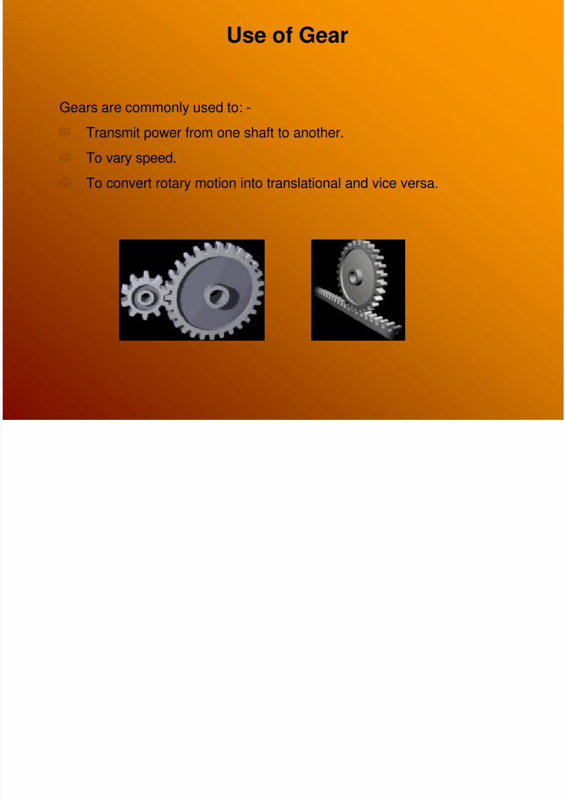
Gears are commonly used to: -
Transmit power from one shaft to another.
To vary speed.
To convert rotary motion into translational and vice versa.
Use of Gear
8/4/2019 Cam Shaft Gear Presentation
http://slidepdf.com/reader/full/cam-shaft-gear-presentation 3/43
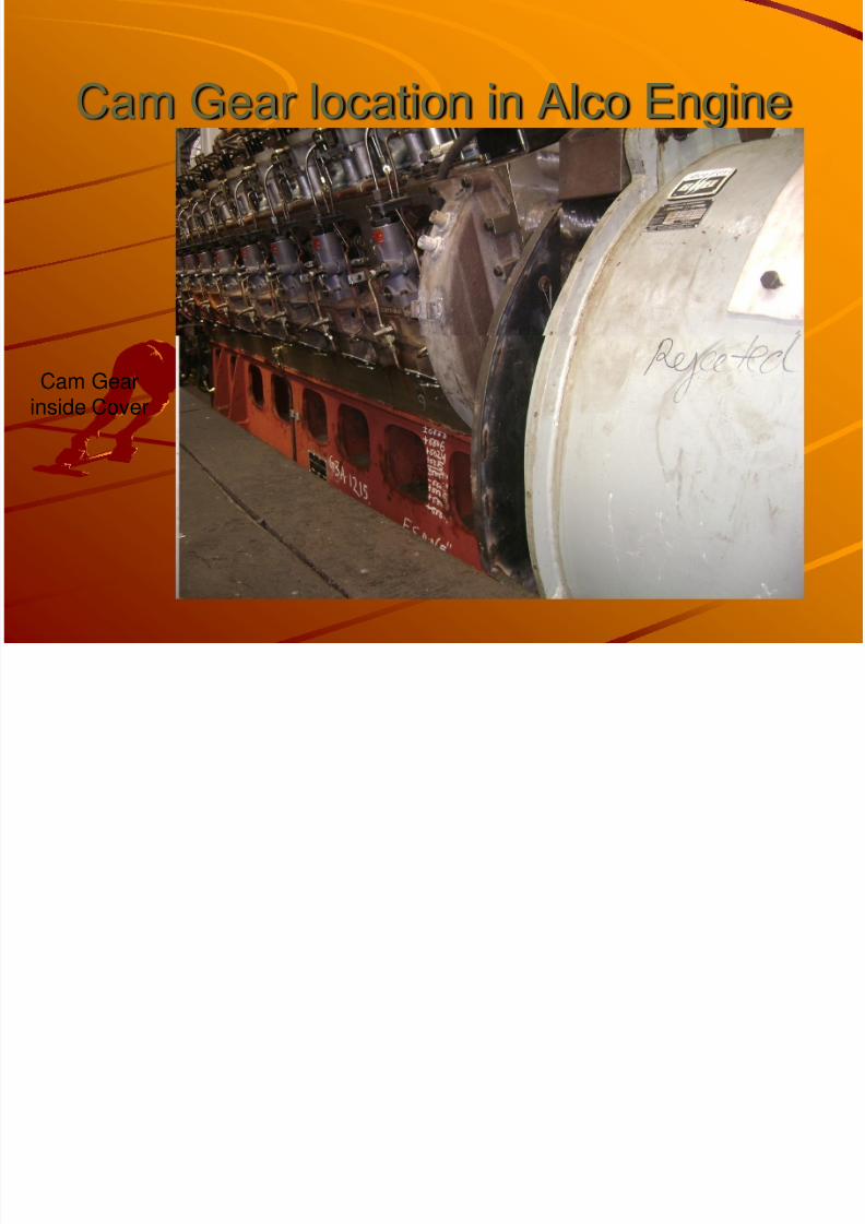
Cam Gear location in Alco Engine
Cam Gearinside Cover
8/4/2019 Cam Shaft Gear Presentation
http://slidepdf.com/reader/full/cam-shaft-gear-presentation 4/43
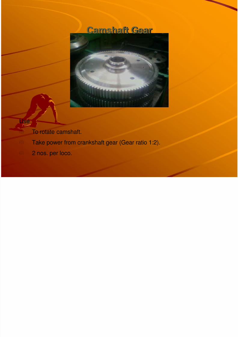
Camshaft Gear
Use
To rotate camshaft.
Take power from crankshaft gear (Gear ratio 1:2).
2 nos. per loco.
8/4/2019 Cam Shaft Gear Presentation
http://slidepdf.com/reader/full/cam-shaft-gear-presentation 5/43
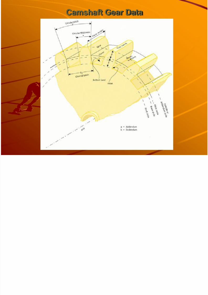
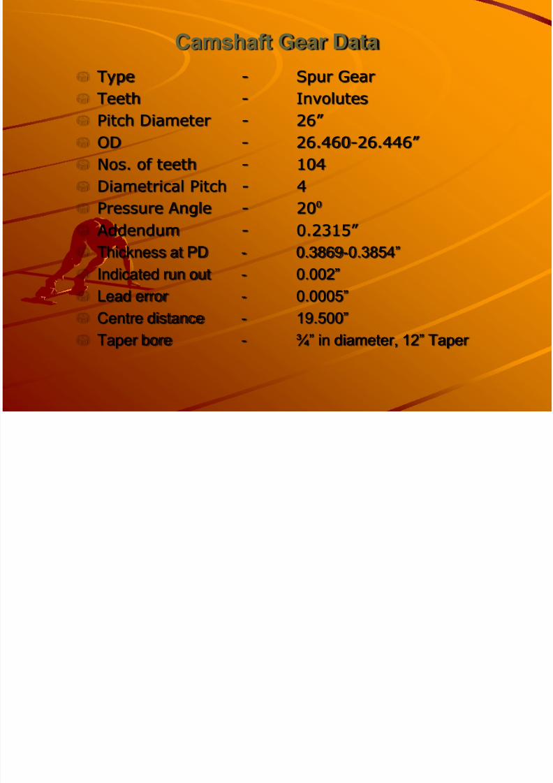
Camshaft Gear Data
8/4/2019 Cam Shaft Gear Presentation
http://slidepdf.com/reader/full/cam-shaft-gear-presentation 6/43
Camshaft Gear DataType - Spur Gear
Teeth - InvolutesPitch Diameter - 26” OD - 26.460- 26.446” Nos. of teeth - 104
Diametrical Pitch - 4Pressure Angle - 20 Addendum - 0.2315” Thickness at PD - 0.3869- 0.3854” Indicated run out - 0.002” Lead error - 0.0005” Centre distance - 19.500” Taper bore - ¾” in diameter, 12” Taper
8/4/2019 Cam Shaft Gear Presentation
http://slidepdf.com/reader/full/cam-shaft-gear-presentation 7/43
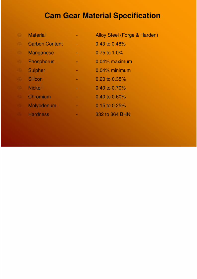
Cam Gear Material Specification
Material - Alloy Steel (Forge & Harden)Carbon Content - 0.43 to 0.48%
Manganese - 0.75 to 1.0%
Phosphorus - 0.04% maximum
Sulpher - 0.04% minimum
Silicon - 0.20 to 0.35%
Nickel - 0.40 to 0.70%
Chromium - 0.40 to 0.60%
Molybdenum - 0.15 to 0.25%
Hardness - 332 to 364 BHN
8/4/2019 Cam Shaft Gear Presentation
http://slidepdf.com/reader/full/cam-shaft-gear-presentation 8/43
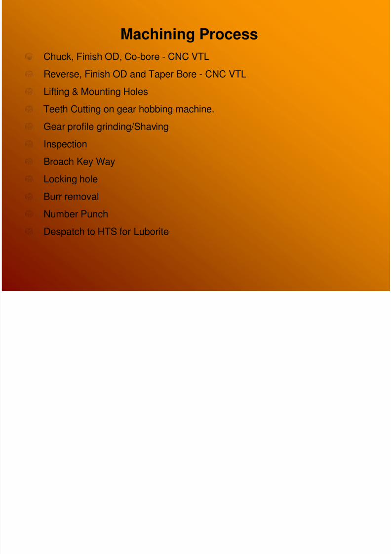
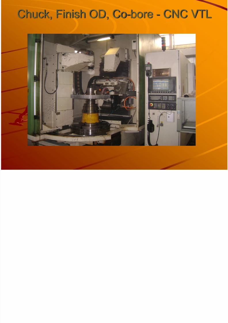
Machining ProcessChuck, Finish OD, Co-bore - CNC VTL
Reverse, Finish OD and Taper Bore - CNC VTL
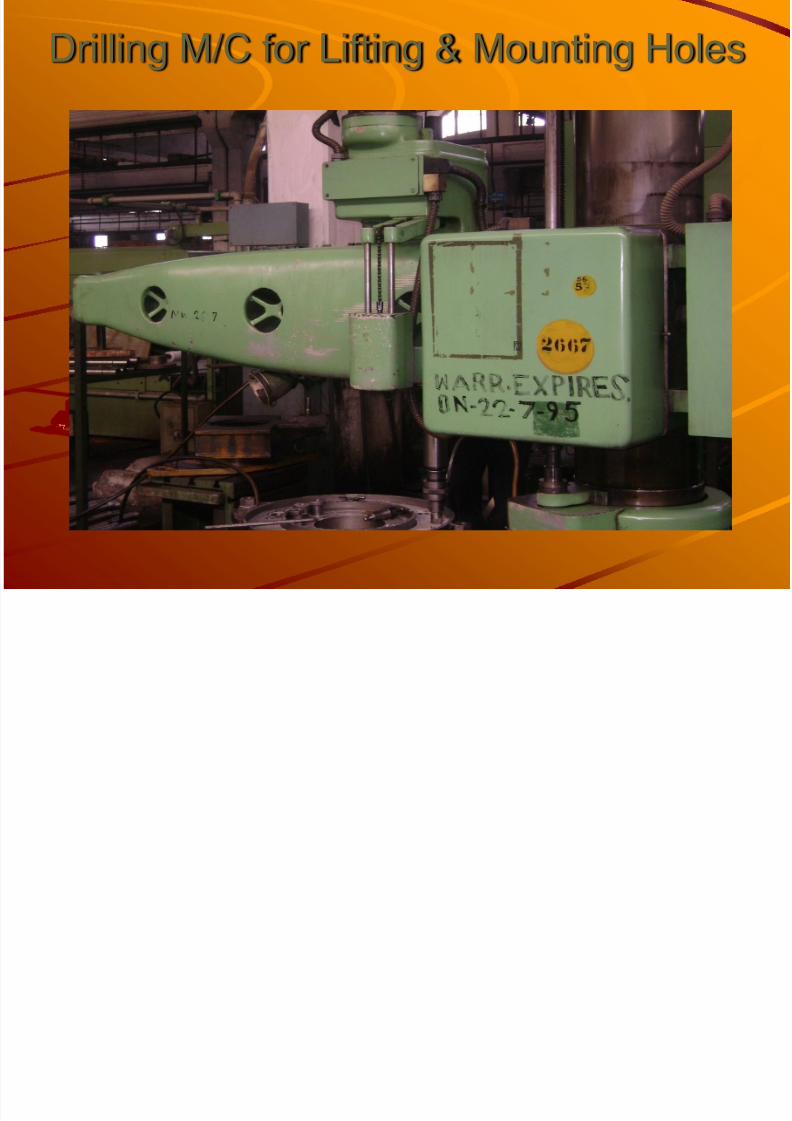
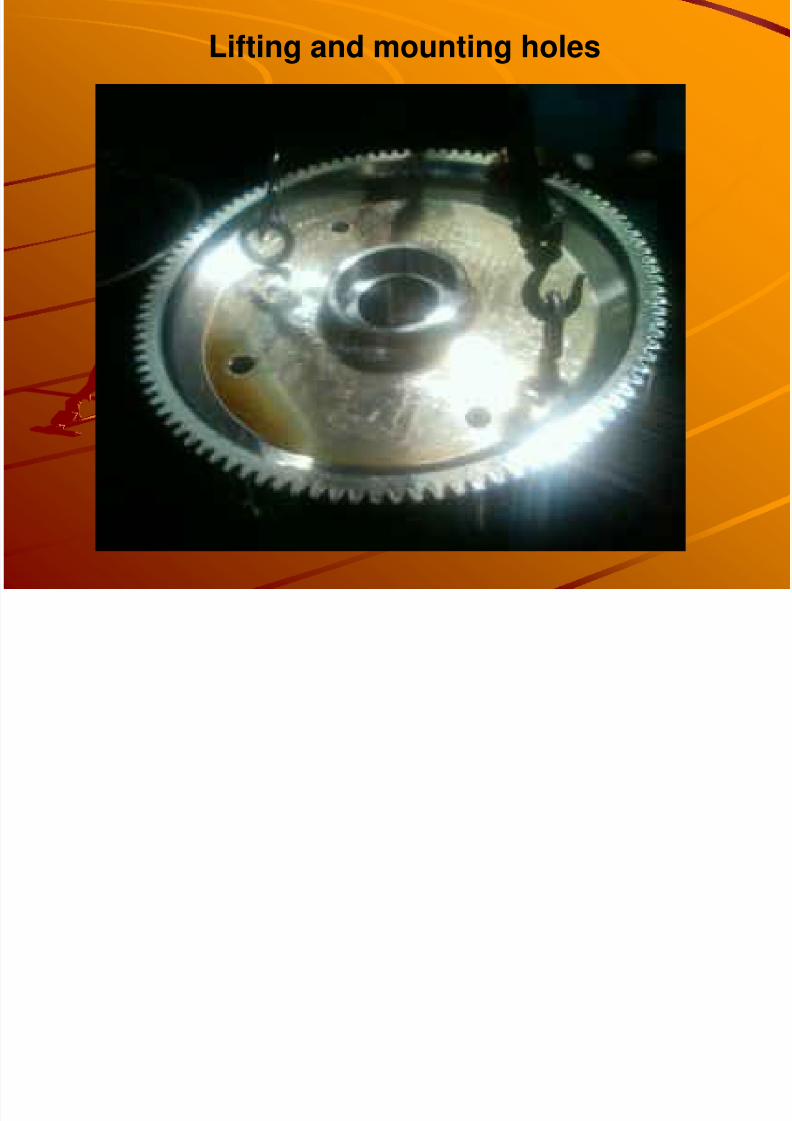
Lifting & Mounting Holes
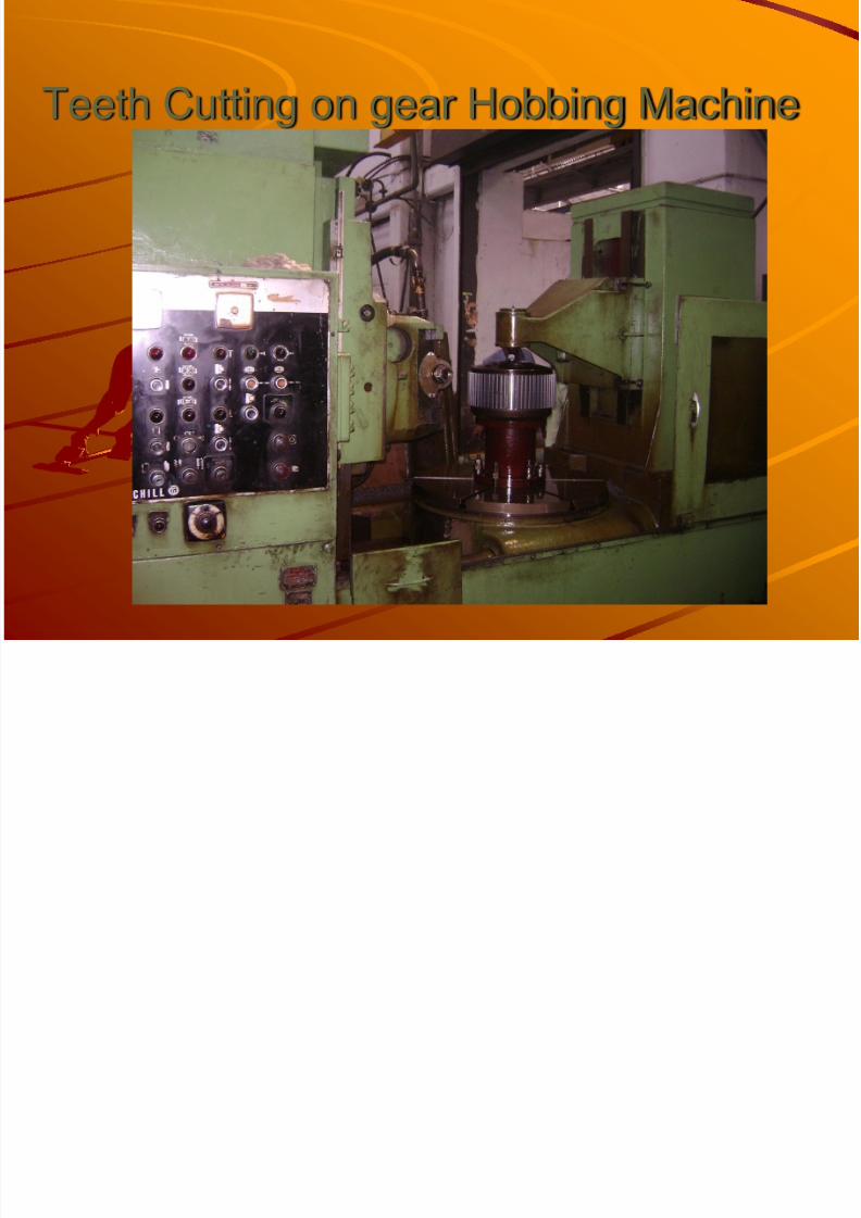
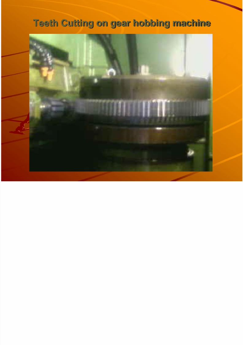
Teeth Cutting on gear hobbing machine.
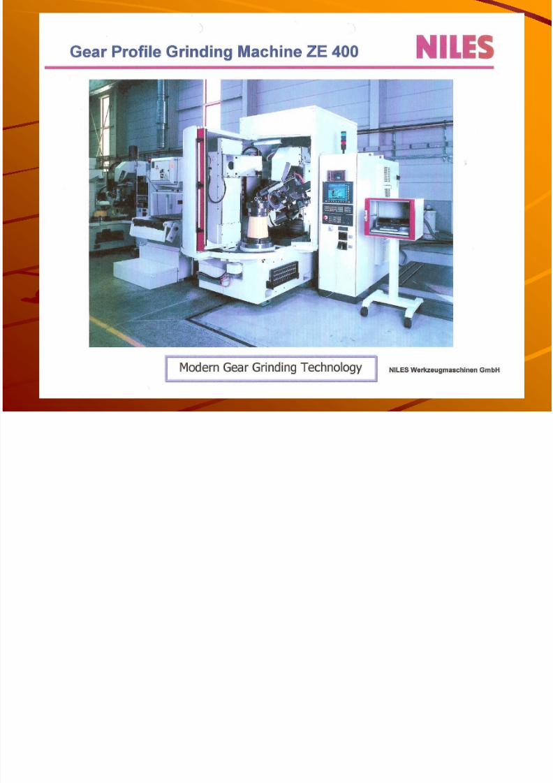
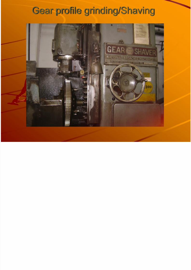
Gear profile grinding/Shaving
Inspection
Broach Key Way
Locking hole
Burr removal
Number Punch
Despatch to HTS for Luborite
8/4/2019 Cam Shaft Gear Presentation
http://slidepdf.com/reader/full/cam-shaft-gear-presentation 9/43
Chuck, Finish OD, Co-bore - CNC VTL
8/4/2019 Cam Shaft Gear Presentation
http://slidepdf.com/reader/full/cam-shaft-gear-presentation 10/43
8/4/2019 Cam Shaft Gear Presentation
http://slidepdf.com/reader/full/cam-shaft-gear-presentation 11/43
Drilling M/C for Lifting & Mounting Holes
8/4/2019 Cam Shaft Gear Presentation
http://slidepdf.com/reader/full/cam-shaft-gear-presentation 12/43
Lifting and mounting holes
8/4/2019 Cam Shaft Gear Presentation
http://slidepdf.com/reader/full/cam-shaft-gear-presentation 13/43
Teeth Cutting on gear Hobbing Machine
8/4/2019 Cam Shaft Gear Presentation
http://slidepdf.com/reader/full/cam-shaft-gear-presentation 14/43
Teeth Cutting on gear hobbing machine
8/4/2019 Cam Shaft Gear Presentation
http://slidepdf.com/reader/full/cam-shaft-gear-presentation 15/43
Gear profile grinding/Shaving
8/4/2019 Cam Shaft Gear Presentation
http://slidepdf.com/reader/full/cam-shaft-gear-presentation 16/43
Lubrite Process in HTS
Lubrite is a rust preventive process.This Process is also known as phosphate Process.Solution of phosphoric acid ratio 1:10.Solution heated up to Temp-85-95 C.
After getting temp. is 85-95 C Camshaft Gear dipped insolution in one hour.After completion of lubrite process camshaft gear sent toENGINE ERECTION SHOP.2 Nos. camshaft gear used in per ALCO Engine.

8/4/2019 Cam Shaft Gear Presentation
http://slidepdf.com/reader/full/cam-shaft-gear-presentation 17/43
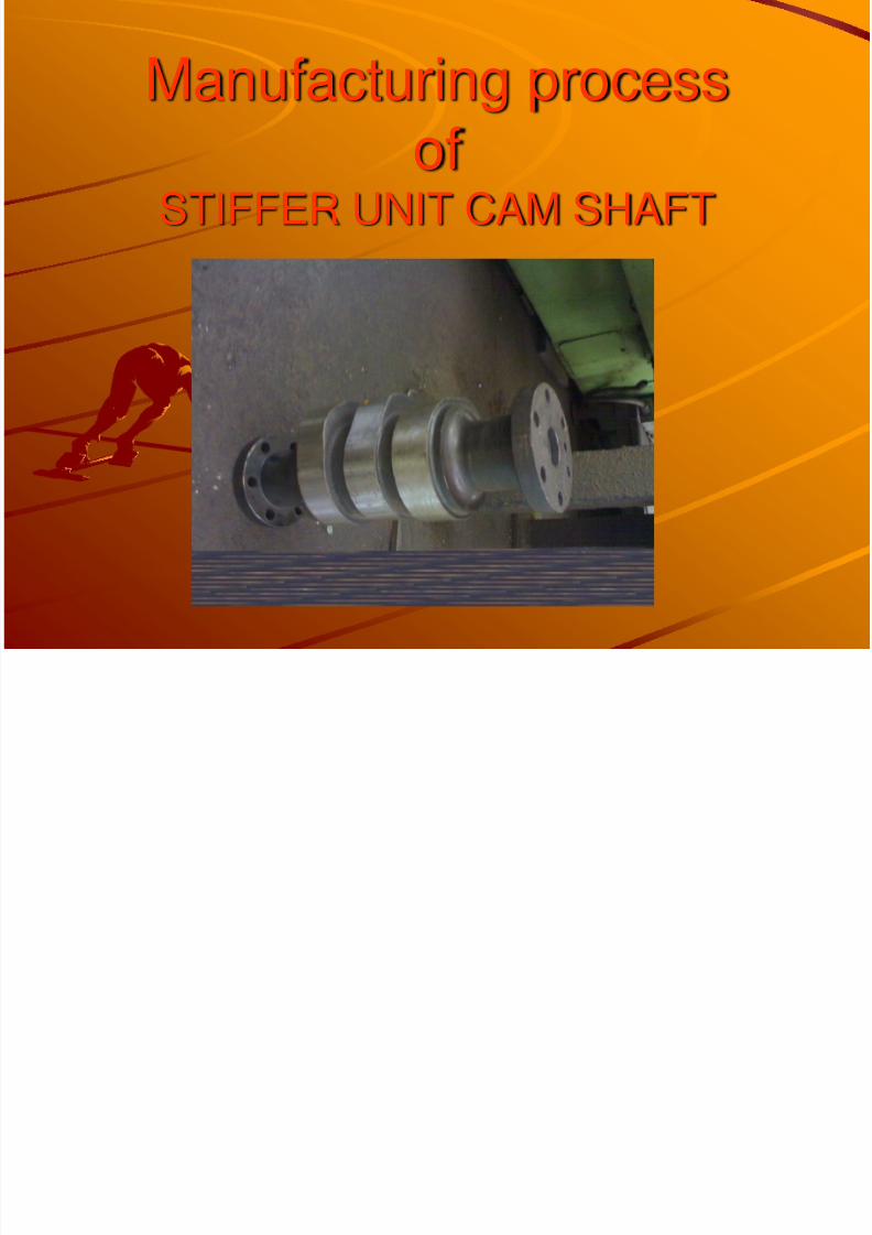
STIFFER UNIT CAMSHAFT
Since 2003
8/4/2019 Cam Shaft Gear Presentation
http://slidepdf.com/reader/full/cam-shaft-gear-presentation 18/43
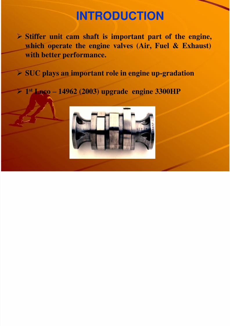
Stiffer unit cam shaft is important part of the engine,which operate the engine valves (Air, Fuel & Exhaust)with better performance.
SUC plays an important role in engine up-gradation
1st Loco – 14962 (2003) upgrade engine 3300HP
INTRODUCTION
8/4/2019 Cam Shaft Gear Presentation
http://slidepdf.com/reader/full/cam-shaft-gear-presentation 19/43
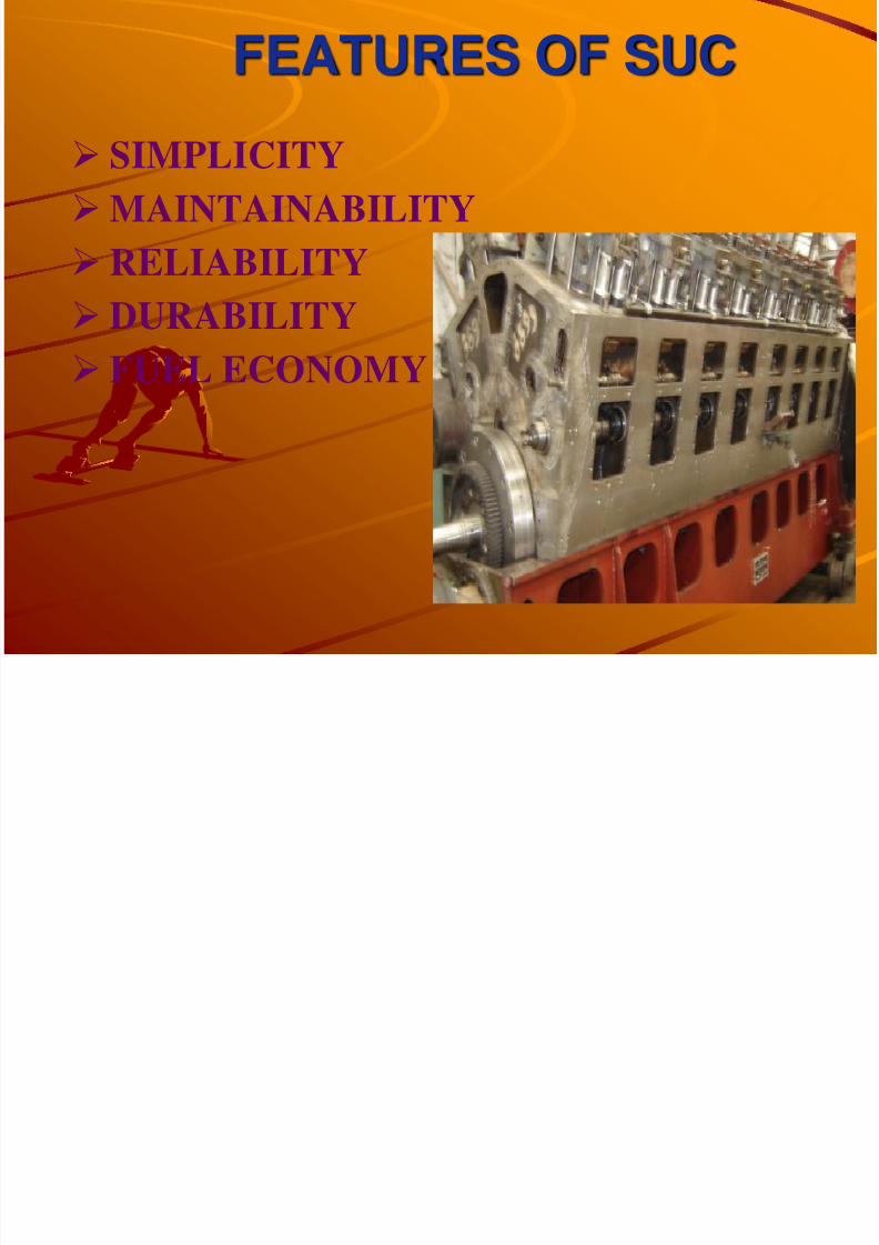
FEATURES OF SUC
SIMPLICITYMAINTAINABILITYRELIABILITY
DURABILITYFUEL ECONOMY
8/4/2019 Cam Shaft Gear Presentation
http://slidepdf.com/reader/full/cam-shaft-gear-presentation 20/43
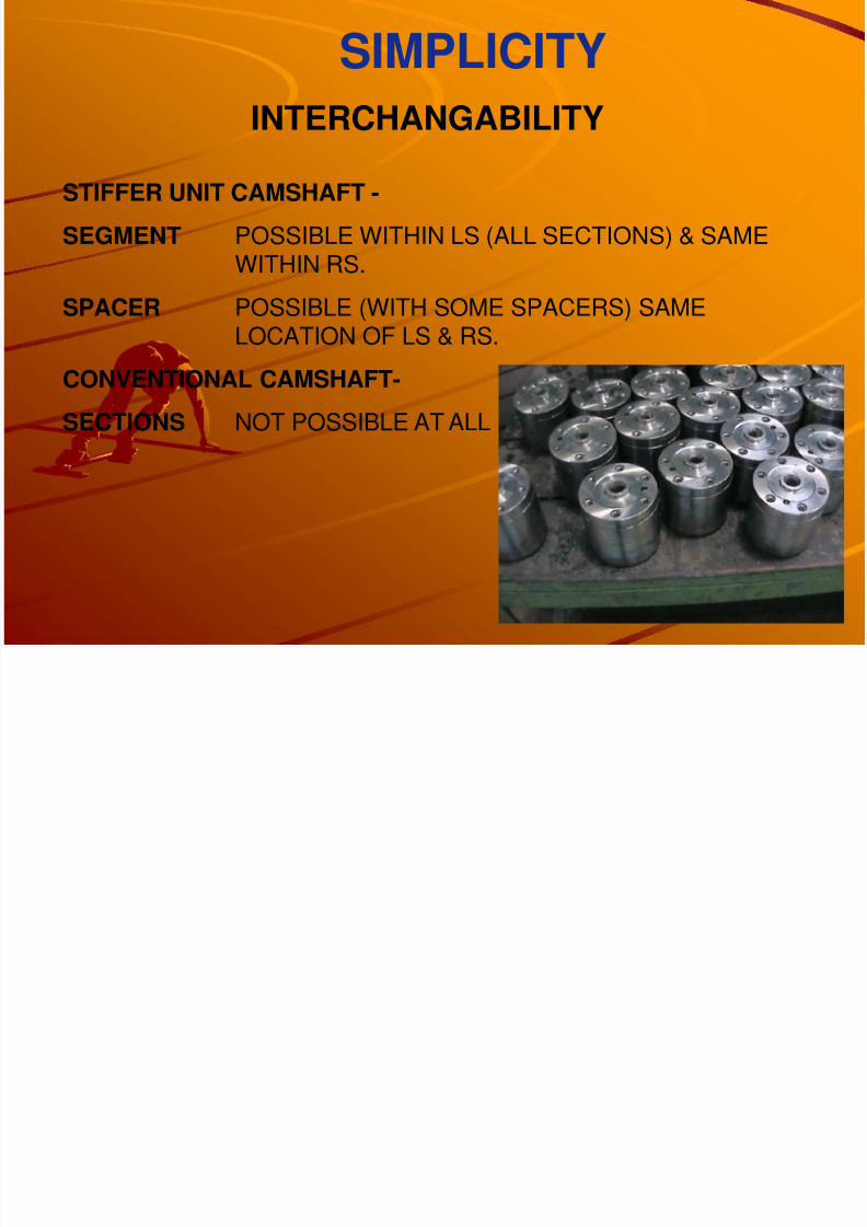
SIMPLICITYINTERCHANGABILITY
STIFFER UNIT CAMSHAFT -
SEGMENT POSSIBLE WITHIN LS (ALL SECTIONS) & SAMEWITHIN RS.
SPACER POSSIBLE (WITH SOME SPACERS) SAMELOCATION OF LS & RS.
CONVENTIONAL CAMSHAFT-
SECTIONS NOT POSSIBLE AT ALL
8/4/2019 Cam Shaft Gear Presentation
http://slidepdf.com/reader/full/cam-shaft-gear-presentation 21/43
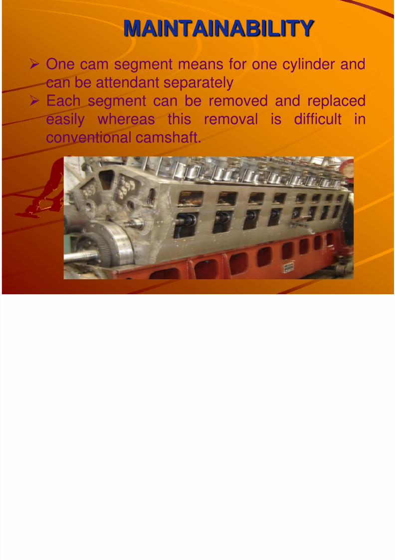
MAINTAINABILITY
One cam segment means for one cylinder andcan be attendant separatelyEach segment can be removed and replacedeasily whereas this removal is difficult in
conventional camshaft.
8/4/2019 Cam Shaft Gear Presentation
http://slidepdf.com/reader/full/cam-shaft-gear-presentation 22/43
RELIABILITY & DURABILITY
Larger dia cam base circle & cam roller canwithstand higher stresses, resulting highercamshaft life and improve the self dampingcapacity.
Lever ratio of cross head 1:1 in comparisonto 1.3:1 and reduce the stress 30%Larger dia of lobes and roller also reducingcontact stresses.
More Stiffness of this camshaft provideresistance against the force of fuel pump andpush rod.27% Higher tortional stiffness.
8/4/2019 Cam Shaft Gear Presentation
http://slidepdf.com/reader/full/cam-shaft-gear-presentation 23/43
FUEL ECONOMY
Improved Fuel cam profile reduce thelagging /delay in fuel injection.Better stiffness reduce the torsional & bending vibration and improve the fuel
efficiency after increasing fuel injectionpressure.Injection start at 22º before TDC instiffer unit camshaft reduce theinjection period.Higher fuel lift improve injectionpressure for fuel efficiency.
8/4/2019 Cam Shaft Gear Presentation
http://slidepdf.com/reader/full/cam-shaft-gear-presentation 24/43
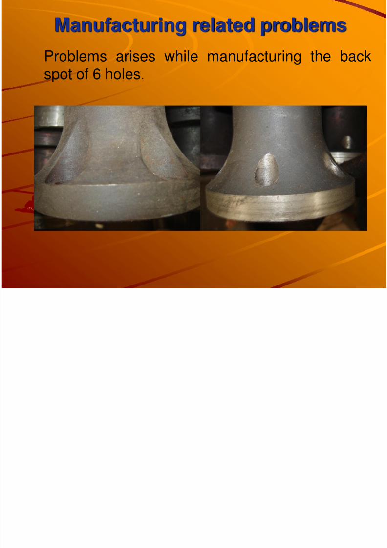
Manufacturing related problemsProblems arises while manufacturing the backspot of 6 holes .
8/4/2019 Cam Shaft Gear Presentation
http://slidepdf.com/reader/full/cam-shaft-gear-presentation 25/43
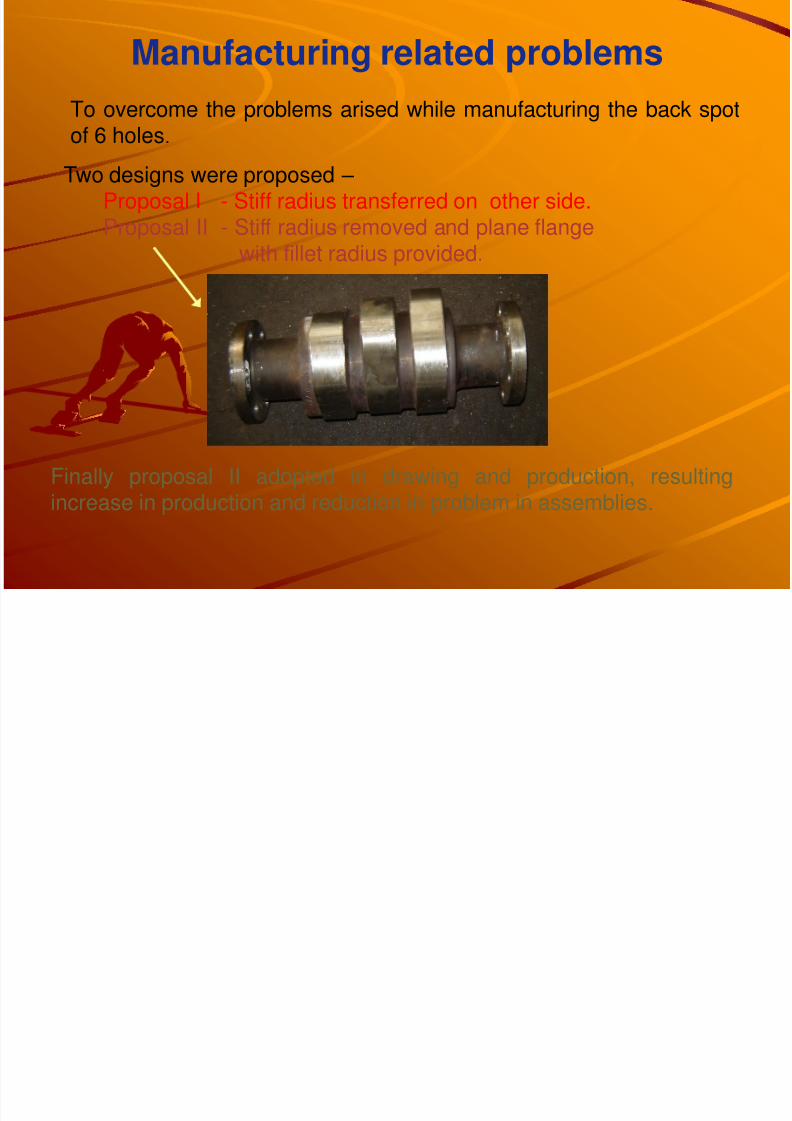
Two designs were proposed – Proposal I - Stiff radius transferred on other side. Proposal II - Stiff radius removed and plane flange
with fillet radius provided.
Manufacturing related problemsTo overcome the problems arised while manufacturing the back spot
of 6 holes .
Finally proposal II adopted in drawing and production, resultingincrease in production and reduction in problem in assemblies.
8/4/2019 Cam Shaft Gear Presentation
http://slidepdf.com/reader/full/cam-shaft-gear-presentation 26/43
Manufacturing process
of STIFFER UNIT CAM SHAFT
8/4/2019 Cam Shaft Gear Presentation
http://slidepdf.com/reader/full/cam-shaft-gear-presentation 27/43
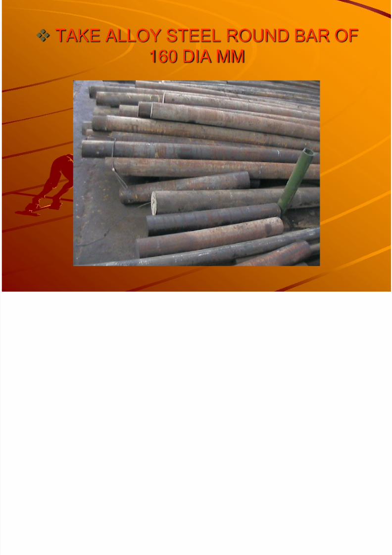
TAKE ALLOY STEEL ROUND BAR OF160 DIA MM
8/4/2019 Cam Shaft Gear Presentation
http://slidepdf.com/reader/full/cam-shaft-gear-presentation 28/43
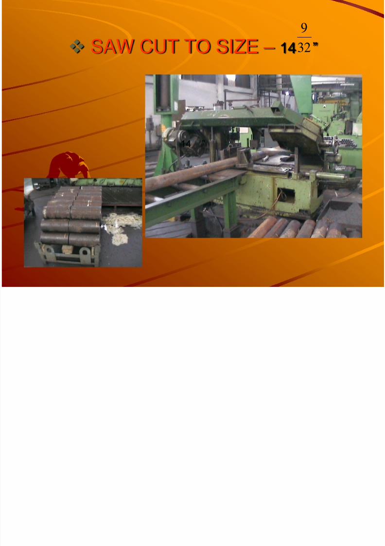
SAW CUT TO SIZE – 14 ” 32
9
14 ”
8/4/2019 Cam Shaft Gear Presentation
http://slidepdf.com/reader/full/cam-shaft-gear-presentation 29/43
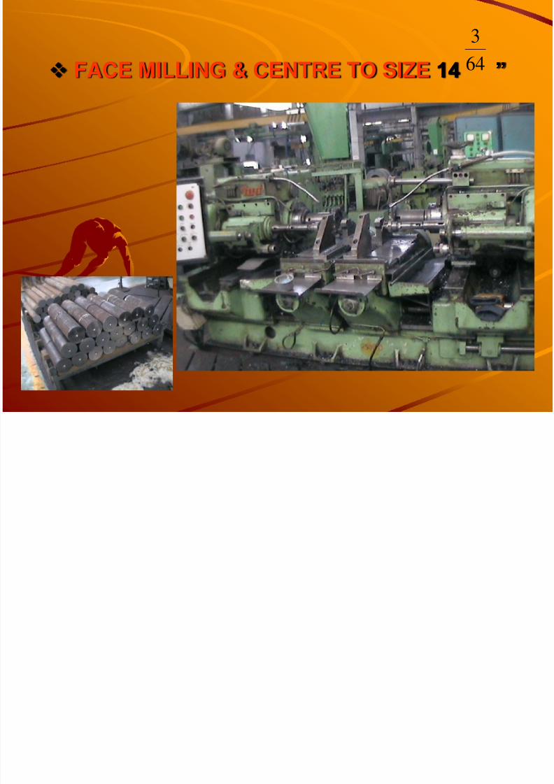
FACE MILLING & CENTRE TO SIZE 14 ” 64
3
8/4/2019 Cam Shaft Gear Presentation
http://slidepdf.com/reader/full/cam-shaft-gear-presentation 30/43
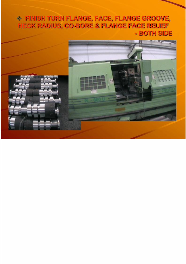
FINISH TURN FLANGE, FACE, FLANGE GROOVE,NECK RADIUS, CO-BORE & FLANGE FACE RELIEF
- BOTH SIDE

8/4/2019 Cam Shaft Gear Presentation
http://slidepdf.com/reader/full/cam-shaft-gear-presentation 31/43
GUN DRILL SIZE ” HOLE THROUGH 4
3

8/4/2019 Cam Shaft Gear Presentation
http://slidepdf.com/reader/full/cam-shaft-gear-presentation 32/43
PUNCH NUMBRE FOR IDENTIFICATION
GRIND BOTH SIDE FACE TO
MAINTAIN TOTAL LENGTH
13.908-13.910 ”
8/4/2019 Cam Shaft Gear Presentation
http://slidepdf.com/reader/full/cam-shaft-gear-presentation 33/43
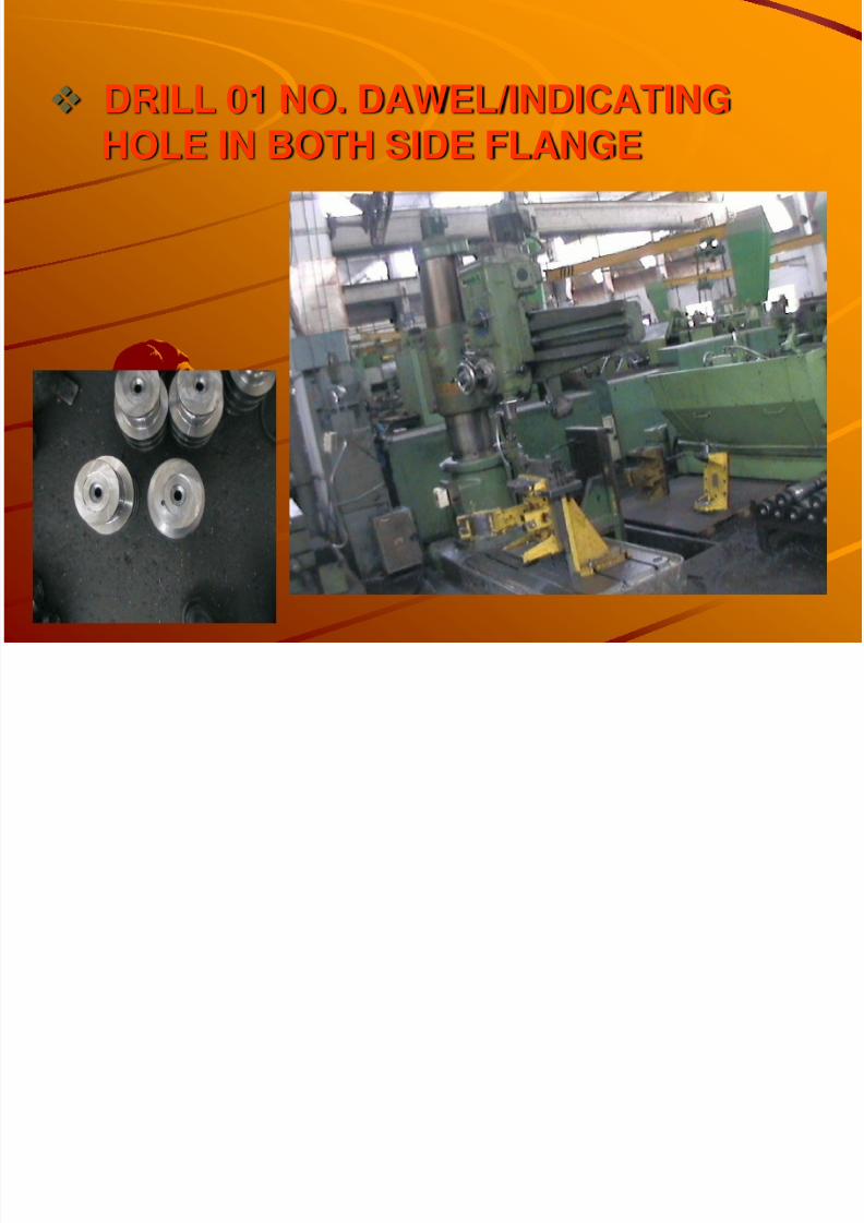
DRILL 01 NO. DAWEL/INDICATING
HOLE IN BOTH SIDE FLANGE
8/4/2019 Cam Shaft Gear Presentation
http://slidepdf.com/reader/full/cam-shaft-gear-presentation 34/43
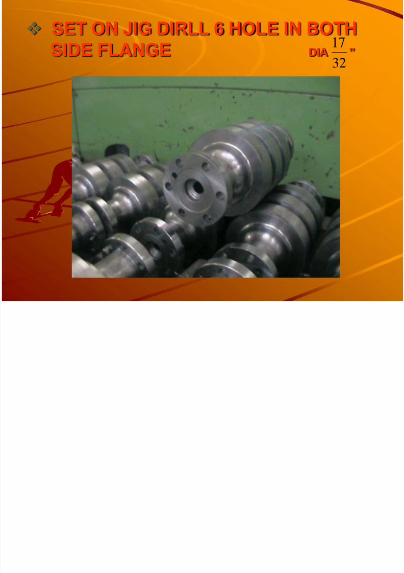
SET ON JIG DIRLL 6 HOLE IN BOTHSIDE FLANGE DIA ”
32
17
8/4/2019 Cam Shaft Gear Presentation
http://slidepdf.com/reader/full/cam-shaft-gear-presentation 35/43
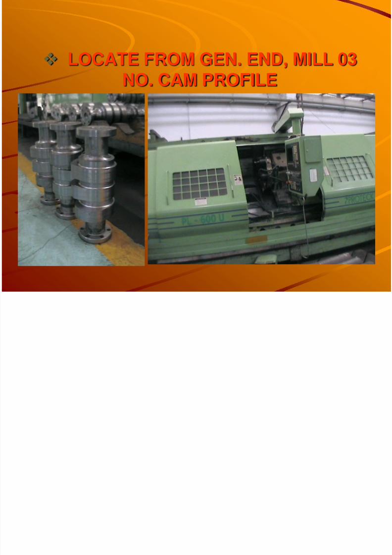
LOCATE FROM GEN. END, MILL 03NO. CAM PROFILE

8/4/2019 Cam Shaft Gear Presentation
http://slidepdf.com/reader/full/cam-shaft-gear-presentation 36/43
REMOVE SHARP EDGES BYROTARY
SEND TO HTS FOR HEATTREATMENT

8/4/2019 Cam Shaft Gear Presentation
http://slidepdf.com/reader/full/cam-shaft-gear-presentation 37/43
STRESS RELIEFHEAT THE JOB UPTO 450 0C & HOLD4 HOURS AT THIS TEMP. THEN COLLIN THE FURNACE AT ROOM TEMP.
8/4/2019 Cam Shaft Gear Presentation
http://slidepdf.com/reader/full/cam-shaft-gear-presentation 38/43
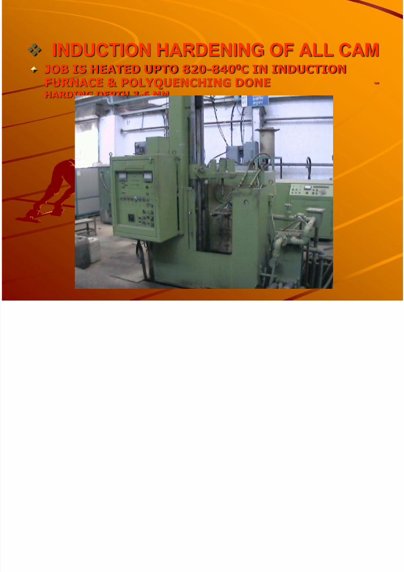
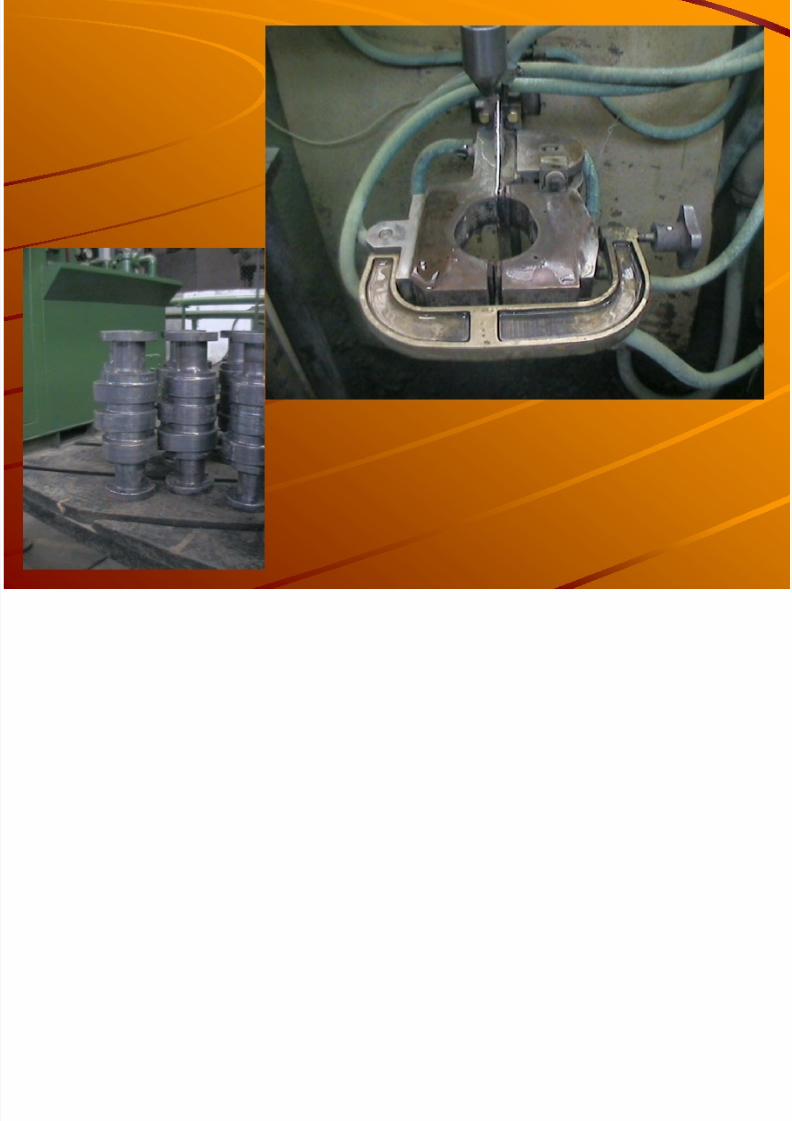
INDUCTION HARDENING OF ALL CAMJOB IS HEATED UPTO 820-840
0
C IN INDUCTIONFURNACE & POLYQUENCHING DONE -HARDING DEPTH 3-6 MM.
8/4/2019 Cam Shaft Gear Presentation
http://slidepdf.com/reader/full/cam-shaft-gear-presentation 39/43
8/4/2019 Cam Shaft Gear Presentation
http://slidepdf.com/reader/full/cam-shaft-gear-presentation 40/43
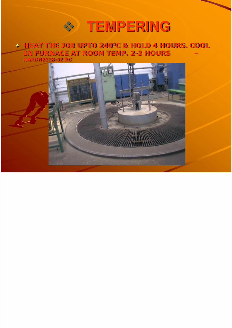
TEMPERINGHEAT THE JOB UPTO 240 0 C & HOLD 4 HOURS. COOLIN FURNACE AT ROOM TEMP. 2-3 HOURS -HARDNES58-62 RC
SEND TO LMS
8/4/2019 Cam Shaft Gear Presentation
http://slidepdf.com/reader/full/cam-shaft-gear-presentation 41/43
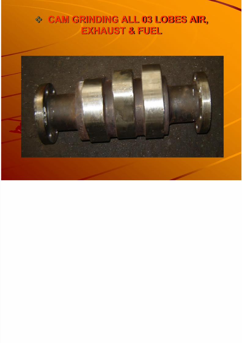
CAM GRINDING ALL 03 LOBES AIR,EXHAUST & FUEL

8/4/2019 Cam Shaft Gear Presentation
http://slidepdf.com/reader/full/cam-shaft-gear-presentation 42/43
REMOVE BURRS FROM ALL CAM
EDGESMAGNAFLUX TEST & DE-MAGNETISEBUFING ON OPENING FLANK OF
FUEL CAMFINAL INSPECTION & HARDEN TESTAPPLY RUST PREVENTIVE
SEND TO SUB ASSEMBLE SHOP

8/4/2019 Cam Shaft Gear Presentation
http://slidepdf.com/reader/full/cam-shaft-gear-presentation 43/43