Embed Size (px)
Citation preview

*6050201848*
This document consists of 12 printed pages.
DC (LK/FC) 148532/2© UCLES 2018 [Turn over
Cambridge International ExaminationsCambridge Ordinary Level
PHYSICS 5054/42Paper 4 Alternative to Practical May/June 2018 1 hourCandidates answer on the Question Paper.No Additional Materials are required.
READ THESE INSTRUCTIONS FIRST
Write your Centre number, candidate number and name on all the work you hand in.Write in dark blue or black pen.You may use an HB pencil for any diagrams or graphs.Do not use staples, paper clips, glue or correction fluid.DO NOT WRITE IN ANY BARCODES.
Answer all questions.
Electronic calculators may be used.You may lose marks if you do not show your working or if you do not use appropriate units.
At the end of the examination, fasten all your work securely together.The number of marks is given in brackets [ ] at the end of each question or part question.
2
5054/42/M/J/18© UCLES 2018
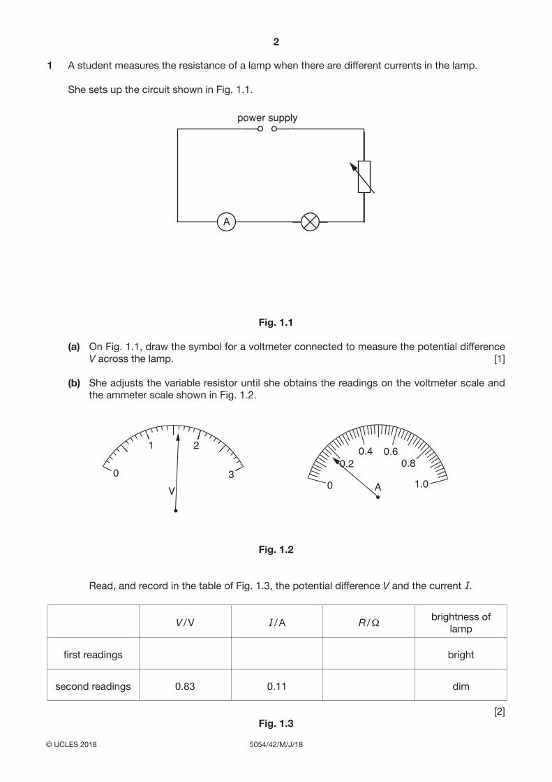
1 A student measures the resistance of a lamp when there are different currents in the lamp.
She sets up the circuit shown in Fig. 1.1.
A
power supply
Fig. 1.1
(a) On Fig. 1.1, draw the symbol for a voltmeter connected to measure the potential difference V across the lamp. [1]
(b) She adjusts the variable resistor until she obtains the readings on the voltmeter scale and the ammeter scale shown in Fig. 1.2.
V0
1 2
30
0.20.4 0.6
0.8
1.0A
Fig. 1.2
Read, and record in the table of Fig. 1.3, the potential difference V and the current I.
V / V I / A R / Ω brightness of lamp
first readings bright
second readings 0.83 0.11 dim
[2]Fig. 1.3

3
5054/42/M/J/18© UCLES 2018 [Turn over
(c) The student adjusts the variable resistor and measures the new values of V and I. Her values are shown in the table of Fig. 1.3. The lamp is dimmer.
Use the equation
R = VI
to calculate the resistance R of the lamp for both settings of the variable resistor.
Record your answers in the table to an appropriate number of significant figures.
[1]
(d) The student thinks that because the same lamp is used throughout the experiment, its resistance is constant.
State whether the student’s results confirm this. Justify your answer by referring to the results.
...................................................................................................................................................
...................................................................................................................................................
............................................................................................................................................... [1]
(e) Another student says that the resistance of a lamp filament increases when it gets hot.
State, giving a reason, whether the observations confirm this.
...................................................................................................................................................
...................................................................................................................................................
............................................................................................................................................... [1]

4
5054/42/M/J/18© UCLES 2018
2 A student investigates the reflection of light by a plane mirror.
• She places the mirror vertically on a sheet of paper.• She uses a pencil to mark the position of the plane mirror with a straight line and
labels the line XY.• She removes the mirror and draws a normal at the centre of the line, and labels the
normal AC.• She labels the point where the normal crosses the mirror with the letter B.
The sheet of paper is shown in Fig. 2.1.
A
C
E
P4
P3
X YB
Fig. 2.1
5
5054/42/M/J/18© UCLES 2018 [Turn over
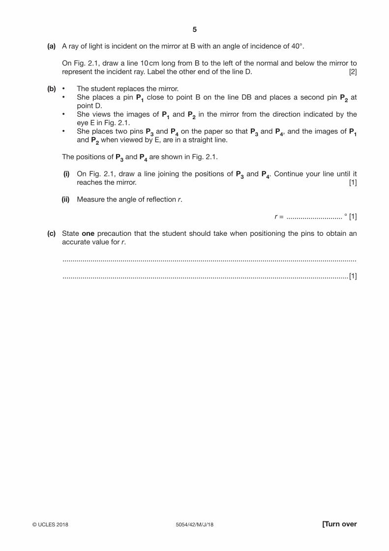
(a) A ray of light is incident on the mirror at B with an angle of incidence of 40°.
On Fig. 2.1, draw a line 10 cm long from B to the left of the normal and below the mirror to represent the incident ray. Label the other end of the line D. [2]
(b) • The student replaces the mirror.• She places a pin P1 close to point B on the line DB and places a second pin P2 at
point D.• She views the images of P1 and P2 in the mirror from the direction indicated by the
eye E in Fig. 2.1.• She places two pins P3 and P4 on the paper so that P3 and P4, and the images of P1
and P2 when viewed by E, are in a straight line.
The positions of P3 and P4 are shown in Fig. 2.1.
(i) On Fig. 2.1, draw a line joining the positions of P3 and P4. Continue your line until it reaches the mirror. [1]
(ii) Measure the angle of reflection r.
r = ............................ ° [1]
(c) State one precaution that the student should take when positioning the pins to obtain an accurate value for r.
...................................................................................................................................................
............................................................................................................................................... [1]

6
5054/42/M/J/18© UCLES 2018
3 A student measures the least pressure that a rectangular wooden block exerts on a table.
• He places the wooden block on a sheet of paper, with its largest surface touching the paper.
• He uses a pencil to draw the outline of the wooden block on the paper.
Fig. 3.1 shows the outline of the block drawn on the paper.
wooden block
Fig. 3.1 (view from above)
(a) Take measurements from the block to the nearest 0.1 cm and calculate the area A of its largest surface.
length = .......................................................
width = .......................................................
A = ....................................................... cm2 [2]

7
5054/42/M/J/18© UCLES 2018 [Turn over
(b) The student finds the weight W of the block with a newton meter, as shown in Fig. 3.2.
N0
1.0
newton meter
wooden block
Fig. 3.2
Write down the weight W of the block.
W = ...................................................... N [1]
(c) Use the equation
p = WA
to calculate the pressure p due to the weight of the block on the table.
p = .............................................. N / cm2 [1]

8
5054/42/M/J/18© UCLES 2018
(d) Another student says that the actual pressure due to the weight of the block on the table is greater than the value calculated in (c).
Suggest one practical reason for this.
...................................................................................................................................................
............................................................................................................................................... [1]
9
5054/42/M/J/18© UCLES 2018 [Turn over
4 A student measures the density of copper using a balancing method.
• She sets up the apparatus as shown in Fig. 4.1.
coppercylinder r1
r2
x y mass M
90
pivot
metrerule
0 cm60
100 cm
Fig. 4.1
• She places a pivot under the 60.0 cm mark of the metre rule. The position of the pivot is not changed during the experiment.
• She places a 150 g mass M on the rule so that its centre is at the 90.0 cm mark of the rule, as shown in Fig. 4.1.
• She places a copper cylinder on the rule and adjusts its position until the rule is just balanced.
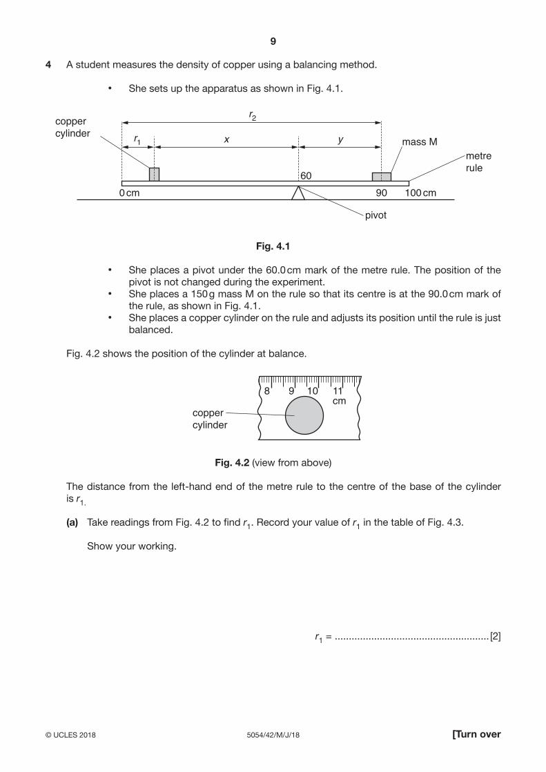
Fig. 4.2 shows the position of the cylinder at balance.
8 9 10 11cm
coppercylinder
Fig. 4.2 (view from above)
The distance from the left-hand end of the metre rule to the centre of the base of the cylinder is r1.
(a) Take readings from Fig. 4.2 to find r1. Record your value of r1 in the table of Fig. 4.3.
Show your working.
r1 = ....................................................... [2]

10
5054/42/M/J/18© UCLES 2018
(b) The student repeats the procedure by moving mass M and placing its centre on the 85.0, 80.0, 75.0 and 70.0 cm marks of the metre rule. Her results are shown in the table of Fig. 4.3.
The distance from the left-hand end of the metre rule to the centre of mass M is r2.
r1 / cm r2 / cmdistance of centre of
the cylinder from pivotx = (60 – r1) / cm
distance of centre of mass M from pivot
y = (r2 – 60) / cm90.0
20.2 85.0 37.8 25.031.9 80.0 28.1 20.041.8 75.0 16.4 15.055.3 70.0 4.7 10.0
Fig. 4.3
00
Fig. 4.4

11
5054/42/M/J/18© UCLES 2018 [Turn over
(i) Record, in the table of Fig. 4.3, the missing values of x and y. [1]
(ii) On the grid in Fig. 4.4, plot a graph of y (y-axis) against x (x-axis). Start your axes from the origin (0,0). Draw the straight line of best fit. [4]
(iii) Determine the gradient of your line.
Show your working and indicate on your graph the values you choose.
gradient of line = ....................................................... [2]
(iv) The mass m, in grams, of the copper cylinder is given by the equation
m = 150 × gradient.
Use this equation to calculate m to the nearest gram.
m = ....................................................... g [1]
Question 4 is continued on page 12.
Permission to reproduce items where third-party owned material protected by copyright is included has been sought and cleared where possible. Every reasonable effort has been made by the publisher (UCLES) to trace copyright holders, but if any items requiring clearance have unwittingly been included, the publisher will be pleased to make amends at the earliest possible opportunity.
To avoid the issue of disclosure of answer-related information to candidates, all copyright acknowledgements are reproduced online in the Cambridge International Examinations Copyright Acknowledgements Booklet. This is produced for each series of examinations and is freely available to download at www.cie.org.uk after the live examination series.
Cambridge International Examinations is part of the Cambridge Assessment Group. Cambridge Assessment is the brand name of University of Cambridge Local Examinations Syndicate (UCLES), which is itself a department of the University of Cambridge.

12
5054/42/M/J/18© UCLES 2018
(c) The student uses a measuring cylinder to find the volume V of the copper cylinder.
• She pours 50 cm3 of water into the measuring cylinder.• She lowers the copper cylinder gently into the measuring cylinder.
Fig. 4.5 shows the measuring cylinder containing the copper cylinder.
10
20
30
40
50
60
70
80
90
100
measuring cylinder
copper cylinder
water
cm3
Fig. 4.5
Use the information in Fig. 4.5 to calculate the volume V of the copper cylinder.
V = ................................................... cm3 [2]
(d) Calculate the density ρ of copper using your answers to (b)(iv) and (c) and the equation
ρ = mV
.
ρ = .............................................. g / cm3 [1]
(e) The value for the density of copper obtained in (d) differs slightly from the correct value.
State one practical reason for this difference.
...................................................................................................................................................
............................................................................................................................................... [1]