Embed Size (px)
Citation preview

TECHNICALSCambridge
CAMBRIDGE TECHNICALS IN ENGINEERINGLEVEL 3 UNIT 17 – COMPUTER AIDED MANUFACTURING (CAM)
DELIVERY GUIDEVersion 1
OC
R LEVEL 3 CA
MBRID
GE TEC
HN
ICA
LS IN EN
GIN
EERING
CO
MPU
TER AID
ED M
AN
UFA
CTU
RING
(CA
M) 2
CONTENTS
Introduction 3
Related Activities 4
Key Terms 5
Misconceptions 8
Suggested Activities:
Learning Outcome (LO1) 10
Learning Outcome (LO2) 12
Learning Outcome (LO3) 14
Learning Outcome (LO4) 15

OC
R LE
VEL
3 C
AM
BRID
GE
TEC
HN
ICA
LS IN
EN
GIN
EERI
NG
CO
MPU
TER
AID
ED M
AN
UFA
CTU
RIN
G (C
AM
)
3 3
INTRODUCTIONThis Delivery Guide has been developed to provide practitioners with a variety of creative and practical ideas to support the delivery of this qualification. The Guide is a collection of lesson ideas with associated activities, which you may find helpful as you plan your lessons.
OCR has collaborated with current practitioners to ensure that the ideas put forward in this Delivery Guide are practical, realistic and dynamic. The Guide is structured by learning outcome so you can see how each activity helps you cover the requirements of this unit.
We appreciate that practitioners are knowledgeable in relation to what works for them and their learners. Therefore, the resources we have produced should not restrict or impact on practitioners’ creativity to deliver excellent learning opportunities.
Whether you are an experienced practitioner or new to the sector, we hope you find something in this guide which will help you to deliver excellent learning opportunities.
If you have any feedback on this Delivery Guide or suggestions for other resources you would like OCR to develop, please email [email protected].
Unit aimMany companies which make products are reliant on computer systems to run the manufacturing processes involved. This is known as Computer Aided Manufacturing (CAM).
The aim of this unit is for learners to understand how CAM systems are used within manufacturing and be able to program and use Computer Numerical Control (CNC) machines to produce components.
They will also learn to produce components using additive manufacturing techniques.
Computer aided manufacturing (CAM)
LO1 Understand how computers are used in manufacturing systems
LO2 Be able to produce CNC programs for the manufacture of components
LO3 Be able to set-up and operate a CNC machine to produce components
LO4 Be able to produce components using additive manufacturing techniques
Opportunities for English and maths skills developmentWe believe that being able to make good progress in English and maths is essential to learners in both of these contexts and on a range of learning programmes. To help you enable your learners to progress in these subjects, we have signposted opportunities for English and maths skills practice within this resource. These suggestions are for guidance only. They are not designed to replace your own subject knowledge and expertise in deciding what is most appropriate for your learners.
English Maths
Please note
The activities suggested in this Delivery Guide MUST NOT be used for assessment purposes. The timings for the suggested activities in this Delivery Guide DO NOT relate to the Guided Learning Hours (GLHs) for each unit.
Assessment guidance can be found within the Unit document available from www.ocr.org.uk. The latest version of this Delivery Guide can be downloaded from the OCR website.

OC
R LEVEL 3 CA
MBRID
GE TEC
HN
ICA
LS IN EN
GIN
EERING
CO
MPU
TER AID
ED M
AN
UFA
CTU
RING
(CA
M) 4
This unit (Unit 17) Title of suggested activity Other units/LOs
LO2Use of CAD geometry and exporting data Unit 10 Computer Aided Design
(CAD)LO4 Understand the use of simulation tools within CAD systems
LO4Production of 3D components from CAD data using additive manufacturing
Unit 10 Computer Aided Design (CAD)
LO4 Understand the use of simulation tools within CAD systems
The Suggested Activities in this Delivery Guide listed below have also been related to other Cambridge Technicals in Engineering units/Learning Outcomes (LOs). This could help with delivery planning and enable learners to cover multiple parts of units.
RELATED ACTIVITIES

OC
R LE
VEL
3 C
AM
BRID
GE
TEC
HN
ICA
LS IN
EN
GIN
EERI
NG
CO
MPU
TER
AID
ED M
AN
UFA
CTU
RIN
G (C
AM
)
5
KEY TERMSUNIT 17 – COMPUTER AIDED MANUFACTURING (CAM)
Explanations of the key terms used within this unit, in the context of this unit
Key term Explanation
2½D (2.5D) CAD/CAM using 2D graphics but manufactured using some depth of cut information (Z value stays constant for duration of cut).
3MF A new AM format being developed by Microsoft and partners to carry all additional information such as colour and texture.
Absolute coordinates The location of a point in terms of distances and/or angles from a fixed origin.
AM (additive manufacture)
Various processes (including 3D printing and rapid prototyping) used to make a 3D object in which successive layers of material are laid down under computer control. Contrasts with CNC machining which is subtractive manufacture. See: https://en.wikipedia.org/wiki/3D_printing
Arc A curve segment defined by a start angle, end angle, and a constant radius.
Array A rectangular or circular pattern of graphical objects.
Ascii (American Standard Code for Information Interchange)
An industry standard character code that is widely used for information interchange among data processing systems, communications systems, and associated equipment.
Assembly Two or more parts or components put together to create a product.
Associative geometry A system that lets you place graphic elements based on a relationship (e.g. parallel) with existing graphic elements. The relationship is maintained when the existing graphic element is manipulated.
Axis A general direction of relative motion between a cutting tool and the workpiece.
Ball end mill Milling tool commonly used for creating complex surface machining operations. End of tool is rounded so that the radius on tool end equals half of tool diameter.
Batch production Manufacture where small numbers of identical items are made.
CAE (computer-aided engineering)
The application of computer software in engineering to evaluate components and assemblies. It encompasses simulation, validation, and optimization of products and manufacturing tools. The primary application of CAE, used in civil, mechanical, aerospace, and electronic engineering, takes the form of FEA (Finite element analysis) alongside computer-aided design.
Canned cycle Term commonly used to refer to pre-programmed machining cycles on a particular machine tool. Examples include drilling, boring, and tapping.
Cartesian coordinate system
A rectangular coordinate system consisting of three mutually perpendicular axes: the x axis, the y axis, and the z axis.
CIM (computer-integrated manufacturing)
Automated use of computer and digital technology to completely integrate all manufacturing processes with engineering design.
Circular interpolation Method of instructing a machine tool to follow a circular path, instead of programming many straight line moves around an arc.
Climb cut Type of milling where cutting forces are directed down into the workpiece. Opposite of conventional cutting. Determined by combination of spindle rotation direction and tool feed direction.
Closed-loop system A system that works automatically and does not contain feedback.
OC
R LEVEL 3 CA
MBRID
GE TEC
HN
ICA
LS IN EN
GIN
EERING
CO
MPU
TER AID
ED M
AN
UFA
CTU
RING
(CA
M) 6
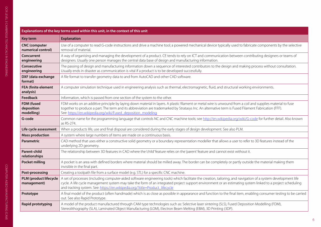
Explanations of the key terms used within this unit, in the context of this unit
Key term Explanation
CNC (computer numerical control)
Use of a computer to read G-code instructions and drive a machine tool; a powered mechanical device typically used to fabricate components by the selective removal of material.
Concurrent engineering
A way of organising and managing the development of a product. CE tends to rely on ICT and communication between contributing designers or teams of designers. Usually one person manages the central data base of design and manufacturing information.
Consecutive engineering
The passing of design and manufacturing information down a sequence of interested contributors to the design and making process without consultation. Usually ends in disaster as communication is vital if a product is to be developed successfully.
DXF (data exchange format)
A file format to transfer geometry data to and from AutoCAD and other CAD software.
FEA (finite element analysis)
A computer simulation technique used in engineering analysis such as thermal, electromagnetic, fluid, and structural working environments.
Feedback Information, which is passed from one section of the system to the other.
FDM (fused deposition modelling)
FDM works on an additive principle by laying down material in layers. A plastic filament or metal wire is unwound from a coil and supplies material to fuse together to produce a part. The term and its abbreviation are trademarked by Stratasys Inc. An alternative term is Fused Filament Fabrication (FFF). See: https://en.wikipedia.org/wiki/Fused_deposition_modeling
G-code Common name for the programming language that controls NC and CNC machine tools; see http://en.wikipedia.org/wiki/G-code for further detail. Also known as RS-274.
Life cycle assessment When a products life, use and final disposal are considered during the early stages of design development. See also PLM.
Mass production A system where large numbers of items are made on a continuous basis.
Parametric CAD method that uses either a constructive solid geometry or a boundary representation modeller that allows a user to refer to 3D features instead of the underlying 2D geometry.
Parent-child relationships
The relationship between 3D features in CAD where the ‘child’ feature relies on the ‘parent’ feature and cannot exist without it.
Pocket milling A pocket is an area with defined borders where material should be milled away. The border can be completely or partly outside the material making them invisible in the final part.
Post-processing Creating a toolpath file from a surface model (e.g. STL) for a specific CNC machine.
PLM (product lifecycle management)
A set of processes (including computer-aided software engineering tools) which facilitate the creation, tailoring, and navigation of a system development life cycle. A life cycle management system may take the form of an integrated project support environment or an estimating system linked to a project scheduling and tracking system. See: https://en.wikipedia.org/?title=Product_lifecycle
Prototype A final model of the product (often handmade) which is as close as possible in appearance and function to the final item, enabling consumer testing to be carried out. See also Rapid Prototype.
Rapid prototyping A model of the product manufactured through CAM type technologies such as: Selective laser sintering (SLS), Fused Deposition Modelling (FDM), Stereolithography (SLA), Laminated Object Manufacturing (LOM), Electron Beam Melting (EBM), 3D Printing (3DP).

OC
R LE
VEL
3 C
AM
BRID
GE
TEC
HN
ICA
LS IN
EN
GIN
EERI
NG
CO
MPU
TER
AID
ED M
AN
UFA
CTU
RIN
G (C
AM
)
7
Explanations of the key terms used within this unit, in the context of this unit
Key term Explanation
Reverse engineering A useful method to create a 3D virtual model of an existing physical part (by manual measurement or computer scanning) for use in 3D CAD, CAM, CAE and other software.
Simulation Modelling a real-life or hypothetical situation on a computer so that it can be studied to see how the system works. By changing variables, predictions may be made about the behaviour of the system.
Spiral cutting Type of milling cut where the tool begins in the geometric centre of the area being machined and spirals its way out to the outside.
STL – stereolithography
A file format widely used for rapid prototyping and computer-aided manufacturing. STL files describe the surface geometry of a three dimensional object as a triangular mesh without any representation of colour, texture or other attributes. Stereolithography is an additive fabrication process utilizing a vat of liquid UV-curable photopolymer ‘resin’ and a UV laser to build parts a layer at a time.
Tool path The 2D or 3D path that the tool follows when machining.
Virtual reality Three dimensional images generated by a computer that give the impression of reality for visual evaluation. The files commonly used are VRML (Virtual Reality Modelling Language) and X3D; the ISO standard XML-based file format.
Waterline machining Slices the model into many horizontal slices and creates a toolpath that traces each one with a constant z value.

OC
R LEVEL 3 CA
MBRID
GE TEC
HN
ICA
LS IN EN
GIN
EERING
CO
MPU
TER AID
ED M
AN
UFA
CTU
RING
(CA
M) 8
Some common misconceptions and guidance on how they could be overcome
What is the misconception? How can this be overcome? Resources which could help
Rapid prototyping is slow The typical desktop 3D printer prints at speeds which are typically in the range of 50–150 mm/sec. This means that the extruder is able to lay down 50–150 mm of molten filament every second. This may sound quite fast, and in fact the movements are rather rapid, but the layer height of the extruded plastic is usually so small that such speed does not translate into rapid fabrication. Compare this with making a prototype by traditional hand making skills and assembly methods and there is a definite advantage in speed. Also the CAD/CAM route has the major advantage of easy modification following evaluation of the prototype.
It all depends on what the prototype is for and whether surface finish is important.
Estimates of manufacturing time will be useful in helping to make decisions about manufacturing methods.
The software that drives 3D printers will give an estimate of the amount of material required and the time needed to manufacture a product. The other variable will be the density of fill material chosen.For example, Ultimaker: https://ultimaker.com/en
With CNC machines the material hardness, machine path and cutting depth will affect the manufacturing speed. For example, Boxford GeoCam gives a range of machining strategies and calculates an approximate machining time: http://www.boxford.co.uk/software/3d-stand-alone-cam/
Additive manufacturing can make any shaped part
In theory any shape could be made, but there are restrictions to overhangs and interior hollows and of course the size of the machine. Certainly, additive manufacture can be used to make shapes that CNC mills and lathes can never make.
The machine software will give you an idea of the possibilities with a part. The following software will analyse and repair the STL file: Mesh Lab (free): http://meshlab.sourceforge.net/ Meshmixer (free): http://www.123dapp.com/meshmixer NetFabb (free basic version): http://www.netfabb.com/education.php
Additive manufacturing can replace production lines
Currently most additive manufacturing processes are too slow for mass production but they are excellent for design development, customisation of parts and ‘just-in-time’. This is best seen in fashion and medical applications where individual parts are needed to fit specific people and situations.
Surgeons use 3D Printing Technology to Perform World’s First Skull Transplant:http://www.medicaldaily.com/breakthrough-surgeons-use-3-d-printing-technology-perform-worlds-first-skull-transplant-273288
Just before the end of November 2013, Mick Ebeling returned home from Sudan’s Nuba Mountains where he set up what is probably the world’s first 3D-printing prosthetic lab and training facility. http://www.notimpossiblelabs.com/#!project-daniel/c1imu
Work begins on the world’s first 3D-printed house. Zero waste, lower transport costs and recyclable materials: 3D printing the future of housebuilding
MISCONCEPTIONS

OC
R LE
VEL
3 C
AM
BRID
GE
TEC
HN
ICA
LS IN
EN
GIN
EERI
NG
CO
MPU
TER
AID
ED M
AN
UFA
CTU
RIN
G (C
AM
)
9
What is the misconception? How can this be overcome? Resources which could help
Why does CAM need simulation? Simulation enables you to visualize exactly how your part will be cut with all your machining operations, before you run it on your CNC-machine. This will allow you to rapidly visualise and improve upon designs without wasting material or breaking tools.• The simulation functions will allow you to set machine travel
limits and detect over travels.
• The simulation will allow you to check for any errors on the part. Including machine, tool and tool-holder collisions.
• You will be able to see the surface finish of the completed part and investigate a range of tool path types.
• The simulated machine can be turned on and off for closer part inspection.
• You can calculate machine cycle times on part programs.
There are a number of simulation programs as part of specific machine software. For example, Boxford’s 3D GeoCam works with a large range of post-processors: http://www.boxford.co.uk/software/3d-stand-alone-cam/
Denford’s Virtual Reality (VR) CNC Milling 5 has a powerful, virtual reality 3D simulation engine. VR CNC Turning is similar for CNC lathes:http://website.denford.ltd.uk/software-menu
OpenSCAM is free open-source software which simulates 3-axis CNC milling or engraving but does not drive real machines: http://openscam.com/
Is exporting of files from CAD automatic?
Export is not automatic as there are choices to be made. STL format is a surface model of the part made up of a triangular mesh. The size of the triangles can be altered before exporting to give the optimal resolution of the part. Another format is VRML (3XD) which used also to carry colour information (e.g. powder based 3D printers). STEP AP214 will save the colours and layers.A new format is being developed by Microsoft and partners (3MF) to carry all additional information such as colour and texture.
http://www.vpl3d.com/stl-file-settings/
The size of the STL mesh affects the size of the file exported; the finer the mesh the larger the file.
Most CAD programs have an optimum STL output setting for a given 3D model as shown in:http://www.redeyeondemand.com/stl-file-format/http://3dprintingsystems.com/export-to-stl/
STL output is good if the model is good
Before printing or cutting a 3D model from an STL file, it must be examined for errors, especially STLs that have been produced by 3D scanning. Examples of errors are surfaces that do not connect, or gaps in the models.
There is software that finds and corrects errors in STL files such as: http://meshlab.sourceforge.net/http://www.123dapp.com/meshmixerhttp://www.netfabb.com/education.php
CNC cutting wastes material Both additive manufacturing and subtractive manufacturing methods have their own advantages which makes them appropriate for different circumstances. By examining what your own goals are for your project, you should be able to choose the appropriate method for production. For parts with complex geometries or intricate designs, additive manufacturing methods can produce far superior results than subtractive methods but subtractive usually gives better surface finish.
For a good summary of the considerations see:https://www.fictiv.com/resources/starter/additive-vs-subtractive-methods
OC
R LEVEL 3 CA
MBRID
GE TEC
HN
ICA
LS IN EN
GIN
EERING
CO
MPU
TER AID
ED M
AN
UFA
CTU
RING
(CA
M) 10
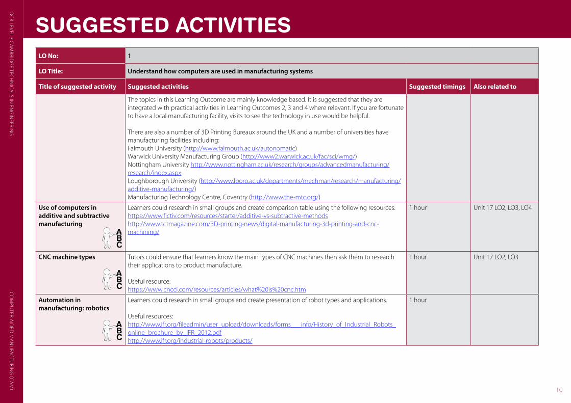
SUGGESTED ACTIVITIESLO No: 1
LO Title: Understand how computers are used in manufacturing systems
Title of suggested activity Suggested activities Suggested timings Also related to
The topics in this Learning Outcome are mainly knowledge based. It is suggested that they are integrated with practical activities in Learning Outcomes 2, 3 and 4 where relevant. If you are fortunate to have a local manufacturing facility, visits to see the technology in use would be helpful.
There are also a number of 3D Printing Bureaux around the UK and a number of universities have manufacturing facilities including: Falmouth University (http://www.falmouth.ac.uk/autonomatic)Warwick University Manufacturing Group (http://www2.warwick.ac.uk/fac/sci/wmg/)Nottingham University http://www.nottingham.ac.uk/research/groups/advancedmanufacturing/research/index.aspxLoughborough University (http://www.lboro.ac.uk/departments/mechman/research/manufacturing/additive-manufacturing/)Manufacturing Technology Centre, Coventry (http://www.the-mtc.org/)
Use of computers in additive and subtractive manufacturing
Learners could research in small groups and create comparison table using the following resources:https://www.fictiv.com/resources/starter/additive-vs-subtractive-methodshttp://www.tctmagazine.com/3D-printing-news/digital-manufacturing-3d-printing-and-cnc-machining/
1 hour Unit 17 LO2, LO3, LO4
CNC machine types Tutors could ensure that learners know the main types of CNC machines then ask them to research their applications to product manufacture.
Useful resource:https://www.cncci.com/resources/articles/what%20is%20cnc.htm
1 hour Unit 17 LO2, LO3
Automation in manufacturing: robotics
Learners could research in small groups and create presentation of robot types and applications.
Useful resources:http://www.ifr.org/fileadmin/user_upload/downloads/forms___info/History_of_Industrial_Robots_online_brochure_by_IFR_2012.pdfhttp://www.ifr.org/industrial-robots/products/
1 hour

OC
R LE
VEL
3 C
AM
BRID
GE
TEC
HN
ICA
LS IN
EN
GIN
EERI
NG
CO
MPU
TER
AID
ED M
AN
UFA
CTU
RIN
G (C
AM
)
11
Title of suggested activity Suggested activities Suggested timings Also related to
Automation in manufacturing: systems and control
Learners, in small groups, could research and create a presentation on ‘the modern manufacturing facility’. Tutors could arrange a visit to a local manufacturing centre.
Useful resource:http://www.raeng.org.uk/publications/reports/an-insight-into-modern-manufacturing-etf-report
1 hour
Computer aided planning: PLM
Learners could take series of products and explain how their lifecycle can be managed. 1 hour
Advantages of using computers in manufacturing
Learners could research and give examples of the benefits such as repeatability, quality, reliability, reduced time to market, responsiveness, customisation.
1 hour Unit 17 LO2, LO3, LO4

OC
R LEVEL 3 CA
MBRID
GE TEC
HN
ICA
LS IN EN
GIN
EERING
CO
MPU
TER AID
ED M
AN
UFA
CTU
RING
(CA
M) 12
LO No: 2
LO Title: Be able to produce CNC programs for the manufacture of components
Title of suggested activity Suggested activities Suggested timings Also related to
G-code programming
See Lesson Element G-code Programming
Learners could use reference pages to see what G-codes do. For example, see: http://www.hsmworks.com/docs/cncbook/en/#Ch05_GMCodes http://gnipsel.com/linuxcnc/reference/page2.html
Learners could watch simulations of existing G-code programs and identify actions.
Learners could plan program for simple 2.5D cutting e.g. one stroke letters, rectangles and circles; including tool offsets.
Useful resource:http://www.helmancnc.com/simple-g-code-example-mill-g-code-programming-for-beginners/
5 hours Unit 17 LO3
On-screen simulation of G-codes
Learners could use programs from G-code programming in simulation software to check the correctness of their coding.
Useful resource:http://cncsimulator.info/
1 hour Unit 17 LO3
Speeds and feeds Learners could calculate speeds and feeds from standard formulae:FR = RPM × T × CLWhere: FR = the calculated feed rate in mm per minuteRPM = is the speed for the cutterT = Number of teeth on the cutterCL = The chip load or feed per tooth.
Learners could use a spreadsheet for their claculations and should refer to the manufacturers’ recommendations.
2 hours
SUGGESTED ACTIVITIES

OC
R LE
VEL
3 C
AM
BRID
GE
TEC
HN
ICA
LS IN
EN
GIN
EERI
NG
CO
MPU
TER
AID
ED M
AN
UFA
CTU
RIN
G (C
AM
)
13
Title of suggested activity Suggested activities Suggested timings Also related to
Use of CAD geometry and exporting data
Learners could create simple geometry (e.g. text on rectangular prism) in CAD software and export the STL file.
Learners could use the CAD program from Unit 10 or a simple CAD program such as Autodesk 123D Design (see: http://www.123dapp.com/design).
5 hours Unit 10 LO4 Unit 17 LO3, LO4
Importing data to CAM simulation
Learners could use CNC software to import STL or other files to compare machining strategies.
Useful resources:http://www.denfordata.com/pdfs/product-literature/vr-cnc-milling-5.pdfhttp://www.boxford.co.uk/software/ease-of-use/
5 hours Unit 17 LO3, LO4
Production of parts Learners could make practical use of CNC mill or lathe following evaluation through simulation. 10 hours(Combined with LO3)
Unit 17 LO3

OC
R LEVEL 3 CA
MBRID
GE TEC
HN
ICA
LS IN EN
GIN
EERING
CO
MPU
TER AID
ED M
AN
UFA
CTU
RING
(CA
M) 14
LO No: 3
LO Title: Be able to set-up and operate a CNC machine to produce components
Title of suggested activity Suggested activities Suggested timings Also related to
Machine set-up Tutors could demonstrate a variety of machines and discuss their advantages and disadvantages.Learners could make practical use of CNC mill or lathe to understand setting up tools and work pieces.
5 hours Unit 17 LO2
Machine operations
See Lesson Element Preparation and production quality using CNC
Learners could use CNC simulation programs to understand the effect of machining operations on the work piece. See the summary of common toolpaths at:http://www.grzsoftware.com/manual/toolpath_settings.htm.
Learners could make practical use of CNC mill or lathe to understand types of machine operations.
5 hours Unit 17 LO2
Machining of components Learners could make practical use of CNC mill or lathe to understand types of machine operations relevant to specific component types.
5 hours Unit 17 LO2
SUGGESTED ACTIVITIES

OC
R LE
VEL
3 C
AM
BRID
GE
TEC
HN
ICA
LS IN
EN
GIN
EERI
NG
CO
MPU
TER
AID
ED M
AN
UFA
CTU
RIN
G (C
AM
)
15
LO No: 4
LO Title: Be able to produce components using additive manufacturing techniques
Title of suggested activity Suggested activities Suggested timings Also related to
Additive manufacturing techniques
Learners could view the following videos for each process and create a table of applications and advantages/disadvantages of each process.3D printing: http://3dprintingindustry.com/3d-printing-basics-free-beginners-guide/processes/https://hwg.fictiv.com/fabricate/3d-printing-technologies-overviewDMLS: https://www.youtube.com/watch?v=DW-2xaIDtMk&feature=player_detailpageEBM: https://www.youtube.com/watch?v=E7--ZWPVVdQ&feature=player_detailpageSLA: https://www.youtube.com/watch?feature=player_detailpage&v=iceiNb_1E0IDLP: https://www.youtube.com/watch?v=C1ZPlgh_wo4&feature=player_detailpageLOM: https://www.youtube.com/watch?feature=player_detailpage&v=LafffSXHNFY
3 hours Unit 17 LO1
How additive manufacturing and Rapid prototyping techniques are used
Tutors might have access to rapid prototyping machines which could be demonstrated to learners to show how rapid prototyping works. Where access to equipment is not available then internet videos or industrial visits could be used to show these processes in operation (including Selective Laser Sintering (SLS), Stereo Lithography (SLA), Direct Metal Laser Sintering (DMLS), Fused Deposition Modelling (FDM) and Electron-beam melting). An overview of what is possible with 3D printing is featured in the following series of videos:http://www.sciencemuseum.org.uk/visitmuseum/plan_your_visit/exhibitions/3d_printing_the_future
5 hours Unit 17 LO1
Parts for one-off prototyping functions
To challenge the learners’ view of designing and prototyping, tutors could use the PowerPoint ‘Parametric Design’. It contains a number of linked active learning suggestions: http://www.stratasys.com/industries/education/educators/curriculum/downloads
2 hours
Production of 3D components from CAD data using additive manufacturing
See Lesson Element Preparation and production quality using 3D printing
Tutors could organise the practical use of CAD and 3DP. The Learners could work in groups to investigate the effect of varying printer settings such as layer thickness, wall thickness, fill density and compare the practical outcomes. Those who have had experience of using CAD software could produce their own models for manufacture. There are plenty of on-line sites which host suitable STL files. For example:https://ultimaker.com/enhttp://support.3dverkstan.se/article/30-getting-better-printshttp://www.redeyeondemand.com/wp-content/uploads/2014/06/DFAM_FDM-Basics_FINAL.pdf
The following paper shows how to design specific shapes for printing: http://www.redeyeondemand.com/wp-content/uploads/2014/09/redeye_007_whitepaper_fdmprocess_51.pdf
8 hours Unit 10 LO4
SUGGESTED ACTIVITIES

OC
R LE
VEL
3 C
AM
BRID
GE
TEC
HN
ICA
LS IN
EN
GIN
EERI
NG
CO
MPU
TER
AID
ED M
AN
UFA
CTU
RIN
G (C
AM
)
16
OCR Resources: the small printOCR’s resources are provided to support the teaching of OCR specifications, but in no way constitute an endorsed teaching method that is required by the Board, and the decision to use them lies with the individual teacher. Whilst every effort is made to ensure the accuracy of the content, OCR cannot be held responsible for any errors or omissions within these resources.
© OCR 2016 - This resource may be freely copied and distributed, as long as the OCR logo and this message remain intact and OCR is acknowledged as the originator of this work.
OCR acknowledges the use of the following content: English and Maths icon: Air0ne/Shutterstock.com. Thumbs up and down icons: alexwhite/Shutterstock.com. Cover image: Dmitry Kalinovsky/Shutterstock.com
Please get in touch if you want to discuss the accessibility of resources we offer to support delivery of our qualifications: [email protected]
We’d like to know your view on the resources we produce. By clicking on the ‘Like’ or ‘Dislike’ button you can help us to ensure that our resources work for you. When the email template pops up please add additional comments if you wish and then just click ‘Send’. Thank you.
If you do not currently offer this OCR qualification but would like to do so, please complete the Expression of Interest Form which can be found here: www.ocr.org.uk/expression-of-interest

TECHNICALSCambridge
For staff training purposes and as part of our quality assurance programme your call may be recorded or monitored. © OCR 2016 Oxford Cambridge and RSA Examinations is a Company Limited by Guarantee. Registered in England. Registered office 1 Hills Road, Cambridge CB1 2EU. Registered company number 3484466. OCR is an exempt charity.
Contact us
Telephone: 02476 851509 Email: [email protected]
Staff at the OCR Customer Contact Centre are available to take your call
between 8am and 5.30pm, Monday to Friday.