Embed Size (px)
Citation preview

Setup Manual
Camera AttachmentMX-9150/9151
Z378-E1-01

Introduction
This manual contains important information that ensures safe installation and usage of camera attachment MX-915 for MX-Z2000 series fiber laser markers. Read this manual before installing and using the camera attachment.

1Camera Attachment MX-9150/9151 Setup Manual
Warranties.(a) Exclusive Warranty. Omron’s exclusive warranty is that the Products will be free from defects in materials and
workmanship for a period of twelve months from the date of sale by Omron (or such other period expressed in writing by Omron). Omron disclaims all other warranties, express or implied.
(b) Limitations. OMRON MAKES NO WARRANTY OR REPRESENTATION, EXPRESS OR IMPLIED, ABOUT NONINFRINGEMENT, MERCHANTABILITY OR FITNESS FOR A PARTICULAR PURPOSE OF THE PRODUCTS. BUYER ACKNOWLEDGES THAT IT ALONE HAS DETERMINED THAT THE PRODUCTS WILL SUITABLY MEET THE REQUIREMENTS OF THEIR INTENDED USE.
Omron further disclaims all warranties and responsibility of any type for claims or expenses based on infringement by the Products or otherwise of any intellectual property right.
(c) Buyer Remedy. Omron’s sole obligation hereunder shall be, at Omron’s election, to (i) replace (in the form originally shipped with Buyer responsible for labor charges for removal or replacement thereof) the non-complying Product, (ii) repair the noncomplying Product, or (iii) repay or credit Buyer an amount equal to the purchase price of the non-complying Product; provided that in no event shall Omron be responsible for warranty, repair, indemnity or any other claims or expenses regarding the Products unless Omron’s analysis confirms that the Products were properly handled, stored, installed and maintained and not subject to contamination, abuse, misuse or inappropriate modification. Return of any Products by Buyer must be approved in writing by Omron before shipment. Omron Companies shall not be liable for the suitability or unsuitability or the results from the use of Products in combination with any electrical or electronic components, circuits, system assemblies or any other materials or substances or environments. Any advice, recommendations or information given orally or in writing, are not to be construed as an amendment or addition to the above warranty.
See http://www.omron.com/global/ or contact your Omron representative for published information.
Limitation on Liability; Etc.OMRON COMPANIES SHALL NOT BE LIABLE FOR SPECIAL, INDIRECT, INCIDENTAL, OR CONSEQUENTIAL DAMAGES, LOSS OF PROFITS OR PRODUCTION OR COMMERCIAL LOSS IN ANY WAY CONNECTED WITH THE PRODUCTS, WHETHER SUCH CLAIM IS BASED IN CONTRACT, WARRANTY, NEGLIGENCE OR STRICT LIABILITY.
Further, in no event shall liability of Omron Companies exceed the individual price of the Product on which liability is asserted.
Suitability of Use.Omron Companies shall not be responsible for conformity with any standards, codes or regulations which apply to the combination of the Product in the Buyer’s application or use of the Product. At Buyer’s request, Omron will provide applicable third party certification documents identifying ratings and limitations of use which apply to the Product. This information by itself is not sufficient for a complete determination of the suitability of the Product in combination with the end product, machine, system, or other application or use. Buyer shall be solely responsible for determining appropriateness of the particular Product with respect to Buyer’s application, product or system. Buyer shall take application responsibility in all cases.
NEVER USE THE PRODUCT FOR AN APPLICATION INVOLVING SERIOUS RISK TO LIFE OR PROPERTY WITHOUT ENSURING THAT THE SYSTEM AS A WHOLE HAS BEEN DESIGNED TO ADDRESS THE RISKS, AND THAT THE OMRON PRODUCT(S) IS PROPERLY RATED AND INSTALLED FOR THE INTENDED USE WITHIN THE OVERALL EQUIPMENT OR SYSTEM.
Programmable Products.Omron Companies shall not be responsible for the user’s programming of a programmable Product, or any consequence thereof.
Terms and Conditions Agreement

2 Camera Attachment MX-9150/9151 Setup Manual
Performance Data.Data presented in Omron Company websites, catalogs and other materials is provided as a guide for the user in determining suitability and does not constitute a warranty. It may represent the result of Omron’s test conditions, and the user must correlate it to actual application requirements. Actual performance is subject to the Omron’s Warranty and Limitations of Liability.
Change in Specifications.Product specifications and accessories may be changed at any time based on improvements and other reasons. It is our practice to change part numbers when published ratings or features are changed, or when significant construction changes are made. However, some specifications of the Product may be changed without any notice. When in doubt, special part numbers may be assigned to fix or establish key specifications for your application. Please consult with your Omron’s representative at any time to confirm actual specifications of purchased Product.
Errors and Omissions.Information presented by Omron Companies has been checked and is believed to be accurate; however, no responsibility is assumed for clerical, typographical or proofreading errors or omissions.

3Camera Attachment MX-9150/9151 Setup Manual
Safety Labels and Definitions
In this manual, the precautions are indicated with the following labels and symbols so that MX-9150/9151 can be installed and used
safely. The precautions described here contain information critical to ensuring safety. Be sure to observe them. The labels and sym-
bols are as follows.
Meaning of Graphic Symbols
Notes on Safety
Improper handling will lead to a hazardous situation where a minor or moderate injury or, in the worst
case, serious injury or death may result. It may also result in critical property damage.
Improper handling will lead to a hazardous situation where a minor or moderate injury, or property damage
may result.
Prohibited
Indicates a prohibition in general.
Execute
Indicates an action of a non-specific, general user.
A serious personal injury may result in some extreme circumstances.
Turn OFF the laser marker power supply or turn the LASER POWER key switch to OFF before installing or
performing maintenance on the camera attachment.
A serious personal injury may result in some circumstances.
Do not install or operate the product unless you have received laser safety training or operation training, or have
understood the content of this manual.
Set up the laser controlled area and enclose the laser irradiation area with a shield so that the laser emission does not exceed
the class 1 (IEC 60825-1, JIS C6802) level.
In rare cases, property damage may result.
Use the mounting screws included in the package or the ones specified.
Also, install by tightening to the specified torque.
In rare cases, property damage may result.
Fasten the cables so that the lighting cable and camera cable do not enter the laser irradiation area.
Warning
Caution
Warning
Caution

4 Camera Attachment MX-9150/9151 Setup Manual
Be sure to observe the following points that are necessary to ensure safety.
1. Installation LocationDo not install the product in any of the following environments.
• Area with an ambient temperature that exceeds the rated range
• Area with sudden temperature shift (area where condensation can occur)
• Area with a humidity level that exceeds the 35 to 85% RH range
• Area subject to direct sunlight or near a heating appliance
• Area where a ferromagnetic field or an intense electric field is present
• Area where a carrier machine, etc. moves
• Area where corrosive gas or flammable gas is present
• Area where dust, salt, or iron powder is present
• Area where water, oil or chemical splashes or mist may be present
2.Handling Camera Attachment Components• Do not apply excessive load or impact to the cover glass and mirror as doing so is dangerous.
• Do not touch the cover glass or mirror with bare hands.
3.Handling Laser Marker, Camera, and Lighting Unit• For safety precautions regarding the camera incorporated in this attachment, lighting unit and other equipment, and laser marker,
see the respective manuals.
• Remove machining dust with a dust collector or suction duct. Dust contamination on the camera and optical system in the
attachment may cause a negative effect on images.
• Do not use thinner, benzene, acetone or kerosene items for cleaning. For tough stains, apply a dab of alcohol to a soft cloth and
carefully wipe them off.
• Do not pull or apply strong force to the camera cable and lighting cable.
• Do not rotate the mirror mounting screws. The angle of the mirror is adjusted according to the corresponding marker head.
• When transporting this product, use the packing materials that were used when shipped from OMRON. Do not dispose of the
packing materials.
• When disposing of this product, follow the instructions of the local government and other authorities and dispose of it as industrial
waste.
In this manual, additional notes and information that require particular attention are indicated with the following symbols.
Indicates a caution and a limitation that need to be executed or avoided when using the product.
Indicates a caution for an operation that is error-prone.
Indicates useful information and references.
Indicates the name of a manual, section and page number to be referenced.
Safety Points
Notes on Operation
Symbol
Precautions for Safe Use
Precautions for Correct Use
Additional Information
Reference

5Camera Attachment MX-9150/9151 Setup Manual
Table of Contents
1 Product Description ................................................................................................................. 6Product Configuration..................................................................................................................................... 6Camera Mount................................................................................................................................................ 7
2 Specifications ........................................................................................................................... 8General Specifications.................................................................................................................................... 8Camera Mounts and Compatible Cameras .................................................................................................... 8Lighting Unit.................................................................................................................................................. 10Field of View (Reference Values) ................................................................................................................. 10Working Distance ......................................................................................................................................... 13
3 Assembly and Installation Method........................................................................................ 14
4 Dimensions ............................................................................................................................. 22
Manual Revision History........................................................................................................ 23

6 Camera Attachment MX-9150/9151 Setup Manual
1 Product Description
The following items are included in this product.
Check the content and if you find anything missing, please contact OMRON.
*1 Screws used to fasten the mounting bracket (FL-XBK1) for the separately sold light bar to the base.
Additional Information
The camera cover, rear plate, and their mounting screws are attached to the base when shipped from the factory.
Product Configuration
Name Qty.
Base 1
Camera cover 1
Rear plate 1
Screws For fastening the base: M6 × 8 mm 6
For fastening the camera cover: M3 × 5 mm 2
For fastening the rear plate: M3 × 5 mm 2
For fastening the lighting unit*1: M3 × 5 mm 8
Cable ties 4
Setup Manual (this document) 1

7Camera Attachment MX-9150/9151 Setup Manual
11111111
A dedicated camera mount (sold separately) is required for each camera.
For information on cameras compatible with each camera mount, refer to "Camera Mounts and Compatible Cam-
eras".
Camera Mount
Model Name Qty.
MX-915A-AR Camera mount for MX-9140 (manufactured by ARTRAY CO. LTD) 1
Mounting screw For fastening the camera: M2.6 × 5 mm 4
For fastening the base: M4 × 6 mm (with washer) 4
MX-915A-FQ2 Camera mount for FQ2 2
Mounting screw For fastening the camera: M3 × 12 mm 4
For fastening the mount: M4 × 15 mm (with washer) 4
MX-915A-FZ Camera mount for FZ-S/FZ-S2M/FH-S05R 1
Mounting screw For fastening the camera: M2 × 7 mm 4
For fastening the base: M4 × 8 mm (with washer) 4
MX-915A-S5M2 Camera mount for FZ-S5M2 2
Mounting screw For fastening the camera: M4 × 8 mm 6
For fastening the base: M4 × 10 mm (with washer) 4

8 Camera Attachment MX-9150/9151 Setup Manual
2 Specifications
This product is an attachment used to mount a camera and a lighting unit on MX-Z2000 series fiber laser mark-
ers.
For details on laser markers, refer to the catalogs and manuals for each product.
The camera mounts compatible with this product are as follows.
The compatible cameras vary with the camera mount.
Precautions for Safe Use
As images output from the camera are mirror images, they need to be reversed with a camera controller.• MX-9140 (manufactured by ARTRAY CO. LTD): Configure mirror image settings using the
attached software.• FQ2: Images cannot be mirrored.• FZ3, FZ4: Images cannot be mirrored.• FZ3-H, FZ4-H: Can be reversed by setting the processing item for "Trapezoidal distortion
correction+".• FH: Can be reversed by setting the processing item for "Trapezoidal distortion correction".
General Specifications
Item Specification
Compatible laser markers
MX-Z2000/Z2050/Z2055
Operating temperature
0 to 40°C
Operating humidity
35 to 85% RH (No condensation)
Storage temperature
−10 to 60°C (No freezing)
Storage humidity
35 to 85% RH (No condensation)
Size W218 mm × H60 mm × D449 mm (Protruding section not included)
Weight Approx. 2.5 kg
Camera Mounts and Compatible Cameras
Camera mount model
MX-915A-AR MX-915A-FQ2 MX-915A-FZ MX-915A-S5M2
Compatible camera (C mount type)
MX-9140 (manufactured by ARTRAY CO. LTD)
FQ2-S30-13FQ2-S35-13FQ2-S30-13MFQ2-S35-13MFQ2-S40-13FQ2-S45-13FQ2-S40-13MFQ2-S45-13M
FZ-SCFZ-SFZ-SC2MFZ-S2MFH-SC05RFH-SM05R
FZ-SC5M2FZ-S5M2
9Camera Attachment MX-9150/9151 Setup Manual
11111111
Additional Information
The image sensor in the camera has an optical axis center deviation and angle deviation. Therefore, when you see a marking result of a laser marker as an image, it may be deviated from the center or slanted.
The lighting units recommended to use with this product are as follows.
• FL-BR5020W
• FL-BR5020W-H
• FL-BR9120W
• FL-BR9120W-H
Additional Information
To install a lighting unit, FL-XBK1 (mounting bracket) and FL-XC (extension cable) are required.
The camera view can be set by combining a lens and a close-up ring.
(recommended close-up ring: 3Z4S-LE SV-EXR)
Note that the values in the table below are for reference only because the field of view changes according to the
installation position of the camera.
For MX-9140 (manufactured by ARTRAY CO. LTD)
*1 Resolution near the center of the screen
Lighting Unit
Field of View (Reference Values)
Laser marker Recommended lensLens focus
distanceClose-up ring
thicknessField of view X
Field of view Y
Pixel
resolution*
MX-Z2000 3Z4S-LE SV-1214V3Z4S-LE SV-1214H
12 mm 0 mm 117 mm 105 mm 57 μm
3Z4S-LE SV-1614V3Z4S-LE SV-1614H
16 mm 0.5 mm 88 mm 77 mm 43 μm
3Z4S-LE SV-2514V3Z4S-LE SV-2514H
25 mm 2 mm 55 mm 48 mm 27 μm
3Z4S-LE SV-3518V 35 mm 5 mm 36 mm 32 mm 18 μm
3Z4S-LE SV-5018V 50 mm 11 mm 23 mm 20 mm 11 μm
MX-Z2050/Z2055
3Z4S-LE SV-0813V 8 mm 0 mm 206 mm 168 mm 100 μm
3Z4S-LE SV-1214V3Z4S-LE SV-1214H
12 mm 0 mm 138 mm 115 mm 67 μm
3Z4S-LE SV-1614V3Z4S-LE SV-1614H
16 mm 0.5 mm 103 mm 86 mm 50 μm
3Z4S-LE SV-2514V3Z4S-LE SV-2514H
25 mm 2 mm 66 mm 54 mm 32 μm
3Z4S-LE SV-3518V 35 mm 2 mm 44 mm 36 mm 21 μm
3Z4S-LE SV-5018V 50 mm 8 mm 29 mm 24 mm 14 μm

10 Camera Attachment MX-9150/9151 Setup Manual
For FQ2-
*1 Resolution near the center of the screen
FZ-SC/FZ-S
*1 Resolution near the center of the screen
FZ-SC2M/FZ-S2M
Laser marker Recommended lensLens focus
distanceClose-up ring
thicknessField of view X
Field of view Y
Pixel
resolution*
MX-Z2000 3Z4S-LE SV-1214V3Z4S-LE SV-1214H
12 mm 0 mm 110 mm 105 mm 86 μm
3Z4S-LE SV-1614V3Z4S-LE SV-1614H
16 mm 0.5 mm 83 mm 77 mm 65 μm
3Z4S-LE SV-2514V3Z4S-LE SV-2514H
25 mm 2 mm 51 mm 48 mm 40 μm
3Z4S-LE SV-3518V 35 mm 5 mm 34 mm 32 mm 27 μm
3Z4S-LE SV-5018V 50 mm 11 mm 22 mm 20 mm 17 μm
MX-Z2050/Z2055
3Z4S-LE SV-0813V 8 mm 0 mm 193 mm 168 mm 151 μm
3Z4S-LE SV-1214V3Z4S-LE SV-1214H
12 mm 0 mm 129 mm 115 mm 101 μm
3Z4S-LE SV-1614V3Z4S-LE SV-1614H
16 mm 0.5 mm 97 mm 86 mm 76 μm
3Z4S-LE SV-2514V3Z4S-LE SV-2514H
25 mm 2 mm 62 mm 54 mm 48 μm
3Z4S-LE SV-3518V 35 mm 2 mm 41 mm 36 mm 32 μm
3Z4S-LE SV-5018V 50 mm 8 mm 27 mm 24 mm 21 μm
Laser marker Recommended lensLens focus
distanceClose-up ring
thicknessField of view X
Field of view Y
Pixel
resolution*
MX-Z2000 3Z4S-LE SV-1214V3Z4S-LE SV-1214H
12 mm 0 mm 85 mm 76 mm 132 μm
3Z4S-LE SV-1614V3Z4S-LE SV-1614H
16 mm 0.5 mm 64 mm 56 mm 100 μm
3Z4S-LE SV-2514V3Z4S-LE SV-2514H
25 mm 2 mm 40 mm 35 mm 62 μm
3Z4S-LE SV-3518V 35 mm 5 mm 26 mm 23 mm 41 μm
3Z4S-LE SV-5018V 50 mm 11 mm 17 mm 15 mm 26 μm
MX-Z2050/Z2055
3Z4S-LE SV-0813V 8 mm 0 mm 149 mm 121 mm 232 μm
3Z4S-LE SV-1214V3Z4S-LE SV-1214H
12 mm 0 mm 100 mm 83 mm 156 μm
3Z4S-LE SV-1614V3Z4S-LE SV-1614H
16 mm 0.5 mm 75 mm 62 mm 117 μm
3Z4S-LE SV-2514V3Z4S-LE SV-2514H
25 mm 2 mm 48 mm 39 mm 75 μm
3Z4S-LE SV-3518V 35 mm 2 mm 32 mm 26 mm 49 μm
3Z4S-LE SV-5018V 50 mm 8 mm 21 mm 17 mm 33 μm
Laser marker Recommended lensLens focus
distanceClose-up ring
thicknessField of view X
Field of view Y
Pixel
resolution*
MX-Z2000 3Z4S-LE SV-1214V3Z4S-LE SV-1214H
12 mm 0 mm 126 mm 113 mm 79 μm
3Z4S-LE SV-1614V3Z4S-LE SV-1614H
16 mm 0.5 mm 95 mm 83 mm 59 μm
3Z4S-LE SV-2514V3Z4S-LE SV-2514H
25 mm 2 mm 59 mm 52 mm 37 μm
3Z4S-LE SV-3518V 35 mm 5 mm 39 mm 34 mm 24 μm
3Z4S-LE SV-5018V 50 mm 11 mm 25 mm 22 mm 16 μm

11Camera Attachment MX-9150/9151 Setup Manual
11111111
*1 Resolution near the center of the screen
FZ-S5M2/FZ-SC5M2
*1 Resolution near the center of the screen
For FH-SC05R/FH-SM05R
*1 Resolution near the center of the screen
MX-Z2050/Z2055
3Z4S-LE SV-0813V 8 mm 0 mm 221 mm 180 mm 138 μm
3Z4S-LE SV-1214V3Z4S-LE SV-1214H
12 mm 0 mm 148 mm 123 mm 93 μm
3Z4S-LE SV-1614V3Z4S-LE SV-1614H
16 mm 0.5 mm 111 mm 92 mm 69 μm
3Z4S-LE SV-2514V3Z4S-LE SV-2514H
25 mm 2 mm 71 mm 58 mm 44 μm
3Z4S-LE SV-3518V 35 mm 2 mm 47 mm 39 mm 29 μm
3Z4S-LE SV-5018V 50 mm 8 mm 31 mm 26 mm 19 μm
Laser marker Recommended lensLens focus
distanceClose-up ring
thicknessField of view X
Field of view Y
Pixel
resolution*
MX-Z2000 3Z4S-LE SV-1214V3Z4S-LE SV-1214H
12 mm 0 mm 151 mm 150 mm 62 μm
3Z4S-LE SV-1614V3Z4S-LE SV-1614H
16 mm 0.5 mm 113 mm 110 mm 46 μm
3Z4S-LE SV-2514V3Z4S-LE SV-2514H
25 mm 2 mm 70 mm 69 mm 29 μm
3Z4S-LE SV-3518V 35 mm 5 mm 46 mm 45 mm 19 μm
3Z4S-LE SV-5018V 50 mm 11 mm 29 mm 29 mm 12 μm
MX-Z2050/Z2055
3Z4S-LE SV-0813V 8 mm 0 mm 265 mm 240 mm 108 μm
3Z4S-LE SV-1214V3Z4S-LE SV-1214H
12 mm 0 mm 177 mm 164 mm 72 μm
3Z4S-LE SV-1614V3Z4S-LE SV-1614H
16 mm 0.5 mm 133 mm 122 mm 54 μm
3Z4S-LE SV-2514V3Z4S-LE SV-2514H
25 mm 2 mm 85 mm 77 mm 35 μm
3Z4S-LE SV-3518V 35 mm 2 mm 56 mm 52 mm 23 μm
3Z4S-LE SV-5018V 50 mm 8 mm 37 mm 34 mm 15 μm
Laser marker Recommended lensLens focus
distanceClose-up ring
thicknessField of view X
Field of view Y
Pixel
resolution*
MX-Z2000 3Z4S-LE SV-1214V3Z4S-LE SV-1214H
12 mm 0 mm 102 mm 91 mm 39 μm
3Z4S-LE SV-1614V3Z4S-LE SV-1614H
16 mm 0.5 mm 76 mm 67 mm 30 μm
3Z4S-LE SV-2514V3Z4S-LE SV-2514H
25 mm 2 mm 47 mm 42 mm 18 μm
3Z4S-LE SV-3518V 35 mm 5 mm 31 mm 27 mm 12 μm
3Z4S-LE SV-5018V 50 mm 11 mm 20 mm 17 mm 8 μm
MX-Z2050/Z2055
3Z4S-LE SV-0813V 8 mm 0 mm 178 mm 145 mm 69 μm
3Z4S-LE SV-1214V3Z4S-LE SV-1214H
12 mm 0 mm 119 mm 99 mm 46 μm
3Z4S-LE SV-1614V3Z4S-LE SV-1614H
16 mm 0.5 mm 89 mm 74 mm 34 μm
3Z4S-LE SV-2514V3Z4S-LE SV-2514H
25 mm 2 mm 57 mm 47 mm 22 μm
3Z4S-LE SV-3518V 35 mm 2 mm 38 mm 31 mm 15 μm
3Z4S-LE SV-5018V 50 mm 8 mm 25 mm 21 mm 10 μm
Laser marker Recommended lensLens focus
distanceClose-up ring
thicknessField of view X
Field of view Y
Pixel
resolution*

12 Camera Attachment MX-9150/9151 Setup Manual
Additional Information
Adjust the iris diaphragm in the lens when the image has a peripheral blur effect.
Working distances of laser markers with the camera attachment mounted are as follows.
Additional Information
• Working distances of laser markers alone are as follows.• MX-Z2000: 170 ± 10 mm
• MX-Z2050/Z2055: 220 ± 10 mm
• Distances from the camera end to the processing surface (camera installation distances) are as follows: MX-Z2000: approx. 220 mm, MX-Z2050/Z2055: approx. 270 mm. The camera installation distance varies with the lens length and fastening position of the camera.
Working Distance
Model MX-Z2000 + MX-9150 MX-Z2050/Z2055 + MX-9151
Working distance 163 mm ± 10 mm 213 mm ± 10 mm
Distance to reference surface 110 mm 160 mm
Marking area
<Front View>
Working distance(reference surface)Distance to
reference surface
±10 mm
13Camera Attachment MX-9150/9151 Setup Manual
11111111
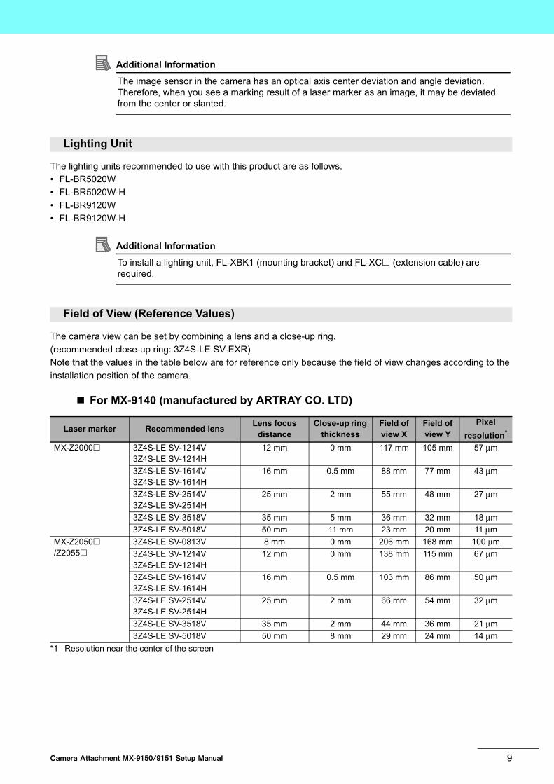
3 Assembly and Installation Method
Follow the steps below to install the camera attachment.
Precautions for Safe Use
• Refer to the diagram below to drill holes for the camera attachment mounting screws, a hole for the laser irradiation port of the marker head, and holes for the camera attachment in the processing table where the marker head and camera attachment are installed. Use materials with sufficient strength such as aluminum (A5052). Use positioning pins only when a repeated installation accuracy is required.
• Secure an outlet for the cable from the camera attachment in the processing table.• Secure a work space for installing the cover or cleaning the cover glass.• Be careful not to damage the workbench or other places with the base positioning pins.
520 10
3
3
25 o
r mor
e25
or m
ore
48
BackFront
Optional Optional
140
110±0.1
178±
0.1
8-M6
160±0.1235±0.1
345±0.1
2-φ4 h7 Press-fit SUS positioning pins

14 Camera Attachment MX-9150/9151 Setup Manual
1 Install the lens and close-up ring onto the camera, then fasten the camera to the camera
mount (sold separately) with screws.
• For MX-915A-AR/915A-FZ* (camera mount: 1)
Mounting screw
• For MX-915A-FQ2* (camera mount: 2)
Mounting screw
* For FZ and FQ2, remove the mount attached to the camera beforehand.
Camera mount model Specification Qty. Torque
MX-915A-AR M2.6 × 5 mm 4 0.36 N·m
MX-915A-FZ M2 × 7 mm 4 0.176 N·m
Specification Qty. Torque
M3 × 12 mm 4 0.63 N·m
Lens
Close-up ring
Camera mount
Lens
Close-up ring
Camera mount
15Camera Attachment MX-9150/9151 Setup Manual
11111111
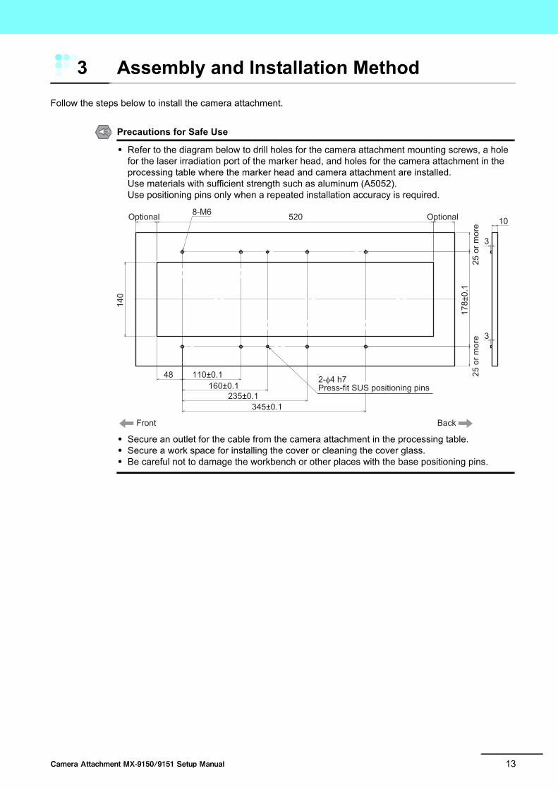
• For MX-915A-S5M2* (camera mount: 2)
Mounting screw
* Remove the mount attached to the camera beforehand.
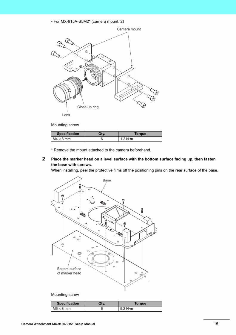
2 Place the marker head on a level surface with the bottom surface facing up, then fasten
the base with screws.
When installing, peel the protective films off the positioning pins on the rear surface of the base.
Mounting screw
Specification Qty. Torque
M4 × 8 mm 6 1.2 N·m
Specification Qty. Torque
M6 × 8 mm 6 5.2 N·m
Lens
Close-up ring
Camera mount
Base
Bottom surface of marker head

16 Camera Attachment MX-9150/9151 Setup Manual
3 Remove the camera cover and rear plate from the base.
4 Temporarily attach the camera mount to the base.
Use the screw holes that do not allow the mirror to touch the lens.
Mounting screw
Precautions for Correct Use
• Do not bump the camera against the mirror when installing the camera mount.• Ensure that you use the attached washers. Failure to do so can cause damage to the
equipment.
Camera mount model Specification Qty.
MX-915A-AR M4 × 6 mm 4
MX-915A-FQ2 M4 × 15 mm 4
MX-915A-FZ M4 × 8 mm 4
MX-915A-S5M2 M4 × 10 mm 4
Camera cover
Rear plate

17Camera Attachment MX-9150/9151 Setup Manual
11111111
5 Fasten the lighting unit to the base with screws, then fasten the lighting cable with cable
ties.
• Positioned for diffuse reflection (install on the side: 2 locations) (recommended)
Fasten the lighting cable at 1 location with a cable tie.
• Positioned for specular reflection (install on the front: 1 location)
Fasten the lighting cable at 2 locations with cable ties.
Cable ties
Lighting units
Lighting cable
Lighting unit
Lighting cable

18 Camera Attachment MX-9150/9151 Setup Manual
6 Place the marker head with the camera attachment installed on the processing table and
fasten with screws.
Screws and washers for mounting the marker head on the processing table are not included.
They must be prepared by the customer.
Use the mounting screws that meet the following conditions:
• Screw diameter: M6 (with washer) 8 locations
• Screw length: 5 to 8 mm should be inserted into the screw holes in the processing table
• Torque: 5.2 N·m
Precautions for Correct Use
• When transporting the marker head, hold the concaved section in front and handle at the back with both hands.
• When placing the marker head on the desk or other surfaces with the camera attachment installed, ensure that the surface is level and there is nothing placed on the surface. The mirror section may be damaged.
Processing table

19Camera Attachment MX-9150/9151 Setup Manual
11111111
7 Have the image displayed on the monitor and adjust the camera position, lens focus, and
iris diaphragm while looking at the image.
8 Fully tighten the screws on the camera mount, then install the camera cover.
Torque for camera mount mounting screws : 1.5 N·m
Camera cover mounting screws
Specification Qty. Torque
M3 × 5 mm 2 0.63 N·m

20 Camera Attachment MX-9150/9151 Setup Manual
9 Pass the lighting cable through, then install the rear plate.
Mounting screw
Specification Qty. Torque
M3 × 5 mm 2 0.63 N·m

21Camera Attachment MX-9150/9151 Setup Manual
11111111
4 Dimensions
138
7
3.5
53
26 198
449345
23511048
3
φ4 depth 5 C0.5+0.10 8-φ6.4
4 depth 5 C0.5+0.10
208
178
178
218
5

22 Camera Attachment MX-9150/9151 Setup Manual
Manual Revision History
The manual revision code is appended at the end of the management number printed at the bottom of the
cover and back cover.
Revision code
Revision date Revision description
A July, 2016 First version
Z378-E1-01Cat. No.
Revision code


OMRON CANADA, INC. • HEAD OFFICEToronto, ON, Canada • 416.286.6465 • 866.986.6766 • www.omron247.com
OMRON ELECTRONICS DE MEXICO • HEAD OFFICEMéxico DF • 52.55.59.01.43.00 • 01-800-226-6766 • [email protected]
OMRON ELECTRONICS DE MEXICO • SALES OFFICEApodaca, N.L. • 52.81.11.56.99.20 • 01-800-226-6766 • [email protected]
OMRON ELETRÔNICA DO BRASIL LTDA • HEAD OFFICESão Paulo, SP, Brasil • 55.11.2101.6300 • www.omron.com.br
OMRON ARGENTINA • SALES OFFICECono Sur • 54.11.4783.5300
OMRON CHILE • SALES OFFICESantiago • 56.9.9917.3920
OTHER OMRON LATIN AMERICA SALES54.11.4783.5300
Authorized Distributor:
Z378-E1-01 07/16 Note: Specifications are subject to change. © 2016 Omron. All Rights Reserved. Printed in U.S.A.
Printed on recycled paper.
OMRON AUTOMATION AMERICAS HEADQUARTERS • Chicago, IL USA • 847.843.7900 • 800.556.6766 • www.omron247.com
OMRON EUROPE B.V. • Wegalaan 67-69, NL-2132 JD, Hoofddorp, The Netherlands. • +31 (0) 23 568 13 00 • www.industrial.omron.eu
Controllers & I/O • Machine Automation Controllers (MAC) • Motion Controllers • Programmable Logic Controllers (PLC) • Temperature Controllers • Remote I/O
Robotics • Industrial Robots • Mobile Robots
Operator Interfaces• Human Machine Interface (HMI)
Motion & Drives• Machine Automation Controllers (MAC) • Motion Controllers • Servo Systems • Frequency Inverters
Vision, Measurement & Identification• Vision Sensors & Systems • Measurement Sensors • Auto Identification Systems
Sensing• Photoelectric Sensors • Fiber-Optic Sensors • Proximity Sensors • Rotary Encoders • Ultrasonic Sensors
Safety • Safety Light Curtains • Safety Laser Scanners • Programmable Safety Systems • Safety Mats and Edges • Safety Door Switches • Emergency Stop Devices • Safety Switches & Operator Controls • Safety Monitoring/Force-guided Relays
Control Components • Power Supplies • Timers • Counters • Programmable Relays • Digital Panel Meters • Monitoring Products
Switches & Relays • Limit Switches • Pushbutton Switches • Electromechanical Relays • Solid State Relays
Software • Programming & Configuration • Runtime