Embed Size (px)
Citation preview

ENGINE MANAGEMENTOPERATING PRINCIPLEA highly advanced engine management system (EMS) has been used to ensure a high power output with cleaner combustion.There are 3 main systems in interaction with the engine management system (EMS):1. Air induction.2. Fuel system.3. Electrical system.NOTE: The cylinders are referenced as 1 front and 2 (rear).
AIR INDUCTIONAir flows through air silencer, air filter, throttle body, intake manifold and then goes into combustion chamber.Throttle BodyThe 46 mm throttle body is mounted on top of intake manifold. Fitted on the throttle body, there is the TPS and idle bypass valve which allows the ECM to control the idle speed while the throttle plate is closed.
TRANSMISSIONGENERAL
For a better understanding, the following illustrations are taken with engine out of vehicle. To perform the following instruction, it is not necessary to remove engine.
This ATV is lubrication free. Never lubricate any components except drive pulley one-way clutch and friction washer.
During assemble / installation, use the torque values and service products as in the exploded views.
Clean threads before applying a threadlocker. Refer to SELF-LOCKING FASTENERS and LOCTITE APPLICATION at the beginning of this manual for complete procedure.
WARNINGS: Torque wrench tightening specifications must strictly be
adhered to. Locking devices (e.g.: locking tabs, elastic stop nuts, self-locking fasteners, cotter pin, etc.) where specified. If the efficiency of a locking device is impaired, it must be renewed.
Never touch CVT while engine is running. Never drive vehicle when CVT cover is removed.

Any drive pulley repairs must be performed by an authorized Can-Am dealer. Subcomponent installation and assembly tolerances require strict adherence to procedures detailed.
The clutch assembly is a precisely balanced unit. Never replace parts with used parts from another clutch assembly.
CAUTION : Never use any type of impact wrench at drive pulley removal
and installation. These pulleys have metric threads. Do not SAE threads puller.
Always tighten puller by hand to ensure that the drive pulley has the same type of threads (metric vs SAE) prior to fully tightening.
PROCEDURESDRIVE BELT
Drive Belt Removal1. Remove:
Distance screws CVT cover Gasket
1 – Distance screw2 – CVT cover 3 – Gasket
NOTE: Remove the center top screw last. This screw allows to support the cover during removal. Open driven pulley with the driven pulley expander.
2. Screw tool in the threaded hole of driven pulley and tighten to open the pulley.
1 – Driven pulley expander2 – Fixed sheave of driven pulley
3. To remove belt, slip the belt over the edge of fixed sheave, as shown.
Drive Belt Inspection1. Inspect belt for cracks, fraying or abnormal wear. Replace if
necessary.2. Check the drive belt width at cord level. Replace if it out of
specification (see table below).
DRIVE BELT WIDTHService limit 30.00 mm
1 – Drive belt2 – Cord in drive belt

Drive Belt InstallationFor installation, reverse the removal procedure. Pay attention to following details.
1 – Arrow printed on belt2 – Drive pulley (front)3 – Driven pulley (rear)4 – Rotation direction
NOTE: The maximum drive belt life span is obtained when the drive belt has the proper rotation direction. Install it so that the arrow printed on belt is pointing towards front of the vehicle, viewed from top.
1. Install the center top screw in first.2. Tighten the distance screw as per following sequence.
DRIVE PULLEY

1 – Belt2 – Drive pulley3 – Driven pulley
Drive Pulley Removal1. Remove belt no. 12. Block the drive pulley. To do this, two procedures can be
followed.
(1) First Possible Procedure:1. Lock crankshaft at TDC position. (Refer to CYLINDER AND
HEAD.)
1 – Crankshaft locking bolt2 – Engine drive shaft (front side)
(2) Second Possible Procedure:1. Block drive pulley with the pulley holding tool.

1 – Pulley holding tool2 – Drive pulley sliding sliding sheave3 – Area to place holding tool hook
2. When the drive pulley is blocked, mark sliding sheave and governor cup to ensure correct reinstallation.
1 – Mark on drive pulley sliding sheave2 – Mark on governor cup
3. Unscrew the drive pulley screw (right hand thread), then remove it as well as the conical spring washer and thrust washer.

1 – Drive pulley screw2 – Conical spring washer3 – Thrust washerWARNING: Sliding sheave of drive pulley is spring loaded.
4. Push with your hand the sliding sheave no.2 of the drive pulley then remove the screw completely.
5. Slowly release sliding sheave.6. Screw drive pulley puller in fixed sheave and remove fie
pulley.
1 – Drive pulley puller2 – Fixed sheave
Governor Cup Disassembly1. Carefully lift governor cup no.3 until slider shoes no.4 come at
their highest position into guides.NOTE: The following procedure is not necessary except if roller must be removed. Refer to INSPECTION before proceeding.
2. Remove slider shoes out of each bearing sleeve. Use a flat screwdriver if necessary.

1 – Slider shoe
3. Put governor cup on a vice to push out bearing sleeve of roller in the foreseen direction (against arrow). Use an appropriate punch (diameter of punch must be smaller than the bearing sleeve diameter).CAUTION: Do not clamp the governor cup in the vice to push out bearing sleeve. Governor cup will be damaged.
1 – Punch 2 – Vice
1 – Removal direction

2 – Assembly direction
NOTE: Use protection plates to avoid marks and/ or damages to the governor cup.
CAUTION: Always replace all rollers at the same time. Partly worn rollers may cause damage to the CVT system.NOTE: Whenever removing a governor cup with already two marked boxes replace it by a new one.
Sliding Sheave Disassembly1. Unscrew lock nut and remove centrifugal level pivot bolt. This
drive pulley is equipped with 6 levers. 2. Remove centrifugal lever no.7 and both thrust washers no. 8.
1 – Lock nut2 – Centrifugal lever pivot bolt3 – Centrifugal lever4 – Thrust washers
Fixed Sheave Disassembly1. Remove friction washer no. 12.2. Pull and rotate one-way clutch slowly until the sheave of
spring sleeves are visible.

WARNING: Always wear safety glasses to remove spring sleeves.
1 – One-way clutch2 – Fixed sheave3 – Spring sleeve area
3. Hold both spring sleeves with fingers and release when one-way clutch is disengaged.
1 – Springs2 – Spring sleeves
Drive Pulley Cleaning1. Clean pulley faces and shaft with fine steel wool and dry cloth.2. Use a paper towel with pulley flange cleaner cleaning solvent,
clean crankshaft tapered end and the taper inside the fixed sheave of the drive pulley, crankshaft threads and threads of drive pulley screw no. 15.CAUTION : Avoid contact between cleaner and crankshaft seal

because damage any occur.3. Remove all hardened oil deposits that have baked on
crankshaft and pulley tapered surfaces with coarse or medium steel wool and/or sand paper no. 600.CAUTION : Do not use any other type of abrasive.
4. Reclean mounting surfaces with paper towel and pulley flange cleaner.
5. Wipe off the mounting surfaces with a clean, dry paper towel.CAUTION : Mounting surfaces must be free of any oil, cleaner or towel residue.
1 – Taper of fixed sheave
NOTE: Only use petrol base cleaner when cleaning bushings no.10 and no.11.CAUTION : Do not use acetone to clean bushing.
Drive Pulley InspectionDrive pulley should be inspected annually.
Governor Cup InspecctionCheck governor cup for cracks or other visible damages. Replace if necessary.
Roller and Slider Shoe Inspection1. Check each roller for roundness of external.2. Check if rollers move freely.
CAUTION: When replacing rollers and slider shoes, always replace all rollers and slider shoes at the same time.
3. Check slider shoes for visible wear and replace if damaged.NOTE : If necessary, use a screwdriver to remove slider shoes.

1 – Roller2 – Slider shoe3 – Roller outer diameter
ROLLER OUTER DIAMETERNEW 13.70—13.80 mmSERVICE LIMIT 13.20 mm
ROLLER INNER DIAMETERNEW 8.05—8.15 mmSERVICE LIMIT 9.00 mm
Centrifugal Lever Pivot Bolt Inspection1. Measure diameter of centrifugal lever pivot bolt no. 9, replace
if it is out of specification.
1 – Centrifugal lever pivot bolt2 – Measure diameter here
Centrifugal Lever Pivot Bolt Diameter
Nominal 6.078—6.100 mmService Limit 6.00 mm
Centrifugal Lever Inspection1. Check bushing diameter in the centrifugal lever no. 7 for wear.
Replace centrifugal lever if necessary.
Centrifugal Lever Bore Diameter

Nominal 6.035—6.078 mmService Limit 6.200mm
2. Replace centrifugal lever, thrust washers, centrifugal lever pivot bolts and lock nuts if the contact surfaces show heavy visible wear.
1 – Lock nut2 – Centrifugal lever pivot bolt3 – Centrifugal lever4 – Thrust washers5 – Contact surface to the roller
WARNING: When replacing centrifugal levers, always replace all levers at the same time. Otherwise, drive pulley misbalancing will occur because of levers difference.
Sliding Sheave Inspection1. Check sliding sheave for cracks and sliding contact surface for
excessive wear. Replace sliding sheave if necessary.2. Measure centrifugal lever pivot bolt bores. Replace sliding
sheave if bores are out of specification or otherwise damaged.

A – Centrifugal lever pivot bolt bore diameter
3. Measure bushing diameters of sliding sheave.4. Use a dial bore gauge to measure bushing diameter.
Measuring point must be at least 5 mm from bushing edge.
1 – Bushing on fixed sheave side2 – Bore diameter of bushing
Sliding Sheave Large Bushing
Nominal 55.00—55.04 mm
Service Limit 55.20 mm
Centrifugal Lever Pivot BoltBore Diameter
Nominal 6.113—6.171 mm
Service Limit 6.300 mm

1 – Bushing on governor cup side2 – Bore diameter of bushing
5. Replace sliding sheave if bushings no. 10 and/ or no. 11 is (are) out of specification. Visually inspect coatings.
Fixed Sheave Inspection1. Check fixed sheave contact surface to the governor cup for
scorings and other damages. If so, replace fixed sheave.
1 – Visually check here
2. Check for any marks on fixed sheave plate. Replace if necessary.
Spring Inspection1. Measure spring free length and squareness. If the spring is out
of specification, replace by a new one.Spring Free Length
Service Limit 85 mmClutch Spring Squareness
Service Limit 4 mm
One-Way Clutch Inspection1. Check bearings for excessive play and smooth operation.
Replace one-way clutch if necessary.CAUTION: Be careful not to damage the inside of one-way clutch during bearing removal.
Sliding Sheave Small BushingNominal 30.00—30.04
mmService Limit 30.200 mm

1 – One-way clutch2 – Bearings
2. Measure length of spring sleeve no. 14 and check if edges on top of the spring sleeve are excessively worn. If they out of specifications, Replace both spring sleeve at the same time.
Spring Sleeve LengthNominal 9.2—9.4 mmService Limit 9 mm
One-Way Clutch AssemblyThe assembly is the reverse of the disassembly procedure. Pay attention to following:
Using isoflex grease Topas NB 52, lubricate spring and spring sleeve no.14 and between on-way clutch bearings no.13.
Friction Washer AssemblyThe assembly is the reverse of the disassembly procedure. Pay attention to following details.
Apply isofex grease Topas NB 52 on both sides of friction washer no.12.
Friction washer has to be assembled with collar towards to the one-way clutch.

1 – Friction washer2 – Collar3 – One-way clutch
Sliding Sheave AssemblyThe assembly is the reverse of the disassembly procedure. Pay attention to following details.
Install centrifugal levers no.7 with their thrust washers no.8. CAUTION: Centrifugal levers must move easily after
installation.
Governor Cup AssemblyThe assembly is the reverse of the disassembly procedure. Pay attention to following details.
Rebuild governor cup with new bearing sleeves, thrust washers no. 6, rollers, and slider shoes (no protrusion).
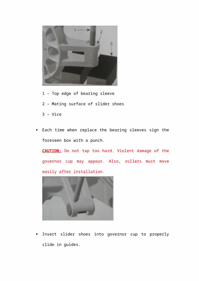
1 – Top edge of bearing sleeve2 – Mating surface of slider shoes3 – Vice
Each time when replace the bearing sleeves sign the foreseen box with a punch.

CAUTION: Do not tap too hard. Violent damage of the governor cup may appear. Also, rollers must move easily after installation.
Insert slider shoes into governor cup to properly slide in guides.
InstallationFor installation, reverse the removal procedure. Pay attention to the following details.WARNING: Do not apply antiseize or any lubricant on crankshaft and drive pulley tapers.CAUTION: Never use any type of impact wrench at drive pulley removal and installation.
1. Clean mounting surface as described in CLEANING.2. Install drive pulley on crankshaft extension.
CAUTION: Do not forget to place thrust washer prior to install conical spring washer.
3. Install conical spring washer with its concave side towards drive pulley then install drive pulley screw.
1 – Drive pulley screw2 – Conical spring washer

3 – Thrust washer
WARNING: Never substitute conical spring washer and/ or screw with jobber ones. Always use BRP genuine parts for this particular case.
4. To torque the drive pulley screw, block the drive pulley. Refer to the beginning of this section for the two possible procedures.
5. When the drive pulley is blocked, torque screw to 100 N/m.
1 – Pulley holding tool2 – Drive pulley removal / installation area
DRIVEN PULLEY
Driven Pulley Removal 1. Remove drive belt. (Refer to DRIVE BELT.)2. Using the pulley holding tool, hold the driven pulley during the
removal of the driven pulley screw. Do not remove screw completely.

3. Push the driven pulley and maintain it in this position during the removal of screw. Remove driven pulley screw and washer.
1 – Driven pulley screw2 – Thrust washer3 – Driven pulley fixed sheave
WARNING: Driven pulley is spring loaded. Hold driven clutch pulley tight and slowly remove the driven pulley screw to release spring tension.
4. Remove the driven pulley with the spring, cam and the plate.

1 – Fixed sheave of driven pulley2 – Sliding sheave of driven pulley3 – Spring 4 – Cam5 – Plate
Fixed Sheave Disassembly1. Remove retaining ring and lift torque gear.
1 – Retaining ring2 – Torque gear3 – Fixed sheave of driven pulley
NOTE: The following procedure is not necessary except if ball bearing or shaft must be removed. Refer to INSPECTION before proceeding.
2. Heat ball bearing area up to 100℃ before removing the ball bearing.
3. Use a soft hammer to push shaft with bearing no. 17 out of fixed sheave.

1 – Soft hammer2 – Shaft
4. Remove shaft from ball bearing.5. Remove distance sleeve and O-ring no. 26 from countershaft.6. Replace O-ring if brittle, hard or damaged.
1 – O-ring2 – Distance sleeve
Cleaning the TransmissionNote: When a dust deposit has to be removed from the cam or the shaft, use dry cloth.
1. Clean pulley faces and shaft with fine steel wool and dry cloth.2. Use pulley flange cleaner to clean driven pulley.3. Clean the CVT air guide area from contamination.4. Using a paper towel with pulley flange cleaner, to clean
countershaft end and the inside of the shaft no. 23.CAUTION : To avoid damage, make sure cleaner does not contact the countershaft oil seal.

1 – Countershaft support2 – Countershaft oil seal
Sliding Sheave Inspection1. Check sliding sheave for cracks and sliding contact surface for
excessive wear. Replace sliding sheave if necessary.2. Check bushings no. 22 for cracks, scratch and for free
movement when assembled to sliding sheave.3. Using a dial bore gauge measure bushing diameter. Measuring
point must be at least 5 mm from bushing edge.4. This bushing cannot be replaced. Replace sliding sheave if
bushings no. 22 are out of specification. Visually inspect coatings.
1 – Bushings2 – Backside of sliding sheave of driven pulley
Bushing Bore Diameter
Nominal 30.06 – 30.10 mm
Service Limit 30.20 mm
Fixed Sheave Inspection

1. Check fixed sheave for cracks and excessive wear. Replace fixed sheave if necessary.
2. Check ball bearing for free play and smooth operation. Replace if necessary.
3. Check shaft for heavy wear or visible damage. Replace if necessary.
4. If the shaft is removed, using a dial bore gauge, measure bushing diameter. Measuring point must be at least 5mm from bushing edge. This bushing can not be replaced. Replace fixed sheave if bushing no. 18 is out of specification. Visually inspect coatings.
Bushing Bore Diameter
Nominal 30.06 – 30.10 mm
Service Limit 30.20 mm
5. Check torque gear for visible damage and cracks. Measure wear limit with a caliper.
1 – Measurement inside2 – Measurement outside
Wear on Teeth (Both Sides)Service Limit 7.50 mm

Cam Inspection1. Check cam for visible damage and wear limit with a caliper.
1 – Contact surface2 – CaliperA – Width to be measured due to wear on contact surface
Width on Top SurfaceService Limit 9.00 mm
1 – Caliper2 – Sliding sheave3 – Contact surfaceA – Wear on contact surface to measure

Wear on Contact SurfaceService Limit 1.00 mm
Spring Inspection
1. Measure spring free length and squareness. Replace the spring if it is out of specification.
Spring Free LengthService Limit 125 mm
Clutch Spring SquarenessService Limit 3.80 mm
Driven Pulley Assembly For installation, reverse the removal procedure. Pay attention to following details.
1. Heat ball bearing area up to 100℃ before ball bearing installation.NOTE : Place new ball bearing in a freezer for 10 minutes before installation.
2. Install ball bearing with the writing on top and push only on the outer ring.
1 – Ball bearing2 – Fixed sheave of driven pulley
CAUTION : Do not use hammer, use press machine only.

1 – Shaft2 – Fixed sheave3 – Press machine
3. Install torque gear then secure it with retaining ring.
1 – Retaining ring2 – Torque gear3 – fixed sheave of driven pulley
InstallationFor installation, reverse the removal procedure. Pay attention to the following details.
1. Place O-ring no. 26 on countershaft splines and move it with distance sleeve no. 25 in end position.CAUTION: Chamfer on inside diameter of the distance sleeve must face gearbox side.
1 – O-ring2 – Distance sleeve3 – Chamfered of distance sleeve
2. Install cam retainer on countershaft end the right way.
1 – Sharp edge of cam retainer to engine side2 – Countershaft spline3 – Inscription
3. Install cam no. 24.4. Install sliding sheave no. 21 into fixed sheave no.16.5. Place spring behind sliding sheave then align driven pulley
with cam.

1 – Cam 2 – Spring3 – Driven pulley
6. With your hand, push the driven pulley on the shaft to compress the spring. Install the driven pulley screw and thrust washer.WARNING: Driven pulley is a spring loaded system.
1 – Driven pulley screw2 – Thrust washer3 – Driven pulley fixed sheaveNOTE: Driven pulley end-play is 0.
7. Torque driven pulley screw.

CVT AIR GUIDE
CVT Air Guide Removal1. Remove:
CVT cover Drive belt Drive pulley Driven pulley
2. Unscrew the clamps retaining the CVT air hoses3. Remove CVT air guide.
CVT Air Guide Inspection1. Clean CVT air guide from contamination.2. Check O-rings if brittle, hard or damaged. Replace if
necessary.
1 – CVT air guide2 – O-rings
CVT Air Guide InstallationFor installation, reverse the removal procedure.