Embed Size (px)
Citation preview
Can flat-ramp-flat fault geometry be inferred from fold shape?:A comparison of kinematic and mechanical folds
Heather M. Savage*, Michele L. Cooke
Morrill Science Center, University of Massachusetts Amherst, 611 North Pleasant St., Amherst, MA 01003, USA
Received 15 July 2002; received in revised form 7 November 2002; accepted 10 April 2003
Abstract
The inference of fault geometry from suprajacent fold shape relies on consistent and verified forward models of fault-cored folds, e.g.suites of models with differing fault boundary conditions demonstrate the range of possible folding. Results of kinematic (fault-parallel flow)and mechanical (boundary element method) models are compared to ascertain differences in the way the two methods simulate flexureassociated with slip along flat-ramp-flat geometry. These differences are assessed by systematically altering fault parameters in each modeland observing subsequent changes in the suprajacent fold shapes. Differences between the kinematic and mechanical fault-fold relationshipshighlight the differences between the methods. Additionally, a laboratory fold is simulated to determine which method might best predictfault parameters from fold shape. Although kinematic folds do not fully capture the three-dimensional nature of geologic folds, mechanicalmodels have non-unique fold-fault relationships. Predicting fault geometry from fold shape is best accomplished by a combination of the twomethods.q 2003 Elsevier Ltd. All rights reserved.
Keywords: Fault-bend folding; Mechanical models; Kinematic models; Fault geometry prediction
1. Introduction
Constraining unexposed or poorly resolved subsurfacefault geometry from observed fold shape has far-reachingimportance, from assessment of seismic hazard to evalu-ation of hydrocarbon potential. Fault-bend folds have longbeen recognized as forming due to slip along subjacentfaults with flat-ramp-flat geometry in areas of thin-skinneddeformation (e.g. Rich, 1934; Mitra and Sussman, 1997)and past studies have shown that fault geometry has asystematic influence on aspects of fold shape such as axialtrace orientation (Rowan and Linares, 2000), fold tightness(Allmendinger and Shaw, 2000) and fold terminations(Wilkerson et al., 2002). Within extensional environmentsfault depth and dip may be determined from the associatedroll-over anticline, as long as the hanging wall stratigraphyis accurately determined (Williams and Vann, 1987; Kerrand White, 1992, 1994).
Both kinematic and mechanical models have been usedto analyze fault-cored folds. Kinematic models, whichbalance the geometry of the deforming system withoutincorporating force or rheology, have been used extensivelyto study fault-bend folding (e.g. Suppe, 1983; Wilkersonet al., 1991; Salvini and Storti, 2001). Mechanical modelsutilize continuum mechanics to simulate deformation andhave been used in the past to examine folding associatedwith fault ramp tips (e.g. Cooke and Pollard, 1997; Johnsonand Johnson, 2001) and flat-ramp-flat geometry (e.g. Bergerand Johnson, 1980; Kilsdonk and Fletcher, 1989; Strayer andHudleston, 1997). A recent comparison of mechanical andkinematic trishear models of fault-tip folds (Johnsonand Johnson, 2001) demonstrates the insights gained fromcomparative studies and exposes the dearth of such studiesfor fault-bend-folding. Within this study, two numericalmodels, one kinematic (fault parallel flow) and onemechanical (boundary element method), show how foldsrespond to changes in flat-ramp-flat fault geometry usingthese different methods. We perform a sensitivity analysis toascertain which fault parameters are most influential overfold shape in each method. When kinematic and mechanicalmodels with identical fault configurations produce similar
0191-8141/03/$ - see front matter q 2003 Elsevier Ltd. All rights reserved.
doi:10.1016/S0191-8141(03)00080-4
Journal of Structural Geology 25 (2003) 2023–2034
www.elsevier.com/locate/jsg
* Corresponding author. Present address, Department of Geosciences,
The Pennsylvania State University, University Park, PA 16802, USA. Tel.:!1-413-545-2286; fax: !1-413-545-1200.
E-mail address: [email protected] (H.M. Savage).
changes to a feature of the fold shape, the usefulness of thatfold feature for inferring fault geometry is suggested. Whenthe methods disagree, an attempt is made to determine if oneset of generated fold shapes is more reasonable throughcomparison with field or laboratory models. Similarsensitivity analyses have focused on the effects of faultgeometry (dip, ramp height, flat length, displacement) onfold shape in kinematic models (Rowan and Linares, 2000)and in mechanical models, along with the role of anisotropy,for fault propagation folds (Johnson and Johnson, 2001).
Finally, we perform kinematic and mechanical simu-lations of a laboratory fold with well-constrained faultgeometry (Chester et al., 1991) in order to assess howaccurately the models can predict a known fault geometryby matching the fold shape. The laboratory fold is simulatedby iteratively altering fault geometry. The kinematic andmechanical best-fitting fault geometries are compared withthe laboratory fault. Positive correlation of both fold andfault shapes supports use of the method for predictingsubsurface fault geometry.
2. Modeling methods
2.1. Mechanical modeling
Mechanical modeling is based upon the three principlesof continuum mechanics (e.g. Fung, 1969; Means, 1976;Timoshenko and Goodier, 1934). The first involvesconstitutive relationships, which relate the applied stressto the resulting strain in the rock (e.g. Means, 1976). Thesecond principle of continuum mechanics states that therock body must be in equilibrium; the body deforms butcannot translate or rotate (e.g. Means, 1976). The thirdprinciple, compatibility, requires that the displacement ineach direction be continuous and single-valued to preventgaps and overlaps from occurring (e.g. Means, 1976).
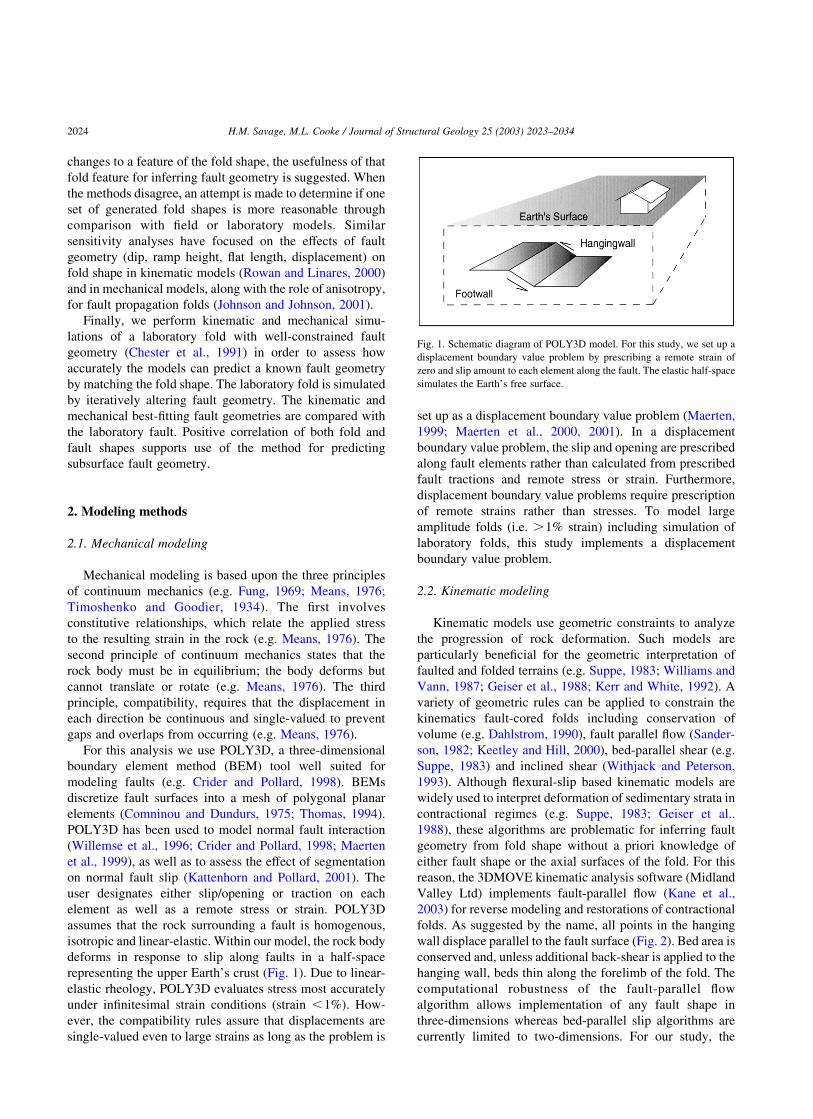
For this analysis we use POLY3D, a three-dimensionalboundary element method (BEM) tool well suited formodeling faults (e.g. Crider and Pollard, 1998). BEMsdiscretize fault surfaces into a mesh of polygonal planarelements (Comninou and Dundurs, 1975; Thomas, 1994).POLY3D has been used to model normal fault interaction(Willemse et al., 1996; Crider and Pollard, 1998; Maertenet al., 1999), as well as to assess the effect of segmentationon normal fault slip (Kattenhorn and Pollard, 2001). Theuser designates either slip/opening or traction on eachelement as well as a remote stress or strain. POLY3Dassumes that the rock surrounding a fault is homogenous,isotropic and linear-elastic. Within our model, the rock bodydeforms in response to slip along faults in a half-spacerepresenting the upper Earth’s crust (Fig. 1). Due to linear-elastic rheology, POLY3D evaluates stress most accuratelyunder infinitesimal strain conditions (strain ,1%). How-ever, the compatibility rules assure that displacements aresingle-valued even to large strains as long as the problem is
set up as a displacement boundary value problem (Maerten,1999; Maerten et al., 2000, 2001). In a displacementboundary value problem, the slip and opening are prescribedalong fault elements rather than calculated from prescribedfault tractions and remote stress or strain. Furthermore,displacement boundary value problems require prescriptionof remote strains rather than stresses. To model largeamplitude folds (i.e. .1% strain) including simulation oflaboratory folds, this study implements a displacementboundary value problem.
2.2. Kinematic modeling
Kinematic models use geometric constraints to analyzethe progression of rock deformation. Such models areparticularly beneficial for the geometric interpretation offaulted and folded terrains (e.g. Suppe, 1983; Williams andVann, 1987; Geiser et al., 1988; Kerr and White, 1992). Avariety of geometric rules can be applied to constrain thekinematics fault-cored folds including conservation ofvolume (e.g. Dahlstrom, 1990), fault parallel flow (Sander-son, 1982; Keetley and Hill, 2000), bed-parallel shear (e.g.Suppe, 1983) and inclined shear (Withjack and Peterson,1993). Although flexural-slip based kinematic models arewidely used to interpret deformation of sedimentary strata incontractional regimes (e.g. Suppe, 1983; Geiser et al..1988), these algorithms are problematic for inferring faultgeometry from fold shape without a priori knowledge ofeither fault shape or the axial surfaces of the fold. For thisreason, the 3DMOVE kinematic analysis software (MidlandValley Ltd) implements fault-parallel flow (Kane et al.,2003) for reverse modeling and restorations of contractionalfolds. As suggested by the name, all points in the hangingwall displace parallel to the fault surface (Fig. 2). Bed area isconserved and, unless additional back-shear is applied to thehanging wall, beds thin along the forelimb of the fold. Thecomputational robustness of the fault-parallel flowalgorithm allows implementation of any fault shape inthree-dimensions whereas bed-parallel slip algorithms arecurrently limited to two-dimensions. For our study, the
Fig. 1. Schematic diagram of POLY3D model. For this study, we set up adisplacement boundary value problem by prescribing a remote strain of
zero and slip amount to each element along the fault. The elastic half-space
simulates the Earth’s free surface.
H.M. Savage, M.L. Cooke / Journal of Structural Geology 25 (2003) 2023–20342024
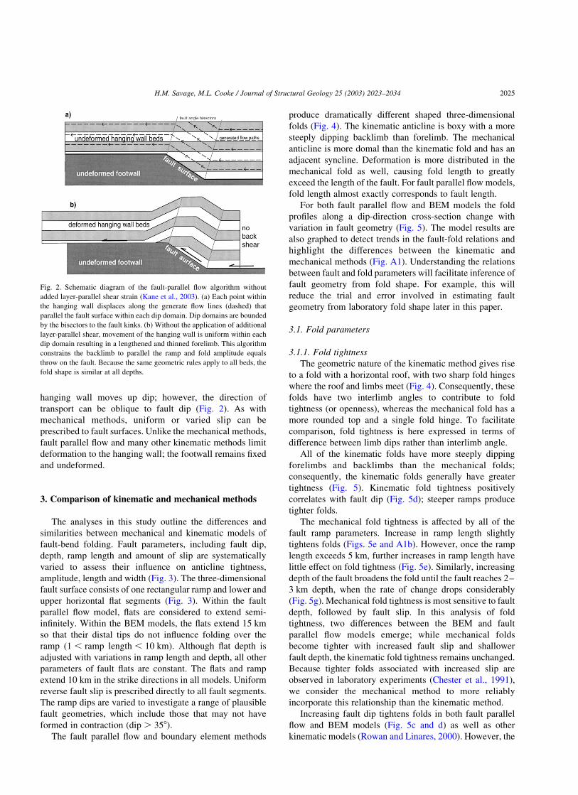
hanging wall moves up dip; however, the direction oftransport can be oblique to fault dip (Fig. 2). As withmechanical methods, uniform or varied slip can beprescribed to fault surfaces. Unlike the mechanical methods,fault parallel flow and many other kinematic methods limitdeformation to the hanging wall; the footwall remains fixedand undeformed.
3. Comparison of kinematic and mechanical methods
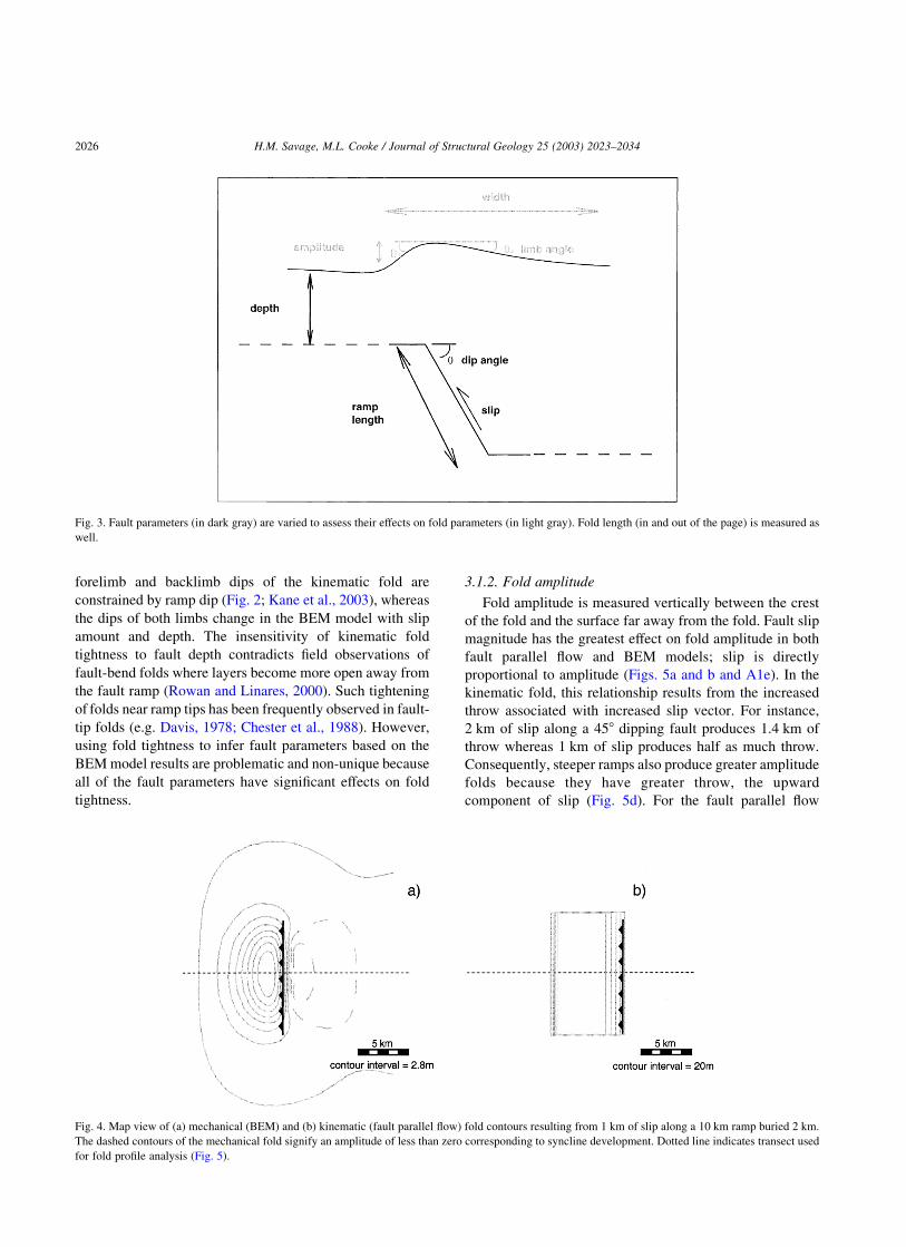
The analyses in this study outline the differences andsimilarities between mechanical and kinematic models offault-bend folding. Fault parameters, including fault dip,depth, ramp length and amount of slip are systematicallyvaried to assess their influence on anticline tightness,amplitude, length and width (Fig. 3). The three-dimensionalfault surface consists of one rectangular ramp and lower andupper horizontal flat segments (Fig. 3). Within the faultparallel flow model, flats are considered to extend semi-infinitely. Within the BEM models, the flats extend 15 kmso that their distal tips do not influence folding over theramp (1 , ramp length , 10 km). Although flat depth isadjusted with variations in ramp length and depth, all otherparameters of fault flats are constant. The flats and rampextend 10 km in the strike directions in all models. Uniformreverse fault slip is prescribed directly to all fault segments.The ramp dips are varied to investigate a range of plausiblefault geometries, which include those that may not haveformed in contraction (dip . 358).
The fault parallel flow and boundary element methods
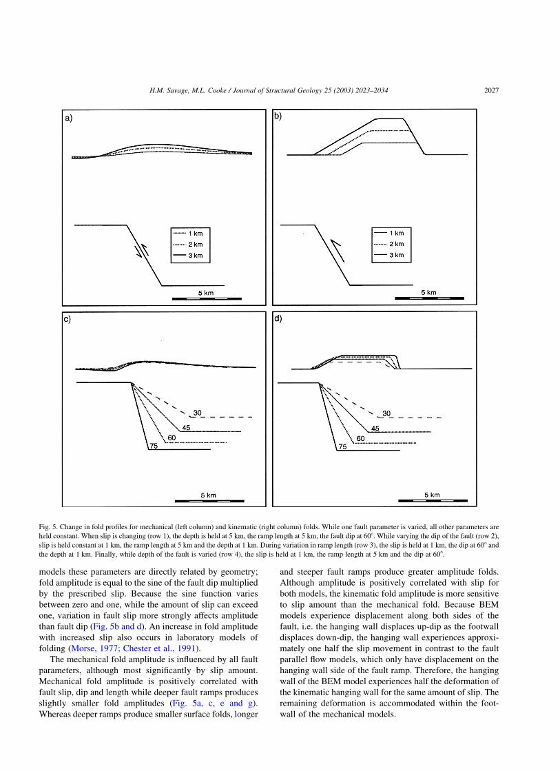
produce dramatically different shaped three-dimensionalfolds (Fig. 4). The kinematic anticline is boxy with a moresteeply dipping backlimb than forelimb. The mechanicalanticline is more domal than the kinematic fold and has anadjacent syncline. Deformation is more distributed in themechanical fold as well, causing fold length to greatlyexceed the length of the fault. For fault parallel flow models,fold length almost exactly corresponds to fault length.
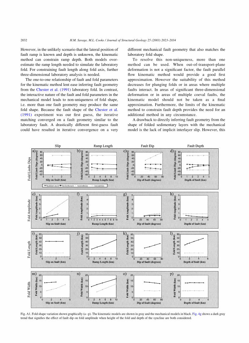
For both fault parallel flow and BEM models the foldprofiles along a dip-direction cross-section change withvariation in fault geometry (Fig. 5). The model results arealso graphed to detect trends in the fault-fold relations andhighlight the differences between the kinematic andmechanical methods (Fig. A1). Understanding the relationsbetween fault and fold parameters will facilitate inference offault geometry from fold shape. For example, this willreduce the trial and error involved in estimating faultgeometry from laboratory fold shape later in this paper.
3.1. Fold parameters
3.1.1. Fold tightnessThe geometric nature of the kinematic method gives rise
to a fold with a horizontal roof, with two sharp fold hingeswhere the roof and limbs meet (Fig. 4). Consequently, thesefolds have two interlimb angles to contribute to foldtightness (or openness), whereas the mechanical fold has amore rounded top and a single fold hinge. To facilitatecomparison, fold tightness is here expressed in terms ofdifference between limb dips rather than interlimb angle.
All of the kinematic folds have more steeply dippingforelimbs and backlimbs than the mechanical folds;consequently, the kinematic folds generally have greatertightness (Fig. 5). Kinematic fold tightness positivelycorrelates with fault dip (Fig. 5d); steeper ramps producetighter folds.
The mechanical fold tightness is affected by all of thefault ramp parameters. Increase in ramp length slightlytightens folds (Figs. 5e and A1b). However, once the ramplength exceeds 5 km, further increases in ramp length havelittle effect on fold tightness (Fig. 5e). Similarly, increasingdepth of the fault broadens the fold until the fault reaches 2–3 km depth, when the rate of change drops considerably(Fig. 5g). Mechanical fold tightness is most sensitive to faultdepth, followed by fault slip. In this analysis of foldtightness, two differences between the BEM and faultparallel flow models emerge; while mechanical foldsbecome tighter with increased fault slip and shallowerfault depth, the kinematic fold tightness remains unchanged.Because tighter folds associated with increased slip areobserved in laboratory experiments (Chester et al., 1991),we consider the mechanical method to more reliablyincorporate this relationship than the kinematic method.
Increasing fault dip tightens folds in both fault parallelflow and BEM models (Fig. 5c and d) as well as otherkinematic models (Rowan and Linares, 2000). However, the
Fig. 2. Schematic diagram of the fault-parallel flow algorithm without
added layer-parallel shear strain (Kane et al., 2003). (a) Each point withinthe hanging wall displaces along the generate flow lines (dashed) that
parallel the fault surface within each dip domain. Dip domains are bounded
by the bisectors to the fault kinks. (b) Without the application of additional
layer-parallel shear, movement of the hanging wall is uniform within eachdip domain resulting in a lengthened and thinned forelimb. This algorithm
constrains the backlimb to parallel the ramp and fold amplitude equals
throw on the fault. Because the same geometric rules apply to all beds, thefold shape is similar at all depths.
H.M. Savage, M.L. Cooke / Journal of Structural Geology 25 (2003) 2023–2034 2025
forelimb and backlimb dips of the kinematic fold areconstrained by ramp dip (Fig. 2; Kane et al., 2003), whereasthe dips of both limbs change in the BEM model with slipamount and depth. The insensitivity of kinematic foldtightness to fault depth contradicts field observations offault-bend folds where layers become more open away fromthe fault ramp (Rowan and Linares, 2000). Such tighteningof folds near ramp tips has been frequently observed in fault-tip folds (e.g. Davis, 1978; Chester et al., 1988). However,using fold tightness to infer fault parameters based on theBEMmodel results are problematic and non-unique becauseall of the fault parameters have significant effects on foldtightness.
3.1.2. Fold amplitude
Fold amplitude is measured vertically between the crestof the fold and the surface far away from the fold. Fault slipmagnitude has the greatest effect on fold amplitude in bothfault parallel flow and BEM models; slip is directlyproportional to amplitude (Figs. 5a and b and A1e). In thekinematic fold, this relationship results from the increasedthrow associated with increased slip vector. For instance,2 km of slip along a 458 dipping fault produces 1.4 km ofthrow whereas 1 km of slip produces half as much throw.Consequently, steeper ramps also produce greater amplitudefolds because they have greater throw, the upwardcomponent of slip (Fig. 5d). For the fault parallel flow
Fig. 3. Fault parameters (in dark gray) are varied to assess their effects on fold parameters (in light gray). Fold length (in and out of the page) is measured as
well.
Fig. 4. Map view of (a) mechanical (BEM) and (b) kinematic (fault parallel flow) fold contours resulting from 1 km of slip along a 10 km ramp buried 2 km.The dashed contours of the mechanical fold signify an amplitude of less than zero corresponding to syncline development. Dotted line indicates transect used
for fold profile analysis (Fig. 5).
H.M. Savage, M.L. Cooke / Journal of Structural Geology 25 (2003) 2023–20342026
models these parameters are directly related by geometry;fold amplitude is equal to the sine of the fault dip multipliedby the prescribed slip. Because the sine function variesbetween zero and one, while the amount of slip can exceedone, variation in fault slip more strongly affects amplitudethan fault dip (Fig. 5b and d). An increase in fold amplitudewith increased slip also occurs in laboratory models offolding (Morse, 1977; Chester et al., 1991).
The mechanical fold amplitude is influenced by all faultparameters, although most significantly by slip amount.Mechanical fold amplitude is positively correlated withfault slip, dip and length while deeper fault ramps producesslightly smaller fold amplitudes (Fig. 5a, c, e and g).Whereas deeper ramps produce smaller surface folds, longer
and steeper fault ramps produce greater amplitude folds.Although amplitude is positively correlated with slip forboth models, the kinematic fold amplitude is more sensitiveto slip amount than the mechanical fold. Because BEMmodels experience displacement along both sides of thefault, i.e. the hanging wall displaces up-dip as the footwalldisplaces down-dip, the hanging wall experiences approxi-mately one half the slip movement in contrast to the faultparallel flow models, which only have displacement on thehanging wall side of the fault ramp. Therefore, the hangingwall of the BEM model experiences half the deformation ofthe kinematic hanging wall for the same amount of slip. Theremaining deformation is accommodated within the foot-wall of the mechanical models.
Fig. 5. Change in fold profiles for mechanical (left column) and kinematic (right column) folds. While one fault parameter is varied, all other parameters areheld constant. When slip is changing (row 1), the depth is held at 5 km, the ramp length at 5 km, the fault dip at 608. While varying the dip of the fault (row 2),
slip is held constant at 1 km, the ramp length at 5 km and the depth at 1 km. During variation in ramp length (row 3), the slip is held at 1 km, the dip at 608 andthe depth at 1 km. Finally, while depth of the fault is varied (row 4), the slip is held at 1 km, the ramp length at 5 km and the dip at 608.
H.M. Savage, M.L. Cooke / Journal of Structural Geology 25 (2003) 2023–2034 2027
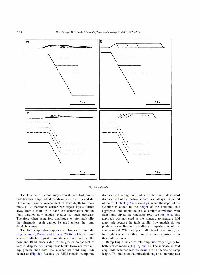
The kinematic method may overestimate fold ampli-tude because amplitude depends only on the slip and dipof the fault and is independent of fault depth for thesemodels. As mentioned earlier, we expect layers furtheraway from a fault tip to have less deformation but thefault parallel flow models predict no such decrease.Therefore when using fold amplitude to infer fault slip,the kinematic result cannot be used unless the rampdepth is known.
The fold shape also responds to changes in fault dip(Fig. 5c and d; Rowan and Linares, 2000). Folds overlyingsteeper faults have greater amplitude in both fault parallelflow and BEM models due to the greater component ofvertical displacement along these faults. However, for faultdip greater than 608, the mechanical fold amplitudedecreases (Fig. 5c). Because the BEM models incorporate
displacement along both sides of the fault, downwarddisplacement of the footwall creates a small syncline aheadof the forelimb (Fig. 5a, c, e and g). When the depth of thesyncline is added to the height of the anticline, thisaggregate fold amplitude has a similar correlation withfault ramp dip as the kinematic fold (see Fig. A1). Thisapproach was not used as the standard to measure foldamplitude because the fault parallel flow models do notproduce a syncline and the direct comparison would becompromised. While ramp dip affects fold amplitude, thefold tightness and width are more accurate constraints onthis fault parameter.
Ramp length increases fold amplitude very slightly forboth sets of models (Fig. 5g and h). The increase in foldamplitude becomes less discernible with increasing ramplength. This indicates that miscalculating an 8-km ramp as a
Fig. 5 (continued )
H.M. Savage, M.L. Cooke / Journal of Structural Geology 25 (2003) 2023–20342028
10-km ramp will not affect the results as much asmiscalculating a 1-km ramp as a 3-km ramp.
3.1.3. Fold length
Slightly different methods of fold length measurementare used for fault parallel flow and BEM models because ofthe difference in fold termination style. Mechanical folds donot terminate as abruptly as kinematic folds (Fig. 4). For thefault parallel flow models, the fold length extends to thelocations where fold amplitude along the fold heightabruptly drops to zero. The mechanical fold terminationsare estimated where the amplitude along the fold axis dropsto 1% of the maximum amplitude, because the surface is notexactly zero after folding. One of the most significantdistinctions between the models is the influence of faultlength on suprajacent folding. The kinematic fold lengthdepends solely on the length of the fault at a nearly one-to-one ratio; no other fault parameter affects fold length.Because the fault parallel flow method is created by linkingtwo-dimensional cross-sections, material only moves withinthe user-prescribed transport plane. Consequently, the foldtakes on a boxy shape, with the nose of the fold falling offabruptly above the lateral end of the fault (Fig. 4b). Incontrast, the mechanical fold length ranges from two to fivetimes the length of the fault. The mechanical fold lengthscorrelate positively with fault dip, depth and slightly withramp length because in continuum mechanics, deformationat one point influences the surrounding material. Todistinguish between the kinematic and mechanical predic-tions for fault length, high quality three-dimensional seismicor laboratory data would be needed to ascertain how farnatural folds extend beyond fault terminations; the authorsare unaware of such published data. However, when thelength of the fault is not a major consideration, such asstudies of cylindrical folds, this inherent difference in themodels may not be important.
3.1.4. Fold width
Fold width is measured in the same manner as foldlength, where the fold amplitude drops to zero or 1% of themaximum fold amplitude for the fault parallel flow andBEM models, respectively. An increase in the fault ramplength creates wider folds for both models of this (Fig. 5gand h) and other studies (Rowan and Linares, 2000). Foldwidth is most sensitive to ramp length and this is the onlysignificant effect that ramp length has on kinematic foldgeometry (Fig. 5). Fold width increases with increasingramp length similarly for both models, except the BEMmodels are consistently 7 km wider, due to the moredistributed nature of deformation in these models. Whereasdeformation in the fault parallel flow models is limited tothe hanging wall above and ahead of the ramp, in the BEMmodels, material below and behind the ramp also deforms.The laboratory study by Chester et al. (1991) shows thatfolds are wider than the length of the ramp, indicating that
the mechanical folds are more consistent with laboratoryfolding.
Although fold width is most sensitive to ramp length inboth sets of models, other parameters also affect fold width.While kinematic fold width is insensitive to fault dip,mechanical folds become narrower with increasing fault dip(Fig. 5c and d). Additionally, fold width is positivelycorrelated with fault slip; however, kinematic fold widthincreases more dramatically with slip than mechanical folds(Fig. 5a and b). Laboratory fault-bend fold models that testdifferent ramp dips are not prevalent in the literature.However, laboratory models that vary fault slip show thatfold width increases with increased in fault slip (Chesteret al., 1991).
3.2. Significant difference between kinematic andmechanical methods
The over-arching difference between the kinematic andmechanical methods is not a difference in resultant foldshapes but rather a difference in the way each methodsimulates deformation. In the kinematic method, each foldparameter is sensitive to only one or two fault rampparameters (Table 1). In contrast, the BEMmodel results aremore nuanced; fold aspects are sensitive to several faultramp parameters. This leads to ambiguity and non-uniqueness when inferring fault geometry from fold shapeusing the mechanical results. An example of this is shown inFig. 6 where similar fold shapes are formed from faults withdifferent dips, depths, and horizontal placement of the ramptip. Therefore, when using fold shape to infer fault shape,the kinematic method should be used to produce a non-unique first approximation, but will be unreliable for finalresults due to lack of out-of-transport plane movement anduniform fold shape with fault depth.
4. Comparison to laboratory fault-bend fold models
By simulating a laboratory experiment with well-constrained fold and fault shapes we can test how closelythe kinematic and mechanical models predict the fault
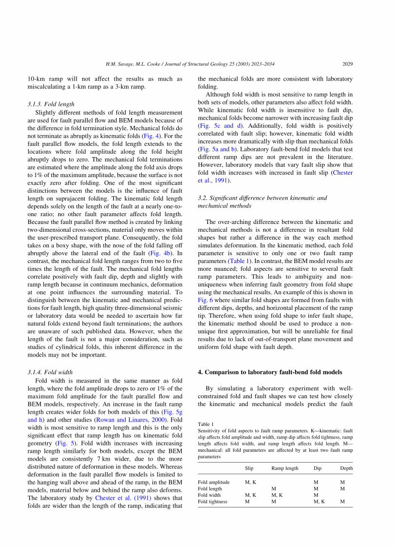
Table 1
Sensitivity of fold aspects to fault ramp parameters. K—kinematic: faultslip affects fold amplitude and width, ramp dip affects fold tightness, ramp
length affects fold width, and ramp length affects fold length. M—
mechanical: all fold parameters are affected by at least two fault ramp
parameters
Slip Ramp length Dip Depth
Fold amplitude M, K M M
Fold length M M MFold width M, K M, K M
Fold tightness M M M, K M
H.M. Savage, M.L. Cooke / Journal of Structural Geology 25 (2003) 2023–2034 2029
geometry from the fold shape. Because of the lack of out-of-transport plane movement in the kinematic method, wechose a non-plunging fold experiment, where stretching inthe third dimension is not a factor.
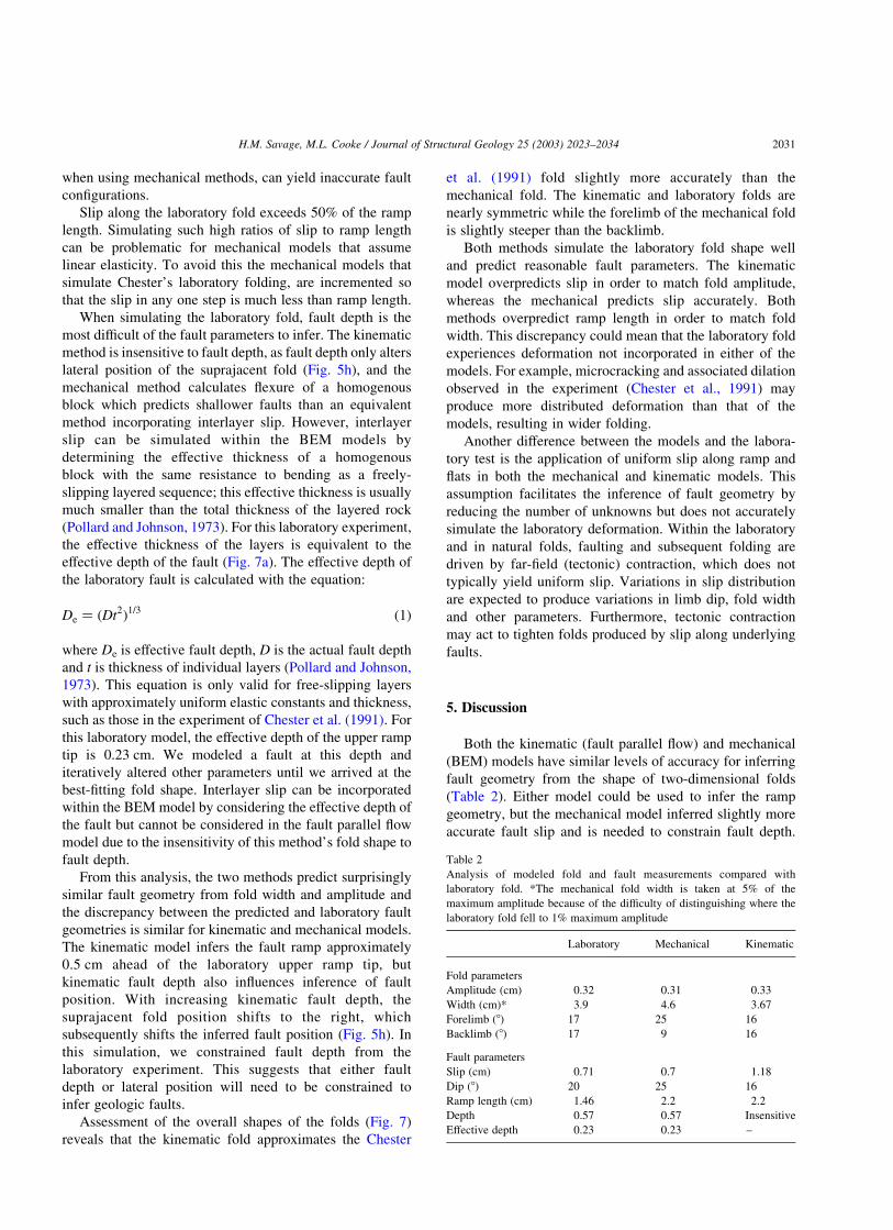
Chester et al. (1991) produced fault-bend folds bycompressing rock layers situated over a fault in a triaxialcompressor (Fig. 7a). The folded layers were limestoneinterbedded with either mica or lead to promote interlayerslip. During interlayer slip, weak contacts in a stack oflayered rock act as fault surfaces as the rock is folded,allowing greater bending than a homogenous body of thesame thickness and creating a higher, tighter fold (Pollardand Johnson, 1973). Experimental interlayer slip along micaor lead layers simulates geologic slip along layers with low
shear strength such as shale. A forcing block of sandstonewith a pre-existing, lubricated fault surface was used to foldthe limestone and mica layers. A rigid block of either graniteor sandstone composed the footwall of the fault to simulatethin-skinned deformation. The fault ramp is approximately0.57 cm deep, dipping 208, 1.53 cm long and, in theparticular experiment simulated here (Chester et al., 1991;Fig. 7a), the fault has approximately 0.71 cm of slip. Theresultant fold is 0.32 cm in amplitude, 3.9 cm wide, with aforelimb angle of about 178 and a 178 dipping backlimb(Fig. 7a).
A series of fault parallel flow and BEM models wereiteratively altered until the model fold shapes approximatedthe laboratory fold shape (Fig. 7a). The fault geometry ofthe laboratory experiment served as the initial modelconfiguration in this iterative process. Once a match ismade to the fold shape, the model faults are compared withthe laboratory fault geometry to determine which methodcould more accurately determine fault geometry from foldshape. Although the mechanical models could yieldmultiple fault configurations that produce fold shapesmatching the laboratory fold, we limit the chance ofspurious matches by using the laboratory geometry as theinitial model configuration. In the absence of data toconstrain a hypothetical initial geometry, the iterativematching of fold shape can become time consuming and,
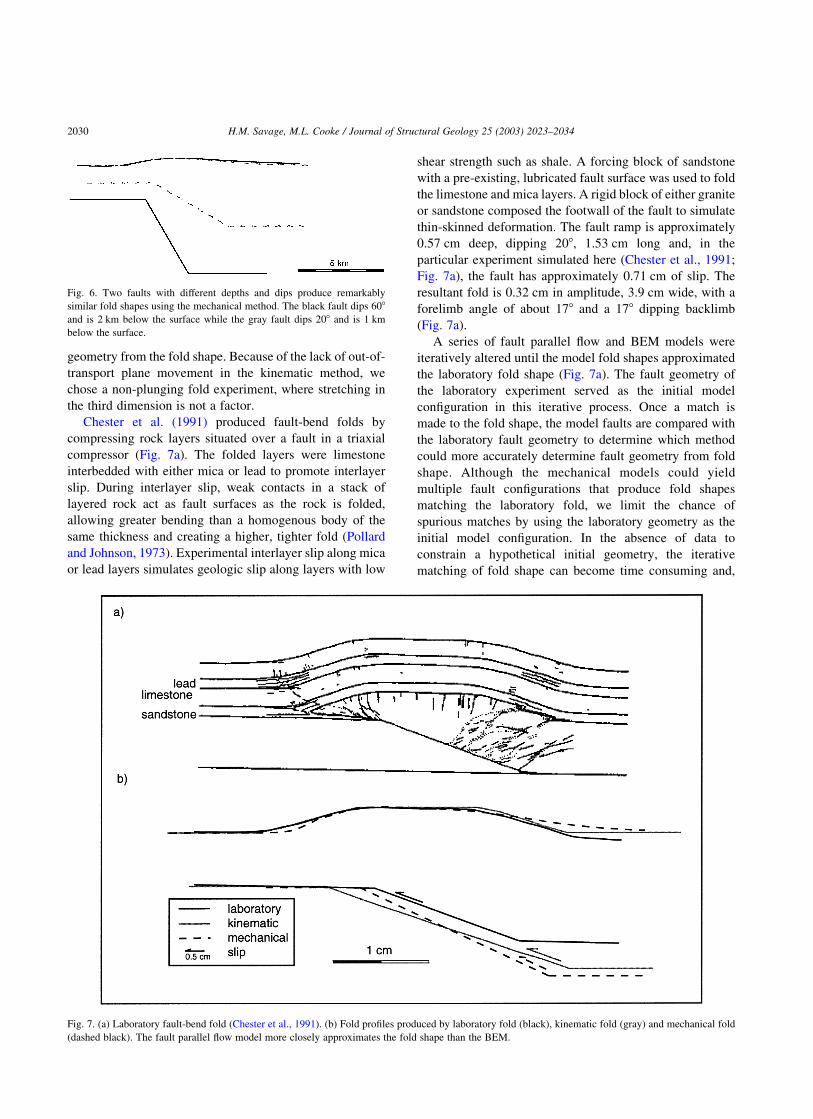
Fig. 6. Two faults with different depths and dips produce remarkablysimilar fold shapes using the mechanical method. The black fault dips 608and is 2 km below the surface while the gray fault dips 208 and is 1 km
below the surface.
Fig. 7. (a) Laboratory fault-bend fold (Chester et al., 1991). (b) Fold profiles produced by laboratory fold (black), kinematic fold (gray) and mechanical fold
(dashed black). The fault parallel flow model more closely approximates the fold shape than the BEM.
H.M. Savage, M.L. Cooke / Journal of Structural Geology 25 (2003) 2023–20342030
when using mechanical methods, can yield inaccurate faultconfigurations.
Slip along the laboratory fold exceeds 50% of the ramplength. Simulating such high ratios of slip to ramp lengthcan be problematic for mechanical models that assumelinear elasticity. To avoid this the mechanical models thatsimulate Chester’s laboratory folding, are incremented sothat the slip in any one step is much less than ramp length.
When simulating the laboratory fold, fault depth is themost difficult of the fault parameters to infer. The kinematicmethod is insensitive to fault depth, as fault depth only alterslateral position of the suprajacent fold (Fig. 5h), and themechanical method calculates flexure of a homogenousblock which predicts shallower faults than an equivalentmethod incorporating interlayer slip. However, interlayerslip can be simulated within the BEM models bydetermining the effective thickness of a homogenousblock with the same resistance to bending as a freely-slipping layered sequence; this effective thickness is usuallymuch smaller than the total thickness of the layered rock(Pollard and Johnson, 1973). For this laboratory experiment,the effective thickness of the layers is equivalent to theeffective depth of the fault (Fig. 7a). The effective depth ofthe laboratory fault is calculated with the equation:
De " #Dt2$1=3 #1$
where De is effective fault depth, D is the actual fault depthand t is thickness of individual layers (Pollard and Johnson,1973). This equation is only valid for free-slipping layerswith approximately uniform elastic constants and thickness,such as those in the experiment of Chester et al. (1991). Forthis laboratory model, the effective depth of the upper ramptip is 0.23 cm. We modeled a fault at this depth anditeratively altered other parameters until we arrived at thebest-fitting fold shape. Interlayer slip can be incorporatedwithin the BEM model by considering the effective depth ofthe fault but cannot be considered in the fault parallel flowmodel due to the insensitivity of this method’s fold shape tofault depth.
From this analysis, the two methods predict surprisinglysimilar fault geometry from fold width and amplitude andthe discrepancy between the predicted and laboratory faultgeometries is similar for kinematic and mechanical models.The kinematic model infers the fault ramp approximately0.5 cm ahead of the laboratory upper ramp tip, butkinematic fault depth also influences inference of faultposition. With increasing kinematic fault depth, thesuprajacent fold position shifts to the right, whichsubsequently shifts the inferred fault position (Fig. 5h). Inthis simulation, we constrained fault depth from thelaboratory experiment. This suggests that either faultdepth or lateral position will need to be constrained toinfer geologic faults.
Assessment of the overall shapes of the folds (Fig. 7)reveals that the kinematic fold approximates the Chester
et al. (1991) fold slightly more accurately than themechanical fold. The kinematic and laboratory folds arenearly symmetric while the forelimb of the mechanical foldis slightly steeper than the backlimb.
Both methods simulate the laboratory fold shape welland predict reasonable fault parameters. The kinematicmodel overpredicts slip in order to match fold amplitude,whereas the mechanical predicts slip accurately. Bothmethods overpredict ramp length in order to match foldwidth. This discrepancy could mean that the laboratory foldexperiences deformation not incorporated in either of themodels. For example, microcracking and associated dilationobserved in the experiment (Chester et al., 1991) mayproduce more distributed deformation than that of themodels, resulting in wider folding.
Another difference between the models and the labora-tory test is the application of uniform slip along ramp andflats in both the mechanical and kinematic models. Thisassumption facilitates the inference of fault geometry byreducing the number of unknowns but does not accuratelysimulate the laboratory deformation. Within the laboratoryand in natural folds, faulting and subsequent folding aredriven by far-field (tectonic) contraction, which does nottypically yield uniform slip. Variations in slip distributionare expected to produce variations in limb dip, fold widthand other parameters. Furthermore, tectonic contractionmay act to tighten folds produced by slip along underlyingfaults.
5. Discussion
Both the kinematic (fault parallel flow) and mechanical(BEM) models have similar levels of accuracy for inferringfault geometry from the shape of two-dimensional folds(Table 2). Either model could be used to infer the rampgeometry, but the mechanical model inferred slightly moreaccurate fault slip and is needed to constrain fault depth.
Table 2
Analysis of modeled fold and fault measurements compared withlaboratory fold. *The mechanical fold width is taken at 5% of the
maximum amplitude because of the difficulty of distinguishing where the
laboratory fold fell to 1% maximum amplitude
Laboratory Mechanical Kinematic
Fold parameters
Amplitude (cm) 0.32 0.31 0.33
Width (cm)* 3.9 4.6 3.67Forelimb (8) 17 25 16
Backlimb (8) 17 9 16
Fault parameters
Slip (cm) 0.71 0.7 1.18
Dip (8) 20 25 16
Ramp length (cm) 1.46 2.2 2.2Depth 0.57 0.57 Insensitive
Effective depth 0.23 0.23 –
H.M. Savage, M.L. Cooke / Journal of Structural Geology 25 (2003) 2023–2034 2031
However, in the unlikely scenario that the lateral position offault ramp is known and depth is unknown, the kinematicmethod can constrain ramp depth. Both models over-estimate the ramp length needed to simulate the laboratoryfold. For constraining fault length along fold axis, furtherthree-dimensional laboratory analysis is needed.
The one-to-one relationship of fault and fold parametersfor the kinematic method lent ease inferring fault geometryfrom the Chester et al. (1991) laboratory fold. In contrast,the interactive nature of the fault and fold parameters in themechanical model leads to non-uniqueness of fold shape,i.e. more than one fault geometry may produce the samefold shape. Because the fault shape of the Chester et al.(1991) experiment was our first guess, the iterativematching converged on a fault geometry similar to thelaboratory fault. A drastically different first-guess faultcould have resulted in iterative convergence on a very
different mechanical fault geometry that also matches thelaboratory fold shape.
To resolve this non-uniqueness, more than onemethod can be used. When out-of-transport-planedeformation is not a significant factor, the fault parallelflow kinematic method would provide a good firstapproximation. However the suitability of this methoddecreases for plunging folds or in areas where multiplefaults interact. In areas of significant three-dimensionaldeformation or in areas of multiple coeval faults, thekinematic model should not be taken as a finalapproximation. Furthermore, the limits of the kinematicmethod to constrain fault depth provides the need for anadditional method in any circumstance.
A drawback to directly inferring fault geometry from theshape of folded sedimentary layers with the mechanicalmodel is the lack of implicit interlayer slip. However, this
Fig. A1. Fold shape variation shown graphically (a–p). The kinematic models are shown in gray and the mechanical models in black. Fig. 4g shows a dark gray
trend that signifies the effect of fault dip on fold amplitude when height of the fold and depth of the syncline are both considered.
H.M. Savage, M.L. Cooke / Journal of Structural Geology 25 (2003) 2023–20342032
can be remedied by implementing the effective thickness ofthe strata into the model.
6. Conclusions
Detailed comparison of kinematic and mechanicalforward-modeled fold shapes highlight inherent differencesbetween the two methods. Kinematic fold parametersgenerally respond to changes in one fault parameter whilethe interplay between mechanical fold and fault parametersrenders non-unique inferences of fault geometry from foldshape. Consequently, a multi-proxy approach, incorporatingfield data and constraints from other types of models, issuggested. Both methods simulate fault/fold relationshipsrelatively well and when used in conjunction, offer apowerful tool for predicting fault geometry from fold shape.
Acknowledgements
We thank Kaj Johnson and an anonymous reviewer forinsightful comments that greatly improved this paper. Wealso thank Chris Okubo for reading a very early draft of thispaper. Fault parallel flow analysis was performed with3DMOVE software by Midland Valley Exploration, Ltd.Figure 1 was drafted by Tye Numelin.
Appendix A
Fig. A1
References
Allmendinger, R., Shaw, J., 2000. Estimation of fault propagation distance
from fold shape; implications for earthquake hazard assessment.
Geology 28 (12), 1099–1102.
Berger, P., Johnson, A.M., 1980. First-order analysis of deformation of a
thrust sheet moving over a ramp. Tectonophysics 70, T9–T24.
Chester, J.S., Logan, J.M., Spang, J.H., 1988. Comparison of thrust models
to basement-cored folds in the Rocky Mountain foreland. In: Schmidt,
C.J., Perry, W.J., Jr. (Eds.), Interaction of the Rocky Mountain Foreland
and the Cordilleran Thrust Belt. Geological Society of America Memoir
171, pp. 65–74.
Chester, J.S., Logan, J.M., Spang, J.H., 1991. Influence of layering and
boundary conditions on fault-bend and fault-propagation folding.
Geological Society of America Bulletin 103 (8), 1059–1072.
Comninou, M., Dundurs, J., 1975. The angular dislocation in a half-space.
Journal of Elasticity 5, 205–216.
Cooke, M., Pollard, D.D., 1997. Bedding-plane slip in initial stages of fault-
related folding. Journal of Structural Geology 19, 567–581.
Crider, J.G., Pollard, D.D., 1998. Fault linkage: 3D mechanical interaction
between echelon normal faults. Journal of Geophysical Research 103,
24373–24391.
Dahlstrom, C.A., 1990. Geometric constraints derived from the law of
conservation of volume and applied to evolutionary models for
detachment folding. AAPG Bulletin 74 (3), 336–344.
Davis, G.H., 1978. The monocline fold pattern of the Colorado Plateau. In:
Matthews, V. (Ed.), Laramide Folding Associated with Basement Block
Faulting in the Western United States. Geological Society of America
Memoir 151, pp. 215–233.
Fung, Y.C., 1969. A First Course in Continuum Mechanics, Prentice-Hall,
Englewood Cliffs, NJ.
Geiser, J., Geiser, P.A., Kligfield, R., Ratliff, R., Rowan, M., 1988. New
applications of computer-based section construction: Strain analysis,
local balancing and subsurface fault prediction. The Mountain
Geologists 25(2), 47–59.
Johnson, K., Johnson, A., 2001. Mechanical analysis of the geometry of
forced-folds. Journal of Structural Geology 24, 401–410.
Kane, S.J., Williams, G.D., Buddin, T.S., 2003. A generalised flow
approach to section restoration—fault bend folding. In preparation.
Kattenhorn, S.A., Pollard, D.D., 2001. Integrating 3-D seismic data, field
analogs, and mechanical models in the analysis of segmented normal
faults in the Wytch Farm oil field, southern England, United Kingdom.
American Association of Petroleum Geologists Bulletin 85 (7),
1183–1210.
Keetley, J.T., Hill, K.C., 2000. 3D structural modeling of the Kutubu oil
fields, PNG. In: AAPG International Conference and Exhibition;
Abstracts 84. American Association of Petroleum Geologists, 1446.
Kerr, H.G., White, N., 1992. Laboratory testing of an automatic method for
determining normal fault geometry at depth. Journal of Structural
Geology 14, 873–885.
Kerr, H.G., White, N., 1994. Application of an automatic method for
determining normal fault geometries. Journal of Structural Geology 16,
1691–1709.
Kilsdonk, B., Fletcher, R.C., 1989. An analytical model of hanging-wall
and footwall deformation at ramps on normal and thrust faults.
Tectonophysics 163, 153–168.
Maerten, L., 1999. Mechanical interaction of intersecting normal faults:
theory, field examples and applications. Ph.D. Thesis, Stanford
University.
Maerten, L., Willemse, E.J.M., Pollard, D.D., Rawnsley, K., 1999. Slip
distributions on intersecting normal faults. Journal of Structural
Geology 21, 259–271.
Maerten, L., Pollard, D.D., Karpuz, R., 2000. How to constrain 3-D fault
continuity and linkage using reflection seismic data: a geomechanical
approach. American Association of Petroleum Geologists Bulletin 84,
1311–1324.
Maerten, L., Gillespie, P., Pollard, D.D., 2001. Effect of local stress
perturbation on secondary fault development. Journal of Structural
Geology 24, 145–153.
Means, W.D., 1976. Stress and Strain, Springer-Verlag, New York.
Mitra, G., Sussman, A.J., 1997. Structural evolution of connecting splay
duplexes and their implications for critical taper: an example based on
geometry and kinematics of the Canyon Range culmination, Sevier
Belt, central Utah. Journal of Structural Geology 19 (3-4), 503–522.
Morse, J., 1977. Deformation in the Ramp Regions of Overthrust Faults;
Experiments with Small-scale, Rock Models, Wyoming Geological
Association, Casper, WY.
Pollard, D.D., Johnson, A.M., 1973. Mechanics of growth of some
laccolithic intrusions in the Henry Mountains, Utah; II, Bending and
failure of overburden layers and sill formation. Tectonophysics 18 (3-
4), 311–354.
Rich, J.L., 1934. Mechanics of low-angle overthrusting as illustrated by
Cumberland thrust block, Virginia, Kentucky and Tennessee. Bulletin
of the American Association of Petroleum Geologists 18 (12),
1584–1596.
Rowan, M.G., Linares, R., 2000. Fold-evolution matrices and axial-
surfaces of fault-bend folds; application to the Medina Anticline,
Eastern Cordillera, Columbia. AAPG Bulletin 84 (6), 741–764.
Salvini, F., Storti, F., 2001. The distribution of deformation in parallel fault-
related folds with migrating axial surfaces: comparison between fault-
propagation and fault-bend folding. Journal of Structural Geology 23,
25–32.
H.M. Savage, M.L. Cooke / Journal of Structural Geology 25 (2003) 2023–2034 2033
Sanderson, D.J., 1982. Models of strain variation in nappes and thrustsheets; a review. Tectonophysics 88 (3-4), 201–233.
Strayer, L.M., Hudleston, P.J., 1997. Numerical modeling of fold initiation
at thrust ramps. Journal of Structural Geology 19 (3-4), 551–566.
Suppe, J., 1983. Geometry and kinematics of fault-bend folding. AmericanJournal of Science 283 (7), 684–721.
Thomas, A.L., 1994. POLY3D: A Three-Dimensional, Polygonal Element,
Displacement Discontinuity Boundary Element Computer Programwith Applications to Fractures, Faults and Cavities in the Earth’s Crust.
Ph.D. thesis, Stanford University.
Timoshenko, S.P., Goodier, J.N., 1934. Theory of Elasticity, McGraw-Hill
Book Company, New York.Wilkerson, M.S., Medwedeff, D.A., Marshak, S., 1991. Geometrical
modeling of fault-related folds: a pseudo-three-dimensional approach.
Journal of Structural Geology 13, 801–812.
Wilkerson, M.S., Apotria, T., Farid, T., 2002. Intrepreting the geologic map
expression of contractional fault-related fold terminations: lateral/
oblique ramps versus displacement gradients. Journal of Structural
Geology 24, 593–607.
Willemse, E.J.M., Pollard, D.D., Aydin, A., 1996. Three-dimensional
analyses of slip distributions on normal fault arrays with consequences
for fault scaling. Journal of Structural Geology 18 (2/3), 295–309.
Williams, G., Vann, I., 1987. The geometry of listric normal faults and
deformation in their hanging walls. Journal of Structural Geology 9,
789–795.
Withjack, M.O., Peterson, E.T., 1993. Prediction of normal-fault
geometries—a sensitivity analysis. AAPG Bulletin 77 (11),
1860–1873.
H.M. Savage, M.L. Cooke / Journal of Structural Geology 25 (2003) 2023–20342034