Embed Size (px)
Citation preview
LP SOLIDSTART LVLBEAM & HEADERCANADIAN (LSD) TECHNICAL GUIDE
2.0E
Limit States Design
2
Introduction
IMPORTANT NOTES1. LP SolidStart LVL shall be designed for dry-use conditions only. Dry-use applies to
products installed in dry, covered and well ventilated interior conditions in which the equivalent average moisture content in lumber will not exceed 15% nor a maximum of 19%.
2. This guide is valid only for LP SolidStart LVL members supporting loads applied parallel to the face of the veneer (“edge” orientation).
3. The tables in this guide meet the design requirements of the National Building Code of Canada for Limit States Design and assume a normal importance category. Ensure that the specified design loads, duration of load increases and deflection limits that you use to select products from this guide are appropriate for your application and comply with local code requirements. If you do not know the correct design criteria and all the loads imposed on the component from all parts of the structure, seek qualified help from the architect, engineer or designer of the structure. Additional reference data on wood construction is available in the form of building codes, code evaluation reports and other design references.
4. The Quick Reference and Uniform Load Resistance (PLF) tables in this guide are only for uniform loads on simple (single) or equal, continuous (multiple)span members as noted in each table. For other conditions such as concentrated loads, unequal spans, etc., contact your LP SolidStart distributor.
5. Beam spans in this guide are typically measured from center-to-center of supports except for door and window headers. A structurally adequate bearing surface under the full width (thickness) of the member must be provided at each support.
6. Minimum bearing length is 1-1/2" (at least one jack stud or cripple is required unless otherwise noted for a specific table. Refer to the Factored Reaction Resistance chart and the notes for each table. Verify local code requirements for minimum bearing.
7. Total load deflections are based on instantaneous loading. Long term deflection (creep) under sustained load has not been considered.
8. Vibration has not been considered in this guide. If LP SolidStart LVL is used asa floor joist, the designer shall perform the required vibration control checks.
9. LP SolidStart LVL is not cambered.
10. Higher grades of LP SolidStart LVL can be substituted for the indicated grade.
11. LP SolidStart LVL sized with the tables and design values in this guide requires continuous lateral restraint of the compression edge. Continuous restraint is defined as a maximum unbraced length of 24". This restraint is normally provided by sheathing and/or other framing members, which shall be adequately anchored to the LVL and the supporting structure. Framing conditions that do not provide continuous lateral restraint require special design. Contact your LP SolidStart Engineered Wood Products distributor. Caution: Failure to provide adequate lateral restraint could result in an unstable member and reduce its load capacity.
12. Lateral restraint shall also be provided at all supports to prevent rotation or twisting.
13. Refer to the Connection Details page for information on designing nailed and bolted connections, minimum nail spacing and end distances, and for properly connecting multiple plies of LVL to form a built-up member.
LP® SolidStart® Laminated Veneer Lumber (LVL) is a vast improvement over traditional lumber. Problems that naturally occur as sawn lumber dries — twisting, splitting, checking, crowning and warping — are greatly reduced.
THE STRENGTH IS IN THE ENGINEERINGLP SolidStart LVL is made from ultrasonically and visually graded
veneers arranged in a specific pattern to maximize the strength and stiffness of the veneers and to disperse the naturally occurring characteristics of wood, such as knots, that can weaken a sawn lumber beam. The veneers are then bonded with waterproof adhesives under pressure and heat. LP SolidStart LVL beams are exceptionally strong, solid and straight, making them excellent for most primary load-carrying beam applications.
LP SolidStart LVL: AVAILABLE GRADES AND SIZESLP SolidStart LVL is available in a range of depths and lengths, and
is available in standard thicknesses of 1-3/4" and 3-1/2". The 2.0E LVL is also available in factory-laminated thicknesses (known as “billet beam”) of 5-1/4" and 7" to eliminate the need for field nailing and/or bolting of multiple plies. In addition, a water-resistant coating called SiteCote™ is available for extra weather protection during construction. Please verify availability with the LP SolidStart Engineered Wood Products distributor in your area before specifying these products.
LIFETIME LIMITED WARRANTYLP SolidStart Engineered Wood Products are backed by a lifetime
limited warranty. Visit LPCorp.com or call 1.888.820.0325 for a copy of the warranty.
Designed to Outperform Traditional LumberSOFTWARE FOR EASY, RELIABLE DESIGN
Our design/specification software enhances your in-house design capabilities. It offers accurate designs for a wide variety of applications with interfaces for printed output or plotted drawings. Through our distributors, we offer component design review services for designs using LP SolidStart Engineered Wood Products.
CODE EVALUATION LP SolidStart Laminated Veneer Lumber has been evaluated by
CCMC for compliance with the National Building Code of Canada. Contact your local LP SolidStart Engineered Wood Products distributor or visit LPCorp.com for the most current code reports.
§ CCMC Evaluation Report 11518-R§ APA Product Report® PR-L280C
SUSTAINABLELP Building Products uses logs from SFI® certified forest
manage ment and fiber sourcing systems to help ensure that our entire wood supply comes from well managed forests and non-controversial sources. Virtually the entire log is used in the manufacturing process, and wood waste is repurposed or used to help fuel our mills. LP Engineered Wood Products also reduce construction waste on the job site.
3
Table of Contents
2.0E LVL
Product Specifications & Design Values . . . . . . . . . . . . 4
Quick Reference Tables:
Floor Loading . . . . . . . . . . . . . . . . . . . . . . . . . 5
Combined Roof and Floor Loading . . . . . . . . . . . . . . 6–7
Roof Loading . . . . . . . . . . . . . . . . . . . . . . . . . 8–9
Uniform Floor Load (PLF) Resistance Tables . . . . . . . . . . 10
Uniform Roof Load (PLF) Resistance Tables . . . . . . . . . . . 11
GENERAL INFORMATION
Temporary Bracing & Warnings . . . . . . . . . . . . . . . . . . 12
Installation Details . . . . . . . . . . . . . . . . . . . . . . . . . 13
Connection of Multiple Ply Beams . . . . . . . . . . . . . . . . 14
Fastener Design and Fastener & Load Orientation . . . . . . . 15
Handling & Storage Guidelines . . . . . . . . . . . . . . . . . . 16
4
Product Specifications & Design Values
SPECIFIED STRENGTHS & STIFFNESS (PSI)
Grade Bending fb
4
Modulus of Elasticity E5
(x106 PSI)
Shear fv
Compression
fc (Parallel To Grain)
fcp (Perpendicular To Grain)
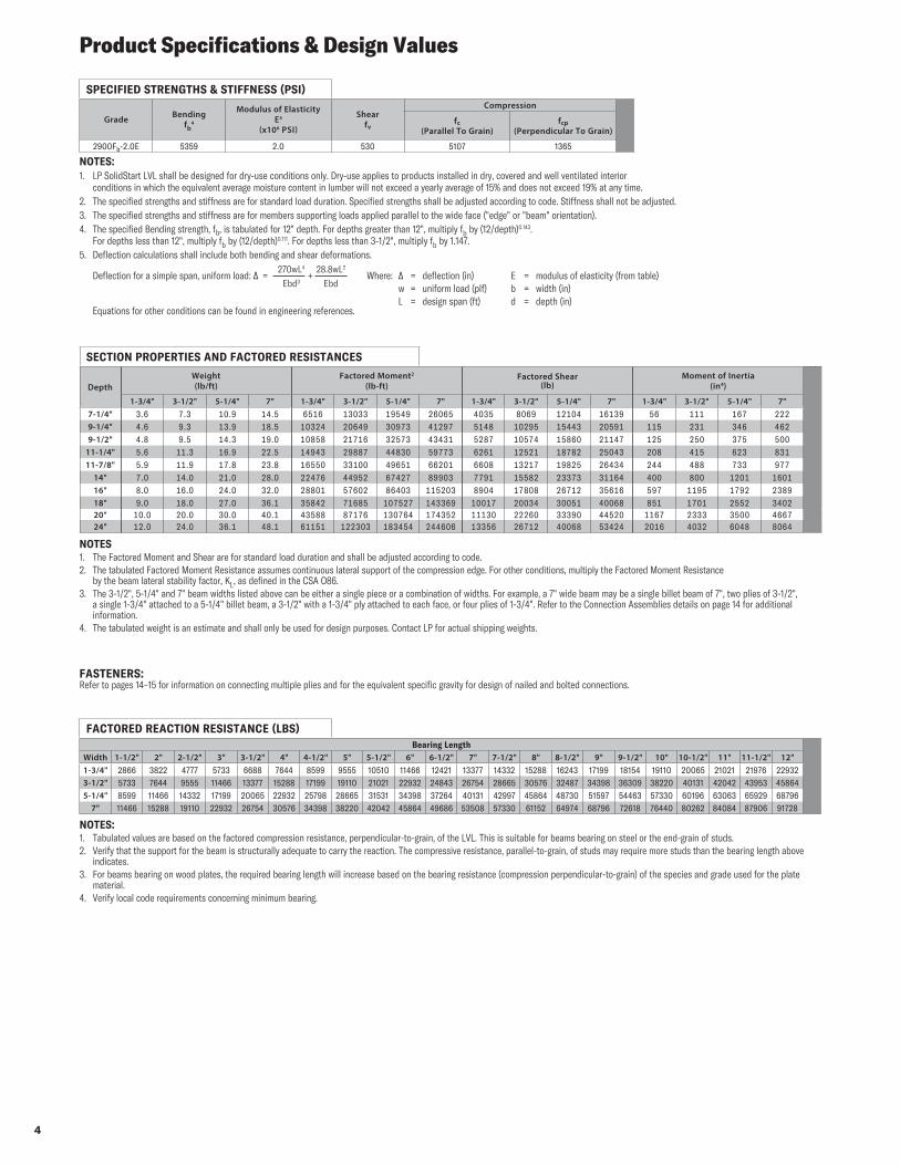
2900Fb-2.0E 5359 2.0 530 5107 1365
FACTORED REACTION RESISTANCE (LBS)Bearing Length
Width 1-1/2" 2" 2-1/2" 3" 3-1/2" 4" 4-1/2" 5" 5-1/2" 6" 6-1/2" 7" 7-1/2" 8" 8-1/2" 9" 9-1/2" 10" 10-1/2" 11" 11-1/2" 12"1-3/4" 2866 3822 4777 5733 6688 7644 8599 9555 10510 11466 12421 13377 14332 15288 16243 17199 18154 19110 20065 21021 21976 229323-1/2" 5733 7644 9555 11466 13377 15288 17199 19110 21021 22932 24843 26754 28665 30576 32487 34398 36309 38220 40131 42042 43953 458645-1/4" 8599 11466 14332 17199 20065 22932 25798 28665 31531 34398 37264 40131 42997 45864 48730 51597 54463 57330 60196 63063 65929 68796
7" 11466 15288 19110 22932 26754 30576 34398 38220 42042 45864 49686 53508 57330 61152 64974 68796 72618 76440 80262 84084 87906 91728
NOTES: 1. Tabulated values are based on the factored compression resistance, perpendicular-to-grain, of the LVL. This is suitable for beams bearing on steel or the end-grain of studs.2. Verify that the support for the beam is structurally adequate to carry the reaction. The compressive resistance, parallel-to-grain, of studs may require more studs than the bearing length above
indicates.3. For beams bearing on wood plates, the required bearing length will increase based on the bearing resistance (compression perpendicular-to-grain) of the species and grade used for the plate
material.4. Verify local code requirements concerning minimum bearing.
SECTION PROPERTIES AND FACTORED RESISTANCES
DepthWeight (lb/ft)
Factored Moment2 (lb-ft)
Factored Shear (lb)
Moment of Inertia (in4)
1-3/4" 3-1/2" 5-1/4" 7" 1-3/4" 3-1/2" 5-1/4" 7" 1-3/4" 3-1/2" 5-1/4" 7" 1-3/4" 3-1/2" 5-1/4" 7"7-1/4" 3.6 7.3 10.9 14.5 6516 13033 19549 26065 4035 8069 12104 16139 56 111 167 2229-1/4" 4.6 9.3 13.9 18.5 10324 20649 30973 41297 5148 10295 15443 20591 115 231 346 4629-1/2" 4.8 9.5 14.3 19.0 10858 21716 32573 43431 5287 10574 15860 21147 125 250 375 500
11-1/4" 5.6 11.3 16.9 22.5 14943 29887 44830 59773 6261 12521 18782 25043 208 415 623 83111-7/8" 5.9 11.9 17.8 23.8 16550 33100 49651 66201 6608 13217 19825 26434 244 488 733 977
14" 7.0 14.0 21.0 28.0 22476 44952 67427 89903 7791 15582 23373 31164 400 800 1201 160116" 8.0 16.0 24.0 32.0 28801 57602 86403 115203 8904 17808 26712 35616 597 1195 1792 238918" 9.0 18.0 27.0 36.1 35842 71685 107527 143369 10017 20034 30051 40068 851 1701 2552 340220" 10.0 20.0 30.0 40.1 43588 87176 130764 174352 11130 22260 33390 44520 1167 2333 3500 466724" 12.0 24.0 36.1 48.1 61151 122303 183454 244606 13356 26712 40068 53424 2016 4032 6048 8064
NOTES1. The Factored Moment and Shear are for standard load duration and shall be adjusted according to code.2. The tabulated Factored Moment Resistance assumes continuous lateral support of the compression edge. For other conditions, multiply the Factored Moment Resistance
by the beam lateral stability factor, KL, as defined in the CSA O86.3. The 3-1/2", 5-1/4" and 7" beam widths listed above can be either a single piece or a combination of widths. For example, a 7" wide beam may be a single billet beam of 7", two plies of 3-1/2",
a single 1-3/4" attached to a 5-1/4" billet beam, a 3-1/2" with a 1-3/4" ply attached to each face, or four plies of 1-3/4". Refer to the Connection Assemblies details on page 14 for additional information.
4. The tabulated weight is an estimate and shall only be used for design purposes. Contact LP for actual shipping weights.
FASTENERS:Refer to pages 14–15 for information on connecting multiple plies and for the equivalent specific gravity for design of nailed and bolted connections.
NOTES:1. LP SolidStart LVL shall be designed for dry-use conditions only. Dry-use applies to products installed in dry, covered and well ventilated interior
conditions in which the equivalent average moisture content in lumber will not exceed a yearly average of 15% and does not exceed 19% at any time.2. The specified strengths and stiffness are for standard load duration. Specified strengths shall be adjusted according to code. Stiffness shall not be adjusted.3. The specified strengths and stiffness are for members supporting loads applied parallel to the wide face ("edge" or "beam" orientation).4. The specified Bending strength, fb, is tabulated for 12" depth. For depths greater than 12", multiply fb by (12/depth)0.143.
For depths less than 12", multiply fb by (12/depth)0.111. For depths less than 3-1/2", multiply fb by 1.147.5. Deflection calculations shall include both bending and shear deformations.
Deflection for a simple span, uniform load: ∆ = + Where: ∆ = deflection (in) E = modulus of elasticity (from table) w = uniform load (plf) b = width (in) L = design span (ft) d = depth (in) Equations for other conditions can be found in engineering references.
270wL4 28.8wL2
Ebd3 Ebd
5
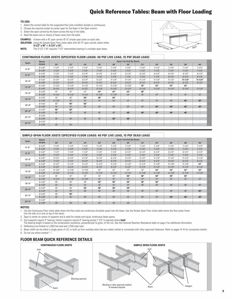
Quick Reference Tables: Beam with Floor Loading
NOTES:1. Use the Continuous Floor Joists table where the floor joists are continuous (multiple span) over the beam. Use the Simple-Span Floor Joists table where the floor joists frame
into the side of or end on top of the beam.2. Span is center-to-center of supports and is valid for simple and equal, continuous beam spans.3. End supports require 3" bearing. Interior supports require 6" bearing except 7-1/2" is required where bold.
The bearing length is based on the compressive resistance, perpendicular-to-grain, of the LVL. See the Factored Reaction Resistance table on page 4 for additional information.4. Deflections are limited to L/360 live load and L/240 total load.5. Beam width can be either a single piece of LVL or built up from multiple plies that are nailed, bolted or connected with other approved fasteners. Refer to pages 14-15 for connection details.6. Do not use where marked “-”.
TO USE:1. Select the correct table for the supported floor joist condition (simple or continuous).2. Choose the required center-to-center span for the beam in the Span column.3. Select the span carried by the beam across the top of the table.4. Read the beam size or choice of beam sizes from the table.
EXAMPLE: A beam with a 16' span carries 15'-0" simple span joists on each side.SOLUTION: Using the Simple-Span Floor Joists table with 30'-0" span carried, select either
3-1/2" x 16" or 5-1/4" x 14".NOTE: The 3-1/2" x 16" requires 7-1/2" intermediate bearing if a multiple span beam.
CONTINUOUS FLOOR JOISTS (SPECIFIED FLOOR LOADS: 40 PSF LIVE LOAD, 15 PSF DEAD LOAD)
Span Beam Width
Span Carried By Beam20' 22' 24' 26' 28' 30' 32' 34' 36' 38' 40'
6'-0"3-1/2" 7-1/4" 7-1/4" 7-1/4" 7-1/4" 7-1/4" 7-1/4" 7-1/4" 7-1/4" 7-1/4" 7-1/4" 7-1/4"5-1/4" 7-1/4" 7-1/4" 7-1/4" 7-1/4" 7-1/4" 7-1/4" 7-1/4" 7-1/4" 7-1/4" 7-1/4" 7-1/4"
8'-0"3-1/2" 7-1/4" 7-1/4" 9-1/4" 9-1/4" 9-1/4" 9-1/4" 9-1/4" 9-1/4" 9-1/4" 9-1/4" 9-1/4"5-1/4" 7-1/4" 7-1/4" 7-1/4" 7-1/4" 7-1/4" 7-1/4" 7-1/4" 7-1/4" 9-1/4" 9-1/4" 9-1/4"
10'-0"3-1/2" 9-1/4" 9-1/4" 9-1/4" 9-1/2" 11-1/4" 11-1/4" 11-1/4" 11-1/4" 11-1/4" 11-1/4" 11-1/4"5-1/4" 9-1/4" 9-1/4" 9-1/4" 9-1/4" 9-1/4" 9-1/4" 9-1/4" 9-1/4" 9-1/4" 9-1/2" 9-1/2"
12'-0"3-1/2" 11-1/4" 11-1/4" 11-1/4" 11-1/4" 11-7/8" 11-7/8" 14" 14" 14" 14" -5-1/4" 9-1/4" 9-1/4" 9-1/2" 11-1/4" 11-1/4" 11-1/4" 11-1/4" 11-1/4" 11-1/4" 11-1/4" 11-1/4"
14'-0"3-1/2" 14" 14" 14" 14" 14" 14" 16" - - - -5-1/4" 11-1/4" 11-1/4" 11-1/4" 11-7/8" 11-7/8" 14" 14" 14" 14" 14" 14"
16'-0"3-1/2" 14" 16" 16" 16" 16" - - - - - -5-1/4" 11-7/8" 14" 14" 14" 14" 14" 14" 14" 16" 16" 16"
18'-0"3-1/2" 16" 16" 18" - - - - - - - -5-1/4" 14" 14" 16" 16" 16" 16" 16" 16" 16" 16" 18"
20'-0"3-1/2" 18" 18" - - - - - - - - -5-1/4" 16" 16" 16" 16" 18" 18" 18" 18" 18" 18" -
22'-0"3-1/2" - - - - - - - - - - -5-1/4" 18" 18" 18" 18" 18" 18" - - - - -
24'-0"3-1/2" - - - - - - - - - - -5-1/4" 18" 18" - - - - - - - - -
SIMPLE-SPAN FLOOR JOISTS (SPECIFIED FLOOR LOADS: 40 PSF LIVE LOAD, 15 PSF DEAD LOAD)
Span Beam Width
Span Carried By Beam20' 22' 24' 26' 28' 30' 32' 34' 36' 38' 40'
6'-0"3-1/2" 7-1/4" 7-1/4" 7-1/4" 7-1/4" 7-1/4" 7-1/4" 7-1/4" 7-1/4" 7-1/4" 7-1/4" 7-1/4"5-1/4" 7-1/4" 7-1/4" 7-1/4" 7-1/4" 7-1/4" 7-1/4" 7-1/4" 7-1/4" 7-1/4" 7-1/4" 7-1/4"
8'-0"3-1/2" 7-1/4" 7-1/4" 7-1/4" 7-1/4" 7-1/4" 9-1/4" 9-1/4" 9-1/4" 9-1/4" 9-1/4" 9-1/4"5-1/4" 7-1/4" 7-1/4" 7-1/4" 7-1/4" 7-1/4" 7-1/4" 7-1/4" 7-1/4" 7-1/4" 7-1/4" 7-1/4"
10'-0"3-1/2" 9-1/4" 9-1/4" 9-1/4" 9-1/4" 9-1/4" 9-1/4" 9-1/2" 11-1/4" 11-1/4" 11-1/4" 11-1/4"5-1/4" 7-1/4" 7-1/4" 9-1/4" 9-1/4" 9-1/4" 9-1/4" 9-1/4" 9-1/4" 9-1/4" 9-1/4" 9-1/4"
12'-0"3-1/2" 9-1/2" 11-1/4" 11-1/4" 11-1/4" 11-1/4" 11-1/4" 11-1/4" 11-7/8" 11-7/8" 11-7/8" 14"5-1/4" 9-1/4" 9-1/4" 9-1/4" 9-1/4" 9-1/2" 9-1/2" 11-1/4" 11-1/4" 11-1/4" 11-1/4" 11-1/4"
14'-0"3-1/2" 11-1/4" 11-7/8" 11-7/8" 14" 14" 14" 14" 14" 14" 14" 14"5-1/4" 11-1/4" 11-1/4" 11-1/4" 11-1/4" 11-1/4" 11-1/4" 11-7/8" 11-7/8" 11-7/8" 11-7/8" 11-7/8"
16'-0"3-1/2" 14" 14" 14" 14" 16" 16" 16" 16" 16" 16" -5-1/4" 11-1/4" 11-7/8" 11-7/8" 14" 14" 14" 14" 14" 14" 14" 14"
18'-0"3-1/2" 16" 16" 16" 16" 16" 16" 18" 18" - - -5-1/4" 14" 14" 14" 14" 14" 14" 16" 16" 16" 16" 16"
20'-0"3-1/2" 16" 18" 18" 18" 18" 18" - - - - -5-1/4" 14" 16" 16" 16" 16" 16" 16" 16" 16" 18" 18"
22'-0"3-1/2" 18" 18" - - - - - - - - -5-1/4" 16" 16" 16" 16" 18" 18" 18" 18" 18" 18" 18"
24'-0"3-1/2" - - - - - - - - - - -5-1/4" 18" 18" 18" 18" 18" 18" - - - - -
Span Carried Span
FLOOR BEAM QUICK REFERENCE DETAILS
Blocking or other approved method of restraint required Beam Hangers
Joist
CONTINUOUS FLOOR JOISTS SIMPLE-SPAN FLOOR JOISTS
Blocking optional
Joist
Beam
6
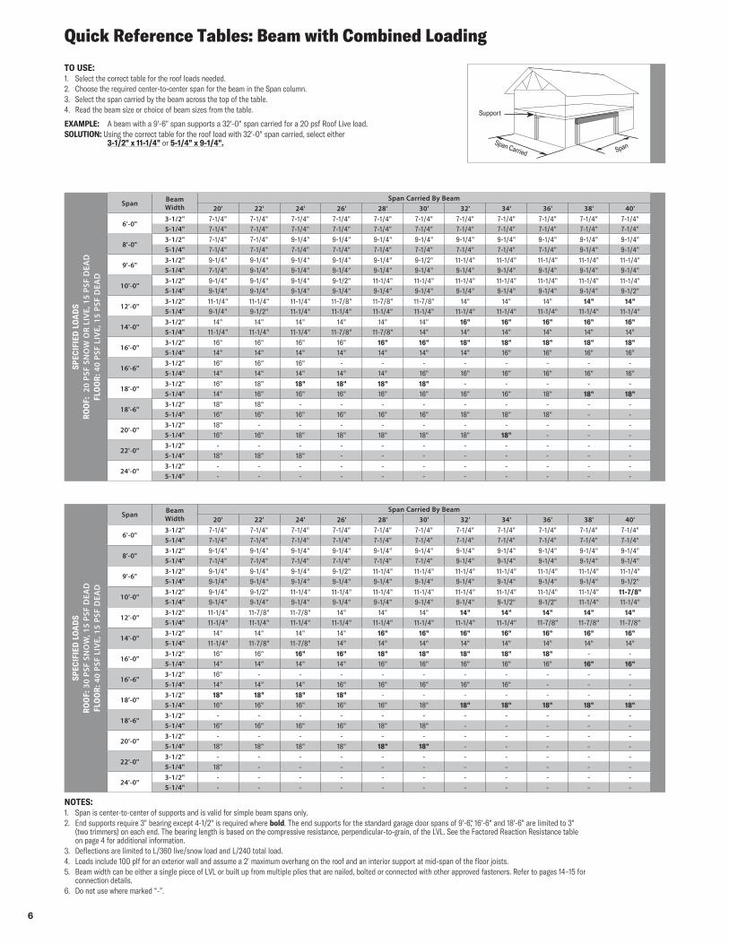
Quick Reference Tables: Beam with Combined Loading
TO USE:1. Select the correct table for the roof loads needed.2. Choose the required center-to-center span for the beam in the Span column.3. Select the span carried by the beam across the top of the table.4. Read the beam size or choice of beam sizes from the table.
EXAMPLE: A beam with a 9'-6" span supports a 32'-0" span carried for a 20 psf Roof Live load.SOLUTION: Using the correct table for the roof load with 32'-0" span carried, select either
3-1/2" x 11-1/4" or 5-1/4" x 9-1/4".
SPEC
IFIE
D L
OA
DS
RO
OF:
20
PSF
SNO
W O
R LI
VE,
15
PSF
DEA
DFL
OO
R: 4
0 PS
F LI
VE,
15
PSF
DEA
D
Span Beam Width
Span Carried By Beam20' 22' 24' 26' 28' 30' 32' 34' 36' 38' 40'
6'-0"3-1/2" 7-1/4" 7-1/4" 7-1/4" 7-1/4" 7-1/4" 7-1/4" 7-1/4" 7-1/4" 7-1/4" 7-1/4" 7-1/4"5-1/4" 7-1/4" 7-1/4" 7-1/4" 7-1/4" 7-1/4" 7-1/4" 7-1/4" 7-1/4" 7-1/4" 7-1/4" 7-1/4"
8'-0"3-1/2" 7-1/4" 7-1/4" 9-1/4" 9-1/4" 9-1/4" 9-1/4" 9-1/4" 9-1/4" 9-1/4" 9-1/4" 9-1/4"5-1/4" 7-1/4" 7-1/4" 7-1/4" 7-1/4" 7-1/4" 7-1/4" 7-1/4" 7-1/4" 7-1/4" 9-1/4" 9-1/4"
9'-6"3-1/2" 9-1/4" 9-1/4" 9-1/4" 9-1/4" 9-1/4" 9-1/2" 11-1/4" 11-1/4" 11-1/4" 11-1/4" 11-1/4"5-1/4" 7-1/4" 9-1/4" 9-1/4" 9-1/4" 9-1/4" 9-1/4" 9-1/4" 9-1/4" 9-1/4" 9-1/4" 9-1/4"
10'-0"3-1/2" 9-1/4" 9-1/4" 9-1/4" 9-1/2" 11-1/4" 11-1/4" 11-1/4" 11-1/4" 11-1/4" 11-1/4" 11-1/4"5-1/4" 9-1/4" 9-1/4" 9-1/4" 9-1/4" 9-1/4" 9-1/4" 9-1/4" 9-1/4" 9-1/4" 9-1/4" 9-1/2"
12'-0"3-1/2" 11-1/4" 11-1/4" 11-1/4" 11-7/8" 11-7/8" 11-7/8" 14" 14" 14" 14" 14"5-1/4" 9-1/4" 9-1/2" 11-1/4" 11-1/4" 11-1/4" 11-1/4" 11-1/4" 11-1/4" 11-1/4" 11-1/4" 11-1/4"
14'-0"3-1/2" 14" 14" 14" 14" 14" 14" 16" 16" 16" 16" 16"5-1/4" 11-1/4" 11-1/4" 11-1/4" 11-7/8" 11-7/8" 14" 14" 14" 14" 14" 14"
16'-0"3-1/2" 16" 16" 16" 16" 16" 16" 18" 18" 18" 18" 18"5-1/4" 14" 14" 14" 14" 14" 14" 14" 16" 16" 16" 16"
16'-6"3-1/2" 16" 16" 16" - - - - - - - -5-1/4" 14" 14" 14" 14" 14" 16" 16" 16" 16" 16" 16"
18'-0"3-1/2" 16" 18" 18" 18" 18" 18" - - - - -5-1/4" 14" 16" 16" 16" 16" 16" 16" 16" 18" 18" 18"
18'-6"3-1/2" 18" 18" - - - - - - - - -5-1/4" 16" 16" 16" 16" 16" 16" 18" 18" 18" - -
20'-0"3-1/2" 18" - - - - - - - - - -5-1/4" 16" 16" 18" 18" 18" 18" 18" 18" - - -
22'-0"3-1/2" - - - - - - - - - - -5-1/4" 18" 18" 18" - - - - - - - -
24'-0"3-1/2" - - - - - - - - - - -5-1/4" - - - - - - - - - - -
SPEC
IFIE
D L
OA
DS
RO
OF:
30
PSF
SNO
W, 1
5 PS
F D
EAD
FLO
OR
: 40
PSF
LIV
E, 1
5 PS
F D
EAD
Span Beam Width
Span Carried By Beam20' 22' 24' 26' 28' 30' 32' 34' 36' 38' 40'
6'-0"3-1/2" 7-1/4" 7-1/4" 7-1/4" 7-1/4" 7-1/4" 7-1/4" 7-1/4" 7-1/4" 7-1/4" 7-1/4" 7-1/4"5-1/4" 7-1/4" 7-1/4" 7-1/4" 7-1/4" 7-1/4" 7-1/4" 7-1/4" 7-1/4" 7-1/4" 7-1/4" 7-1/4"
8'-0"3-1/2" 9-1/4" 9-1/4" 9-1/4" 9-1/4" 9-1/4" 9-1/4" 9-1/4" 9-1/4" 9-1/4" 9-1/4" 9-1/4"5-1/4" 7-1/4" 7-1/4" 7-1/4" 7-1/4" 7-1/4" 7-1/4" 9-1/4" 9-1/4" 9-1/4" 9-1/4" 9-1/4"
9'-6"3-1/2" 9-1/4" 9-1/4" 9-1/4" 9-1/2" 11-1/4" 11-1/4" 11-1/4" 11-1/4" 11-1/4" 11-1/4" 11-1/4"5-1/4" 9-1/4" 9-1/4" 9-1/4" 9-1/4" 9-1/4" 9-1/4" 9-1/4" 9-1/4" 9-1/4" 9-1/4" 9-1/2"
10'-0"3-1/2" 9-1/4" 9-1/2" 11-1/4" 11-1/4" 11-1/4" 11-1/4" 11-1/4" 11-1/4" 11-1/4" 11-1/4" 11-7/8"5-1/4" 9-1/4" 9-1/4" 9-1/4" 9-1/4" 9-1/4" 9-1/4" 9-1/4" 9-1/2" 9-1/2" 11-1/4" 11-1/4"
12'-0"3-1/2" 11-1/4" 11-7/8" 11-7/8" 14" 14" 14" 14" 14" 14" 14" 14"5-1/4" 11-1/4" 11-1/4" 11-1/4" 11-1/4" 11-1/4" 11-1/4" 11-1/4" 11-1/4" 11-7/8" 11-7/8" 11-7/8"
14'-0"3-1/2" 14" 14" 14" 14" 16" 16" 16" 16" 16" 16" 16"5-1/4" 11-1/4" 11-7/8" 11-7/8" 14" 14" 14" 14" 14" 14" 14" 14"
16'-0"3-1/2" 16" 16" 16" 16" 18" 18" 18" 18" 18" - -5-1/4" 14" 14" 14" 14" 16" 16" 16" 16" 16" 16" 16"
16'-6"3-1/2" 16" - - - - - - - - - -5-1/4" 14" 14" 14" 16" 16" 16" 16" 16" - - -
18'-0"3-1/2" 18" 18" 18" 18" - - - - - - -5-1/4" 16" 16" 16" 16" 16" 18" 18" 18" 18" 18" 18"
18'-6"3-1/2" - - - - - - - - - - -5-1/4" 16" 16" 16" 16" 18" 18" - - - - -
20'-0"3-1/2" - - - - - - - - - - -5-1/4" 18" 18" 18" 18" 18" 18" - - - - -
22'-0"3-1/2" - - - - - - - - - - -5-1/4" 18" - - - - - - - - - -
24'-0"3-1/2" - - - - - - - - - - -5-1/4" - - - - - - - - - - -
NOTES:1. Span is center-to-center of supports and is valid for simple beam spans only.2. End supports require 3" bearing except 4-1/2" is required where bold. The end supports for the standard garage door spans of 9'-6," 16'-6" and 18'-6" are limited to 3"
(two trimmers) on each end. The bearing length is based on the compressive resistance, perpendicular-to-grain, of the LVL. See the Factored Reaction Resistance table on page 4 for additional information.
3. Deflections are limited to L/360 live/snow load and L/240 total load.4. Loads include 100 plf for an exterior wall and assume a 2' maximum overhang on the roof and an interior support at mid-span of the floor joists.5. Beam width can be either a single piece of LVL or built up from multiple plies that are nailed, bolted or connected with other approved fasteners. Refer to pages 14–15 for
connection details.6. Do not use where marked “-”.
Span Carried Span
Support
7
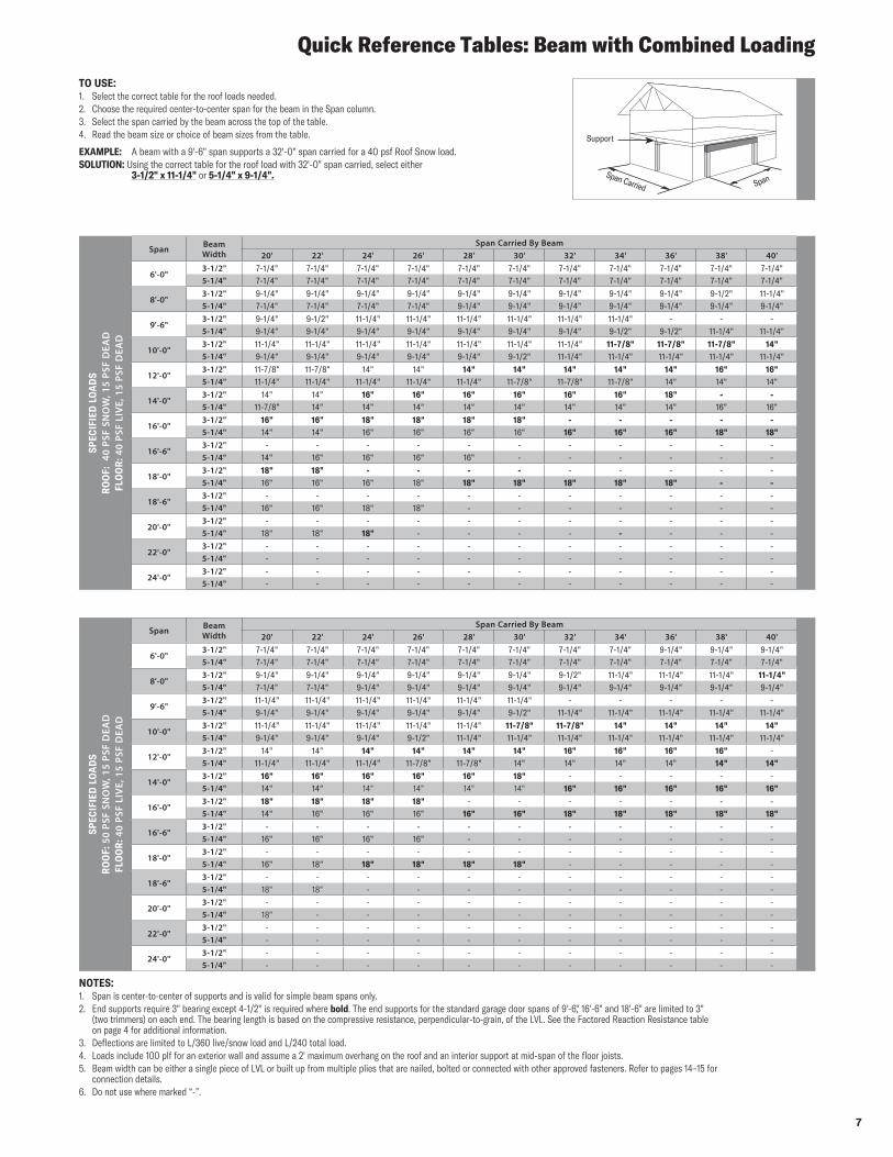
Quick Reference Tables: Beam with Combined Loading
TO USE:1. Select the correct table for the roof loads needed.2. Choose the required center-to-center span for the beam in the Span column.3. Select the span carried by the beam across the top of the table.4. Read the beam size or choice of beam sizes from the table.
EXAMPLE: A beam with a 9'-6" span supports a 32'-0" span carried for a 40 psf Roof Snow load.SOLUTION: Using the correct table for the roof load with 32'-0" span carried, select either
3-1/2" x 11-1/4" or 5-1/4" x 9-1/4".
SPEC
IFIE
D L
OA
DS
RO
OF:
40
PSF
SNO
W, 1
5 PS
F D
EAD
FLO
OR
: 40
PSF
LIV
E, 1
5 PS
F D
EAD
Span Beam Width
Span Carried By Beam20' 22' 24' 26' 28' 30' 32' 34' 36' 38' 40'
6'-0"3-1/2" 7-1/4" 7-1/4" 7-1/4" 7-1/4" 7-1/4" 7-1/4" 7-1/4" 7-1/4" 7-1/4" 7-1/4" 7-1/4"5-1/4" 7-1/4" 7-1/4" 7-1/4" 7-1/4" 7-1/4" 7-1/4" 7-1/4" 7-1/4" 7-1/4" 7-1/4" 7-1/4"
8'-0"3-1/2" 9-1/4" 9-1/4" 9-1/4" 9-1/4" 9-1/4" 9-1/4" 9-1/4" 9-1/4" 9-1/4" 9-1/2" 11-1/4"5-1/4" 7-1/4" 7-1/4" 7-1/4" 7-1/4" 9-1/4" 9-1/4" 9-1/4" 9-1/4" 9-1/4" 9-1/4" 9-1/4"
9'-6"3-1/2" 9-1/4" 9-1/2" 11-1/4" 11-1/4" 11-1/4" 11-1/4" 11-1/4" 11-1/4" - - -5-1/4" 9-1/4" 9-1/4" 9-1/4" 9-1/4" 9-1/4" 9-1/4" 9-1/4" 9-1/2" 9-1/2" 11-1/4" 11-1/4"
10'-0"3-1/2" 11-1/4" 11-1/4" 11-1/4" 11-1/4" 11-1/4" 11-1/4" 11-1/4" 11-7/8" 11-7/8" 11-7/8" 14"5-1/4" 9-1/4" 9-1/4" 9-1/4" 9-1/4" 9-1/4" 9-1/2" 11-1/4" 11-1/4" 11-1/4" 11-1/4" 11-1/4"
12'-0"3-1/2" 11-7/8" 11-7/8" 14" 14" 14" 14" 14" 14" 14" 16" 16"5-1/4" 11-1/4" 11-1/4" 11-1/4" 11-1/4" 11-1/4" 11-7/8" 11-7/8" 11-7/8" 14" 14" 14"
14'-0"3-1/2" 14" 14" 16" 16" 16" 16" 16" 16" 18" - -5-1/4" 11-7/8" 14" 14" 14" 14" 14" 14" 14" 14" 16" 16"
16'-0"3-1/2" 16" 16" 18" 18" 18" 18" - - - - -5-1/4" 14" 14" 16" 16" 16" 16" 16" 16" 16" 18" 18"
16'-6"3-1/2" - - - - - - - - - - -5-1/4" 14" 16" 16" 16" 16" - - - - - -
18'-0"3-1/2" 18" 18" - - - - - - - - -5-1/4" 16" 16" 16" 18" 18" 18" 18" 18" 18" - -
18'-6"3-1/2" - - - - - - - - - - -5-1/4" 16" 16" 18" 18" - - - - - - -
20'-0"3-1/2" - - - - - - - - - - -5-1/4" 18" 18" 18" - - - - - - - -
22'-0"3-1/2" - - - - - - - - - - -5-1/4" - - - - - - - - - - -
24'-0"3-1/2" - - - - - - - - - - -5-1/4" - - - - - - - - - - -
SPEC
IFIE
D L
OA
DS
RO
OF:
50
PSF
SNO
W, 1
5 PS
F D
EAD
FLO
OR
: 40
PSF
LIV
E, 1
5 PS
F D
EAD
Span Beam Width
Span Carried By Beam20' 22' 24' 26' 28' 30' 32' 34' 36' 38' 40'
6'-0"3-1/2" 7-1/4" 7-1/4" 7-1/4" 7-1/4" 7-1/4" 7-1/4" 7-1/4" 7-1/4" 9-1/4" 9-1/4" 9-1/4"5-1/4" 7-1/4" 7-1/4" 7-1/4" 7-1/4" 7-1/4" 7-1/4" 7-1/4" 7-1/4" 7-1/4" 7-1/4" 7-1/4"
8'-0"3-1/2" 9-1/4" 9-1/4" 9-1/4" 9-1/4" 9-1/4" 9-1/4" 9-1/2" 11-1/4" 11-1/4" 11-1/4" 11-1/4"5-1/4" 7-1/4" 7-1/4" 9-1/4" 9-1/4" 9-1/4" 9-1/4" 9-1/4" 9-1/4" 9-1/4" 9-1/4" 9-1/4"
9'-6"3-1/2" 11-1/4" 11-1/4" 11-1/4" 11-1/4" 11-1/4" 11-1/4" - - - - -5-1/4" 9-1/4" 9-1/4" 9-1/4" 9-1/4" 9-1/4" 9-1/2" 11-1/4" 11-1/4" 11-1/4" 11-1/4" 11-1/4"
10'-0"3-1/2" 11-1/4" 11-1/4" 11-1/4" 11-1/4" 11-1/4" 11-7/8" 11-7/8" 14" 14" 14" 14"5-1/4" 9-1/4" 9-1/4" 9-1/4" 9-1/2" 11-1/4" 11-1/4" 11-1/4" 11-1/4" 11-1/4" 11-1/4" 11-1/4"
12'-0"3-1/2" 14" 14" 14" 14" 14" 14" 16" 16" 16" 16" -5-1/4" 11-1/4" 11-1/4" 11-1/4" 11-7/8" 11-7/8" 14" 14" 14" 14" 14" 14"
14'-0"3-1/2" 16" 16" 16" 16" 16" 18" - - - - -5-1/4" 14" 14" 14" 14" 14" 14" 16" 16" 16" 16" 16"
16'-0"3-1/2" 18" 18" 18" 18" - - - - - - -5-1/4" 14" 16" 16" 16" 16" 16" 18" 18" 18" 18" 18"
16'-6"3-1/2" - - - - - - - - - - -5-1/4" 16" 16" 16" 16" - - - - - - -
18'-0"3-1/2" - - - - - - - - - - -5-1/4" 16" 18" 18" 18" 18" 18" - - - - -
18'-6"3-1/2" - - - - - - - - - - -5-1/4" 18" 18" - - - - - - - - -
20'-0"3-1/2" - - - - - - - - - - -5-1/4" 18" - - - - - - - - - -
22'-0"3-1/2" - - - - - - - - - - -5-1/4" - - - - - - - - - - -
24'-0"3-1/2" - - - - - - - - - - -5-1/4" - - - - - - - - - - -
NOTES:1. Span is center-to-center of supports and is valid for simple beam spans only.2. End supports require 3" bearing except 4-1/2" is required where bold. The end supports for the standard garage door spans of 9'-6," 16'-6" and 18'-6" are limited to 3"
(two trimmers) on each end. The bearing length is based on the compressive resistance, perpendicular-to-grain, of the LVL. See the Factored Reaction Resistance table on page 4 for additional information.
3. Deflections are limited to L/360 live/snow load and L/240 total load.4. Loads include 100 plf for an exterior wall and assume a 2' maximum overhang on the roof and an interior support at mid-span of the floor joists.5. Beam width can be either a single piece of LVL or built up from multiple plies that are nailed, bolted or connected with other approved fasteners. Refer to pages 14–15 for
connection details.6. Do not use where marked “-”.
Span Carried Span
Support
8
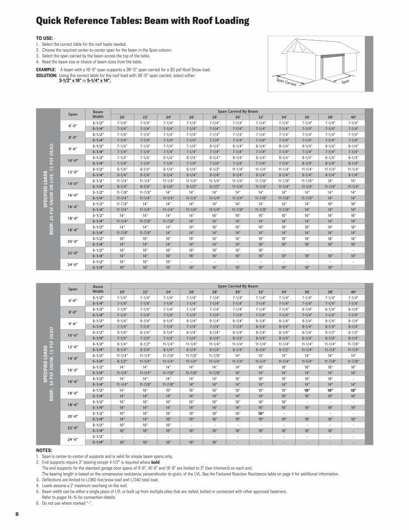
Quick Reference Tables: Beam with Roof Loading
Span Carried Span
TO USE:1. Select the correct table for the roof loads needed.2. Choose the required center-to-center span for the beam in the Span column.3. Select the span carried by the beam across the top of the table.4. Read the beam size or choice of beam sizes from the table.
EXAMPLE: A beam with a 16'-6" span supports a 36'-0" span carried for a 30 psf Roof Snow load.SOLUTION: Using the correct table for the roof load with 36'-0" span carried, select either
3-1/2" x 16" or 5-1/4" x 14".
SPEC
IFIE
D L
OA
DS
RO
OF:
20
PSF
SNO
W O
R LI
VE,
15
PSF
DEA
D
Span Beam Width
Span Carried By Beam20' 22' 24' 26' 28' 30' 32' 34' 36' 38' 40'
6'-0"3-1/2" 7-1/4" 7-1/4" 7-1/4" 7-1/4" 7-1/4" 7-1/4" 7-1/4" 7-1/4" 7-1/4" 7-1/4" 7-1/4"5-1/4" 7-1/4" 7-1/4" 7-1/4" 7-1/4" 7-1/4" 7-1/4" 7-1/4" 7-1/4" 7-1/4" 7-1/4" 7-1/4"
8'-0"3-1/2" 7-1/4" 7-1/4" 7-1/4" 7-1/4" 7-1/4" 7-1/4" 7-1/4" 7-1/4" 7-1/4" 7-1/4" 7-1/4"5-1/4" 7-1/4" 7-1/4" 7-1/4" 7-1/4" 7-1/4" 7-1/4" 7-1/4" 7-1/4" 7-1/4" 7-1/4" 7-1/4"
9'-6"3-1/2" 7-1/4" 7-1/4" 7-1/4" 7-1/4" 9-1/4" 9-1/4" 9-1/4" 9-1/4" 9-1/4" 9-1/4" 9-1/4"5-1/4" 7-1/4" 7-1/4" 7-1/4" 7-1/4" 7-1/4" 7-1/4" 7-1/4" 7-1/4" 7-1/4" 7-1/4" 7-1/4"
10'-0"3-1/2" 7-1/4" 7-1/4" 9-1/4" 9-1/4" 9-1/4" 9-1/4" 9-1/4" 9-1/4" 9-1/4" 9-1/4" 9-1/4"5-1/4" 7-1/4" 7-1/4" 7-1/4" 7-1/4" 7-1/4" 7-1/4" 7-1/4" 7-1/4" 9-1/4" 9-1/4" 9-1/4"
12'-0"3-1/2" 9-1/4" 9-1/4" 9-1/4" 9-1/4" 9-1/2" 11-1/4" 11-1/4" 11-1/4" 11-1/4" 11-1/4" 11-1/4"5-1/4" 9-1/4" 9-1/4" 9-1/4" 9-1/4" 9-1/4" 9-1/4" 9-1/4" 9-1/4" 9-1/4" 9-1/4" 9-1/4"
14'-0"3-1/2" 11-1/4" 11-1/4" 11-1/4" 11-1/4" 11-1/4" 11-1/4" 11-7/8" 11-7/8" 11-7/8" 14" 14"5-1/4" 9-1/4" 9-1/4" 9-1/4" 9-1/2" 9-1/2" 11-1/4" 11-1/4" 11-1/4" 11-1/4" 11-1/4" 11-1/4"
16'-0"3-1/2" 11-7/8" 11-7/8" 14" 14" 14" 14" 14" 14" 14" 14" 14"5-1/4" 11-1/4" 11-1/4" 11-1/4" 11-1/4" 11-1/4" 11-1/4" 11-7/8" 11-7/8" 11-7/8" 14" 14"
16'-6"3-1/2" 11-7/8" 14" 14" 14" 14" 14" 14" 14" 14" 16" 16"5-1/4" 11-1/4" 11-1/4" 11-1/4" 11-1/4" 11-1/4" 11-7/8" 11-7/8" 11-7/8" 14" 14" 14"
18'-0"3-1/2" 14" 14" 14" 14" 16" 16" 16" 16" 16" 16" 16"5-1/4" 11-1/4" 11-7/8" 11-7/8" 14" 14" 14" 14" 14" 14" 14" 14"
18'-6"3-1/2" 14" 14" 14" 16" 16" 16" 16" 16" 16" 16" 18"5-1/4" 11-7/8" 11-7/8" 14" 14" 14" 14" 14" 14" 14" 14" 14"
20'-0"3-1/2" 16" 16" 16" 16" 16" 16" 18" 18" 18" 18" 18"5-1/4" 14" 14" 14" 14" 14" 14" 16" 16" 16" 16" 16"
22'-0"3-1/2" 16" 16" 18" 18" 18" 18" 18" - - - -5-1/4" 14" 14" 16" 16" 16" 16" 16" 16" 18" 18" 18"
24'-0"3-1/2" 18" 18" 18" - - - - - - - -5-1/4" 16" 16" 16" 16" 18" 18" 18" 18" 18" 18" -
SPEC
IFIE
D L
OA
DS
RO
OF:
30
PSF
SNO
W, 1
5 PS
F D
EAD
Span Beam Width
Span Carried By Beam20' 22' 24' 26' 28' 30' 32' 34' 36' 38' 40'
6'-0"3-1/2" 7-1/4" 7-1/4" 7-1/4" 7-1/4" 7-1/4" 7-1/4" 7-1/4" 7-1/4" 7-1/4" 7-1/4" 7-1/4"5-1/4" 7-1/4" 7-1/4" 7-1/4" 7-1/4" 7-1/4" 7-1/4" 7-1/4" 7-1/4" 7-1/4" 7-1/4" 7-1/4"
8'-0"3-1/2" 7-1/4" 7-1/4" 7-1/4" 7-1/4" 7-1/4" 7-1/4" 7-1/4" 7-1/4" 9-1/4" 9-1/4" 9-1/4"5-1/4" 7-1/4" 7-1/4" 7-1/4" 7-1/4" 7-1/4" 7-1/4" 7-1/4" 7-1/4" 7-1/4" 7-1/4" 7-1/4"
9'-6"3-1/2" 9-1/4" 9-1/4" 9-1/4" 9-1/4" 9-1/4" 9-1/4" 9-1/4" 9-1/4" 9-1/4" 9-1/4" 9-1/4"5-1/4" 7-1/4" 7-1/4" 7-1/4" 7-1/4" 7-1/4" 7-1/4" 9-1/4" 9-1/4" 9-1/4" 9-1/4" 9-1/4"
10'-0"3-1/2" 9-1/4" 9-1/4" 9-1/4" 9-1/4" 9-1/4" 9-1/4" 9-1/4" 9-1/4" 9-1/4" 9-1/2" 9-1/2"5-1/4" 7-1/4" 7-1/4" 7-1/4" 7-1/4" 9-1/4" 9-1/4" 9-1/4" 9-1/4" 9-1/4" 9-1/4" 9-1/4"
12'-0"3-1/2" 9-1/4" 9-1/2" 11-1/4" 11-1/4" 11-1/4" 11-1/4" 11-1/4" 11-1/4" 11-1/4" 11-1/4" 11-7/8"5-1/4" 9-1/4" 9-1/4" 9-1/4" 9-1/4" 9-1/4" 9-1/4" 9-1/4" 9-1/2" 11-1/4" 11-1/4" 11-1/4"
14'-0"3-1/2" 11-1/4" 11-1/4" 11-7/8" 11-7/8" 11-7/8" 14" 14" 14" 14" 14" 14"5-1/4" 9-1/2" 11-1/4" 11-1/4" 11-1/4" 11-1/4" 11-1/4" 11-1/4" 11-1/4" 11-1/4" 11-7/8" 11-7/8"
16'-0"3-1/2" 14" 14" 14" 14" 14" 14" 16" 16" 16" 16" 16"5-1/4" 11-1/4" 11-1/4" 11-7/8" 11-7/8" 11-7/8" 14" 14" 14" 14" 14" 14"
16'-6"3-1/2" 14" 14" 14" 14" 14" 16" 16" 16" 16" 16" -5-1/4" 11-1/4" 11-7/8" 11-7/8" 14" 14" 14" 14" 14" 14" 14" 14"
18'-0"3-1/2" 14" 16" 16" 16" 16" 16" 16" 18" 18" 18" 18"5-1/4" 14" 14" 14" 14" 14" 14" 14" 16" 16" 16" 16"
18'-6"3-1/2" 16" 16" 16" 16" 16" 18" 18" 18" - - -5-1/4" 14" 14" 14" 14" 14" 14" 16" 16" 16" 16" 16"
20'-0"3-1/2" 16" 16" 18" 18" 18" 18" 18" - - - -5-1/4" 14" 14" 16" 16" 16" 16" 16" 16" 16" 18" 18"
22'-0"3-1/2" 18" 18" 18" - - - - - - - -5-1/4" 16" 16" 16" 16" 18" 18" 18" 18" 18" 18" -
24'-0"3-1/2" - - - - - - - - - - -5-1/4" 18" 18" 18" 18" 18" - - - - - -
NOTES:1. Span is center-to-center of supports and is valid for simple beam spans only.2. End supports require 3" bearing except 4-1/2" is required where bold. The end supports for the standard garage door spans of 9'-6", 16'-6" and 18'-6" are limited to 3" (two trimmers) on each end. The bearing length is based on the compressive resistance, perpendicular-to-grain, of the LVL. See the Factored Reaction Resistance table on page 4 for additional information.3. Deflections are limited to L/360 live/snow load and L/240 total load.4. Loads assume a 2' maximum overhang on the roof.5. Beam width can be either a single piece of LVL or built up from multiple plies that are nailed, bolted or connected with other approved fasteners. Refer to pages 14–15 for connection details.6. Do not use where marked “-”.
9
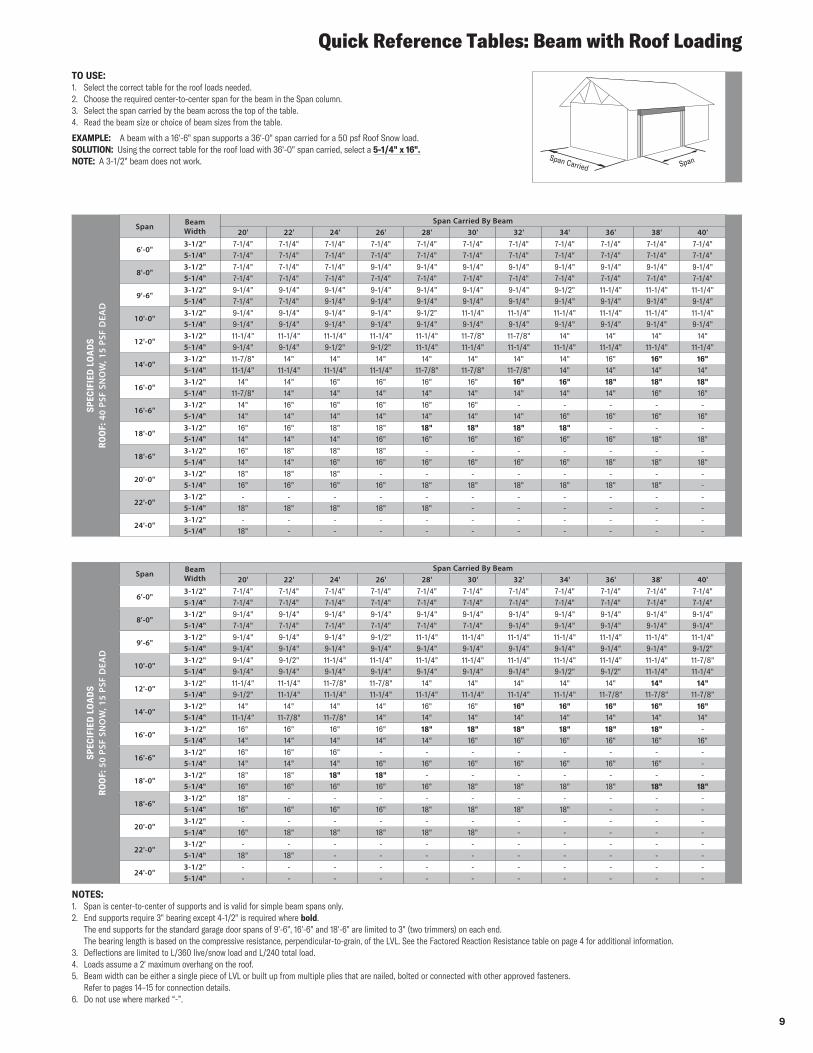
Quick Reference Tables: Beam with Roof Loading
SPEC
IFIE
D L
OA
DS
RO
OF:
40
PSF
SNO
W, 1
5 PS
F D
EAD
Span Beam Width
Span Carried By Beam20' 22' 24' 26' 28' 30' 32' 34' 36' 38' 40'
6'-0"3-1/2" 7-1/4" 7-1/4" 7-1/4" 7-1/4" 7-1/4" 7-1/4" 7-1/4" 7-1/4" 7-1/4" 7-1/4" 7-1/4"5-1/4" 7-1/4" 7-1/4" 7-1/4" 7-1/4" 7-1/4" 7-1/4" 7-1/4" 7-1/4" 7-1/4" 7-1/4" 7-1/4"
8'-0"3-1/2" 7-1/4" 7-1/4" 7-1/4" 9-1/4" 9-1/4" 9-1/4" 9-1/4" 9-1/4" 9-1/4" 9-1/4" 9-1/4"5-1/4" 7-1/4" 7-1/4" 7-1/4" 7-1/4" 7-1/4" 7-1/4" 7-1/4" 7-1/4" 7-1/4" 7-1/4" 7-1/4"
9'-6"3-1/2" 9-1/4" 9-1/4" 9-1/4" 9-1/4" 9-1/4" 9-1/4" 9-1/4" 9-1/2" 11-1/4" 11-1/4" 11-1/4"5-1/4" 7-1/4" 7-1/4" 9-1/4" 9-1/4" 9-1/4" 9-1/4" 9-1/4" 9-1/4" 9-1/4" 9-1/4" 9-1/4"
10'-0"3-1/2" 9-1/4" 9-1/4" 9-1/4" 9-1/4" 9-1/2" 11-1/4" 11-1/4" 11-1/4" 11-1/4" 11-1/4" 11-1/4"5-1/4" 9-1/4" 9-1/4" 9-1/4" 9-1/4" 9-1/4" 9-1/4" 9-1/4" 9-1/4" 9-1/4" 9-1/4" 9-1/4"
12'-0"3-1/2" 11-1/4" 11-1/4" 11-1/4" 11-1/4" 11-1/4" 11-7/8" 11-7/8" 14" 14" 14" 14"5-1/4" 9-1/4" 9-1/4" 9-1/2" 9-1/2" 11-1/4" 11-1/4" 11-1/4" 11-1/4" 11-1/4" 11-1/4" 11-1/4"
14'-0"3-1/2" 11-7/8" 14" 14" 14" 14" 14" 14" 14" 16" 16" 16"5-1/4" 11-1/4" 11-1/4" 11-1/4" 11-1/4" 11-7/8" 11-7/8" 11-7/8" 14" 14" 14" 14"
16'-0"3-1/2" 14" 14" 16" 16" 16" 16" 16" 16" 18" 18" 18"5-1/4" 11-7/8" 14" 14" 14" 14" 14" 14" 14" 14" 16" 16"
16'-6"3-1/2" 14" 16" 16" 16" 16" 16" - - - - -5-1/4" 14" 14" 14" 14" 14" 14" 14" 16" 16" 16" 16"
18'-0"3-1/2" 16" 16" 18" 18" 18" 18" 18" 18" - - -5-1/4" 14" 14" 14" 16" 16" 16" 16" 16" 16" 18" 18"
18'-6"3-1/2" 16" 18" 18" 18" - - - - - - -5-1/4" 14" 14" 16" 16" 16" 16" 16" 16" 18" 18" 18"
20'-0"3-1/2" 18" 18" 18" - - - - - - - -5-1/4" 16" 16" 16" 16" 18" 18" 18" 18" 18" 18" -
22'-0"3-1/2" - - - - - - - - - - -5-1/4" 18" 18" 18" 18" 18" - - - - - -
24'-0"3-1/2" - - - - - - - - - - -5-1/4" 18" - - - - - - - - - -
SPEC
IFIE
D L
OA
DS
RO
OF:
50
PSF
SNO
W, 1
5 PS
F D
EAD
Span Beam Width
Span Carried By Beam20' 22' 24' 26' 28' 30' 32' 34' 36' 38' 40'
6'-0"3-1/2" 7-1/4" 7-1/4" 7-1/4" 7-1/4" 7-1/4" 7-1/4" 7-1/4" 7-1/4" 7-1/4" 7-1/4" 7-1/4"5-1/4" 7-1/4" 7-1/4" 7-1/4" 7-1/4" 7-1/4" 7-1/4" 7-1/4" 7-1/4" 7-1/4" 7-1/4" 7-1/4"
8'-0"3-1/2" 9-1/4" 9-1/4" 9-1/4" 9-1/4" 9-1/4" 9-1/4" 9-1/4" 9-1/4" 9-1/4" 9-1/4" 9-1/4"5-1/4" 7-1/4" 7-1/4" 7-1/4" 7-1/4" 7-1/4" 7-1/4" 9-1/4" 9-1/4" 9-1/4" 9-1/4" 9-1/4"
9'-6"3-1/2" 9-1/4" 9-1/4" 9-1/4" 9-1/2" 11-1/4" 11-1/4" 11-1/4" 11-1/4" 11-1/4" 11-1/4" 11-1/4"5-1/4" 9-1/4" 9-1/4" 9-1/4" 9-1/4" 9-1/4" 9-1/4" 9-1/4" 9-1/4" 9-1/4" 9-1/4" 9-1/2"
10'-0"3-1/2" 9-1/4" 9-1/2" 11-1/4" 11-1/4" 11-1/4" 11-1/4" 11-1/4" 11-1/4" 11-1/4" 11-1/4" 11-7/8"5-1/4" 9-1/4" 9-1/4" 9-1/4" 9-1/4" 9-1/4" 9-1/4" 9-1/4" 9-1/2" 9-1/2" 11-1/4" 11-1/4"
12'-0"3-1/2" 11-1/4" 11-1/4" 11-7/8" 11-7/8" 14" 14" 14" 14" 14" 14" 14"5-1/4" 9-1/2" 11-1/4" 11-1/4" 11-1/4" 11-1/4" 11-1/4" 11-1/4" 11-1/4" 11-7/8" 11-7/8" 11-7/8"
14'-0"3-1/2" 14" 14" 14" 14" 16" 16" 16" 16" 16" 16" 16"5-1/4" 11-1/4" 11-7/8" 11-7/8" 14" 14" 14" 14" 14" 14" 14" 14"
16'-0"3-1/2" 16" 16" 16" 16" 18" 18" 18" 18" 18" 18" -5-1/4" 14" 14" 14" 14" 14" 16" 16" 16" 16" 16" 16"
16'-6"3-1/2" 16" 16" 16" - - - - - - - -5-1/4" 14" 14" 14" 16" 16" 16" 16" 16" 16" 16" -
18'-0"3-1/2" 18" 18" 18" 18" - - - - - - -5-1/4" 16" 16" 16" 16" 16" 18" 18" 18" 18" 18" 18"
18'-6"3-1/2" 18" - - - - - - - - - -5-1/4" 16" 16" 16" 16" 18" 18" 18" 18" - - -
20'-0"3-1/2" - - - - - - - - - - -5-1/4" 16" 18" 18" 18" 18" 18" - - - - -
22'-0"3-1/2" - - - - - - - - - - -5-1/4" 18" 18" - - - - - - - - -
24'-0"3-1/2" - - - - - - - - - - -5-1/4" - - - - - - - - - - -
TO USE:1. Select the correct table for the roof loads needed.2. Choose the required center-to-center span for the beam in the Span column.3. Select the span carried by the beam across the top of the table.4. Read the beam size or choice of beam sizes from the table.
EXAMPLE: A beam with a 16'-6" span supports a 36'-0" span carried for a 50 psf Roof Snow load.SOLUTION: Using the correct table for the roof load with 36'-0" span carried, select a 5-1/4" x 16". NOTE: A 3-1/2" beam does not work.
NOTES:1. Span is center-to-center of supports and is valid for simple beam spans only.2. End supports require 3" bearing except 4-1/2" is required where bold. The end supports for the standard garage door spans of 9'-6", 16'-6" and 18'-6" are limited to 3" (two trimmers) on each end. The bearing length is based on the compressive resistance, perpendicular-to-grain, of the LVL. See the Factored Reaction Resistance table on page 4 for additional information.3. Deflections are limited to L/360 live/snow load and L/240 total load.4. Loads assume a 2' maximum overhang on the roof.5. Beam width can be either a single piece of LVL or built up from multiple plies that are nailed, bolted or connected with other approved fasteners. Refer to pages 14–15 for connection details.6. Do not use where marked “-”.
Span Carried Span
10
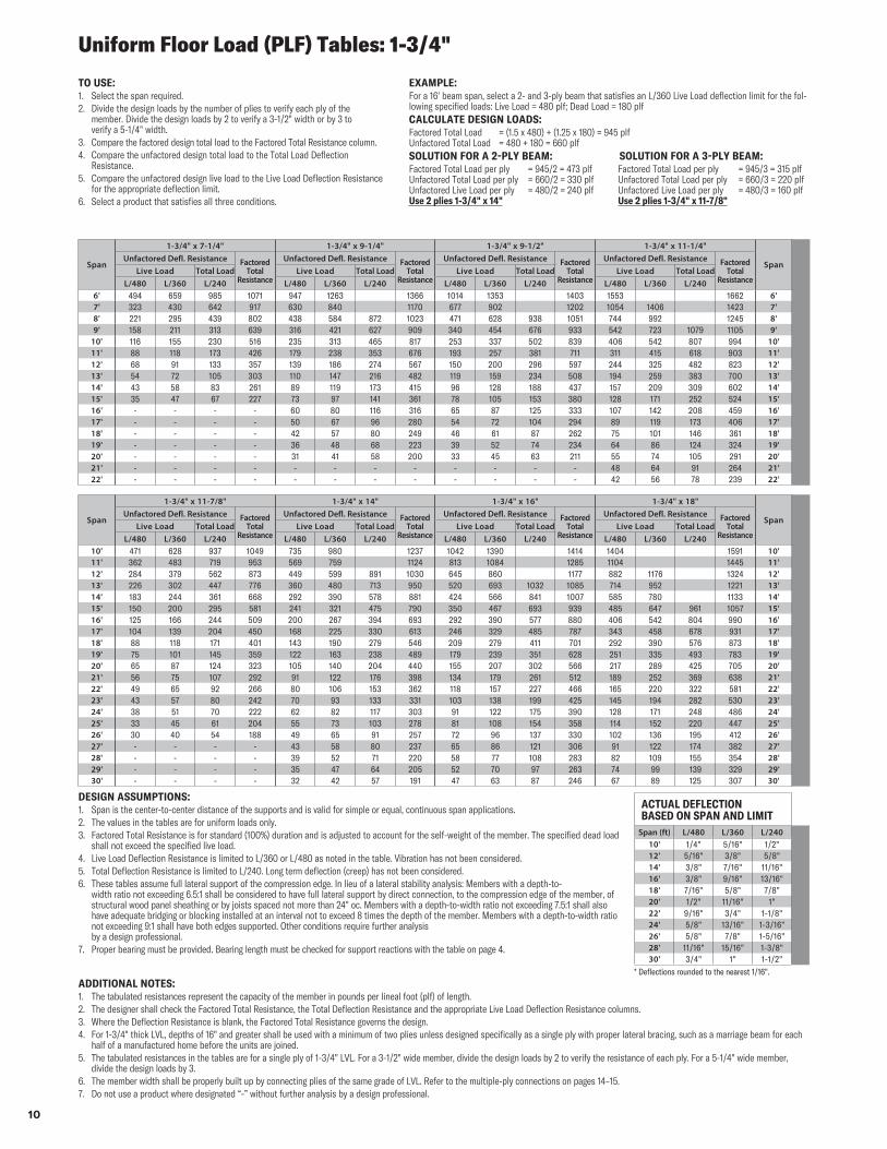
TO USE:1. Select the span required.2. Divide the design loads by the number of plies to verify each ply of the
member. Divide the design loads by 2 to verify a 3-1/2" width or by 3 to verify a 5-1/4" width.
3. Compare the factored design total load to the Factored Total Resistance column.4. Compare the unfactored design total load to the Total Load Deflection
Resistance.5. Compare the unfactored design live load to the Live Load Deflection Resistance
for the appropriate deflection limit.6. Select a product that satisfies all three conditions.
DESIGN ASSUMPTIONS:1. Span is the center-to-center distance of the supports and is valid for simple or equal, continuous span applications.2. The values in the tables are for uniform loads only.3. Factored Total Resistance is for standard (100%) duration and is adjusted to account for the self-weight of the member. The specified dead load
shall not exceed the specified live load.4. Live Load Deflection Resistance is limited to L/360 or L/480 as noted in the table. Vibration has not been considered.5. Total Deflection Resistance is limited to L/240. Long term deflection (creep) has not been considered.6. These tables assume full lateral support of the compression edge. In lieu of a lateral stability analysis: Members with a depth-to-
width ratio not exceeding 6.5:1 shall be considered to have full lateral support by direct connection, to the compression edge of the member, of structural wood panel sheathing or by joists spaced not more than 24" oc. Members with a depth-to-width ratio not exceeding 7.5:1 shall also have adequate bridging or blocking installed at an interval not to exceed 8 times the depth of the member. Members with a depth-to-width ratio not exceeding 9:1 shall have both edges supported. Other conditions require further analysis by a design professional.
7. Proper bearing must be provided. Bearing length must be checked for support reactions with the table on page 4.
Span
1-3/4" x 7-1/4" 1-3/4" x 9-1/4" 1-3/4" x 9-1/2" 1-3/4" x 11-1/4"
SpanUnfactored Defl. Resistance Factored
Total Resistance
Unfactored Defl. Resistance Factored Total
Resistance
Unfactored Defl. Resistance Factored Total
Resistance
Unfactored Defl. Resistance Factored Total
ResistanceLive Load Total Load Live Load Total Load Live Load Total Load Live Load Total Load
L/480 L/360 L/240 L/480 L/360 L/240 L/480 L/360 L/240 L/480 L/360 L/2406' 494 659 985 1071 947 1263 1366 1014 1353 1403 1553 1662 6'7' 323 430 642 917 630 840 1170 677 902 1202 1054 1406 1423 7'8' 221 295 439 802 438 584 872 1023 471 628 938 1051 744 992 1245 8'9' 158 211 313 639 316 421 627 909 340 454 676 933 542 723 1079 1105 9'
10' 116 155 230 516 235 313 465 817 253 337 502 839 406 542 807 994 10'11' 88 118 173 426 179 238 353 676 193 257 381 711 311 415 618 903 11'12' 68 91 133 357 139 186 274 567 150 200 296 597 244 325 482 823 12'13' 54 72 105 303 110 147 216 482 119 159 234 508 194 259 383 700 13'14' 43 58 83 261 89 119 173 415 96 128 188 437 157 209 309 602 14'15' 35 47 67 227 73 97 141 361 78 105 153 380 128 171 252 524 15'16' - - - - 60 80 116 316 65 87 125 333 107 142 208 459 16'17' - - - - 50 67 96 280 54 72 104 294 89 119 173 406 17'18' - - - - 42 57 80 249 46 61 87 262 75 101 146 361 18'19' - - - - 36 48 68 223 39 52 74 234 64 86 124 324 19'20' - - - - 31 41 58 200 33 45 63 211 55 74 105 291 20'21' - - - - - - - - - - - - 48 64 91 264 21'22' - - - - - - - - - - - - 42 56 78 239 22'
ACTUAL DEFLECTION BASED ON SPAN AND LIMIT
Span (ft) L/480 L/360 L/24010' 1/4" 5/16" 1/2"12' 5/16" 3/8" 5/8"14' 3/8" 7/16" 11/16"16' 3/8" 9/16" 13/16"18' 7/16" 5/8" 7/8"20' 1/2" 11/16" 1"22' 9/16" 3/4" 1-1/8"24' 5/8" 13/16" 1-3/16"26' 5/8" 7/8" 1-5/16"28' 11/16" 15/16" 1-3/8"30' 3/4" 1" 1-1/2"
EXAMPLE:For a 16' beam span, select a 2- and 3-ply beam that satisfies an L/360 Live Load deflection limit for the fol-lowing specified loads: Live Load = 480 plf; Dead Load = 180 plfCALCULATE DESIGN LOADS:Factored Total Load = (1.5 x 480) + (1.25 x 180) = 945 plf Unfactored Total Load = 480 + 180 = 660 plfSOLUTION FOR A 2-PLY BEAM: SOLUTION FOR A 3-PLY BEAM:Factored Total Load per ply = 945/2 = 473 plf Factored Total Load per ply = 945/3 = 315 plf Unfactored Total Load per ply = 660/2 = 330 plf Unfactored Total Load per ply = 660/3 = 220 plf Unfactored Live Load per ply = 480/2 = 240 plf Unfactored Live Load per ply = 480/3 = 160 plf Use 2 plies 1-3/4" x 14" Use 2 plies 1-3/4" x 11-7/8"
Span
1-3/4" x 11-7/8" 1-3/4" x 14" 1-3/4" x 16" 1-3/4" x 18"
SpanUnfactored Defl. Resistance Factored
Total Resistance
Unfactored Defl. Resistance Factored Total
Resistance
Unfactored Defl. Resistance Factored Total
Resistance
Unfactored Defl. Resistance Factored Total
ResistanceLive Load Total Load Live Load Total Load Live Load Total Load Live Load Total Load
L/480 L/360 L/240 L/480 L/360 L/240 L/480 L/360 L/240 L/480 L/360 L/24010' 471 628 937 1049 735 980 1237 1042 1390 1414 1404 1591 10'11' 362 483 719 953 569 759 1124 813 1084 1285 1104 1445 11'12' 284 379 562 873 449 599 891 1030 645 860 1177 882 1176 1324 12'13' 226 302 447 776 360 480 713 950 520 693 1032 1085 714 952 1221 13'14' 183 244 361 668 292 390 578 881 424 566 841 1007 585 780 1133 14'15' 150 200 295 581 241 321 475 790 350 467 693 939 485 647 961 1057 15'16' 125 166 244 509 200 267 394 693 292 390 577 880 406 542 804 990 16'17' 104 139 204 450 168 225 330 613 246 329 485 787 343 458 678 931 17'18' 88 118 171 401 143 190 279 546 209 279 411 701 292 390 576 873 18'19' 75 101 145 359 122 163 238 489 179 239 351 628 251 335 493 783 19'20' 65 87 124 323 105 140 204 440 155 207 302 566 217 289 425 705 20'21' 56 75 107 292 91 122 176 398 134 179 261 512 189 252 369 638 21'22' 49 65 92 266 80 106 153 362 118 157 227 466 165 220 322 581 22'23' 43 57 80 242 70 93 133 331 103 138 199 425 145 194 282 530 23'24' 38 51 70 222 62 82 117 303 91 122 175 390 128 171 248 486 24'25' 33 45 61 204 55 73 103 278 81 108 154 358 114 152 220 447 25'26' 30 40 54 188 49 65 91 257 72 96 137 330 102 136 195 412 26'27' - - - - 43 58 80 237 65 86 121 306 91 122 174 382 27'28' - - - - 39 52 71 220 58 77 108 283 82 109 155 354 28'29' - - - - 35 47 64 205 52 70 97 263 74 99 139 329 29'30' - - - - 32 42 57 191 47 63 87 246 67 89 125 307 30'
Uniform Floor Load (PLF) Tables: 1-3/4"
ADDITIONAL NOTES:1. The tabulated resistances represent the capacity of the member in pounds per lineal foot (plf) of length.2. The designer shall check the Factored Total Resistance, the Total Deflection Resistance and the appropriate Live Load Deflection Resistance columns.3. Where the Deflection Resistance is blank, the Factored Total Resistance governs the design.4. For 1-3/4" thick LVL, depths of 16" and greater shall be used with a minimum of two plies unless designed specifically as a single ply with proper lateral bracing, such as a marriage beam for each
half of a manufactured home before the units are joined.5. The tabulated resistances in the tables are for a single ply of 1-3/4" LVL. For a 3-1/2" wide member, divide the design loads by 2 to verify the resistance of each ply. For a 5-1/4" wide member,
divide the design loads by 3.6. The member width shall be properly built up by connecting plies of the same grade of LVL. Refer to the multiple-ply connections on pages 14–15.7. Do not use a product where designated “-” without further analysis by a design professional.
* Deflections rounded to the nearest 1/16".
11
Span
1-3/4" x 7-1/4" 1-3/4" x 9-1/4" 1-3/4" x 9-1/2" 1-3/4" x 11-1/4"
SpanUnfactored Defl. Resistance Factored
Total Resistance
Unfactored Defl. Resistance Factored Total
Resistance
Unfactored Defl. Resistance Factored Total
Resistance
Unfactored Defl. Resistance Factored Total
ResistanceSnow/Live Load Total Load Snow/Live Load Total Load Snow/Live Load Total Load Snow/Live Load Total LoadL/360 L/240 L/180 L/360 L/240 L/180 L/360 L/240 L/180 L/360 L/240 L/180
6' 659 989 1071 1263 1366 1353 1403 1662 6'7' 430 646 857 917 840 1170 902 1202 1406 1423 7'8' 295 443 587 802 584 876 1023 628 943 1051 992 1245 8'9' 211 316 418 639 421 632 838 909 454 681 903 933 723 1085 1105 9'
10' 155 233 308 516 313 470 622 817 337 506 671 839 542 813 994 10'11' 118 177 232 426 238 358 473 676 257 386 510 711 415 623 826 903 11'12' 91 137 179 357 186 279 367 567 200 301 397 597 325 488 645 823 12'13' 72 108 141 303 147 221 290 482 159 239 314 508 259 388 513 700 13'14' 58 87 113 261 119 178 233 415 128 193 252 437 209 314 413 602 14'15' 47 71 91 227 97 146 190 361 105 157 205 380 171 257 338 524 15'16' 39 59 75 199 80 120 156 316 87 130 169 333 142 214 279 459 16'17' 32 49 62 175 67 101 130 280 72 109 141 294 119 179 233 406 17'18' - - - - 57 85 109 249 61 92 118 262 101 151 196 361 18'19' - - - - 48 72 92 223 52 78 100 234 86 129 167 324 19'20' - - - - 41 62 78 200 45 67 85 211 74 111 143 291 20'21' - - - - 36 54 67 181 39 58 73 191 64 96 123 264 21'22' - - - - 31 47 58 164 34 51 63 173 56 84 106 239 22'
Span
1-3/4" x 11-7/8" 1-3/4" x 14" 1-3/4" x 16" 1-3/4" x 18"
SpanUnfactored Defl. Resistance Factored
Total Resistance
Unfactored Defl. Resistance Factored Total
Resistance
Unfactored Defl. Resistance Factored Total
Resistance
Unfactored Defl. Resistance Factored Total
ResistanceSnow/Live Load Total Load Snow/Live Load Total Load Snow/Live Load Total Load Snow/Live Load Total LoadL/360 L/240 L/180 L/360 L/240 L/180 L/360 L/240 L/180 L/360 L/240 L/180
10' 628 943 1049 980 1237 1390 1414 1591 10'11' 483 725 953 759 1124 1084 1285 1445 11'12' 379 568 752 873 599 898 1030 860 1177 1176 1324 12'13' 302 453 598 776 480 720 950 693 1040 1085 952 1221 13'14' 244 367 483 668 390 585 773 881 566 849 1007 780 1133 14'15' 200 301 395 581 321 482 635 790 467 701 927 939 647 970 1057 15'16' 166 250 327 509 267 401 528 693 390 585 772 880 542 813 990 16'17' 139 209 274 450 225 337 443 613 329 493 650 787 458 687 907 931 17'18' 118 177 231 401 190 286 374 546 279 419 551 701 390 585 771 873 18'19' 101 151 196 359 163 245 319 489 239 359 471 628 335 502 661 783 19'20' 87 130 168 323 140 211 274 440 207 310 406 566 289 434 570 705 20'21' 75 113 145 292 122 183 237 398 179 269 351 512 252 378 495 638 21'22' 65 98 125 266 106 160 206 362 157 236 306 466 220 331 432 581 22'23' 57 86 109 242 93 140 180 331 138 207 268 425 194 291 379 530 23'24' 51 76 96 222 82 124 158 303 122 183 236 390 171 257 334 486 24'25' 45 67 84 204 73 110 139 278 108 162 209 358 152 229 296 447 25'26' 40 60 74 188 65 98 123 257 96 145 185 330 136 204 263 412 26'27' 36 54 66 174 58 87 110 237 86 130 165 306 122 183 235 382 27'28' 32 48 58 161 52 78 98 220 77 116 147 283 109 164 210 354 28'29' - - - - 47 71 87 205 70 105 132 263 99 148 189 329 29'30' - - - - 42 64 78 191 63 95 119 246 89 134 170 307 30'
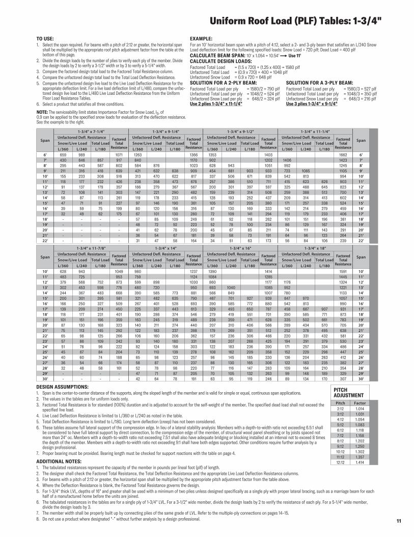
TO USE:1. Select the span required. For beams with a pitch of 2:12 or greater, the horizontal span
shall be multiplied by the appropriate roof pitch adjustment factor from the table at the bottom of this page.
2. Divide the design loads by the number of plies to verify each ply of the member. Divide the design loads by 2 to verify a 3-1/2" width or by 3 to verify a 5-1/4" width.
3. Compare the factored design total load to the Factored Total Resistance column.4. Compare the unfactored design total load to the Total Load Deflection Resistance.5. Compare the unfactored design live load to the Live Load Deflection Resistance for the
appropriate deflection limit. For a live load deflection limit of L/480, compare the unfac-tored design live load to the L/480 Live Load Deflection Resistance from the Uniform Floor Load Resistance Tables.
6. Select a product that satisfies all three conditions.
NOTE: The serviceability limit states Importance Factor for Snow Load, IS, of 0.9 can be applied to the specified snow loads for evaluation of the deflection resistance. See the example to the right.
EXAMPLE:For an 10' horizontal beam span with a pitch of 4:12, select a 2- and 3-ply beam that satisfies an L/240 Snow Load deflection limit for the following specified loads: Snow Load = 720 plf; Dead Load = 400 plfCALCULATE BEAM SPAN: 10' x 1.054 = 10.54' ∞ Use 11'CALCULATE DESIGN LOADS:Factored Total Load = (1.5 x 720) + (1.25 x 400) = 1580 plf Unfactored Total Load = (0.9 x 720) + 400 = 1048 plf Unfactored Snow Load = 0.9 x 720 = 648 plfSOLUTION FOR A 2-PLY BEAM: SOLUTION FOR A 3-PLY BEAM:Factored Total Load per ply = 1580/2 = 790 plf Factored Total Load per ply = 1580/3 = 527 plf Unfactored Total Load per ply = 1048/2 = 524 plf Unfactored Total Load per ply = 1048/3 = 350 plf Unfactored Snow Load per ply = 648/2 = 324 plf Unfactored Snow Load per ply = 648/3 = 216 plf Use 2 plies 1-3/4" x 11-1/4" Use 3 plies 1-3/4" x 9-1/4"
Uniform Roof Load (PLF) Tables: 1-3/4"
DESIGN ASSUMPTIONS:1. Span is the center-to-center distance of the supports, along the sloped length of the member and is valid for simple or equal, continuous span applications.2. The values in the tables are for uniform loads only.3. Factored Total Resistance is for standard (100%) duration and is adjusted to account for the self-weight of the member. The specified dead load shall not exceed the
specified live load.4. Live Load Deflection Resistance is limited to L/360 or L/240 as noted in the table.5. Total Deflection Resistance is limited to L/180. Long term deflection (creep) has not been considered.6. These tables assume full lateral support of the compression edge. In lieu of a lateral stability analysis: Members with a depth-to-width ratio not exceeding 6.5:1 shall
be considered to have full lateral support by direct connection, to the compression edge of the member, of structural wood panel sheathing or by joists spaced not more than 24" oc. Members with a depth-to-width ratio not exceeding 7.5:1 shall also have adequate bridging or blocking installed at an interval not to exceed 8 times the depth of the member. Members with a depth-to-width ratio not exceeding 9:1 shall have both edges supported. Other conditions require further analysis by a design professional.
7. Proper bearing must be provided. Bearing length must be checked for support reactions with the table on page 4.
ADDITIONAL NOTES:1. The tabulated resistances represent the capacity of the member in pounds per lineal foot (plf) of length.2. The designer shall check the Factored Total Resistance, the Total Deflection Resistance and the appropriate Live Load Deflection Resistance columns.3. For beams with a pitch of 2:12 or greater, the horizontal span shall be multiplied by the appropriate pitch adjustment factor from the table above.4. Where the Deflection Resistance is blank, the Factored Total Resistance governs the design.5. For 1-3/4" thick LVL, depths of 16" and greater shall be used with a minimum of two plies unless designed specifically as a single ply with proper lateral bracing, such as a marriage beam for each
half of a manufactured home before the units are joined.6. The tabulated resistances in the tables are for a single ply of 1-3/4" LVL. For a 3-1/2" wide member, divide the design loads by 2 to verify the resistance of each ply. For a 5-1/4" wide member,
divide the design loads by 3.7. The member width shall be properly built up by connecting plies of the same grade of LVL. Refer to the multiple-ply connections on pages 14–15.8. Do not use a product where designated “-” without further analysis by a design professional.
PITCH ADJUSTMENT
Pitch Factor2:12 1.0143:12 1.0314:12 1.0545:12 1.0836:12 1.1187:12 1.1588:12 1.2029:12 1.25010:12 1.30211:12 1.35712:12 1.414
12
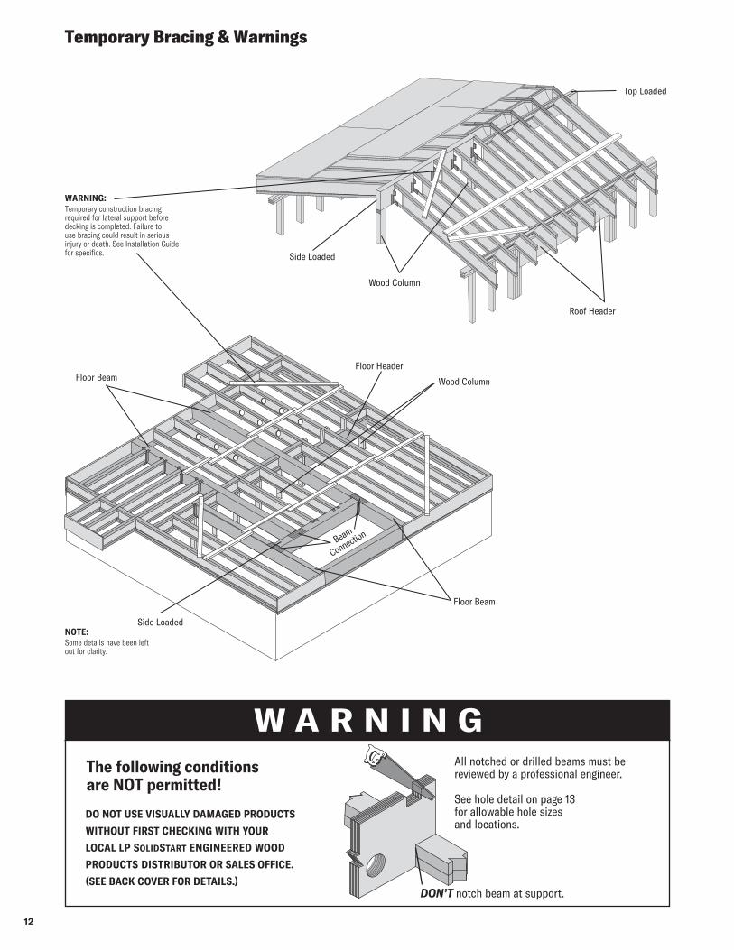
Temporary Bracing & Warnings
Side Loaded
Top Loaded
Roof Header
Wood Column
Floor Beam
Beam
Connection
Floor Header
NOTE:Some details have been left out for clarity.
WARNING:Temporary construction bracing required for lateral support before decking is completed. Failure to use bracing could result in serious injury or death. See Installation Guide for specifics.
Wood Column
Side Loaded
Floor Beam
DO NOT USE VISUALLY DAMAGED PRODUCTS
WITHOUT FIRST CHECKING WITH YOUR
LOCAL LP SolidStart ENGINEERED WOOD
PRODUCTS DISTRIBUTOR OR SALES OFFICE.
(SEE BACK COVER FOR DETAILS.)DON’T notch beam at support.
W A R N I N GAll notched or drilled beams must be reviewed by a professional engineer. See hole detail on page 13 for allowable hole sizes and locations.
The following conditions are NOT permitted!
13
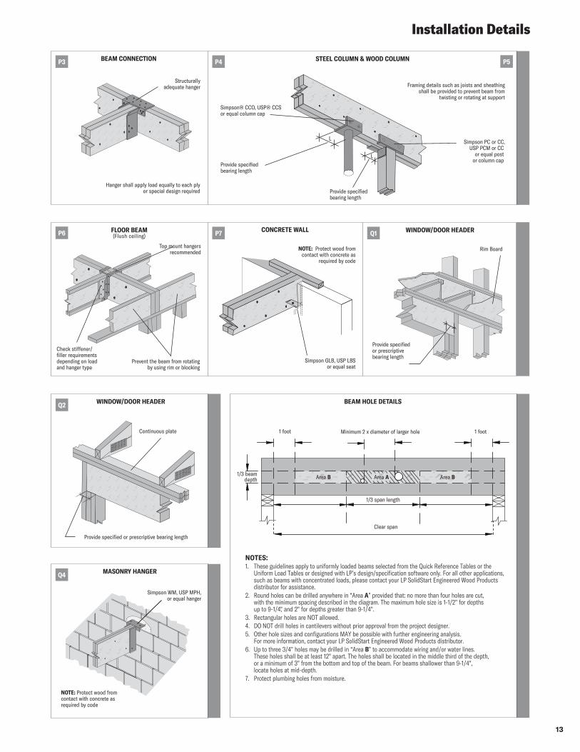
Installation Details
NOTES:1. These guidelines apply to uniformly loaded beams selected from the Quick Reference Tables or the
Uniform Load Tables or designed with LP’s design/specification software only. For all other applications, such as beams with concentrated loads, please contact your LP SolidStart Engineered Wood Products distributor for assistance.
2. Round holes can be drilled anywhere in “Area A” provided that: no more than four holes are cut, with the minimum spacing described in the diagram. The maximum hole size is 1-1/2" for depths up to 9-1/4," and 2" for depths greater than 9-1/4".
3. Rectangular holes are NOT allowed.4. DO NOT drill holes in cantilevers without prior approval from the project designer.5. Other hole sizes and configurations MAY be possible with further engineering analysis.
For more information, contact your LP SolidStart Engineered Wood Products distributor.6. Up to three 3/4" holes may be drilled in “Area B” to accommodate wiring and/or water lines.
These holes shall be at least 12" apart. The holes shall be located in the middle third of the depth, or a minimum of 3" from the bottom and top of the beam. For beams shallower than 9-1/4", locate holes at mid-depth.
7. Protect plumbing holes from moisture.
BEAM HOLE DETAILS
1/3 beam depth
1 foot Minimum 2 x diameter of larger hole 1 foot
1/3 span length
Clear span
Area AArea B Area B
MASONRY HANGER
Simpson WM, USP MPH, or equal hanger
NOTE: Protect wood from contact with concrete as required by code
Q4
Continuous plate
Provide specified or prescriptive bearing length
WINDOW/DOOR HEADERQ2
STEEL COLUMN & WOOD COLUMN
Simpson® CCO, USP® CCS or equal column cap
Simpson PC or CC, USP PCM or CC
or equal post or column cap
Provide specified bearing length
Framing details such as joists and sheathing shall be provided to prevent beam from
twisting or rotating at support
L
L
Provide specified bearing length
P4 P5BEAM CONNECTION
Structurally adequate hanger
Hanger shall apply load equally to each ply or special design required
P3
CONCRETE WALL
Simpson GLB, USP LBS or equal seat
NOTE: Protect wood from contact with concrete as
required by code
P7FLOOR BEAM (Flush ceiling)
Top mount hangersrecommended
Check stiffener/ filler requirements depending on load and hanger type
Prevent the beam from rotating by using rim or blocking
P6 WINDOW/DOOR HEADERQ1
Rim Board
Provide specified or prescriptive bearing length
14
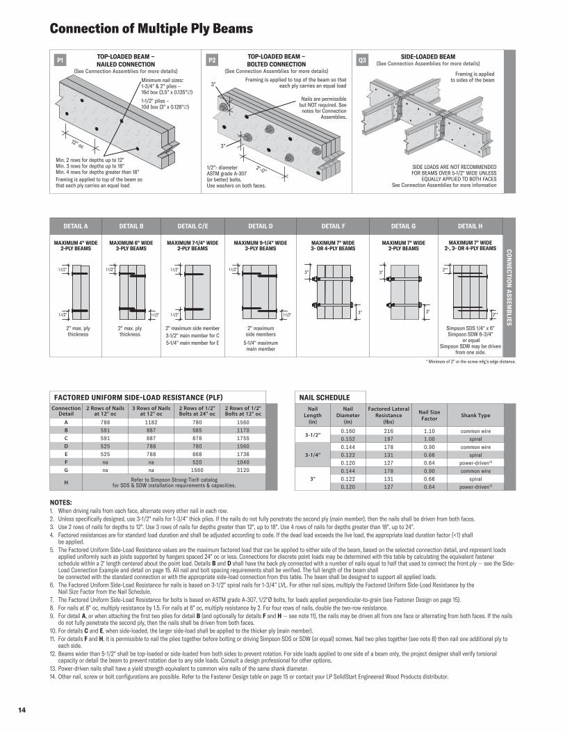
Connection of Multiple Ply Beams
NAIL SCHEDULENail
Length (in)
Nail Diameter
(in)
Factored Lateral Resistance
(lbs)
Nail Size Factor Shank Type
3-1/2"0.160 216 1.10 common wire0.152 197 1.00 spiral
3-1/4"0.144 178 0.90 common wire0.122 131 0.66 spiral0.120 127 0.64 power-driven13
3"0.144 178 0.90 common wire0.122 131 0.66 spiral0.120 127 0.64 power-driven13
FACTORED UNIFORM SIDE-LOAD RESISTANCE (PLF)Connection
Detail2 Rows of Nails
at 12" oc3 Rows of Nails
at 12" oc2 Rows of 1/2" Bolts at 24" oc
2 Rows of 1/2" Bolts at 12" oc
A 788 1182 780 1560B 591 887 585 1170C 591 887 878 1755D 525 788 780 1560E 525 788 868 1736F na na 520 1040G na na 1560 3120
H Refer to Simpson Strong-Tie® catalog for SDS & SDW installation requirements & capacities.
NOTES:1. When driving nails from each face, alternate every other nail in each row.2. Unless specifically designed, use 3-1/2" nails for 1-3/4" thick plies. If the nails do not fully penetrate the second ply (main member), then the nails shall be driven from both faces.3. Use 2 rows of nails for depths to 12". Use 3 rows of nails for depths greater than 12", up to 18". Use 4 rows of nails for depths greater than 18", up to 24".4. Factored resistances are for standard load duration and shall be adjusted according to code. If the dead load exceeds the live load, the appropriate load duration factor (<1) shall
be applied.5. The Factored Uniform Side-Load Resistance values are the maximum factored load that can be applied to either side of the beam, based on the selected connection detail, and represent loads
applied uniformly such as joists supported by hangers spaced 24" oc or less. Connections for discrete point loads may be determined with this table by calculating the equivalent fastener schedule within a 2' length centered about the point load. Details B and D shall have the back ply connected with a number of nails equal to half that used to connect the front ply — see the Side-Load Connection Example and detail on page 15. All nail and bolt spacing requirements shall be verified. The full length of the beam shall be connected with the standard connection or with the appropriate side-load connection from this table. The beam shall be designed to support all applied loads.
6. The Factored Uniform Side-Load Resistance for nails is based on 3-1/2" spiral nails for 1-3/4" LVL. For other nail sizes, multiply the Factored Uniform Side-Load Resistance by the Nail Size Factor from the Nail Schedule.
7. The Factored Uniform Side-Load Resistance for bolts is based on ASTM grade A-307, 1/2"Ø bolts, for loads applied perpendicular-to-grain (see Fastener Design on page 15).8. For nails at 8" oc, multiply resistance by 1.5. For nails at 6" oc, multiply resistance by 2. For four rows of nails, double the two-row resistance.9. For detail A, or when attaching the first two plies for detail B (and optionally for details F and H — see note 11), the nails may be driven all from one face or alternating from both faces. If the nails
do not fully penetrate the second ply, then the nails shall be driven from both faces.10. For details C and E, when side-loaded, the larger side-load shall be applied to the thicker ply (main member).11. For details F and H, it is permissible to nail the plies together before bolting or driving Simpson SDS or SDW (or equal) screws. Nail two plies together (see note 8) then nail one additional ply to
each side.12. Beams wider than 5-1/2" shall be top-loaded or side-loaded from both sides to prevent rotation. For side loads applied to one side of a beam only, the project designer shall verify torsional
capacity or detail the beam to prevent rotation due to any side loads. Consult a design professional for other options.13. Power-driven nails shall have a yield strength equivalent to common wire nails of the same shank diameter.14. Other nail, screw or bolt configurations are possible. Refer to the Fastener Design table on page 15 or contact your LP SolidStart Engineered Wood Products distributor.
DETAIL A DETAIL B DETAIL C/E DETAIL D DETAIL F DETAIL G DETAIL H
CO
NN
ECTIO
N A
SSEMB
LIES
MAXIMUM 9-1/4" WIDE 3-PLY BEAMS
1-1/2"
1-1/2"
1-1/2"
MAXIMUM 6" WIDE 3-PLY BEAMS
1-1/2"
1-1/2"
MAXIMUM 4" WIDE 2-PLY BEAMS
2" max. ply thickness
1-1/2"
1-1/2"
2" max. ply thickness
MAXIMUM 7-1/4" WIDE 2-PLY BEAMS
1-1/2"
3"
3"
3"
3"2"*
2"*
Simpson SDS 1/4" x 6" Simpson SDW 6-3/4"
or equalSimpson SDW may be driven
from one side.
MAXIMUM 7" WIDE 3- OR 4-PLY BEAMS
MAXIMUM 7" WIDE 2-PLY BEAMS
MAXIMUM 7" WIDE 2-, 3- OR 4-PLY BEAMS
2" maximum side members
5-1/4" maximum main member
2" maximum side member3-1/2" main member for C5-1/4" main member for E
TOP-LOADED BEAM – BOLTED CONNECTION
(See Connection Assemblies for more details)
Framing is applied to top of the beam so that each ply carries an equal load3"
Nails are permissible but NOT required. See
notes for Connection Assemblies.
3"
2'-0"1/2"- diameter ASTM grade A-307 (or better) bolts. Use washers on both faces.
SIDE-LOADED BEAM(See Connection Assemblies for more details)
SIDE LOADS ARE NOT RECOMMENDED FOR BEAMS OVER 5-1/2" WIDE UNLESS
EQUALLY APPLIED TO BOTH FACESSee Connection Assemblies for more information
Framing is applied to sides of the beam
TOP-LOADED BEAM – NAILED CONNECTION
(See Connection Assemblies for more details)
P1 P2 Q3
Min. 2 rows for depths up to 12"Min. 3 rows for depths up to 18"Min. 4 rows for depths greater than 18"
Minimum nail sizes:1-3/4" & 2" plies – 16d box (3.5" x 0.135"∅)
1-1/2" plies – 10d box (3" x 0.128"∅)
12" oc
Framing is applied to top of the beam so that each ply carries an equal load
* Minimum of 2" or the screw mfg.’s edge distance.
15
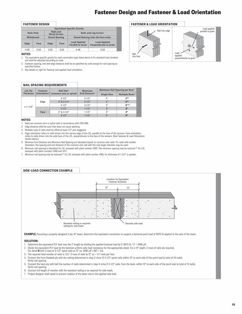
Fastener Design and Fastener & Load Orientation
NAIL SPACING REQUIREMENTS
LVL Ply Thickness
Fastener Orientation4
Nail Size1
(common wire or spiral)Minimum
End Distance5
Minimum Nail Spacing per Row5
Single Row Multiple Rows3
≥ 1-1/2"
Edge2-1/2" 2-1/2" 4" 4"6
3" & 3-1/4" 2-1/2" 4" 5"6
3-1/2" 3-1/2" 5" 6" 6,7
Face2-1/2" 1-1/2" 3" 3"
3" & 3-1/4" 1-1/2" 3" 3"3-1/2" 1-1/2" 5" 5"
NOTES:1. The equivalent specific gravity for each connection type listed above is for standard load duration
and shall be adjusted according to code.2. Fastener spacing, end and edge distance shall be as specified by code except for nail spacing as
specified below.3. See details to right for fastener and applied load orientation.
NOTES:1. Nails are common wire or spiral nails in accordance with CSA O86. 2. Edge distance shall be such that does not cause splitting.3. Multiple rows of nails shall be offset at least 1/2" and staggered.4. Edge orientation refers to nails driven into the narrow edge of the LVL, parallel to the face of the veneers. Face orientation
refers to nails driven into the wide face of the LVL, perpendicular to the face of the veneers. (See Fastener & Load Orientation details above.)
5. Minimum End Distance and Minimum Nail Spacing are tabulated based on common wire nails. For nails with smaller diameters, the spacing and end distance of the common wire nail with the next larger diameter may be used.
6. Minimum nail spacing is tabulated for LVL stamped with plant number 1089. The minimum spacing may be reduced 1" for LVL stamped with plant numbers 1066 and 1071.
7. Minimum nail spacing may be reduced 1" for LVL stamped with plant number 1089, for thickness of 1-3/4" or greater.
FASTENER & LOAD ORIENTATION
Nail into edge
Nail into face
Load applied parallel to grain
Load applied perpendicular to grain
SIDE-LOAD CONNECTION EXAMPLE
EXAMPLE: Assuming a properly designed 3-ply 14" beam, determine the equivalent connection to support a factored point load of 6970 lb applied to the side of the beam.
SOLUTION: 1. Determine the equivalent PLF load over the 2' length by dividing the applied factored load by 2: 6970 lb / 2' = 3485 plf.2. Divide the equivalent PLF load by the factored uniform side-load resistance for the appropriate detail. For a 14" depth, 3 rows of nails are required.
For detail B with 3 rows of 3-1/2" spiral nails at 12" oc: 3485 plf / 887 = 3.9.3. The required total number of nails is: 3.9 * 3 rows of nails @ 12" oc = 11.7 nails per foot.4. Connect the front (loaded) ply with the nailing determined in step 3: drive 12 3-1/2" spiral nails within 12" to each side of the point load (a total of 24 nails).
Verify nail spacing.5. Connect the back ply with half the number of nails determined in step 4: drive 6 3-1/2" nails, from the back, within 12" to each side of the point load (a total of 12 nails).
Verify nail spacing.6. Connect full length of member with the standard nailing or as required for side loads.7. Project designer shall detail to prevent rotation of the beam due to the applied side load.
12" 12"
Location for Equivalent Fastener Schedule
Standard nailing or required nailing for side loads
Discrete side load
FASTENER DESIGNEquivalent Specific Gravity
Nails Only Nails and Wood Screws Bolts and Lag Screws
Withdrawal Dowel Bearing Dowel Bearing (into the face only)
Edge Face Edge Face Load Applied Parallel to Grain
Load Applied Perpendicular to Grain
0.46 0.50 0.50 0.50 0.46 0.50
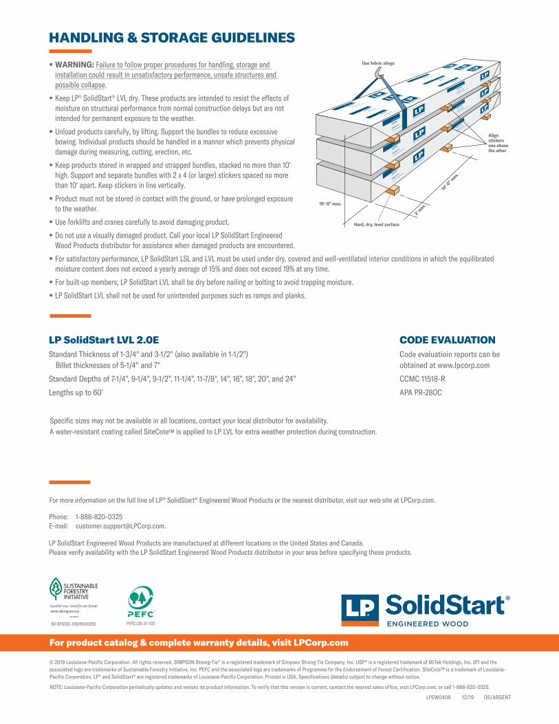
LP SolidStart LVL 2.0EStandard Thickness of 1-3/4" and 3-1/2" (also available in 1-1/2") Billet thicknesses of 5-1/4" and 7"
Standard Depths of 7-1/4", 9-1/4", 9-1/2", 11-1/4", 11-7/8", 14", 16", 18", 20", and 24"
Lengths up to 60'
© 2019 Louisiana-Pacific Corporation. All rights reserved. SIMPSON Strong-Tie® is a registered trademark of Simpson Strong-Tie Company, Inc. USP® is a registered trademark of MiTek Holdings, Inc. SFI and the associated logo are trademarks of Sustainable Forestry Initiative, Inc. PEFC and the associated logo are trademarks of Programme for the Endorsement of Forest Certification. SiteCote™ is a trademark of Louisiana-Pacific Corporation. LP® and SolidStart® are registered trademarks of Louisiana-Pacific Corporation. Printed in USA. Specifications (details) subject to change without notice.
NOTE: Louisiana-Pacific Corporation periodically updates and revises its product information. To verify that this version is current, contact the nearest sales office, visit LPCorp.com, or call 1-888-820-0325.
LPEW0408 12/19 OS/ARGENT
Specific sizes may not be available in all locations, contact your local distributor for availability. A water-resistant coating called SiteCote™ is applied to LP LVL for extra weather protection during construction.
CODE EVALUATIONCode evaluatioin reports can be obtained at www.lpcorp.com
CCMC 11518-R
APA PR-280C
For more information on the full line of LP® SolidStart® Engineered Wood Products or the nearest distributor, visit our web site at LPCorp.com.
Phone: 1-888-820-0325E-mail: [email protected].
LP SolidStart Engineered Wood Products are manufactured at different locations in the United States and Canada. Please verify availability with the LP SolidStart Engineered Wood Products distributor in your area before specifying these products.
PEFC/29-31-102BV-SFICOC-US09000262
For product catalog & complete warranty details, visit LPCorp.com
HANDLING & STORAGE GUIDELINES
Use fabric slings
Align stickers one above the other
Hard, dry, level surface
10'-0" max.
3' max.
10'-0
" max.
§ WARNING: Failure to follow proper procedures for handling, storage and installation could result in unsatisfactory performance, unsafe structures and possible collapse.
§ Keep LP® SolidStart® LVL dry. These products are intended to resist the effects of moisture on structural performance from normal construction delays but are not intended for permanent exposure to the weather.
§ Unload products carefully, by lifting. Support the bundles to reduce excessive bowing. Individual products should be handled in a manner which prevents physical damage during measuring, cutting, erection, etc.
§ Keep products stored in wrapped and strapped bundles, stacked no more than 10' high. Support and separate bundles with 2 x 4 (or larger) stickers spaced no more than 10' apart. Keep stickers in line vertically.
§ Product must not be stored in contact with the ground, or have prolonged exposure to the weather.
§ Use forklifts and cranes carefully to avoid damaging product.
§ Do not use a visually damaged product. Call your local LP SolidStart Engineered Wood Products distributor for assistance when damaged products are encountered.
§ For satisfactory performance, LP SolidStart LSL and LVL must be used under dry, covered and well-ventilated interior conditions in which the equilibrated moisture content does not exceed a yearly average of 15% and does not exceed 19% at any time.
§ For built-up members, LP SolidStart LVL shall be dry before nailing or bolting to avoid trapping moisture.
§ LP SolidStart LVL shall not be used for unintended purposes such as ramps and planks.


![[LSD]Remembrances of LSD Therapy Past-Betty Grover Eisner, org](https://img.pdfslide.net/doc/110x75/577dab601a28ab223f8c57f0/lsdremembrances-of-lsd-therapy-past-betty-grover-eisner-org.jpg)