Embed Size (px)
Citation preview

ZA3
DocumentazioneTecnica
S13rev. 3.107/2004© CAME
CANCELLIAUTOMATICI
CANCELLI AUTOMATICI
SERIE Z | Z SERIES | SERIE Z
SCHEDA COMANDOCONTROL BOARDTARJETA DE MANDO
319S13-1ITA
LIA
NO
/EN
GL
ISH/E
SP
AÑ
OL
IT
AL
IA
NO
—E
NG
LI
SH
—E
SP
AÑ
OL
QUADRO COMANDO
FUSIBILI LINEA 5A
ZA3
CH1
AF
FUSIBILECENTRALINA
3,15 A
T.L. T.C.A. TR2M.�1 3 4 5 6 7 8 9 10O
NCH2
DESCRIPTION OF CONTROL BOARD
The ZA3 electric board is suitable forcontrolling the automation of ATI, FERNI,KRONO, FAST and FROG series 230Vswing gates with up to 600W power and50-60Hz frequency. Wholly designedand built by CAME Cancelli AutomaticiS.p.A.The board is inserted and fixed to theABS case (S4339 o S4340), which hasan IP54 protection level, with airrecycling inlet and transformer.The board requires 230V (a.c.) atterminal blocks L1-L2 and the inlet isprotected with two 5A fuses. A 3.15Afuse protects the low voltage commanddevices.I he accessories’ total wattage to 24Vmust not exceed 20W.
DESCRIPCIÓN TARJETA DE MANDO
La tarjeta eléctrica ZA3 es adecuadapara el accionamiento de automa-tizaciones para puertas de batiente dela serie ATI, FERNI, KRONO, FAST yFROG, alimentadas a 230V, con poten-cia de hasta 600W, frecuencia 50÷60Hz.Diseñada y fabricada completamen-te por CAME Cancelli AutomaticiS.p.A.. La tarjeta se instala y fija enuna caja de ABS (S4339 o S4340) congrado de protección IP54, con tomapara recirculación de aire y transfor-mador.La tarjeta se alimenta con tensión a230V (c.a.) en los bornes L1-L2 y estáprotegida en entrada con dos fusiblesde línea de 5A. Los dispositivos demando son de baja tensión y estánprotegidos con fusible de 3.15A.La potencia total de los accesoriosde 24V no debe superar los 20W.
CARATTERISTICHE GENERALI GENERAL CHARACTERISTICS CARACTERISTICAS GENERALES
DESCRIZIONE SCHEDA COMANDO
La scheda elettrica ZA3 è adatta alcomando di automazioni per cancellia battente della serie ATI, FERNI,KRONO, FAST e FROG, alimentati a230V con potenza fino a 600W,frequenza 50÷60 Hz. Progettata ecostruita interamente dalla CAMECancelli Automatici S.p.A. La scheda va inserita e fissata nelcontenitore in ABS (S4339 o S4340)con grado di protezione IP54, dotatodi presa per il riciclo d’aria ecompleto di trasformatore.La scheda va alimentata contensione di 230V (a.c.) sui morsettiL1-L2 e protetta in ingresso con duefusibili di linea da 5A. I dispositivi dicomando sono a bassa tensione eprotetti con fusibile da 3.15A.La potenza complessiva degliaccessori a 24V non deve superarei 20W.
ENGLISH ESPANOLITALIANO

-2-
IT
AL
IA
NO
—E
NG
LI
SH
—E
SP
AÑ
OL SAFETY
Photocells can be connected to obtain:- Re-opening during closure (2-C1), ifthe photocells identify an obstacle whilethe gate is closing, they will reverse thedirection of movement until the gate iscompletely open;- Re-closing during opening (2-CX, dip8OFF-100OFF), if the photocells identifan obstacle while the gate is openinig,they will reverse the direction ofmovement until the gate is copletelyclosed;- Partial stop, shutdown of moving gate,with activation of an automatic closingcycle (2-CX);- Total stop (1-2), shutdown of gatemovement without automatic closing; apushbutton or radio remote control mustbe actuated to resume movement).NB: If an NC safety contact (2-C1, 2-CX,1-2) is opened, the LED will flash toindicate this fact.
ACCESSORIES WHICH CAN BE CONNECTED
TO THIS UNIT
-“Gate open” signal light (10-5);- Cycle lamp. The lamp which lights themanoeuvring zone: it remains lit from themoment the doors begin to open untilthey are completely closed (including thetime required for the automatic closure).In case automatic closure is not enabled,the lamp remains lit only dur ingmovement (E-E3);- Electric lock (11-S);
OTHER FUNCTIONS AVAILABLE
- Automatic closing.The automatic closing timer isautomatically activated at the end of theopening cycle. The preset, adjustableautomatic closing time is automaticallyinterrupted by the activation of any safetysystem, and is deactivated after a STOPcommand or in case of power failure;
SICUREZZA
Le fotocellule possono esserecollegate e predisposte per:- Riapertura in fase di chiusura (2-C1),le fotocellule rilevando un ostacolodurante la fase di chiusura delcancello, provocano l'inversione dimarcia fino alla completa apertura;- Richiusura in fase di apertura (2-CX,dip 8OFF-10OFF), le fotocellulerilevando un ostacolo durante la fasedi apertura del cancello, provocanol'inversione di marcia fino allacompleta chiusura;- Stop parziale, arresto del cancellose in movimento con conseguentepredisposizione alla chiusuraautomatica (2-CX, dip 8OFF-10ON);- Stop totale (1-2), arresto del cancellocon l'esclusione del ciclo di chiusuraautomatica; per riprendere ilmovimento bisogna agire sullapulsantiera o sul radiocomando;Nota: Se un contatto di sicurezzanormalmente chiuso (2-C1, 2-CX, 1-2)si apre, viene segnalato dal lampeggiodel LED segnalazione.
ACCESSORI COLLEGABILI
- Lampada di segnalazione "cancelloaperto" (10-5);- Lampada ciclo 60W max. Lampadache illumina la zona di manovra,rimane accesa dal momento in cui leante iniziano l'apertura fino allacompleta chiusura (compreso il tempodi chiusura automatica). Nel caso nonvenga inserita la chiusura automaticarimane accesa solo durante ilmovimento (E-E3);- Elettroserratura (11-S);
ALTRE FUNZIONI
- Chiusura automatica.Il temporizzatore di chiusuraautomatica si autoalimenta a fine-tempo corsa in apertura. Il tempoprefissato regolabile, è comunquesubordinato dall'intervento dieventuali accessori di sicurezza e siesclude dopo un intervento di "stop"o in mancanza di energia elettrica;
SEGURIDAD
Las fotocélulas pueden estarconectadas y predispuestas para:- Reapertura en la fase de cierre (2-C1), las fotocélulas detectan unobstáculo durante el cierre de lapuerta, provocando la inversión demarcha hasta la apertura completa;- Recierre en la fase de apertura (2-CX, dip 8 OFF-10OFF), las fotocélulasdetectan un obstàculo durante laaperture de la puerta, provocando lainversiòn de marcha hasta el cierrecompleto;- Parada parcial, parada de la puertasi se encuentra en movimiento con laconsiguiente predisposición al cierreautomático (2-CX);- Parada total (1-2), parada de lapuerta excluyendo el posible ciclo decierre automático; para reactivar elmovimiento es preciso actuar en elteclado o en el mando a distancia);Nota: La apertura de un contacto deseguridad normalmente cerrado (2-C1, 2-CX, 1-2) es señalada por mediodel destello del LED de señalización.
ACCESORIOS CONECTABLES
- Lámpara de señal de “puertaabierta” (10-5);- Lámpara ciclo. Lámpara quealumbra la zona de maniobra: sequeda encendida a partir delmomento en que las hojas empiezanla apertura hasta el cierre completo(incluyendo el tiempo de cierreautomático). Si no se habilita el cierreautomático, el cierre permaneceencendido sólo durante elmovimiento (E-E3).- Cerradura eléctrica (11-S);
OTRAS FUNCIONES SELECCIONABLES
- Cierre automático.El temporizador de cierre automático seautoalimenta en fin-de-tiempo carreraen fase de apertura. El tiempo prefijadoregulable, sin embargo, estásubordinado a la intervención deposibles accesorios de seguridad y seexcluye después de una intervenciónde parada o en caso de falta de energíaeléctrica;

-3-
IT
AL
IA
NO
—E
NG
LI
SH
—E
SP
AÑ
OL
- Obstacle presence detection:When the motor is stopped (gate isclosed, open or half-open after anemergency stop command), thetransmitter and the control pushbuttonwill be deactivated if an obstacle isdetected by one of the safety devices (forexample, the photocells);- Hammer movement. At every openingcommand, the wings press the closingstop-ledge for a second, thus facilitatingthe release operation of the electric lockconnected to terminals 11-S.It is only active if the wings are closedand at the end of the work time or at the1st manoeuvre after the system has beenpowered;- Enabling functions of partial stop or re-closure during opening, normally-closedcontact (2-CX), select one of the twofunctions by setting Dip (see page 14);-"Ingedrukte knop" function: Gateoperates only when the pushbutton isheld down (the radio remote controlsystem is deactivated);- Partial opening, second motor dooropening, adjusted with TR2M trimmer; itis activated by collecting to theterminals 2-3P;- Pre-flashing for 5 seconds, while thedoor is opening and closing;- Type of command:-open-stop-close-stop for pushbuttonand radio transmitter;-open-close-reverse for pushbutton andradio transmitter;-open only for radio transmitter.
ADJUSTMENTS
- Automatic closure time;- Partial opening time and delay inclosing of the M2 motor;-Operating time
- Detección de presencia obstáculo.Con el motor parado (puerta cerrada,abierta o en posición semi-abiertaobtenida a través de un comando destop total), anula cualquier funcióndel transmisor o del botón en casode obstáculo detectado por losdispositivos de seguridad (porejemplo: fotocélulas);- Golpe de ariete. Cada vez que se daun mando de apertura, las hojaspresionan en el tope de cierre por unsegundo, facilitando la operación dedesenganche de la cerraduraeléctrica conectada en los bornes 11-S.Está activo sólo si las hojas estáncerradas y al final del tiempo defuncionamiento, o bien en la 1a
maniobra tras haber conectado latensión a la instalación;- Habilitación para las funciones deparada parcial o cierre durante laapertura, contacto normalmentecerrado (2-CX), selecionar una de lasdos funciones mediante Dip (ver pág.14);- Función a "Acción mantenida".Funcionamiento de la puertamanteniendo pulsada la tecla(excluye la función del mando adistancia);- Apertura parcial, apertura de la hojadel segundo motor, reguladamediante trimmer TR2M; se activamediante lo bornes 2-3P;- Preintermitencia de 5 segundostanto en el momento de aperturacomo de cierre de la puerta;- Tipo de mando;-apertura-parada-cierre-parada paratecla y transmisor de radio;-apertura-cierre-inversión para teclay transmisor de radio;-sólo apertura para transmisor deradio.
REGULACIONES
-Tiempo cierre automàtico;-Tiempo de apertura parcial yretardoen el cierre del motor M2;-Tiempo trabajo.
- Rilevazione di presenza ostacolo.A motore fermo (cancello chiuso,aperto o dopo un comando di stoptotale), impedisce qualsiasimovimento se i dispositivi di sicurezza(es. fotocellule) rilevano un ostacolo;- Colpo d’ariete. Ad ogni comando diapertura, le ante premono in battutadi chiusura per un secondo,facilitando l’operazione di sganciodell’elettroserratura collegata suimorsetti 11-S.É attivo solo se le ante sono chiuse ea fine tempo lavoro, oppure alla 1a
manovra dopo aver dato tensioneall’impianto.- Abilitazione alle funzioni di stopparziale o richiusura durantel'apertura, contatto normalmentechiuso (2-CX), selezionare una delledue funzioni tramite dip (vedi pag.14);- Funzione a "azione mantenuta".Funzionamento del cancellomantenendo premuto il pulsante(esclude la funzione delradiocomando);- Apertura parziale, apertura dell'antadel secondo motore, regolata tramitetrimmer TRM2, viene attivatacollegandosi ai morsetti (2-3P);- Prelampeggio di 5 secondi sia inapertura che in chiusura delle ante;-Tipo di comando:-apre-stop-chiude-stop con pulsantee/o trasmettitore;-apre-chiude-inversione con pulsantee/o trasmettitore;-solo apre per trasmettitore.
REGOLAZIONI
- Tempo chiusura automatica;- Tempo apertura parziale e ritardochiusura del 2° motore;- Tempo lavoro.
Attenzione! Prima di intervenireall’interno dell’apparecchiatura,togliere la tensione di linea.
Important! Disconnect the unit fromthe main power lines before carrying outany operation inside the unit.
¡Atención! Antes de actuardentro del aparato, quitar la tensiónde línea.
-4-
IT
AL
IA
NO
—E
NG
LI
SH
—E
SP
AÑ
OL
1 2 3 4L2T L1T
0 2412
QUA DRO COMANDO
FUSIBILI LINEA 5A
ZA3
CH1
AF
FUSIBILECENTRALINA
3,15 A
T.L. T.C.A. TR2M.�1 3 4 5 6 7 8 9 10O
NCH2
8 9 7 5 644444
12
3
2
10
1
11
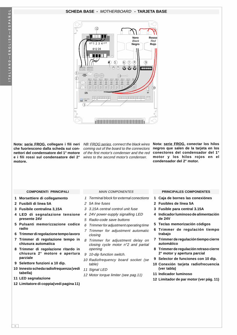
SCHEDA BASE - MOTHERBOARD - TARJETA BASE
COMPONENTI PRINCIPALI
1 Morsettiere di collegamento
2 Fusibili di linea 5A
3 Fusibile centralina 3,15A
4 LED di segnalazione tensionepresente 24V
5 Pulsanti memorizzazione codiceradio
6 Trimmer di regolazione tempo lavoro
7 Trimmer di regolazione tempo inchiusura automatica
8 Trimmer di regolazione ritardo inchiusura 2° motore e aperturaparziale
9 Selettore funzioni a 10 dip.
10 Innesto scheda radiofrequenza (veditabella)
11 LED segnalazione
12 Limitatore di coppia(vedi pagina 11)
MAIN COMPONENTES
1 Terminal block for external conections
2 5A line fuses
3 3.15A central control unit fuse
4 24V power-supply signalling LED
5 Radio-code save buttons
6 Trimmer for adjustment operating time
7 Trimmer for adjustment automaticclosing
8 Trimmer for adjustment delay onclosing cycle motor n°2 and partialopening
9 10-dip function switch.
10 Radiofrequency board socket (setable)
11 Signal LED
12 Motor torque limiter (see pag.11)
PRINCIPALES COMPONENTES
1 Caja de bornes las conexiónes
2 Fusibles de línea 5A
3 Fusible para central 3.15A
4 Indicador luminoso de alimentaciónde 24V
5 Teclas memorización códigos
6 Trimmer de regulación tiempotrabajo
7 Trimmer de regulación tiempo cierreautomático
8 Trimmer de regulación retraso cierre2° motor y apertura parcial
9 Selector de funciones con 10 dip.
10 Conexión tarjeta radiofrecuencia(ver tabla)
11 Indicador luminoso
12 Limitador de par motor (ver pág. 11)
Nota: serie FROG, collegare i fili neriche fuoriescono dalla scheda sui con-nettori del condensatore del 1° motoree i fili rossi sul condensatore del 2°motore.
Nota: serie FROG, conectar los hilosnegros que salen de la tarjeta en losconectores del condensador del 1°motor y los hilos rojos en elcondensador del 2° motor.
NB: FROG series, connect the black wirescoming out of the board to the connectorsof the first motor’s condenser and the redwires to the second motor’s condenser.
RossoRedRojo
NeroBlackNegro

-5-
IT
AL
IA
NO
—E
NG
LI
SH
—E
SP
AÑ
OL
QUADRO COMANDO
FUSIBILI LINEA 5A
ZA3
CH1
AF
FUSIBILECENTRALINA
2A
T.L. T.C.A. TR2M.�� � � � � � � ��
�
CH2
�� � � � � � � ��
�ONONONONON
T.L. T.C.A. TR2M.
QUADRO COMANDO
FUSIBILI LINEA 5A
ZA3
CH1
AF
FUSIBILECENTRALINA
2A
T.L. T.C.A. TR2M.�� � � � � � � ��
�
CH2
SELEZIONI FUNZIONI - SELECTION OF FUNCTIONS - SELECCIÓN DE LAS FUNCIONES
DIP-SWITCH 10 VIEDIP-SWITCH 10 VIEDIP-SWITCH 10 VIEDIP-SWITCH 10 VIEDIP-SWITCH 10 VIE / 10-WAY DIP-SWITCH ///// DIP-SWITCH 10 VÍASDIP-SWITCH 10 VÍASDIP-SWITCH 10 VÍASDIP-SWITCH 10 VÍASDIP-SWITCH 10 VÍAS
1 ON Chiusura automatica attivata;(1OFF-disattivata)
2 ON "Apre-stop-chiude-stop" conpulsante (2-7) e radiocomando(scheda AF inserita) attivata;
2 OFF "Apre-chiude" con pulsante (2-7)e radiocomando (scheda AFinserita) attivata;
3 ON "Solo apertura" con radiocomando (scheda AF inserita)attivata; (3OFF-disattivata)
4 ON Prelampeggio in apertura echiusura attivato; (4OFF- disat.)
5 ON Rilevazione presenza ostacoloattivato; (5OFF dis.)
6OFF "azione mantenuta" (esclude ilfunziona mento delradiocomando) disattivata; (6ON- attivata)
7 ON Colpo d'ariete attivato; (per facilitare lo sgancio della serratura)7OFF-disattivato
8 OFF - 10 OFF Funzione dirichiusura in fase di apertura(collegare il dispositivo disicurezza sui morsetti 2-CX)attivato;
8 OFF - 10 ON Funzione di stopparziale (collegare il dispositivodi sicurezza sui morsetti 2-CX)attivato;
(se non vengono utilizzati i dispositivi su2-CX, posizionare il dip 8 in ON)
9 OFF Funzione di riapertura in fase dichiusura attivato; con dispositivodi sicurezza collegato aimorsetti 2-C1, (se non vieneutilizzato il dispositivo,selezionare il dip in ON)
1 ON Automatic closure enabled; (1OFF-disabled)
2 ON "Open-stop-close-stop" with button(2-7) and radio control (AF boardinserted) enabled;
2 OFF "Open-close" with but ton (2-7) andradio control (AF board inserted)enabled;
3 ON "Only opening" with radio control(AF board inserted) enabled;
( 3OFF -disabled)
4 ON Pre-flashing (opening and closing)enabled; (4OFF-disabled)
5 ON Obstacle detection device enabled;(5OFF - disabled)
6 OFF "Maintained action" (radio remotecontrol is deactivated when function is selected) desabled; (6ON-enabled)
7 ON Hammer movement operationenabled; (this function helps unlockthe electric lock) 7OFF -disabled
8OFF - 10 OFF Re-closure during opening(connect the safety device on terminals (2-CX) enabled;
8OFF - 10 ON Partial stop (connect thesafety device on terminals (2-CX)enabled;
(if the devices on the 2-CXterminals are not used, set Dip 8 inON)
9 OFF Re-opening in closing phase(connect the safety device on terminals 2-C1) enabled; if not used, setthe dip- switch to ON.
1 ON Cierre automático activado;(1OFF-desactivado)
2 ON "Abrir-parada-cerrar- parada" conbotón (2-7) y radiocontrol (tarjetaAF conectada) activado;
2 OFF "Abrir-cerrar" con botón (2-7)yradiocontrol (tarjeta AF conec-tada) activado;
3 ON "Solo apertura" con radiocon-trol (tarjeta AF conectada) acti-vao; (3OFF-desactivado)
4 ON Pre-intermitencia en la fase deapertura y cierre activado; (4OFFdesactivado)
5 ON Detección del obstáculo activa-do; (5OFF- desacti.)
6 OFF "blijvende interventie" (escluyela función del mando de radio)des activado; (6ON - activado)
7 ON Golpe de ariete activado; (estafunción sirve para agilizar desenganche de la electrocerradu-ra). 7OFF-desacti.)
8OFF - 10 OFF Recierre durante la aper-tura (conecte el dispositivo deseguridad a los bornes 2-CX)activado;
8OFF - 10 ON Parada par cial (conecte eldispositivo de seguridad a losbornes 2-CX) activado;
(si no utiliza los dispositivos en2-CX, coloque el dip 8 en ON)
9 OFF Reapertura en la fase de cierre(conecte el dispositivo de segu-ridad a los bornes 2-C1) activado;si no se utiliza, poner el dip en ON
REGOLAZIONI - ADJUSTMENTS - REGULACIONES
Trimmer T.L. = Adjusts of operating timefrom a minimum of 0” to a maximum of 120”.Trimmer T.C.A. = Adjusts automatic closingtime from a minimum of 1” to a maximum of120”.Trimmer TR2M = Adjustment delay duringclosure of 2nd motor (min. 0”, max. 15”) andsimultaneously partial opening time (min. 0”,max. 30”).
Trimmer T.L. = Regolazione tempo di la-voro da un minimo di 0” a un massimo di120”.Trimmer T.C.A. = Regolazione tempo dichiusura automatica da un minimo di 1” aun massimo di 120”.Trimmer TR2M = Regolazione ritardo inchiusura 2° motore (min. 0”, max. 15”) econtemporaneamente apertura parziale(min. 0”, max. 30”).
Trimmer T.L. = Regulación tiempo de tra-bajo, desde un mínimo de 0” hasta unmáximo de 120”.Trimmer T.C.A. = Regulación tiempo decierre automático, desde un mínimo de 1”hasta un máximo de 120”.Trimmer TR2M = Regulación del retardodurante el cierre del 2° motor (min. 0”,máx. 15”) y contemporáneamente apertu-ra parcial (min. 0”, máx. 30”).
TRIMMERS ADJUSTMENT
REGULACIÓN TRIMMERS
REGOLAZIONE TRIMMERS

-6-
IT
AL
IA
NO
—E
NG
LI
SH
—E
SP
AÑ
OL
� � � � � � � � �� � �� � � � � �� � � � � ���� ����
WWWWW
EEEEE
L1L1L1L1L1
L2L2L2L2L2
UUUUUWWWWWVVVVV
XXXXXWWWWWYYYYY
E E E E E
E3E3E3E3E3
1010101010
5 5 5 5 5
1010101010
1111111111
11 11 11 11 11
S S S S S
1 1 1 1 1
2 2 2 2 2
COLLEGAMENTI ELETTRICI - ELECTRICAL CONNECTIONS - CONEXIONES ELÉCTRICAS
Alimentazione quadro comando - 230V (a.c.)Power supply for control unit - 230V (a.c.)Alimentación cuadro de mando - 230V (a.c.)
Collegamento 1 Motore (ritardato in apertura)Connection for 1 motor (delayed in opening)Conexionado 1 motor (redardo en apertura)
Collegamento 2 Motore (ritardato in chiusura)Connection for 2 motor (delayed in closing)Conexionado 2 motor (redardo en cierre)
Uscita 230V (a.c.)-25W max. in movimento (es. lampeggiatore)230V (a.c.)-25W max. output in motion (e.g. flashing light)Salida de 230V (a.c.) en movimiento (p.ej. conexión lámpara intermitente)
Nel caso si utilizzi un solo motore, col-legare solo il motore n°2 in uscitaX,W,Y.
If only one reduction gear is used, connectonly gear n°2 to the X,W,Y outlet.
Si se usa un sólo motor, conecte sóloel motor n°2 en la salida X,W,Y.
Collegamento lampada ciclo (230V-60W)Connection (230V-60W) cycle lampConexionado lámpara ciclo (230V-60W)
Lampada spia (24V-3W max.) "cancello aperto"(24V-3W max.) "gate-opened" signal lampLampara indicadora (24V-3W max.) "puerta abierta"
Uscita 24V (a.c.) alimentazione accessori (max 20W)24V (a.c.) output power supply to accessories (max. 20W)Salida 24V (a.c.) alimentación accesorios (max 20W)
Collegamento elettroserratura (12V-15W max.)Connection for electrically-actuated lock: 12V-15W max.Conexión electrocerradura (12V-15W max.)
Pulsante di stop (N.C.)Stop button (N.C.)Tecla de parada (N.C.)

-7-
IT
AL
IA
NO
—E
NG
LI
SH
—E
SP
AÑ
OL
B1B1B1B1B1
B2B2B2B2B2
�� � � � � � � � �
�
�� � � � � � � � �
�
8 OFF - 10 OFF
8 OFF - 10 ON
2 2 2 2 2
CXCXCXCXCX
22222
2 2 2 2 2
3P3P3P3P3P
22222
44444
22222
77777
2 2 2 2 2
C1C1C1C1C1
3
Contatto (N.C.) di richiusura durante l'aperturaContact (N.C.) for re-closing during openingContacto (N.C.) de recierre en la fase de apertura
Contatto (N.C.) stop parzialeContact (N.C.) partial stopContacto (N.C.) parada parcial
Collegamento antennaAntenna connectionConexión antena
Pulsante (N.O.) per apertura parziale (apertura del 2° motore)Pushbutton (normally open) partial opening (opens to motor no. 2)Tecla (N.O.) para apertura parcial (apertura del 2° motor)
Pulsante chiude (N.O.)(N.O.) Pushbutton-closePulsador de cierre (N.O.)
Collegamento radio e/o pulsante (N.O.) per comandi(vedi dip-switch 2-3 sel.funzioni)Contact radio and/or button for control(see dip-switch 2-3 function selection)Contacto radio y/o pulsador para mando(vedas dip-switch 2-3 seleción función)
Contatto (N.C.) di riapertura in fase di chiusurazContact (N.C.) for re-opening during closingContacto (N.C.) para la reapertura en la fase de cierre
Uscita contatto (N.O.) Portata contatto: 5A - 24V d.c.Contact output (N.O.) Resistive load: 5A - 24V d.c.Salida contacto (N.O.) Carga resistiva: 5A - 24V d.c.
Pulsante apre (N.O.)Open button (N.O.)Tecla de apertura (N.O.)

-8-
IT
AL
IA
NO
—E
NG
LI
SH
—E
SP
AÑ
OL
TOP TAM
AF
�� � � � � � � ��
�
1 2 3 4L2T L1T
0 2412
QUADRO COMANDO
FUSIBILI LINEA 5A
ZA3
CH1
AF
FUSIBILECENTRALINA
2A
T. L. T. C. A. TR2M.�� � � � � � � ��
�
CH2
1 2 3 4L2T L1T
0 2412
�� �� �� � �� ��
-PROCEDURA-
A. inserire una scheda AF.
B. codificare i trasmettitori.
C. memorizzare la codifica sulla schedabase.
-PROCEDURE-
A. insert an AF card.
B. encode transmitters.
C. store code in the motherboard.
-PROCEDIMIENTO-
A. introducir una tarjeta AF.
B. codificar los transmisores.
C. memorizar la codificación en la tarjetabase.
INSERIMENTO SCHEDA AF - AF BOARD INSERTION - MONTAJE DE LA TARJETA AF
La schedina AF deve essere inserita OB-BLIGATORIAMENTE in assenza di tensione, per-ché la scheda madre la riconosce solo quandoviene alimentata
The AF board should ALWAYS be insertedwhen the power is off because the motherboard onlyrecognises it when it is powered.
La tarjeta AF se debe montar OBLIGATO-RIAMENTE en caso de falta de corriente, por-que la tarjeta madre la reconoce sólo cuandoestá alimentada
A
LIMITATORE DI COPPIA MOTORE - MOTOR TORQUE LIMITER - LIMITADOR DE PAR MOTOR
Per variare la coppia motore, spostareil faston indicato su una delle 4 posizio-ni; 1 min, 4 max.
To vary the motor torque, move the indi-cated faston to one of the four positions:1=min, 4=max
Para variar el par motor, desplazar elfaston indicado hasta una de las 4 posi-ciones; 1 mín. 4 máx.
SCHEDA BASEMOTHERBOARDTARJETA BASE
SCHEDA "AF""AF" BOARDTARJETA «AF»
(**) Per trasmettitori con frequenza 433.92 AM (serie TOP e serie TAM)bisogna, sulla relativa scheda AF43S, posizionare il jumper come illustrato.
(**) On AM transmitters operating at 433.92 MHz (TOP and TAM series), positionthe jumper connection on circuit card AF43S as shown on the sheet.
(**) Para transmisores con frecuencia 433.92 AM (serie TOP y serie TAM) esnecesario, en la tarjeta corespondiente AF43S, colocar el jumper como seindica
Frequenza / MHz
Frequency / MHz
Frecuencia / MHz
Scheda radiofrequenza
Radiofrequency board
Tarjeta radiofrecuencia
Trasmettitore
Transmitter
Transmisor
FM 26.995 AF130 TFM
FM 30.900 AF150 TFM
AM 26.995 AF26 TOP
AM 30.900 AF30 TOP
AM 433.92AF43S / AF43SM TAM / TOP **
AF43SR ATOMO
INSTALLAZIONE DEL RADIOCOMANDO - RADIO CONTROL INSTALLATION - INSTALACIÓN DEL RADIOMANDO

-9-
IT
AL
IA
NO
—E
NG
LI
SH
—E
SP
AÑ
OL
TAM
T132T134T138
T152T154T158
T432T434T438
TFM
TOP
T432M - T312M
� � � � � � � � �
� � � �
C
D�� ��
P2
CH1 CH2 CH3 CH4
P1
CH1 CH2 CH3 CH4
� � � � � � � � � � � �� � � �
� � � � � � � � � � � � � � � �
T432S / T432SA /T434MA
AT01 - AT02 - AT04
ATOMO
T434M - T314M
P1=CH1P2=CH2P3=CH3P4=CH4
� � � � � � � � �
C
�� ��
� ��
CODIFICA TRASMETTITORI - TRANSMITTER ENCODING - CODIFICACIÓN TRANSMISORES
impostare il codice sul dip-switch C e il canale su D (P1=CH1 eP2=CH2, impostazione di default)
set the code to dip-switch C and channel to D (P1=CH1 and P2=CH2,default setting)
plantear el código en el dip-switch C y el canal en D (P1=CH1 yP2=CH2, planteamiento por defecto)
vedi istruzioni su confezionesee instructions on pack
ver instrucciones en el embalaje
vedi foglio istruzioni inserito nella confezionedella scheda AF43SR
see instruction sheet inside the pack of AF43SR circuit cardver hoja de instrucciones adjunta en el embalaje
de la tarjeta AF43SR
vedi foglio istruzioni inserito nella confezione
see instruction sheet inside thepack
ver hoja de instrucciones adjuntaen el embalaje
B
impostare solo il codiceset code only
plantear sólo el código

-10-
IT
AL
IA
NO
—E
NG
LI
SH
—E
SP
AÑ
OL
�
����
��
codice/code/codice1.
4.
J
2.
J
P1=OFF P2=ON
3.
T262M - T302M
�� ��
J
P1=CH1P2=CH2
fig. Afig. B
P1=CH1 - P2=CH4
P1=CH1 - P2=CH3 P1=CH3 - P2=CH2
P1=CH3 - P2=CH4
�� ��
� ��
P1=CH1 - P2=CH2P3=CH3 - P4=CH4
J
T264M - T304M
T2622M - T3022M
�
����
��
P1=CH1P2=CH2
1° codice/code/ codice2° codice/code/codice
�� ��
� ��
J
P3=CH1P4=CH2
J
CODIFICA TRASMETTITORI - TRANSMITTER ENCODING - CODIFICACIÓN TRANSMISORES
TOP QUARZATI - QUARTZ - CUARZO
premere in sequenza P1 o P2 per registrare ilcodice; al decimo impulso un doppio suono con-fermerà l'avvenuta registrazione
Press P1 or P2 in sequence in order to registerthe code; at the tenth pulse, a double beep willconfirm that registration has occurred
oprimir repetidamente P1 ó P2 para registrar elcódigo; con el décimo impulso un doble sonidoseñalará que el registro se ha efectuado.
PROCEDURA COMUNE DI CODIFICA
1. segnare un codice (anche perarchivio)
2. inserire jumper codifica J3. memorizzarlo4. disinserire jumper J
STANDARD ENCODING PROCEDURE
1. assign a code (also on file)2. connect encoding jumper J3. register code4. disconnect jumper J
PROCEDIMIENTO COMÚN DE CODIFICACIÓN
1. marcar un código (también parael archivo)
2. conectar un jumper codificación J3. registrar el código4. desconectar jumper J
CODIFICA TRASMETTITORI - TRANSMITTER ENCODING - CODIFICACIÓN TRANSMISORES
La prima codifica deve essere effettuata mantenendo i jumper po-sizionati per i canali 1 e 2 come da fig. A; per eventuali e successi-ve impostazioni su canali diversi vedi fig. B
The first encoding operation must be carried out whilst keeping thejumpers positioned for channels 1 and 2 as per fig. A; see fig. B forany subsequent settings on different channels.
La primera codificación tiene que efectuarse manteniendo los jum-per conectados para los canales 1 y 2 como se ilustra en la fig. A;para planteamientos posteriores en canales distintos ver la fig. B

-11-
IT
AL
IA
NO
—E
NG
LI
SH
—E
SP
AÑ
OL
� �
��
���� ������� �
CH1
AF
T.L. T.C.A.CH2
CH2CH2CH2CH2CH2
CH1CH1CH1CH1CH1
FIG. 2FIG. 2FIG. 2FIG. 2FIG. 2ABB. 2ABB. 2ABB. 2ABB. 2ABB. 2
FIG. 1FIG. 1FIG. 1FIG. 1FIG. 1ABB. 1ABB. 1ABB. 1ABB. 1ABB. 1
MEMORIZZAZIONE CODICE - CODE STORAGE - MEMORIZACIÓN CÓDIGO
Tenere premuto il tasto "CH1" sulla schedabase (il led di segnalazione lampeggia), conun tasto del trasmettitore si invia il codice, illed rimarrà acceso a segnalare l'avvenutamemorizzazione (vedi fig.1);-Eseguire la stessa procedura con il tasto"CH2" associandolo con un altro tasto deltrasmettitore (fig.2).CH1 = Canale per comandi diretti ad unafunzione della centralina del motoriduttore(comando "solo apre" / "apre-chiude-inver-sione" oppure "apre-stop-chiude-stop", aseconda della selezione effetuata sui dip-switch 2 e 3).CH2 = Canale per comandi diretti ad un di-spositivo accessorio collegato su B1-B2.N.B.: Se in seguito si vuol cambiare codice,basta ripetere la sequenza descritta.
-Keep the CH1 key pressed on the base card(the signal LED will flash), and with a key on thetransmitter the code is sent, the LED will remainlit to signal the successful saving of the code(figure 1);-Perform the same procedure with the CH2 key,associating it with another transmitter key(figure 2).CH1 = Channel for direct control of one functionperformed by the control unit on the gear motor("open only" / "open-close-reverse" or "open-stop-close-stop", depending on the position ofdip switches 2 and 3).CH2 = Channel for direct control of an accesso-ry connected across B1-B2.N.B. If you wish to change the code on yourtransmitters in the future, simply repeat theprocedure described above.
-Mantener oprimida la tecla "CH1" en la tarje-ta base (el led de señalización parpadea),con una tecla del transmisor se envía elcódigo, el led permanece encendido paraindicar que el almacenamendo se ha efectua-do (fig.1);-Efectuar el mismo procedimiento con latecla "CH2" asociándola a otra tecla del trans-misor (fig.2).CH1 = Canal para mando directo a una fun-ción de la central del motorreductor (mando"solo abre" / "abre-cierra-inversión" o "abre-stop-cierra-stop", según la selección efec-tuada en los dip-switch 2 y 3).CH2 = Canal para un mando directo a undispositivo accesorio conectado en B1-B2.Nota: Si posteriormente se quisiera cambiarel código de los propios transmisores, sólohay que repetir la secuencia descrita.
C
LED di segnalazioneLED di segnalazioneLED di segnalazioneLED di segnalazioneLED di segnalazione signal LED
LED de señalLED de señalLED de señalLED de señalLED de señal
Scheda radiofrequenza AFScheda radiofrequenza AFScheda radiofrequenza AFScheda radiofrequenza AFScheda radiofrequenza AFAF radiofrequency board
Tarjeta radiofrecuencia AFTarjeta radiofrecuencia AFTarjeta radiofrecuencia AFTarjeta radiofrecuencia AFTarjeta radiofrecuencia AF

CANCELLI AUTOMATICI
CAME LOMBARDIA S.R.L.______COLOGNO M. (MI) (+39) 02 26708293 (+39) 02 25490288
CAME SUD S.R.L. ___________________NAPOLI (+39) 081 7524455 (+39) 081 7529109
CAME (AMERICA) L.L.C.____________MIAMI (FL) (+1) 305 5930227 (+1) 305 5939823
CAME AUTOMATISMOS S.A__________MADRID (+34) 091 5285009 (+34) 091 4685442
CAME BELGIUM_NV-SA____________LESSINES (+32) 068333014 (+32) 068 338019
CAME FRANCE S.A.______NANTERRE CEDEX (PARIS) (+33) 01 46130505 (+33) 01 46130500
CAME GMBH__________KORNTAL BEI (STUTTGART) (+49) 07 11839590 (+49) 07 118395925
CAME GMBH_____________SEEFELD BEI (BERLIN) (+49) 03 33988390 (+49) 03 339885508
CAME PL SP.ZO.O_______________WARSZAWA (+48) 022 8365076 (+48) 022 8369920
CAME UNITED KINGDOM LTD______NOTTINGHAM (+44) 0115 9210430 (+44) 0115 9210431
CAME CANCELLI AUTOMATICI S.P.A.DOSSON DI CASIER (TREVISO)
(+39) 0422 4940 (+39) 0422 4941
SISTEMA QUALITÀCERTIFICATO
ASSISTENZA TECNICA
NUMERO VERDE
800 295830
WEB
www.came.it E-MAIL
Tutti i dati sono stati controllati con la massima cura. Nonci assumiamo comunque alcuna responsabilità pereventuali errori od omissioni.
All data checked with the maximum care. However, no liabilityis accepted for any error or omission.
Todos los datos se han controlado con la máxima atención.No obstante no nos responsabilizamos de los posibleserrores u omisiones.
IT
AL
IA
NO
—E
NG
LI
SH
—E
SP
AÑ
OL
DICHIARAZIONE DEL FABBRICANTEAi sensi dell’Allegato II B della Direttiva Macchine 98/37/CE
I Rappresentanti della
CAME Cancelli Automatici S.p.A.via Martiri della Libertà, 1531030Dosson di Casier - Treviso - ITALYtel(+39) 0422 4940 - fax (+39) 0422 4941internet: www.came.it - e-mail: [email protected]
Dichiarano sotto la propria responsabilità che i/il prodotto/i denominato/i ...
… sono conformi alle disposizioni legislative Nazionali che traspongono le seguentiDirettive Comunitarie (dove specificatamente applicabili):
DIRETTIVA MACCHINE 98/37/CEDIRETTIVA BASSA TENSIONE 73/23/CEE - 93/68/CEEDIRETTIVA COMPATIBILITÀ ELETTROMAGNETICA 89/336/CEE - 92/31/CEEDIRETTIVA R&TTE 1999/5/CE
Inoltre, dichiara che il/i prodotto/i, oggetto della presente dichiarazione, sono costruiti nelrispetto delle seguenti principali norme armonizzate:
EN 292 PARTE 1ª E 2ª SICUREZZA DEL MACCHINARIO.EN 12453 CHIUSURE INDUSTRIALI, COMMERCIALI …EN 12445 CHIUSURE INDUSTRIALI, COMMERCIALI …EN 60335 - 1 SICUREZZA NEGLI APPARECCHI AD USO DOMESTICO ...EN 60204 - 1 SICUREZZA DEL MACCHINARIO.EN 50081 - 1 E 2 COMPATIBILITÀ ELETTROMAGNETICA.EN 50082 - 1 E 2 COMPATIBILITÀ ELETTROMAGNETICA.
AVVERTENZA IMPORTANTE!È vietato mettere in servizio il/i prodotto/i, oggetto della presente dichiarazione, prima delcompletamento e/o incorporamento, in totale conformità alle disposizioni della DirettivaMacchine 98/37/CE
Firma dei Rappresentanti
Documentazioni tecniche specifiche dei prodotti sono disponibili a richiesta!
Data della presente dichiarazione 07/12/2001
Also, they furthermore represent and warrant that the product/s that are the subject of thepresent Declaration are manufactured in the respect of the following main harmonizedprovisions:
EN 292 PART 1 AND 2 MACHINERY SAFETY.EN 12453 INDUSTRIAL, COMMERCIAL AND OTHER CLOSING MECHANISMS.EN 12445 INDUSTRIAL, COMMERCIAL AND OTHER CLOSING MECHANISMS.EN 60335 - 1 SAFETY IN APPARATUSES FOR HOME USE.EN 60204 - 1 MACHINERY SAFETY.EN 50081 - 1 AND 2 ELECTROMAGNETIC COMPATIBILITY.EN 50082 - 1 AND 2 ELECTROMAGNETIC COMPATIBILITY.
IMPORTANT CAUTION!It is forbidden to market/use product/s that are the subject of this declaration before completingand/or incorporating them in total compliance with the provisions of Machinery Directive 98/37/CE
Signatures of the Representatives
Specific technical documentation on the products is available on request!
Date of the present declaration 07/12/2001
MANUFACTURER’S DECLARATION As per Enclosure II B of Machinery Directive 98/37/CE
The representatives of
CAME Cancelli Automatici S.p.A.via Martiri della Libertà, 1531030 Dosson di Casier - Treviso - ITALYtel (+39) 0422 4940 - fax (+39) 0422 4941internet: www.came.it - e-mail: [email protected]
Hereby declare, under their own respons ibility, that the product/s called ...
… comply with the Italian National Legal Provisions that transpose thefollowing Community Directives (where specifically applicable):
MACHINERY DIRECTIVE 98/37/CELOW VOLTAGE DIRECTIVE 73/23/EEC - 93/68/EECLECTROMAGNETIC COMPATIBILITY DIRECTIVE 89/336/EEC - 92/31/EECR&TTE DIRECTIVE 1999/5/CE
DECLARACION DEL FABRICANTEDe conformidad con el Anexo II B de la Directiva de Máquinas 98/37/CE
Fecha de la presente declaración 07/12/2001Adjunta a la documentación técnica (el original de la Declaración está disponible previa petición)
Los Representantes de la compañía
CAME Cancelli Automatici S.p.A.via Martiri della Libertà, 1531030 Dosson di Casier - Treviso - ITALYtel (+39) 0422 4940 - fax (+39) 0422 4941internet: www.came.it - e-mail: [email protected]
Declaran bajo su responsabilidad que el/los producto/s denominado/s ...
… cumplen con las disposiciones legislativas nacionales que trasponen las siguientesDirectivas Comunitarias (donde específicamente aplicables):
DIRECTIVA DE MÁQUINAS 98/37/CEDIRECTIVA DE BAJA TENSIÓN 73/23/CEE - 93/68/CEEDIRECTIVA DE COMPATIBILIDAD ELECTROMAGNÉTICA 89/336/CEE - 92/31/CEEDIRECTIVA R&TTE 1999/5/CE
Los productos objeto de esta declaración están fabricados respetando las siguientes normasarmonizadas:
EN 292 PARTE 1ª Y 2ª SEGURIDAD DE LAS MÁQUINAS.EN 12453 CIERRES INDUSTRIALES, COMERCIALES …EN 12445 CIERRES INDUSTRIALES, COMERCIALES …EN 60335 - 1 SEGURIDAD DE LOS APARATOS PARA USO DOMÉSTICO...EN 60204 - 1 SEGURIDAD DE LAS MÁQUINAS.EN 50081 - 1 E 2 COMPATIBILIDAD ELECTROMAGNÉTICA.EN 50082 - 1 E 2 COMPATIBILIDAD ELECTROMAGNÉTICA.
AVVERTENZA IMPORTANTE!Está prohibido hacer uso de el/los producto/s, objeto de la presente declaración antes decompletarlo/s y/o incorporarlo/s en total conformidad a las disposiciones de la Directiva deMáquinas 98/37/CE.
Firma de los Representantes
Documentación técnica específica de los productos está disponible previa petición
Enclosed with the technical documentation (the original copy of the Declaration is available on request)
Allegata alla documentazione tecnica (l’originale della Dichiarazione è disponibile a richiesta)
RESPONSABILE TECNICOSig. Gianni Michielan
PRESIDENTESig. Paolo Menuzzo
TECHNICAL MANAGERMr. Gianni Michielan
MANAGING DIRECTORMr. Paolo Menuzzo
RESPONSABLE TÉCNICOSr. Gianni Michielan
PRESIDENTESr. Paolo Menuzzo
ZA3
ZA3
ZA3