Embed Size (px)
Citation preview

CANDU® COMPUTERSYSTEMSENGINEERINGCENTRE OFEXCELLENCE
STANDARD
CE-1001-STDRevision 2
Standard forSoftware Engineering ofSafety Critical Software
December 1999
Approved for Issue - VERIFY STATUS PRIOR TO USE

AVAILABLE
Copyright © Atomic Energy of Canada Ltd. andOntario Power Generation, Inc., 1999.
All rights reserved by ATOMIC ENERGY OF CANADA LIMITED andONTARIO POWER GENERATION, INC.
TRADEMARKS
CANDU® is a registered trademark of Atomic Energy of Canada Limited (AECL).
Approved for Issue - VERIFY STATUS PRIOR TO USE

CANDU Computer Systems Engineering Centre of Excellence Standard for Software Engineering of Safety Critical Software
CE-lOOl-STD Rev 2
Page i
RELEASE SHEET
REV. PREPARED BY REVIEWED BY APPROVED BY NO. ISSUE DATE AND DATE AND DATE AND DATE ISSlJED FOR
0 December I990 P.K. Joannou
J. Haraur P.K. Joannou Issued for trial use for a D.R. Tremaine period of 12 months.
I L.T. Fong M.E. Saari A.B. Clark
I January 1995 P.K. Joannou
J. Haraw R. Hohendorf Use M. Viola N. lchiyen
R. Cirjanic D. Ghan
R. Whittall D.R. Tremaine
2D0 September I999
2DI November 1999
2 December I999
G. Mourn
G. Mourn
G. Mourn
M. Viola
Comment
Comment
Approved for Issue - VERIFY STATUS PRIOR TO USE
CANDU Computer Systems Engineering Centre of ExcellenceStandard for Software Engineering of Safety Critical Software
CE-1001-STDRev 2
Page ii
REVISION HISTORY SHEET
REVISIONNUMBER
SECTION /PARAGRAPH
DESCRIPTION OF REVISION
0 Initial Issue.
1 Incorporated:
• Outstanding Rev 0 comments,
• Pickering NGS B Trip Meter team comments,
• AECL Wolsong 2 team comments,
• AECL CANDU 3 team comments, and
• Darlington Freeze 3 software assessment team comments.
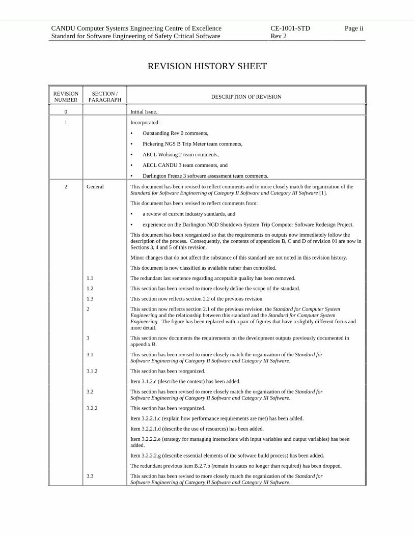
2 General This document has been revised to reflect comments and to more closely match the organization of theStandard for Software Engineering of Category II Software and Category III Software [1].
This document has been revised to reflect comments from:
• a review of current industry standards, and
• experience on the Darlington NGD Shutdown System Trip Computer Software Redesign Project.
This document has been reorganized so that the requirements on outputs now immediately follow thedescription of the process. Consequently, the contents of appendices B, C and D of revision 01 are now inSections 3, 4 and 5 of this revision.
Minor changes that do not affect the substance of this standard are not noted in this revision history.
This document is now classified as available rather than controlled.
1.1 The redundant last sentence regarding acceptable quality has been removed.
1.2 This section has been revised to more closely define the scope of the standard.
1.3 This section now reflects section 2.2 of the previous revision.
2 This section now reflects section 2.1 of the previous revision, the Standard for Computer SystemEngineering and the relationship between this standard and the Standard for Computer SystemEngineering. The figure has been replaced with a pair of figures that have a slightly different focus andmore detail.
3 This section now documents the requirements on the development outputs previously documented inappendix B.
3.1 This section has been revised to more closely match the organization of the Standard forSoftware Engineering of Category II Software and Category III Software.
3.1.2 This section has been reorganized.
Item 3.1.2.c (describe the context) has been added.
3.2 This section has been revised to more closely match the organization of the Standard forSoftware Engineering of Category II Software and Category III Software.
3.2.2 This section has been reorganized.
Item 3.2.2.1.c (explain how performance requirements are met) has been added.
Item 3.2.2.1.d (describe the use of resources) has been added.
Item 3.2.2.2.e (strategy for managing interactions with input variables and output variables) has beenadded.
Item 3.2.2.2.g (describe essential elements of the software build process) has been added.
The redundant previous item B.2.7.b (remain in states no longer than required) has been dropped.
3.3 This section has been revised to more closely match the organization of the Standard forSoftware Engineering of Category II Software and Category III Software.
Approved for Issue - VERIFY STATUS PRIOR TO USE
CANDU Computer Systems Engineering Centre of ExcellenceStandard for Software Engineering of Safety Critical Software
CE-1001-STDRev 2
Page iii
REVISIONNUMBER
SECTION /PARAGRAPH
DESCRIPTION OF REVISION
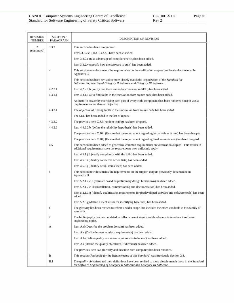
2(continued)
3.3.2 This section has been reorganized.
Items 3.3.2.c.1 and 3.3.2.c.3 have been clarified.
Item 3.3.2.e (take advantage of compiler checks) has been added.
Item 3.3.2.v (specify how the software is built) has been added.
4 This section now documents the requirements on the verification outputs previously documented inAppendix C.
This section has been revised to more closely match the organization of the Standard forSoftware Engineering of Category II Software and Category III Software.
4.2.2.1 Item 4.2.2.1.b (verify that there are no functions not in SDD) has been added.
4.3.1.1 Item 4.3.1.1.a (to find faults in the translation from source code) has been added.
An item (to ensure by exercising each part of every code component) has been removed since it was arequirement rather than an objective.
4.3.2.1 The objective of finding faults in the translation from source code has been added.
The SDD has been added to the list of inputs.
4.3.2.2 The previous item C.8.i (random testing) has been dropped.
4.4.2.2 Item 4.4.2.2.b (define the reliability hypothesis) has been added.
The previous item C.10.i (Ensure that the requirement regarding initial values is met) has been dropped.
The previous item C.10.j (Ensure that the requirement regarding final values is met) has been dropped.
4.5 This section has been added to generalize common requirements on verification outputs. This results inadditional requirements since the requirements now uniformly apply.
Item 4.5.1.j.3 (verify compliance with the SPH) has been added.
Item 4.5.3.i (identify corrective action lists) has been added.
Item 4.5.3.j (identify actual items used) has been added.
5 This section now documents the requirements on the support outputs previously documented inAppendix D.
Item 5.2.1.2.c.1 (estimate based on preliminary design breakdown) has been added.
Item 5.2.1.2.c.10 (installation, commissioning and documentation) has been added.
Item 5.2.1.3.g (identify qualification requirements for predeveloped software and software tools) has beenadded.
Item 5.2.3.g (define a mechanism for identifying baselines) has been added.
6 The glossary has been revised to reflect a wider scope that includes the other standards in this family ofstandards.
7 The bibliography has been updated to reflect current significant developments in relevant softwareengineering topics.
A Item A.d (Describe the problem domain) has been added.
Item A.e (Define human interface requirements) has been added.
Item A.h (Define quality assurance requirements to be met) has been added.
Item A.i (Define the quality objectives, if different) has been added.
The previous item A.d (identify and describe each computer) has been removed.
B This section (Rationale for the Requirements of this Standard) was previously Section 2.4.
B.1 The quality objectives and their definitions have been revised to more closely match those in the Standardfor Software Engineering of Category II Software and Category III Software.
Approved for Issue - VERIFY STATUS PRIOR TO USE
CANDU Computer Systems Engineering Centre of ExcellenceStandard for Software Engineering of Safety Critical Software
CE-1001-STDRev 2
Page iv
REVISIONNUMBER
SECTION /PARAGRAPH
DESCRIPTION OF REVISION
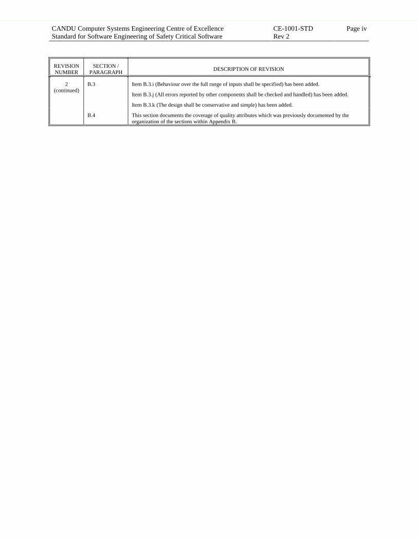
2(continued)
B.3 Item B.3.i (Behaviour over the full range of inputs shall be specified) has been added.
Item B.3.j (All errors reported by other components shall be checked and handled) has been added.
Item B.3.k (The design shall be conservative and simple) has been added.
B.4 This section documents the coverage of quality attributes which was previously documented by theorganization of the sections within Appendix B.
Approved for Issue - VERIFY STATUS PRIOR TO USE
CANDU Computer Systems Engineering Centre of ExcellenceStandard for Software Engineering of Safety Critical Software
CE-1001-STDRev 2
Page v
FOREWORD
This standard has been jointly prepared by Ontario Power Generation, Nuclear andAtomic Energy of Canada Limited to specify the requirements for the engineering of safetycritical software used in real-time protective, control and monitoring systems in CANDU®
nuclear generating stations.
This standard is part of a family of standards defining the engineering requirements for differentclasses and categories of real-time software, which are distinguished by criticality of application,complexity of system and source of supply.
This standard differs from the Standard for Software Engineering of Category II Software andCategory III Software by requiring systematic (mathematical) verification, hazards analysis andreliability qualification and by imposing more rigorous requirements on the other processesidentified.
This standard is not intended to specified all quality assurance program requirements, rather itprovides specific requirements for software engineering. The quality assurance programrequirements not addressed in this standard are addressed in the AECL quality assuranceprogram and the Ontario Power Generation, Nuclear set of Governing Documents.
Although the standard is meant to be methodology independent, it is written assuming the use ofprocedural languages. The principles apply equally well to other methodologies, such asFunctional Graphical Languages, but in such cases, some specific details require tailoring.
A number of national and international standards have been consulted in the preparation of thissoftware standard. The largest contribution has come from the two standards listed below. Thisstandard also owes much of its content to the experience gained in developing, licensing, andmaintaining software for the Darlington Nuclear Generating Station Shutdown System TripComputers, as well as other safety critical software.
• IEC 60880, “Software for Computers in the Safety Systems of Nuclear Power Stations”
• CAN/CSA-Q396.1.1-89, “Quality Assurance Program for the Development of SoftwareUsed in Critical Applications”
Other standards, guides and papers used are listed in the bibliography. Documents directlyreferred to are listed in the references section.
Italicized words are used in this standard to denote words defined in the Glossary (Section 6). Ingeneral, such a word is italicized the first time that it appears in a section of this standard.
Approved for Issue - VERIFY STATUS PRIOR TO USE

CANDU Computer Systems Engineering Centre of ExcellenceStandard for Software Engineering of Safety Critical Software
CE-1001-STDRev 2
Page vi
Approved for Issue - VERIFY STATUS PRIOR TO USE
CANDU Computer Systems Engineering Centre of ExcellenceStandard for Software Engineering of Safety Critical Software
CE-1001-STDRev 2
Page vii
TABLE OF CONTENTS
1 INTRODUCTION ................................................................................................................................11.1 Purpose ........................................................................................................................................................... 11.2 Scope .............................................................................................................................................................. 21.3 Structure of this Document ............................................................................................................................. 2
2 SOFTWARE ENGINEERING PROCESS ........................................................................................3
3 DEVELOPMENT PROCESSES.........................................................................................................73.1 Requirements Definition................................................................................................................................. 73.2 Design............................................................................................................................................................. 93.3 Code Implementation.................................................................................................................................... 12
4 VERIFICATION AND VALIDATION PROCESSES....................................................................154.1 Review.......................................................................................................................................................... 15
4.1.1 Requirements Review ......................................................................................................................... 154.1.2 Design Review .................................................................................................................................... 164.1.3 Code Review ....................................................................................................................................... 17
4.2 Systematic Verification................................................................................................................................. 174.2.1 Systematic Design Verification........................................................................................................... 174.2.2 Systematic Code Verification.............................................................................................................. 18
4.3 Testing .......................................................................................................................................................... 194.3.1 Unit Testing......................................................................................................................................... 194.3.2 Integration Testing .............................................................................................................................. 214.3.3 Validation Testing............................................................................................................................... 22
4.4 Other ............................................................................................................................................................. 234.4.1 Hazards Analysis................................................................................................................................. 234.4.2 Reliability Qualification...................................................................................................................... 24
4.5 Common Verification and Validation Output Requirements........................................................................ 254.5.1 Test Procedures ................................................................................................................................... 254.5.2 Test Reports ........................................................................................................................................ 264.5.3 Reports ................................................................................................................................................ 27
5 SUPPORT PROCESSES ...................................................................................................................285.1 Objectives ..................................................................................................................................................... 28
5.1.1 Planning .............................................................................................................................................. 285.1.2 Configuration Management................................................................................................................. 295.1.3 Training............................................................................................................................................... 29
5.2 Requirements on the SDP............................................................................................................................. 305.2.1 Project Plan ......................................................................................................................................... 305.2.2 Documentation Plan ............................................................................................................................ 335.2.3 Configuration Management Plan......................................................................................................... 345.2.4 Training Plan....................................................................................................................................... 35
5.3 Requirements on the SPH............................................................................................................................. 355.3.1 Process Standards and Procedures ...................................................................................................... 355.3.2 Documentation Standards and Procedures .......................................................................................... 365.3.3 Configuration Management Standards and Procedures....................................................................... 375.3.4 Training Standards and Procedures..................................................................................................... 38
6 GLOSSARY ........................................................................................................................................39
Approved for Issue - VERIFY STATUS PRIOR TO USE

CANDU Computer Systems Engineering Centre of ExcellenceStandard for Software Engineering of Safety Critical Software
CE-1001-STDRev 2
Page viii
7 REFERENCES ...................................................................................................................................51
8 BIBLIOGRAPHY...............................................................................................................................52
APPENDIX A PREREQUISITES FOR THE SOFTWARE ENGINEERING PROCESS...............57
APPENDIX B RATIONALE FOR THE REQUIREMENTS OF THIS STANDARD......................59B.1 Quality Objectives ........................................................................................................................................ 60B.2 Quality Attributes ......................................................................................................................................... 61B.3 Software Engineering Principles................................................................................................................... 62B.4 Coverage of the Quality Attributes ............................................................................................................... 64
B.4.1 Coverage of the Quality Attributes by the SRS................................................................................... 64B.4.2 Coverage of the Quality Attributes by the SDD.................................................................................. 65B.4.3 Coverage of the Quality Attributes by the Code ................................................................................. 66
INDEX........................................................................................................................................................67
LIST OF FIGURES AND TABLES
Figure 2-1 - Software Engineering Process: Development, Review and Testing................................................................4Figure 2-2 - Software Engineering Process: Systematic Verification, Hazards Analysis and Reliability Qualification....5Table 2-1 - Software Engineering Processes and Outputs....................................................................................................6Table 5.2.1.3 - Independence Requirements.......................................................................................................................32
Approved for Issue - VERIFY STATUS PRIOR TO USE
CANDU Computer Systems Engineering Centre of ExcellenceStandard for Software Engineering of Safety Critical Software
CE-1001-STDRev 2
Page 1
1 INTRODUCTION
1.1 Purpose
This standard applies to the software engineering of safety critical software used in real-timeprotective, control and monitoring systems. Software engineering includes requirementsdefinition, design, code implementation, review, systematic verification, testing,hazards analysis, reliability qualification, planning, configuration management and trainingprocesses.
This standard applies to safety critical software (also known as category I software) which is partof a special safety system and which is directly required for the special safety system to meet itsminimum allowable performance requirements as defined for the specific project. In a CANDUnuclear generating station, the four special safety systems are the two shutdown systems, theemergency core cooling system and the containment system.
This standard defines:
• A minimum set of software engineering processes to be followed in creating and revising thesoftware,
• The minimum set of outputs to be produced by the processes, and
• Requirements for the content of the outputs.
The requirements in this standard are not intended to unnecessarily constrain the methodologiesand work practices used for producing the outputs. Thus, requirements are imposed on theoutputs produced, not on the methodology used to create the outputs. As well, flexibility in theprocesses followed and documents produced is allowed, within the constraint of meeting allrequirements presented in this standard. For example, two documents may be combined into asingle document, as long as the cumulative requirements presented are met by that newdocument. Document names may be changed to suit the project conventions. Levels of testingmay be combined or split, if the project organization warrants it, providing that the coverage andother requirements of this standard are met.
This standard requires that the software engineering project using it adopt and/or define anddocument the standards, procedures, methodologies, and guidelines for the work practices thatwill be employed (including this standard). These standards, procedures, methodologies, andguidelines shall be followed throughout the system life to provide confidence that the softwarewithin the system is of acceptable quality from inception until retirement.
Approved for Issue - VERIFY STATUS PRIOR TO USE

CANDU Computer Systems Engineering Centre of ExcellenceStandard for Software Engineering of Safety Critical Software
CE-1001-STDRev 2
Page 2
1.2 Scope
This standard applies to software engineering of safety critical software used in real-timeprotective, control and monitoring systems used in CANDU® nuclear generating stations.
The standard is not intended to apply directly to systems programmed in non-procedurallanguages such as function-block languages, although a tailored version of this standard could beused for such applications.
This standard does not explicitly impose requirements on the acquisition or qualification ofpredeveloped software. However, there may be requirements imposed on predeveloped softwarecoming from the engineering of software according to this standard.
This standard is not intended to apply directly to software not originally developed to thisstandard. This standard is not intended to apply directly to the modification of existing softwarenot developed to this standard.
1.3 Structure of this Document
Section 2 describes the software engineering process.
Section 3 describes the processes of, inputs to, and outputs from the development process.Section 4 describes the processes of, inputs to, and outputs from the verification and validationprocess. Section 5 describes the processes of, inputs to, and outputs from the support processes.These sections also list the requirements to be met by the outputs of these processes.
The glossary (Section 6) contains terminology necessary to understand this document.
Appendix A specifies minimum requirements for the Design Input Documentation.
Appendix B documents the rationale for the requirements specified in this standard.
Throughout this standard,
• Terms shown in Italics are defined in the glossary (Section 6),
• Numbers within square brackets “[]” indicate references listed in Section 7 and
• Section numbers, where referred to, pertain to this standard.
Approved for Issue - VERIFY STATUS PRIOR TO USE

CANDU Computer Systems Engineering Centre of ExcellenceStandard for Software Engineering of Safety Critical Software
CE-1001-STDRev 2
Page 3
2 SOFTWARE ENGINEERING PROCESS
This standard defines a minimum set of processes that must be part of the software engineeringeffort for category I software. These processes are development, verification, validation orsupport processes. For each process defined, this standard identifies the outputs that must beproduced and the requirements that those outputs must satisfy.
The software engineering process is a distinct set of activities that forms an integral part of theengineering of a computer system such as described in the Standard for Computer SystemEngineering [2]. The prerequisite information for the software engineering process iscollectively referred to as the Design Input Documentation (DID) and is described inAppendix A. If the Standard for Computer System Engineering has been applied, thisinformation will be contained as part of its development outputs.
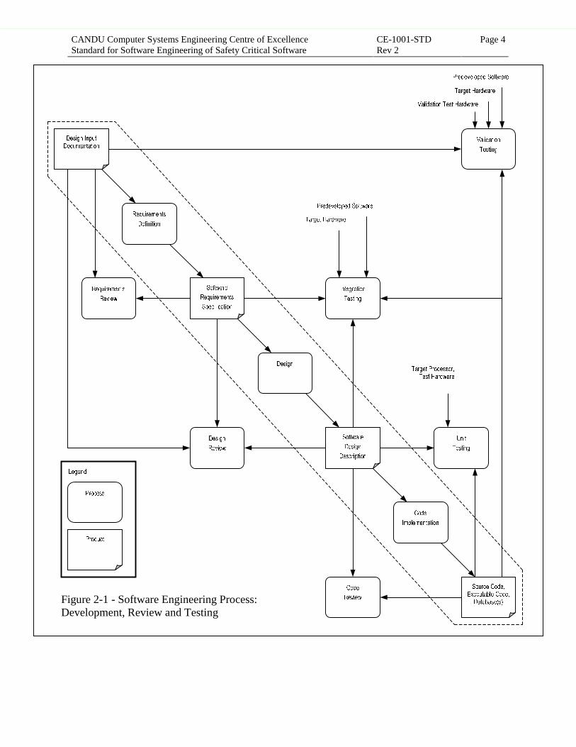
The intent of the software engineering process is to achieve the required outputs through acomprehensive sequence of development, verification and validation steps. These steps areshown in Figures 2-1 and 2-2. Development involves requirements definition followed bydesign followed by code implementation. This is shown in the main diagonal in the two figures.Verification and validation of the development process outputs are performed after the outputsare produced. Figure 2-1 shows development with the review and testing portions of verificationand validation. Figure 2-2 shows development with the systematic verification, hazardsanalysis, and reliability qualification portions of verification. For clarity, these figures do notshow the verification or validation products. The outputs of all processes are listed in Table 2-1.
In practice, this sequential model is not followed exactly since there is feedback to precedingprocesses and iterations are required. However, when iteration occurs, it must be performed inconformance with the established procedures. Any release of the software intended for use inactual operation, including maintenance releases, must satisfy all requirements as if thesequential model had been followed.
The software engineering process for a specific project is completely defined in the SoftwareDevelopment Plan (SDP) and the Standards and Procedures Handbook (SPH), which areproduced to meet the requirements of this standard. The requirements specified in the SDP andSPH shall be followed by the project.
Approved for Issue - VERIFY STATUS PRIOR TO USE
CANDU Computer Systems Engineering Centre of ExcellenceStandard for Software Engineering of Safety Critical Software
CE-1001-STDRev 2
Page 4
5HTXLUHPHQWV
'HILQLWLRQ
'HVLJQ�,QSXW'RFXPHQWDWLRQ
6RXUFH�&RGH�([HFXWDEOH�&RGH�
'DWDEDVH�V�
6RIWZDUH
'HVLJQ
'HVFULSWLRQ
6RIWZDUH
5HTXLUHPHQWV
6SHFLILFDWLRQ
5HTXLUHPHQWV
5HYLHZ
'HVLJQ
5HYLHZ
'HVLJQ
&RGH
,PSOHPHQWDWLRQ
&RGH
5HYLHZ
8QLW
7HVWLQJ
,QWHJUDWLRQ
7HVWLQJ
Figure 2-1 - Software Engineering Process:Development, Review and Testing
3UHGHYHORSHG�6RIWZDUH
7DUJHW�+DUGZDUH
7DUJHW�3URFHVVRU�7HVW�+DUGZDUH
9DOLGDWLRQ
7HVWLQJ
/HJHQG�
3URFHVV
3URGXFW
3UHGHYHORSHG�6RIWZDUH
7DUJHW�+DUGZDUH
9DOLGDWLRQ�7HVW�+DUGZDUH
Approved for Issue - VERIFY STATUS PRIOR TO USE

CANDU Computer Systems Engineering Centre of ExcellenceStandard for Software Engineering of Safety Critical Software
CE-1001-STDRev 2
Page 5
5HTXLUHPHQWV
'HILQLWLRQ
'HVLJQ�,QSXW'RFXPHQWDWLRQ
6RXUFH�&RGH�([HFXWDEOH�&RGH�
'DWDEDVH�V�
6RIWZDUH
'HVLJQ
'HVFULSWLRQ
6RIWZDUH
5HTXLUHPHQWV
6SHFLILFDWLRQ
'HVLJQ
&RGH
,PSOHPHQWDWLRQ
Figure 2-2 - Software Engineering Process:Development, Systematic Verification,Hazards Analysis, Reliability Qualification
5HOLDELOLW\4XDOLILFDWLRQ
+D]DUGV$QDO\VLV
6\VWHPDWLF&RGH
9HULILFDWLRQ
6\VWHPDWLF'HVLJQ
9HULILFDWLRQ
/HJHQG�
3URFHVV
3URGXFW
3UHGHYHORSHG�6RIWZDUH
7DUJHW�+DUGZDUH
3URFHVV�6LPXODWRU
+D]DUGV$QDO\VLV
+D]DUGV$QDO\VLV
+D]DUGV$QDO\VLV
Approved for Issue - VERIFY STATUS PRIOR TO USE
CANDU Computer Systems Engineering Centre of ExcellenceStandard for Software Engineering of Safety Critical Software
CE-1001-STDRev 2
Page 6
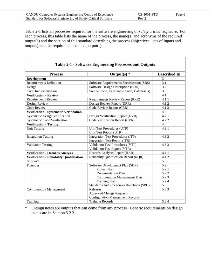
Table 2-1 lists all processes required for the software engineering of safety critical software. Foreach process, this table lists the name of the process, the name(s) and acronyms of the requiredoutput(s) and the section of this standard describing the process (objectives, lists of inputs andoutputs) and the requirements on the output(s).
Table 2-1 - Software Engineering Processes and Outputs
Process Output(s) * Described InDevelopment 3Requirements Definition Software Requirements Specification (SRS) 3.1Design Software Design Description (SDD) 3.2Code Implementation Source Code, Executable Code, Database(s) 3.3Verification - Review 4.1Requirements Review Requirements Review Report (RRR) 4.1.1Design Review Design Review Report (DRR) 4.1.2Code Review Code Review Report (CRR) 4.1.3Verification - Systematic Verification 4.2Systematic Design Verification Design Verification Report (DVR) 4.2.1Systematic Code Verification Code Verification Report (CVR) 4.2.2Verification - Testing 4.3Unit Testing Unit Test Procedures (UTP)
Unit Test Report (UTR)4.3.1
Integration Testing Integration Test Procedures (ITP)Integration Test Report (ITR)
4.3.2
Validation Testing Validation Test Procedures (VTP)Validation Test Report (VTR)
4.3.3
Verification - Hazards Analysis Hazards Analysis Report (HAR) 4.4.1Verification - Reliability Qualification Reliability Qualification Report (RQR) 4.4.2Support 5Planning Software Development Plan (SDP)
Project PlanDocumentation PlanConfiguration Management PlanTraining Plan
Standards and Procedures Handbook (SPH)
5.25.2.15.2.25.2.35.2.45.3
Configuration Management ReleasesApproved Change RequestsConfiguration Management Records
5.3.3
Training Training Records 5.3.4
* Design notes are outputs that can come from any process. Generic requirements on designnotes are in Section 5.2.2.
Approved for Issue - VERIFY STATUS PRIOR TO USE
CANDU Computer Systems Engineering Centre of ExcellenceStandard for Software Engineering of Safety Critical Software
CE-1001-STDRev 2
Page 7
3 DEVELOPMENT PROCESSES
This section describes the objectives, inputs and outputs of the development processes. Theseprocesses are:
• Requirements Definition,
• Design, and
• Code Implementation.
3.1 Requirements Definition
3.1.1 Objectives
The objectives of the Requirements Definition process are:
(a) To analyze and document the requirements for the software.
(b) To identify and document any implementation constraints on the software.
The inputs to this process are the DID and SPH. The output of this process is the SoftwareRequirements Specification (SRS).
3.1.2 Requirements on the SRS
The Software Requirements Specification (SRS) contains all requirements from the DID whichare relevant to the software as well as all other software specific requirements which arise due tothe environment in which the software will operate. The SRS presents an external view of thesoftware by providing a “black box” description of its behaviour.
Internal design details are not incorporated into the SRS so that software design decisions are notartificially constrained. The SRS does, however, document all necessary software designconstraints and these may limit the solutions from which the developer has to choose.
The SRS shall:
(a) Specify all requirements derived from the DID which are relevant to the software. Thisincludes all functional, performance, safety, reliability, security, operability, andmaintainability requirements.
(b) Specify all requirements derived from sources other than the DID. Justification shall beprovided for each of these requirements, along with identification of the source.
(c) Describe the context of the software subsystem.
Approved for Issue - VERIFY STATUS PRIOR TO USE

CANDU Computer Systems Engineering Centre of ExcellenceStandard for Software Engineering of Safety Critical Software
CE-1001-STDRev 2
Page 8
(d) Identify those properties of the physical environment (that is, temperatures, pressures,display readings, etc.) that the software must monitor and/or control and represent themwith mathematical variables (monitored variables and controlled variables).
(e) Specify the characteristics of variables the software has access to (input variables andoutput variables), addressing such issues as types, formats, units, and valid ranges.
(f) Specify the relationship between the monitored variables and input variables and betweenthe output variables and controlled variables. This may be achieved by referencingappropriate hardware and/or predeveloped software documents.
(g) Define, with the use of mathematical functions, the required behaviour of thecontrolled variables in terms of the monitored variables. The entire domain of themonitored variables shall be covered by these definitions. The mathematical functions shalluse a notation that has consistent, unambiguous, precisely defined syntax and semantics.
(h) Specify the response to all expected types of errors and failure modes identified by thehazards analysis of the system described in the DID. Indicate all cases for which errorrecovery must be attempted or for which fail-safe action must be taken.
(i) Specify requirements for fault tolerance and graceful degradation.
(j) Specify the timing tolerances and the accuracy requirements as the allowable deviationfrom the required behaviour of the controlled variables.
(k) Identify all those requirements for which future changes are anticipated. This will providea basis for the use of information hiding concepts in the design.
(l) Identify any software implementation design constraints. This might include the processorson which the software is required to execute, and the predeveloped software required to beused.
(m) Present requirements and design constraints only. It shall limit the range of valid solutions,but shall not specify a particular design.
(n) Specify no requirements that are in conflict with each other.
(o) Specify each unique requirement once to prevent inconsistent updates.
(p) Identify each requirement uniquely so that it can be readily referenced by the SDD.
(q) Reference design notes that document design decisions relevant to the softwarerequirements.
(r) Demonstrate explicitly the mapping and complete coverage of all relevant requirements anddesign constraints in the DID by such means as a coverage matrix or cross-reference.
(s) Conform to the applicable standards and procedures in the SPH.
Approved for Issue - VERIFY STATUS PRIOR TO USE

CANDU Computer Systems Engineering Centre of ExcellenceStandard for Software Engineering of Safety Critical Software
CE-1001-STDRev 2
Page 9
(t) Use consistent terminology and definitions throughout the document.
(u) Enable its intended audience to effectively determine the role each SRS component plays inthe subsystem.
3.2 Design
3.2.1 Objectives
The objectives of the Design process are:
(a) To produce a software architecture and detailed design that satisfies the requirements in theSRS.
(b) To identify self-checks not derived from the SRS that enhance the robustness of the designto hardware failures or other system level hazards.
The inputs to this process are the SRS and SPH. The output is the Software Design Description(SDD).
3.2.2 Requirements on the SDD
The Software Design Description (SDD) is a representation of the software design.
3.2.2.1 Architecture
The SDD shall:
(a) Describe a design that meets all functional, performance, safety, reliability, security,operability, and maintainability requirements of the subsystem and all design constraints asdescribed in the SRS.
(b) Define a design that meets the requirements of the SRS to a level of detail that requires nofurther refinement of the module structure, module program functions, module interfaces,data structures, or databases in the code.
(c) Explain how performance requirements are met by the design, using worst case analysis.
(d) Describe the use of resources (for example, memory, processing time) by the design.
(e) Explain how the fault tolerance and graceful degradation requirements are met by thedesign.
(f) Define a method of scheduling computer resources that is primarily deterministic andpredictable rather than dynamic.
Approved for Issue - VERIFY STATUS PRIOR TO USE
CANDU Computer Systems Engineering Centre of ExcellenceStandard for Software Engineering of Safety Critical Software
CE-1001-STDRev 2
Page 10
(g) Minimize the use of interrupts and event driven software.
(h) Provide justification for all uses of interrupts and event driven software.
(i) Use a logical control structure. Control must pass from the highest to successively moredetailed levels. Control must always be returned to the calling program, with the exceptionof error/exception handlers.
(j) Describe a design using information hiding concepts, as follows:
1. Organize modules so that anticipated changes in the requirements can be implementedby only requiring changes to one or a small number of modules.
2. Design those functions and data structures likely to change with interfaces to beinsensitive to changes in individual functions.
3. Describe a design which partitions data structure access, database access and I/Oaccess from the application software by the use of access programs (globally accessibledata must not be used).
4. Partition functionality into programs to maximize the internal cohesion of programsand to minimize program coupling.
(k) Describe a design in which each program has a single purpose.
(l) Use specific criteria to limit program size.
3.2.2.2 Detailed Design
The SDD shall:
(a) Provide the following information for each module:
1. A unique identifying name.
2. The purpose of the module.
3. The data structure(s) maintained by the module.
4. The list of programs contained in the module.
(b) Provide the following information for each program:
1. Unique identifying name.
2. Program type (e.g., main program, subroutine, function, macro, interrupt handler).
3. The purpose of the program (what requirement it satisfies).
4. The behaviour of each program covering the entire domain of each program input.
5. The subordinates which compose the program (to identify hierarchical structure toassist in tracing requirements).
Approved for Issue - VERIFY STATUS PRIOR TO USE
CANDU Computer Systems Engineering Centre of ExcellenceStandard for Software Engineering of Safety Critical Software
CE-1001-STDRev 2
Page 11
6 Program dependencies (necessary relationships with other programs, such as:interactions, data flow, timing, order of execution, data sharing, etc.).
7. Program interfaces (method of invocation or interruption, communication viaparameters, database access, message passing, protocols, data formats, ranges ofvalidity).
8. Required resources (elements external to the design; for example, devices, softwareservices, libraries, operating system services, processing resource requirements).
9. Program processing details, if necessary, to ensure that a particular algorithm is used(refinement of function, algorithm, contingency responses to error cases, timing,sequence of events, priorities, processing steps).
10. Program local data definitions (data type, initial value, use, valid range).
11. The programming language (or subset of the programming language) to be used.
(c) Identify processing steps within programs so that they can be uniquely referenced by thesource code.
(d) Include or reference design notes that document design decisions relevant to the softwaredesign.
(e) Describe the strategy for managing interactions (e.g., serial input queues, analog inputdelays) between the software and the input variables and output variables.
(f) Define the types and handling of errors that are not specified in the SRS.
(g) Describe all elements of the software build process essential to the design.
(h) Define plausibility checking on the execution of programs to uncover errors associated withthe frequency and/or order of program execution and, where applicable, the permissivenessof program execution.
(i) Describe the behaviour of each program using a notation that has precisely defined syntaxand semantics so that the SDD can be systematically verified against the SRS and so thatthe code can be systematically verified against the SDD.
3.2.2.3 General
The SDD shall:
(a) Factor in relevant experience from the previous systems that are identified in the SDP.
(b) Identify and provide rationale for all behaviour specified in the SDD that is outside thescope of the SRS.
(c) Identify and provide rationale for any requirement that cannot be met.
Approved for Issue - VERIFY STATUS PRIOR TO USE

CANDU Computer Systems Engineering Centre of ExcellenceStandard for Software Engineering of Safety Critical Software
CE-1001-STDRev 2
Page 12
(d) Demonstrate the mapping and complete coverage of all requirements and design constraintsin the SRS by means such as a coverage matrix or a cross reference.
(e) Conform to the applicable standards, procedures and guidelines in the SPH.
(f) Use consistent terminology and definitions through out the document.
(g) Avoid unnecessarily complex designs and design representations.
(h) Enable its intended audience to effectively determine the role each component plays in theoverall design.
(i) Specify only programming languages (or subsets of each programming language) that havea defined syntax and semantics so that the results of any program constructs areunambiguous.
3.3 Code Implementation
3.3.1 Objectives
The objectives of the Code Implementation process are:
(a) To translate the SDD into source code.
(b) To translate the source code into executable code.
(c) To integrate the executable code.
(d) To debug the executable code.
(e) To create all required databases complete with appropriate initial data.
The inputs to this process are the SDD and SPH. The outputs are the source code, executablecode, databases and build by-products such as memory maps and build logs.
3.3.2 Requirements on the Code
The source code is a complete and accurate translation of the design described in the SDD.
The source code shall:
(a) Precisely implement the design as described in the SDD.
(b) Compile without error.
Approved for Issue - VERIFY STATUS PRIOR TO USE

CANDU Computer Systems Engineering Centre of ExcellenceStandard for Software Engineering of Safety Critical Software
CE-1001-STDRev 2
Page 13
(c) Use structured programming. Specifically, the code shall:
1. Not contain variable performance constructs (e.g., recursion).
2. Not contain any self-modifying code.
3. Not contain any potential infinite loops (with the possible exceptions of the mainlineand fatal error handlers).
4. Not contain programs with multiple entry points or multiple exit points (with theexception of fatal error handling).
5. Not contain loops with multiple entrances.
6. Be written so that each function of the program is a recognizable block of code.
(d) Defend against detectable run-time errors. These errors include out-of-range array indexvalues, division by zero, out-of-range variables, and stack overflow.
(e) Take advantage of compiler-implemented type checking where this is feasible.
(f) Contain or reference a revision history of all code modifications and the reason for them.
(g) Have consistent and useful layout and format. Specifically, the code shall:
1. Use consistent indentation to show nesting of structures.
2. Use adequate white space to make structures stand out clearly.
3. Use comment blocks to highlight the overall flow of program logic.
(h) Have useful and clear comments using English language phrases. The comments shall:
1. Accurately describe the functionality of the code in terms of the parameters beingmonitored and/or controlled; or alternatively, provide precise cross-reference to theSDD where the functionality is specified,
2. Accurately describe the function of complex or non-obvious algorithms,
3. Not just mimic the code, and
4. Not make assumptions on the functionality of other modules such that the degree ofinformation hiding is reduced.
(i) Use consistently descriptive predefined naming conventions. The conventions mustdescribe the criteria they attempt to meet and the rationale for these criteria.
(j) Conform to the applicable standards, procedures and guidelines in the SPH.
(k) Avoid implementation practices and techniques that are more difficult to verify thannecessary.
(l) Not rely on any defaults provided by the programming language used, unless they are partof the standard language definition.
Approved for Issue - VERIFY STATUS PRIOR TO USE

CANDU Computer Systems Engineering Centre of ExcellenceStandard for Software Engineering of Safety Critical Software
CE-1001-STDRev 2
Page 14
(m) Ensure that the accuracy requirements of all variables (as described in the SDD) are met bythe implemented data types and algorithms.
(n) Define all required databases complete with appropriate initial data.
(o) Have data declarations that are consistent with their use.
(p) Not contain any unreferenced or undefined symbols.
(q) Refer to constants symbolically to facilitate change.
(r) Include cross-references or data dictionaries showing variable and constant access byprogram.
(s) Provide a cross-reference framework through which the code can be easily traced to theSDD.
(t) Reference the design notes that document design decisions relevant to the codeimplementation.
(u) Be written following guidelines that promote static logic. Examples of this include the useof constant maximum ranges on loops and the use of constants in branch tables.
(v) Specify how the software is built. This shall include all script files that build the software.
Approved for Issue - VERIFY STATUS PRIOR TO USE

CANDU Computer Systems Engineering Centre of ExcellenceStandard for Software Engineering of Safety Critical Software
CE-1001-STDRev 2
Page 15
4 VERIFICATION AND VALIDATION PROCESSES
This section describes the objectives, inputs and outputs of the verification and validationprocesses. These processes are:
• Review,
• Systematic Verification,
• Testing,
• Hazards Analysis, and
• Reliability Qualification.
4.1 Review
This section describes the objectives, inputs and outputs of the review processes. Theseprocesses are:
• Requirements Review,
• Design Review, and
• Code Review.
4.1.1 Requirements Review
4.1.1.1 Objectives
The objectives of the Requirements Review process are:
(a) To identify ambiguities and incompleteness in the requirements specified in the DID.
(b) To verify that the SRS meets the requirements of the DID.
(c) To verify the justification for including any requirements and design constraints in the SRSwhich were not derived from the DID.
(d) To verify that the SRS meets the requirements in the SPH.
The inputs to this process are the DID, SRS, and SPH. The output is the Requirements ReviewReport (RRR).
Approved for Issue - VERIFY STATUS PRIOR TO USE

CANDU Computer Systems Engineering Centre of ExcellenceStandard for Software Engineering of Safety Critical Software
CE-1001-STDRev 2
Page 16
4.1.1.2 Requirements on the RRR
The Requirements Review Report (RRR) shall:
(a) Provide evidence that the review has covered all requirements and design constraints in theDID and SRS.
(b) Provide evidence that the review has covered all requirements and design constraintsappearing in the SRS which are not derived from the DID.
(c) Provide evidence that the SRS has been reviewed against all applicable standards andprocedures in the SPH.
(d) Conform to the common requirements on reports (Section 4.5.3).
4.1.2 Design Review
4.1.2.1 Objectives
The objectives of the Design Review process are:
(a) To verify that the design decisions are consistent with good software engineering practice(i.e., that the defined software architecture is appropriate to meet all requirements andconstraints),
(b) To verify that the SDD meets the intent of the requirements specified in the SRS and DID,
(c) To check the justification for inclusion of any functionality outside the scope of therequirements to confirm that the resulting design is consistent with the intent of therequirements,
(d) To verify that the SDD meets the requirements in the SPH.
The inputs to this process are the DID, SRS, SDD, and SPH. The output is the Design ReviewReport (DRR).
4.1.2.2 Requirements on the DRR
The Design Review Report (DRR) shall:
(a) Provide evidence that the review has covered all sections in the SDD, including allmodules, programs, data structures, and databases.
(b) Provide evidence that the SDD has been reviewed against the all applicable standards,procedures and guidelines in the SPH.
(c) Conform to the common requirements on reports (Section 4.5.3).
Approved for Issue - VERIFY STATUS PRIOR TO USE
CANDU Computer Systems Engineering Centre of ExcellenceStandard for Software Engineering of Safety Critical Software
CE-1001-STDRev 2
Page 17
4.1.3 Code Review
4.1.3.1 Objectives
The objectives of the Code Review process are:
(a) To verify that the code implementation decisions are consistent with good softwareengineering practice based on expert opinion.
(b) To verify that the code meets the requirements in the SPH.
The inputs to this process are the SDD, source code, and SPH. The output is the Code ReviewReport (CRR).
4.1.3.2 Requirements on the CRR
The Code Review Report (CRR) shall:
(a) Provide evidence that the review has covered all programs, data structures, and databasesin the source code.
(b) Provide evidence that the source code has been reviewed against all applicable standards,procedures and guidelines in the SPH.
(c) Conform to the common requirements on reports (Section 4.5.3).
4.2 Systematic Verification
This section describes the objectives, inputs and outputs of the systematic verification processes.These processes are:
• Systematic Design Verification, and
• Systematic Code Verification.
4.2.1 Systematic Design Verification
4.2.1.1 Objectives
The objectives of the Systematic Design Verification process are:
(a) To verify, using mathematical verification techniques or rigorous arguments, that for everyoutput, the behaviour for that output as defined in the SDD is in compliance with therequirements for the behaviour imposed by the SRS.
Approved for Issue - VERIFY STATUS PRIOR TO USE

CANDU Computer Systems Engineering Centre of ExcellenceStandard for Software Engineering of Safety Critical Software
CE-1001-STDRev 2
Page 18
(b) To identify any functions outside the scope of the requirements specified in the SRS and tocheck that justification has been provided for their existence.
One of the side benefits of the Systematic Design Verification process is that it identifiesambiguities and incompleteness in the SRS.
The inputs to this process are the SRS, SDD and SPH. The output is the Design VerificationReport (DVR).
4.2.1.2 Requirements on the DVR
The Design Verification Report (DVR) shall:
(a) Provide evidence that the verification has covered all requirements in the SRS and allprograms, data structures and databases in the SDD.
(b) Provide evidence that the verification has covered justification for inclusion in the SDD ofany functionality outside the scope of the requirements in the SRS.
(c) Conform to the common requirements on reports (Section 4.5.3).
4.2.2 Systematic Code Verification
4.2.2.1 Objectives
The objectives of the Systematic Code Verification process are:
(a) To verify, using mathematical verification techniques or rigorous arguments, that thebehaviour of outputs with respect to inputs in the code is the same as that specified by theSDD for the entire domain of the inputs.
(b) To verify that there are no functions in the code which are not contained in the SDD.
One of the side benefits of Systematic Code Verification process is that it identifies ambiguitiesand incompleteness in the SDD.
The inputs to the process are the source code, SDD, and SPH. The output is the CodeVerification Report (CVR).
4.2.2.2 Requirements on the CVR
The Code Verification Report (CVR) shall:
(a) Provide evidence that the verification has covered all programs, data structures, anddatabases in the SDD and all of the source code.
Approved for Issue - VERIFY STATUS PRIOR TO USE

CANDU Computer Systems Engineering Centre of ExcellenceStandard for Software Engineering of Safety Critical Software
CE-1001-STDRev 2
Page 19
(b) Conform to the common requirements on reports (Section 4.5.3).
4.3 Testing
This section describes the objectives, inputs and outputs of the testing processes. Theseprocesses are:
• Unit Testing,
• Integration Testing, and
• Validation Testing.
The overall objectives of testing are to find faults in the software and problems in therequirements.
Each testing process includes:
• Preparing the Test Procedures,
• Verifying the Test Procedures,
• Carrying out the Test Procedures,
• Preparing the Test Report, and
• Verifying the Test Report.
4.3.1 Unit Testing
4.3.1.1 Objectives
The objectives of the Unit Testing process are:
(a) To find faults in the translation from source code to executable code.
(b) To test that the executable code of each program and module behaves as specified in theSDD.
(c) To test that the executable code of each program and module does not perform unintendedfunctions.
(d) To find faults in the program interfaces.
Approved for Issue - VERIFY STATUS PRIOR TO USE

CANDU Computer Systems Engineering Centre of ExcellenceStandard for Software Engineering of Safety Critical Software
CE-1001-STDRev 2
Page 20
The inputs to this process are the SDD, source code, executable code, databases, test hardware,and SPH. The outputs are the Unit Test Procedures (UTP), including test stubs and test drivers,and the Unit Test Report (UTR).
4.3.1.2 Requirements on the UTP
The Unit Test Procedures (UTP) shall:
(a) Define tests that are executed on the target processor but possibly using test drivers andstubs to simulate other parts of the system.
(b) Define a set of test cases, derived from the analysis of the SDD, to test that the executablecode for each program behaves as specified in the SDD. This set of test cases shall beconsidered sufficient when it includes:
1. All possible decision outcomes.
2. Tests on each boundary and values on each side of each boundary for each input. Thetest values shall be determined by using boundary value analysis and equivalencepartitioning.
3. Tests based on postulated coding implementation errors.
(c) Define a set of test cases, derived from the analysis of the code, to test that the executablecode for each program behaves as specified in the SDD. This set of test cases shall beconsidered sufficient when it causes:
1. Execution of every program statement.
2. Execution of all possible decision outcomes.
3. Execution of each loop with minimum, maximum, and at least one intermediatenumber of repetitions.
4. A read and write to every memory location used for variable data.
5. A read of every memory location used for constant data.
(d) Define a sufficient number of tests to cause each interface to be exercised.
(e) Require that the testing use the same compiler used to generate the final executable code.
(f) Conform to the common requirements on test procedures (Section 4.5.1).
4.3.1.3 Requirements on the UTR
The Unit Test Report (UTR) shall:
(a) Conform to the common requirements on test reports (Section 4.5.2).
Approved for Issue - VERIFY STATUS PRIOR TO USE

CANDU Computer Systems Engineering Centre of ExcellenceStandard for Software Engineering of Safety Critical Software
CE-1001-STDRev 2
Page 21
4.3.2 Integration Testing
4.3.2.1 Objectives
The objectives of the Integration Testing process are:
(a) To find faults in the translation from source code to integrated system.
(b) To test that the executable code meets the requirements specified in the SRS.
(c) To find faults in the interfaces between the software, target hardware and predevelopedsoftware.
(d) To find faults in handling stress conditions, timing, fail-safe features, error conditions, anderror recovery.
The inputs to this process are the SRS, SDD, source code, executable code, databases, targethardware, predeveloped software, and SPH. The outputs are the Integration Test Procedures(ITP), including test software, and the Integration Test Report (ITR).
4.3.2.2 Requirements on the ITP
The Integration Test Procedures (ITP) shall:
(a) Require all tests to be done with predeveloped software and target hardware.
(b) Define test cases to test each functional requirement in the SRS.
(c) Define test cases to test each performance requirement in the SRS.
(d) Identify all resources used by the software subsystem and define test cases to test thesoftware subsystem under conditions that attempt to overload the identified resources todetermine if the functional and performance requirements defined in the SRS are met.
(e) Define test cases to find faults in the interfaces between:
1. The modules of the custom developed software, and
2. The custom developed software and its environment (including hardware andpredeveloped software).
(f) Define test cases to find faults in each hardware configuration and with each operationaloption.
(g) Define test cases to find faults in the response to software, hardware, and data errors.
(h) Define test cases that attempt to subvert any existing safety or security mechanisms.
Approved for Issue - VERIFY STATUS PRIOR TO USE

CANDU Computer Systems Engineering Centre of ExcellenceStandard for Software Engineering of Safety Critical Software
CE-1001-STDRev 2
Page 22
(i) Conform to the common requirements on test procedures (Section 4.5.1).
4.3.2.3 Requirements on the ITR
The Integration Test Report (ITR) shall:
(a) Conform to the common requirements on test reports (Section 4.5.2).
4.3.3 Validation Testing
4.3.3.1 Objective
The objective of the Validation Testing process is:
(a) To test that the custom developed software, as built, correctly addresses the capabilitiesneeded by users.
The inputs to this process are the DID, ITP, custom developed software, target hardware,validation test hardware, predeveloped software, and SPH. Note that the definition of test cases,and the associated pass/fail criteria, are to be based on the involvement of the user or otherperson knowledgeable about the problem or objective to be addressed by the software, and theDID. The use of other documents is permitted, when necessary to set up the test scenarios, ifclearly noted in the Validation Test Procedures (VTP). The outputs are the VTP and theValidation Test Report (VTR).
4.3.3.2 Requirements on the VTP
The Validation Test Procedures (VTP) shall:
(a) Require all tests to be done on the entire software with the target hardware andpredeveloped software.
(b) Define test cases that exercise the capabilities needed by users.
(c) Define test cases, using dynamic simulation of input signals, to demonstrate the subsystemcapabilities under steady state conditions, changing input conditions, abnormal inputconditions, and accident conditions requiring software subsystem action as indicated in theDID. The test cases shall cover all modes of operation.
(d) Document coverage of all functional and performance requirements in the DID that areapplicable to the software subsystem.
(e) Conform to the common requirements on test procedures (Section 4.5.1).
Approved for Issue - VERIFY STATUS PRIOR TO USE
CANDU Computer Systems Engineering Centre of ExcellenceStandard for Software Engineering of Safety Critical Software
CE-1001-STDRev 2
Page 23
4.3.3.3 Requirements on the VTR
The Validation Test Report (VTR) shall:
(a) Conform to the common requirements on test reports (Section 4.5.2).
4.4 Other
4.4.1 Hazards Analysis
This section describes the objectives, inputs and outputs of the hazards analysis process.
4.4.1.1 Objectives
The objectives of the Hazards Analysis process are:
(a) To undertake a review of the software from the safety and reliability perspective (asorthogonal to the functional perspective) and thus identify any failure modes that can leadto an unsafe state and make recommendations for changes.
(b) To determine sequences of inputs which could lead to the software causing an unsafe stateand to make recommendations for changes.
(c) To verify that the software required to handle system failure modes does so effectively.
Hazards analyses are performed at several points in the software design process. The inputs tothe process are the DID, SRS, SDD, source code, databases, and software safety designprinciples contained in the SPH. The output is the Hazards Analysis Report (HAR).
4.4.1.2 Requirements on the HAR
The Hazards Analysis Report (HAR) shall:
(a) Identify software safety design principles that are proactively applied to mitigate potentialhazards.
(b) Identify the input conditions and subsystem failures that could lead to the software causingan unsafe state. For example:
1. RAM variables whose corruption could lead to an unsafe subsystem failure.
2. ROM constants whose corruption could lead to an unsafe subsystem failure.
3. Code sequences that could lead to an unsafe subsystem failure.
(c) Identify all self-checking software and its ability to eliminate the identified failure modes orreduce their likelihood of occurring.
Approved for Issue - VERIFY STATUS PRIOR TO USE

CANDU Computer Systems Engineering Centre of ExcellenceStandard for Software Engineering of Safety Critical Software
CE-1001-STDRev 2
Page 24
(d) Identify and recommend modifications to the software and the safety design principles thatwould eliminate the identified failure modes or reduce their likelihood of occurring.
(e) Conform to the common requirements on reports (Section 4.5.3).
4.4.2 Reliability Qualification
This section describes the objectives, inputs and outputs of the reliability qualification process.
4.4.2.1 Objectives
The objective of Reliability Qualification process is:
(a) To demonstrate that the reliability requirements are achieved for the executable code(integrated with the target hardware and any predeveloped software) with the degree ofconfidence necessary (as specified in the DID or SRS).
The inputs to Reliability Qualification are the DID, code, target hardware, and predevelopedsoftware. The SRS may also be used to supplement the DID if it does not provide sufficientlydetailed information. The outputs are the Reliability Qualification Procedure (RQP) and theReliability Qualification Report (RQR).
4.4.2.2 Requirements on the RQP
The Reliability Qualification Procedures (RQP) shall:
(a) Require all tests to be done with the target hardware and predeveloped software.
(b) Define the reliability hypothesis.
(c) Explicitly identify the basis for the reliability hypothesis.
(d) Define a sufficient number of tests representative of the software’s usage profile, to providestatistically valid evidence showing that the probability of failure of the software is smallenough that the computer system will meet its reliability requirements as described in theDID.
(e) Define each test in terms of:
1. The initial value of each input.
2. The final value of each input.
3. The length of time of the test or period.
4. The time-related function describing how each input will vary over the period of thetest.
Approved for Issue - VERIFY STATUS PRIOR TO USE

CANDU Computer Systems Engineering Centre of ExcellenceStandard for Software Engineering of Safety Critical Software
CE-1001-STDRev 2
Page 25
(f) Randomly select the initial input values from a distribution that is representative of thevalues seen when the system is not required to act.
(g) Randomly select the final input values from a distribution that is representative of thevalues seen when the system is required to act.
(h) For each input, randomly select the time-related function from a representative distributionthat represents intermediate values assumed by the input as it progresses from the initialvalue to the final value. The function will include the effects of instrument response times,signal noise, and any other characteristics that are known about the input.
(i) Randomly select the time period of the tests and ensure that all retained memory isinitialized prior to running each test, so that the effects of the retained memory of thesoftware do not invalidate the independence requirement between tests to ensure statisticalvalidity. Justification shall be provided for any exceptions made to this requirement (forexample, excessively long or infinite time periods not covered).
(j) Provide justification supporting the chosen distributions showing that they arerepresentative of the software’s usage profile.
(k) Identify all equipment (and its required calibration), tools, and support software required toproduce the input and expected result data for the test cases.
(l) Conform to the common requirements on test procedures (Section 4.5.1).
4.4.2.3 Requirements on the RQR
The Reliability Qualification Report (RQR) shall:
(a) Conform to the common requirements on test reports (Section 4.5.2).
4.5 Common Verification and Validation Output Requirements
This section defines the requirements common to all verification and validation outputs.Verification and validation outputs include review reports, systematic verification reports, testprocedures and test reports.
4.5.1 Test Procedures
All test procedures shall:
(a) Describe expected results of each test case from information provided in the inputdocument(s) so that a pass/fail determination can be made as to the outcome of the test.
(b) Define the acceptance criteria for comparing the expected behaviour and actual behaviour.
Approved for Issue - VERIFY STATUS PRIOR TO USE
CANDU Computer Systems Engineering Centre of ExcellenceStandard for Software Engineering of Safety Critical Software
CE-1001-STDRev 2
Page 26
(c) Describe test coverage by providing a cross-reference between the input document(s) andthe test procedures.
(d) Identify all equipment (and its required calibration), tools, and support software required toperform the test and provide adequate setup and test execution instructions so that the testcould be performed by personnel who did not prepare the test procedure.
(e) Describe or reference how the executable code to be tested is built.
(f) Identify the items being tested.
(g) Provide rationale for qualification of any support software used.
(h) Identify the versions of relevant documents.
(i) Identify and comply with the applicable SPH requirements.
(j) Be verified to ensure that, for example, the:
1. Required test coverage is provided.
2. Procedures are specified such that the tests can be performed by personnel who did notprepare the test procedures.
3. Tests are prepared in compliance with the SPH.
4. Software referenced in the test procedures is qualified for use.
4.5.2 Test Reports
All test reports shall:
(a) Identify the test procedures.
(b) Include the comparison of actual test results with expected test results as defined in thereferenced test procedures.
(c) Include or reference the detailed test results.
(d) Be verified to ensure that, for example, the:
1. Tests were executed as specified in the test procedures.
2. Test results were recorded and properly analyzed.
3. Test report complies with the SPH.
(e) Conform to the common requirements on reports (Section 4.5.3).
Approved for Issue - VERIFY STATUS PRIOR TO USE

CANDU Computer Systems Engineering Centre of ExcellenceStandard for Software Engineering of Safety Critical Software
CE-1001-STDRev 2
Page 27
4.5.3 Reports
All reports shall:
(a) Summarize the activities performed and the methods and tools used.
(b) Identify and summarize the discrepancies.
(c) Summarize the positive findings.
(d) Describe the conclusions and recommendations.
(e) Identify the versions of relevant documents.
(f) Identify all participants.
(g) Identify the start and end dates of the verification or validation activity.
(h) Identify and comply with the applicable SPH requirements.
(i) Identify or reference corrective actions resulting from the verification or validation process.
(j) Identify the actual equipment, tools and support software used.
Approved for Issue - VERIFY STATUS PRIOR TO USE

CANDU Computer Systems Engineering Centre of ExcellenceStandard for Software Engineering of Safety Critical Software
CE-1001-STDRev 2
Page 28
5 SUPPORT PROCESSES
This section describes the objectives, inputs and outputs of the support processes. Theseprocesses are:
• Planning,
• Configuration Management, and
• Training.
5.1 Objectives
5.1.1 Planning
The objectives of the Planning process are:
(a) To define all processes in the software life cycle for the software engineering projectrelating to how and when they are to be done and who is to do them. A specific model forthe software life cycle is adopted as a focus for planning and for the activities mapped to it.
(b) To define all development, verification, and support processes at the start of the project.
(c) To identify and document all project-specific standards and procedures.
(d) To define an organization that meets the independence requirements for personnelparticipating in the various software engineering processes to ensure that work is carriedout objectively and effectively.
(e) To establish estimates, schedules, budgets, and resource requirements. These include theeffort required to prepare the infrastructure including the development of procedures,support tools, and facilities.
The inputs to this process are the DID and existing standards and procedures. The outputs arethe Software Development Plan (SDP) and the Standards and Procedures Handbook (SPH). TheSDP should not duplicate information contained in the overall project managementdocumentation (i.e., the Project Execution Plan (PEP) which should follow adopted companystandards), but rather reference it.
Approved for Issue - VERIFY STATUS PRIOR TO USE

CANDU Computer Systems Engineering Centre of ExcellenceStandard for Software Engineering of Safety Critical Software
CE-1001-STDRev 2
Page 29
5.1.2 Configuration Management
The objectives of the Configuration Management process are:
(a) To ensure that the correct version of each configuration item is being used at any point intime, by identifying the configuration of the software and target systems at discrete pointsin time.
(b) To control all changes made to the software.
(c) To ensure that changed configuration items are developed and verified with the same rigouras applied to the original items.
(d) To provide an on-going analysis of encountered errors to be used as input for continuousimprovements to the standards and procedures.
The inputs to this process include all items whose configuration is managed (this includes, as aminimum, all project documents listed in Table 2-1, including the SDP and SPH) and allsoftware change requests. The outputs of this process include the controlled version of allproject documents, software releases, approved change requests, and software configurationstatus reports (i.e., Baseline Release Package Indices (BRPIs)).
5.1.3 Training
The objectives of the Training process are to ensure that the personnel deployed on the softwareengineering project:
(a) Have the necessary skills and knowledge to perform their tasks.
(b) Are completely conversant with all required procedures and standards that affect theirwork.
The inputs to this process are the SDP, SPH, and skills inventories. The outputs are traininginitiatives and individual training records that are used to update the skills inventories and toimprove training effectiveness.
Approved for Issue - VERIFY STATUS PRIOR TO USE

CANDU Computer Systems Engineering Centre of ExcellenceStandard for Software Engineering of Safety Critical Software
CE-1001-STDRev 2
Page 30
5.2 Requirements on the SDP
The Software Development Plan (SDP) provides the comprehensive plan for the management ofthe software engineering process. The SDP consists of the:
• Project Plan,
• Documentation Plan,
• Configuration Management Plan, and
• Training Plan.
The SDP shall be revised when there are major changes to either the software scope of work orto the software team organizational structure.
5.2.1 Project Plan
The project plan portion of the SDP describes the scope of the software engineering effort(including development, verification and support), the organization and responsibilities, and thesoftware engineering life cycle model. It identifies key milestones and dates based on otherdetailed budget and schedule documentation used for monitoring the work effort.
5.2.1.1 Planning
The project plan portion of the SDP shall:
(a) Identify the DID.
(b) Adopt a specific software life cycle model as a focus for planning to ensure a systematicsoftware engineering process is followed over the entire life of the software. It shall treateach of development and maintenance as an integral, continuous, interactive and iterativeprocess (as described in Section 2).
(c) Describe unambiguously the scope of work for the software project. It shall describe theproduct and process goals in terms of the safety, functionality, reliability, maintainability,and reviewability requirements specified in the DID.
(d) Identify any key design and implementation issues and preliminary studies, simulationmodelling, and/or the prototyping required to resolve them.
(e) Mandate the project-specific standards and procedures to be followed and contained in theSPH.
(f) Require that the SDP be revised when there are major changes to either the software scopeof work or to the organizational structure.
Approved for Issue - VERIFY STATUS PRIOR TO USE
CANDU Computer Systems Engineering Centre of ExcellenceStandard for Software Engineering of Safety Critical Software
CE-1001-STDRev 2
Page 31
(g) Identify any previously developed systems from which developers may obtain relevantdesign and operating experience that can be factored into their current design.
5.2.1.2 Scheduling
The project plan portion of the SDP shall:
(a) Partition the software effort into uniquely identifiable development, verification, validationand support processes with well-defined inputs and outputs.
(b) Identify appropriate verification activities for each output. These activities may consist ofone or more of the following: animation, supervisory review, walkthrough, review andcomment, testing, and prototyping. Also, mandate that a formal design review be carriedout for requirements verification and that a formal design review be carried out for designverification.
(c) Define the overall software development effort and cost. Document this estimate and therationale used to determine the estimate for future use and review. As a minimum, the costestimate shall be based on:
1. An estimate of software size derived from a preliminary design breakdown of softwarefunctionality into manageable software subsystems or modules.
2. A refined breakdown of process activities.
3. The effort required to achieve software reliability requirements.
4. Anticipated software complexity.
5. Hardware constraints (memory, CPU loading and I/O capacity).
6. Personnel and training constraints (availability, experience, and skills of personnel,training required, duration, and availability).
7. Project constraints (system budget and schedule).
8. Contingency (delivery delays, requirements volatility, staff turnover, designinfeasibility, environment constraints).
9. Available historical productivity data.
10. Installation, commissioning and documentation close-out processes.
(d) Provide scheduling information for managing the software project. The followingscheduling information is required:
1. Identification of key milestones and hold points beyond which no further activities canbe started until the necessary completion criteria are successfully met for theprerequisite activities.
2. Identification of integration milestones on the schedule and their relationships with thedelivery of predeveloped software, hardware, and documentation.
Approved for Issue - VERIFY STATUS PRIOR TO USE

CANDU Computer Systems Engineering Centre of ExcellenceStandard for Software Engineering of Safety Critical Software
CE-1001-STDRev 2
Page 32
(e) Require that, for each release of the software intended for use in actual operation,verification activities for a particular software development process shall not start until allverification activities for the preceding development process have been completed.
5.2.1.3 Resources
The project plan portion of the SDP shall:
(a) Describe the software project organizational structure and interfaces to ensure that thevarious distinct software engineering processes are carried out objectively and effectively,and reduce the chance of making common mistakes in development and verification. Toachieve this, the following independence rules shall be met:
1. Define the following independent roles: Developer, Verifier, and Validator.
2. Responsibility for the software engineering processes shall be assigned to the definedroles as described in Table 5.2.1.3.
3. The supervision of the developers shall be different from the supervision of theverifiers and validators.
Table 5.2.1.3 - Independence Requirements
Process RoleRequirements Definition AnyDesign DeveloperCode Implementation DeveloperRequirements Review Any **
Design Review Verifier *
Systematic Design Verification Verifier *
Code Review Verifier *
Systematic Code Verification Verifier *
Hazards Analysis Verifier * or ValidatorUnit Testing Verifier *
Integration Testing Verifier *
Validation Testing ValidatorReliability Qualification Verifier * or ValidatorPlanning AnyConfiguration Management AnyTraining Any
* The verifier has primary responsibility for the process but developer personnelmay also be involved provided they do not verify their own work.
** Exclusive of those who participated in preparing the Software RequirementsSpecification (that is, if a developer prepares the SRS, a verifier or validatorshould perform the requirements review).
(b) Specify the approach and methodologies to be used for the development, verification andsupport processes.
Approved for Issue - VERIFY STATUS PRIOR TO USE

CANDU Computer Systems Engineering Centre of ExcellenceStandard for Software Engineering of Safety Critical Software
CE-1001-STDRev 2
Page 33
(c) Specify facilities, tools, and aids to be used during development, verification and support.
(d) Identify personnel required to maintain and manage the facilities, tools and aids.
(e) Include a policy statement that the SDP shall be followed by all personnel who areresponsible for the production of an output required by the SDP.
(f) Include a policy statement that the personnel who produce each output required by the SDPhave primary responsibility for the output’s quality.
(g) Identify the qualification requirements for facilities, software tools and predevelopedsoftware for the target system.
5.2.2 Documentation Plan
The documentation plan portion of the SDP provides an index and summary descriptions of allproject documentation related to software. It also identifies responsibility for producing,reviewing, approving, and issuing documents. At the very least, the plan covers all outputsidentified in Section 2.
The documentation plan portion of the SDP shall:
(a) List and briefly describe all project documents and records that are a result of the softwareproject covered by the SDP.
(b) Distinguish between deliverable end-user documentation and non-deliverabledocumentation.
(c) Contain or reference an index of all deliverable software, test software, and supportsoftware.
(d) List all deliverable documents obtained from external suppliers as they become known.
(e) Require the use of design notes to document the experience, options, trade-offs, decisions,rationale, design preferences and other issues that have been incorporated into the design.
(f) Identify responsibility for producing, reviewing, approving, filing, and issuing documents,including design notes.
(g) Specify or reference document distribution lists.
(h) Identify facilities, tools and aids used to produce, manage, and issue documentation.
Approved for Issue - VERIFY STATUS PRIOR TO USE

CANDU Computer Systems Engineering Centre of ExcellenceStandard for Software Engineering of Safety Critical Software
CE-1001-STDRev 2
Page 34
5.2.3 Configuration Management Plan
The configuration management plan portion of the SDP identifies the configuration managementactivities and the associated support tools and facilities.
The configuration management plan portion of the SDP shall:
(a) Uniquely identify all categories of configuration items that form a developmental baselinefor software configuration management. These categories include application software(source, object, listing, load images), software media, all deliverable and non-deliverabledocuments, support tools (compilers, linkers, operating systems), data, test software,command files or scripts, and predeveloped software.
(b) Specify when and under what conditions all configuration items come under changecontrol. As a minimum, every document and piece of source code shall go under changecontrol before it is given to an independent party for verification purposes.
(c) Require that each change be implemented starting at the highest affected output andproceeding to subsequent outputs (for example, DID to SRS to SDD to source code).
(d) Require that each change undergo the same degree of verification as provided for theoriginal outputs.
(e) Require that the extent of the verification of each change be determined by an analysis ofthe scope of the change.
(f) Define a mechanism to periodically review, classify, and adjudicate submitted changerequests. The mechanism must allow for participation by members representing eachorganizational unit that is responsible for one of the project outputs identified in Section 2.
(g) Define a mechanism for identifying baselines.
(h) Identify a centralized support library to provide storage for, and controlled access to,software and documentation in both human-readable and machine-readable forms as well asrecords to support audit and review of the software configuration.
(i) Identify a mechanism for analysis of the errors detected during verification as an aid to on-going improvement of standards and procedures in the SPH and the various testprocedures.
(j) Identify how to integrate predeveloped software and documentation into the adoptedconfiguration management system.
Approved for Issue - VERIFY STATUS PRIOR TO USE

CANDU Computer Systems Engineering Centre of ExcellenceStandard for Software Engineering of Safety Critical Software
CE-1001-STDRev 2
Page 35
5.2.4 Training Plan
The training plan portion of the SDP identifies the types of training, the training organization,training tools, resources, and documents.
The training plan portion of the SDP shall:
(a) Establish the minimum qualification criteria for the positions performing each set of tasksconsistent with accepted engineering practice for systems of this nature.
(b) Specifically tailor training to job positions.
(c) Provide for the evaluation of training effectiveness.
(d) Identify orientation training for new personnel with specific emphasis on project standardsand procedures in the SPH.
(e) Identify training required when changes occur (for example, changes to requirements,standards and procedures).
(f) Identify requirements for training courses and materials with respect to the use of softwaretools and methodologies.
(g) Identify training facilities, tools, responsibility for training, and the contents of the trainingrecords.
5.3 Requirements on the SPH
The Standards and Procedures Handbook (SPH) defines the standards and procedures that mustbe defined and used. The SPH consists of:
• Process Standards and Procedures.
• Documentation Standards and Procedures.
• Configuration Management Standards and Procedures.
• Training Standards and Procedures.
5.3.1 Process Standards and Procedures
The process standards and procedures shall:
(a) Identify all pertinent software safety design principles.
Approved for Issue - VERIFY STATUS PRIOR TO USE

CANDU Computer Systems Engineering Centre of ExcellenceStandard for Software Engineering of Safety Critical Software
CE-1001-STDRev 2
Page 36
(b) Specify standards, procedures, methodologies, and guidelines to ensure that all developmentprocesses and development outputs specified in this standard meet the objectives andrequirements specified in this standard.
(c) Identify all pertinent design and coding guidelines.
(d) Specify standards, procedures, methodologies, and guidelines to ensure that all verificationprocesses and verification outputs specified in this standard meet the objectives andrequirements specified in this standard. (Note that, for testing processes, these guidelinesand methods are not to be confused with the detailed test procedures that describespecifically how to test a particular product. Rather, these guidelines and methods definethe overall test method used and the content and format of the test procedures).
(e) Define checklists and guidelines for requirements review, design review, and code reviewto achieve a known and consistent level of coverage.
(f) Define procedures for a formal design review of the SRS.
(g) Define procedures for a formal design review of the SDD.
(h) For systematic design verification, define transformation rules that convert either the SRSor the SDD to a notation that is directly comparable with the other.
(i) For systematic code verification, define transformation rules that convert either the SDD orthe code to a notation that is directly comparable with the other.
(j) Specify criteria and guidelines for the generation of test cases to achieve a known andconsistent level of coverage.
(k) Identify procedures for using tools and facilities in the development, verification andsupport processes.
(l) Identify or reference pertinent documents that identify all verification tools, techniques,checklists, procedures, and databases, their proper use and current versions.
(m) Define procedures for ensuring that the part of the software not affected by change will stillwork correctly following a change implementation (regression testing).
5.3.2 Documentation Standards and Procedures
The documentation standards and procedures shall:
(a) Identify a standard document style and format to be used for all documents. The style andformat guidelines shall be chosen to make the documents consistent, understandable,reviewable, and maintainable. The guidelines shall address:
1. Fonts and attributes.
Approved for Issue - VERIFY STATUS PRIOR TO USE

CANDU Computer Systems Engineering Centre of ExcellenceStandard for Software Engineering of Safety Critical Software
CE-1001-STDRev 2
Page 37
2. Page and paragraph layout (indentation, margins, spacing, etc).
3. Headers and footers.
4. Cover page.
5. Revision history (detailing all changes to the document).
6. Table of contents.
7. Labelling of figures and tables.
8. Page identification.
9. Section identification.
10. Cross-referencing between documents.
11. Glossary.
12. Index.
13. References.
14. Date, signature, and a (controlled) document number.
(b) Define a glossary to ensure common understanding and consistent usage of project-specificand industry accepted terminology. The use of novel terminology and definitions shall beminimized.
5.3.3 Configuration Management Standards and Procedures
The configuration management standards and procedures shall:
(a) Specify guidelines to handle and document exception cases or problems arising from errorsor exceptions which are detected during software development and verification (forexample, non-conformances to the SDP or SPH, errors found during testing activities,changes arising during installation and operation, tests deferred to a later testing phase).
(b) Identify a procedure for ensuring that all personnel are working from the appropriateversion of the documentation.
(c) Identify procedures for unique identification of:
1. Software changes.
2. Software and software components.
3. Release, version, and update designations.
4. Documentation.
5. Media.
Approved for Issue - VERIFY STATUS PRIOR TO USE

CANDU Computer Systems Engineering Centre of ExcellenceStandard for Software Engineering of Safety Critical Software
CE-1001-STDRev 2
Page 38
(d) Define procedures for issuing, analyzing, estimating the impact of, classifying, approvingor disapproving, distributing, scheduling implementation of and tracking software changerequests to completion. These procedures shall require that the activities necessary toverify the change are identified and justified.
(e) Define procedures for identifying all implemented software change requests and allconfiguration items and revision numbers for all software releases.
(f) Identify procedures for support library operation (i.e., security, disaster recovery, archivemaintenance, protection, access control, retention period, change history, withdrawal,submission, issue, and approval).
(g) Define procedures for change request documentation, error analysis summary reports andconfiguration management status reports in order to identify the most current configurationand to provide a traceable history of software changes.
(h) Define procedures for approving and issuing software releases to the user and forconfirming and documenting that the software delivered is identical to that approved forrelease.
5.3.4 Training Standards and Procedures
Training standards and procedures shall:
(a) Specify how to maintain training records and skills inventories.
Approved for Issue - VERIFY STATUS PRIOR TO USE

CANDU Computer Systems Engineering Centre of ExcellenceStandard for Software Engineering of Safety Critical Software
CE-1001-STDRev 2
Page 39
6 GLOSSARY
This glossary defines terminology that is not explicitly defined within this standard.
The definitions used in this glossary come from a variety of sources. Those definitions whichare either taken directly or paraphrased from a source are referenced. The use of a source doesnot imply an exact quote from it, but rather, acknowledges the originating definition.
animation A software requirement analysis technique that involves walking through a specificportion of the specification by using certain inputs to determine its behaviour underdifferent circumstances. [3]
assembler A tool for translating assembly language code into a form which is executable on acomputer.
assembly language A representation of computer instructions and data that usually has a one-to-one correspondence with machine language. Assembly language is more representativeof the application program than machine language. [3]
baseline A set of configuration items which serves as the basis for further development, and canbe changed only through change control procedures. [3]
Baseline Release Package Index A single source which identifies every configuration item inone or more baselines.
boundary value analysis A technique in which test data are chosen to lie along "boundaries" orextremes of input domain (or output range) partitions, data structures, programparameters, and so forth. [3]
BRPI Abbreviation for Baseline Release Package Index.
category I software See safety critical software.
change control See configuration control. [5]
change request A formal written request that a modification or correction be made toconfiguration items.
code 1. Computer instructions and data definitions expressed in a programming language or in aform output by an assembler, compiler, or other translator. See source code, executablecode. 2. To express a computer program in a programming language. 3. A character orbit pattern that is assigned a particular meaning; for example, a status code. [5]
code implementation The phase of software engineering that involves the conversion of asoftware design into source code and executable code. [3]
cohesion The degree to which the tasks performed by a single program are functionally related.Cohesion is a measure of the strength of association of the elements within a program. [3]Contrast with coupling.
Approved for Issue - VERIFY STATUS PRIOR TO USE
CANDU Computer Systems Engineering Centre of ExcellenceStandard for Software Engineering of Safety Critical Software
CE-1001-STDRev 2
Page 40
compiler A tool for translating computer language source code into a form that is executable ona computer system.
completeness A quality attribute that refers to the extent to which all of the required behaviourand design constraints are present and fully developed in the development outputs.
computer A functional programmable unit that consists of one or more associated processingunits and peripheral equipment that is controlled by internally stored executable code andthat can perform substantial computation, including numerous arithmetic operations orlogic operations, without human intervention. [3]
computer system A system composed of computer(s), peripheral equipment such as disks,printers and terminals, and the software necessary to make them operate together. [3]
configuration 1. The arrangement of a computer system or component as defined by thenumber, nature, and interconnections of its constituent parts. 2. In configurationmanagement, the functional and physical characteristics of hardware or software as setforth in technical documentation or achieved in a product. [5]
configuration control An element of configuration management, consisting of the evaluation,coordination, approval or disapproval, and implementation of changes to configurationitems after formal establishment of the configuration identification. [5]
configuration item An aggregation of hardware, software, or both, that is designated forconfiguration management and treated as a single entity in the configuration managementprocess. [5]
configuration management The process of identifying configuration items and baselines,controlling changes, and maintaining the integrity and traceability of theconfiguration. [6]
consistency A quality attribute that refers to the extent to which the development outputscontain uniform notations, terminology, comments, symbology, and implementationtechniques.
controlled variable A mathematical variable used to model a property of the environment orcomputer system that the system is intended to control. [7] See four variable model.
control flow 1. The sequence of execution of statements in a program. [5] Contrast with dataflow. 2. The mechanism for one portion of a system to trigger activity in another portionof a system.
correctness A quality attribute that refers to the ability of the development outputs to describe orproduce the specified outputs when given the specified inputs, and the extent to whichthey match or satisfy the requirements in the development inputs.
coupling A measure of the interdependence among modules. Coupling is the amount ofinformation shared between two modules. [3] Contrast with cohesion.
Approved for Issue - VERIFY STATUS PRIOR TO USE

CANDU Computer Systems Engineering Centre of ExcellenceStandard for Software Engineering of Safety Critical Software
CE-1001-STDRev 2
Page 41
coverage matrix A method of indicating which portion of a development output satisfies therequirements of a development input to assist traceability and completeness checks.
custom developed software Software developed to fulfil the requirements of a specificapplication from a user requirements specification.
CRR Abbreviation for Code Review Report.
CVR Abbreviation for Code Verification Report.
data dictionary A collection of names of all data items used in the software, together withrelevant properties of those items; for example, length of data item and representation. [3]
data flow The sequence in which data transfer, use, and transformation are performed during theexecution of a computer program. [3] Contrast with control flow.
data structure A representation of the logical relationship among individual data elements. [8]
database An organized collection of information that is accessed via software. [8]
debugging The activity of detecting errors, then determining the exact nature and location ofeach error and either fixing or repairing the error. [9]
deliverable Contracted software item to be delivered. [6]
design constraint A requirement that impacts or constrains the design. Examples of designconstraints are physical requirements, software development standards, and softwarequality assurance standards. [3]
design decision The selection from a collection of alternate design solutions based on analysis.
Design Input Documentation The documentation required as input to the software engineeringprocess.
design notes A means of recording the rationale, experience, options, and trade-offs behinddesign decisions.
development The process by which user needs are translated into a software product. Theprocess involves translating user needs into software requirements, transforming thesoftware requirements into design and implementing the code. Sometimes includes theverification, validation and support processes. [5]
development output A product of a development process. Examples of development outputsinclude requirements, design documents and code.
DID Abbreviation for Design Input Documentation.
DRR Abbreviation for Design Review Report.
DVR Abbreviation for Design Verification Report.
Approved for Issue - VERIFY STATUS PRIOR TO USE

CANDU Computer Systems Engineering Centre of ExcellenceStandard for Software Engineering of Safety Critical Software
CE-1001-STDRev 2
Page 42
dynamic simulation Imitation of the changing behaviour of one or more inputs to a subsystem.
efficiency A quality objective that requires that the system achieve an acceptable level ofperformance within the constraints of hardware resources (e.g., memory, CPU speed).
entry point The location in a program at which it will begin execution.
equivalence partitioning A testing technique which relies on looking at the set of valid inputsspecified for a program - its domain - and dividing it up into classes of data that should,according to the specification, be treated identically. These equivalence classes will notoverlap and one set of test data is then chosen to represent each equivalence class. [10]
error 1. The difference between a computed, observed, or measured value or condition and thetrue, specified, or theoretically correct value or condition. For example, a difference of30 metres between a computed result and a correct result. 2. An incorrect step, process,or data definition. For example, an incorrect instruction in a computer program.3. An incorrect result. For example, a computed result of 12 when the correct result is10. 4. A human action that produces an incorrect result. For example, an incorrectaction on the part of a programmer or operator. Note: While all four definitions arecommonly used, one distinction assigns definition 1 to the word “error,” definition 2 tothe word “fault,” definition 3 to the word “failure,” definition 4 to the word “mistake.”[5] See fault, failure.
event driven software Software which is activated and responds to events which occur atunpredictable instances of time.
exception handler A program which is responsible for handling abnormal conditions. This mayinclude reporting and recording the occurrence of the condition and performing thenecessary recovery, mitigating or halting activities.
executable code A program in a language that can be directly executed by a computer. [3]
exit point The location in a program at which it can terminate execution.
failure The inability of a system or component to perform its required functions within specifiedperformance requirements. [5] See error, fault.
failure mode A way in which a system can fail to meet its requirements.
fault 1. A defect in a hardware device or component; for example, a short circuit or brokenwire. 2. An incorrect step, process, or data definition. For example, an incorrectinstruction in a computer program. [5] See error, failure.
fault tolerance The ability of a system or component to continue normal operation despite thepresence of hardware or software faults. [5]
formal design review A review, at specific development stages, of the technical aspects ofdevelopment outputs to ensure compliance with requirements, functional specifications,standards, and other requirements appropriate to that stage. [6]
Approved for Issue - VERIFY STATUS PRIOR TO USE
CANDU Computer Systems Engineering Centre of ExcellenceStandard for Software Engineering of Safety Critical Software
CE-1001-STDRev 2
Page 43
four variable model A mathematical model of a computer system and its requirements clearlydefining the computer system and its boundaries. The four sets of variables in this modelthat define the boundary are the monitored variables, input variables, output variablesand controlled variables.
function An association between two sets in which each element of one set has one assignedelement in the other set. [11]
functional requirement A requirement that specifies the behaviour of a system or systemcomponent in a given circumstance.
functionality A quality objective that requires that the system implement all required behaviourand meet the performance requirements.
graceful degradation Stepwise reduction of capabilities in response to detected failures whileessential behaviour is maintained. [12]
guideline A documented set of rules, heuristics or steps that are used to guide an activity or task.Guidelines usually usually allow judgment and flexibility. [3]
HAR Abbreviation for Hazards Analysis Report.
hardware configuration An arrangement of hardware components.
hazard A condition that can lead to an accident. [13]
hazards analysis An iterative process composed of identification and evaluation of hazardsassociated with a computer system, to enable them to be eliminated or, if that is notpractical, to assist in the reduction of the associated risks to an acceptable level. [13]
hold points Those points in a project beyond which the work can not proceed before meetingspecific conditions.
information hiding A software design technique in which each module’s interface reveals aslittle as possible about the module’s inner workings. Other modules are forbidden to useinformation about the module that is not in its interface specification. [3]
input variable A mathematical variable that corresponds to a monitored variable that thesoftware can directly access. [7] See four variable model.
inspection A semiformal to formal evaluation technique in which software requirements, design,or code are examined in detail by a person or group other than the originator to detectfaults, violations of development standards, and other problems. The review members arepeers (equals) of the developer. Traditional error data is collected during inspections forlater analysis and to assist in future inspections. Sometimes called a walkthrough or peerreview. [3]
Approved for Issue - VERIFY STATUS PRIOR TO USE
CANDU Computer Systems Engineering Centre of ExcellenceStandard for Software Engineering of Safety Critical Software
CE-1001-STDRev 2
Page 44
interface 1. A shared boundary. An interface might be a hardware component to link twodevices or it might be a portion of storage or registers accessed by two or more programs.[3] 2. To interact or communicate with another subsystem component or organizationalentity. [3]
ITP Abbreviation for Integration Test Procedures.
ITR Abbreviation for Integration Test Report.
life cycle All the steps or phases an item passes through during its useful life. [3]
machine language The instructions that are directly executable by a computer. [3]
maintainability A quality objective that requires that the system be structured so that those itemsmost likely to require modification can be changed reliably and efficiently. This qualityobjective also requires the rationale for design decisions be evident to a third party.
methodology A general approach to solving an engineering problem. [3]
milestone A scheduled event that is used to measure progress. [3]
modifiability A quality attribute that refers to the characteristics of the development outputswhich facilitate the incorporation of changes.
modularity A quality attribute that refers to the extent to which the development output iscomposed of discrete components such that a change to one component has minimalimpact on the others.
module A collection of data structures and programs that can act on those data structures. Thedata structures can only be accessed externally through access programs provided by themodule.
monitored variable A mathematical variable used to model a property of the environment orcomputer system that the user wants the computer system to measure. [7] See fourvariable model.
naming convention A guideline for the naming of various entities within a software system.
non-deliverable A document or item which, although useful, is not required to be delivered.
notation A physical, graphical, or textual means of describing a requirement, design, orcode. [3]
operability A metric indicating the ease of operation of a program. [8]
operating system Software which provides application processes with controlled access tocomputer resources. As a minimum, it provides orderly system startup and terminationfunctions and exception handling capability.
Approved for Issue - VERIFY STATUS PRIOR TO USE

CANDU Computer Systems Engineering Centre of ExcellenceStandard for Software Engineering of Safety Critical Software
CE-1001-STDRev 2
Page 45
output variable A mathematical variable that corresponds to a controlled variable, that thesoftware can directly access. [7] See four variable model.
performance requirement A requirement specifying a performance characteristic; for example,speed, accuracy, or frequency. [3]
PEP Abbreviation for Project Execution Plan.
portability A quality objective that requires that the software be capable of being transferred todifferent environments to the degree required by users.
predeveloped software Software which has been produced prior to the issuing of a contract orpurchase order, or to satisfy a general market need. [3]
predictability A quality attribute that refers to the extent to which the behaviour andperformance of a system are deterministic for a specified set of inputs.
procedure A written set of rules to be followed in the performance of a task.
procedural language A textual computer language in which the user specifies a set ofexecutable operations and the sequence in which they are to be performed (for example,FORTRAN, assembler, Pascal).
program A uniquely identifiable sequence of instructions and data which is part of a module(e.g., main program, subroutine, or macro).
project An activity characterized by a start date, specific objectives and constraints, establishedresponsibilities, a budget and schedule, and a completion date. (If the objective of theproject is to develop software, then it is sometimes called a software development orsoftware engineering project). [3]
Project Execution Plan A strategy document that provides a comprehensive presentation of theissues involved in the planning, design, procurement, construction, and start-up of aproject.
prototyping A hardware or software development technique in which a preliminary version ofpart or all of the hardware or software is developed to permit user feedback, determinefeasibility, or investigate timing or other issues in support of the development process. [5]
qualification The process of determining whether a product meets its stated qualityrequirements.
quality The totality of features and characteristics of a product or service that bears on its abilityto satisfy given needs. [3]
quality attributes The features and characteristics of a development output that determine itsability to satisfy requirements. [6]
quality objective A general statement about the relative importance of the quality attributes.
Approved for Issue - VERIFY STATUS PRIOR TO USE

CANDU Computer Systems Engineering Centre of ExcellenceStandard for Software Engineering of Safety Critical Software
CE-1001-STDRev 2
Page 46
real-time Pertaining to a system or mode of operation in which computation is performed duringthe actual time that an external process occurs, in order that the computation results canbe used to control, monitor, or respond in a timely manner to the external processes. [3]
record A set of related items treated as a unit. For example, in stock control, the data for eachinvoice could constitute one record. [3]
regression testing The rerunning of test cases that a program has previously executed correctlyin order to detect errors created during software correction or modification activities. [3]
release A planned output consisting of a verified and validated version of a set of configurationitems.
reliability A quality objective that requires that the system perform its required behaviour suchthat the probability of it successfully performing that behaviour is consistent with thereliability requirements identified.
reliability hypothesis The collection of assumptions used to develop the statistical (e.g., firstorder Markov) model which allows an upper limit failure probability with associatedconfidence level to be assigned to a software system based on a number of tests. Themajor assumptions include: 1) there are only successful test trials, 2) all tests areindependent, 3) each test has an equal failure probability, 4) all failures are detectedduring testing, and 5) the test usage profile is an accurate representation of the expectedin-situ demand usage profile.
reliability qualification A testing methodology in which a reliability hypothesis is demonstratedto the degree of confidence required, using randomized input values.
reliability requirements A requirement specifying the probability of not encountering asequence of inputs which lead to a failure. [14]
requirement 1. A capability needed by a user to solve a problem or to achieve an objective.2. A capability that must be met or possessed by a system or system component to satisfya contract, standard, specification, or other formally imposed document. 3. The set of allrequirements that form the basis for subsequent development of the system or systemcomponent. [3]
review 1. The examination of an output for the purpose of detection and remedy of deficienciesand for identification of potential improvements in performance, safety oreconomy. 2. A formal meeting at which a product or document is presented to interestedparties for comment and approval. It can also be a review of the management andtechnical progress of a project. [3]
reviewability A quality objective that requires that the system be developed and documented sothat it can be systematically inspected by a third party for conformance to requirements.
robustness A quality attribute that refers to the extent to which the development outputs requireand implement the ability to continue to perform despite some subsystem failure.
Approved for Issue - VERIFY STATUS PRIOR TO USE

CANDU Computer Systems Engineering Centre of ExcellenceStandard for Software Engineering of Safety Critical Software
CE-1001-STDRev 2
Page 47
RRR Abbreviation for Requirements Review Report.
safety A quality objective that requires that the system function in accordance with itsrequirements, in a consistent and predictable manner, under all conditions. When thesystem can no longer perform its required role, this quality objective requires that it act tomaintain the equipment and processes it controls in a safe state in all situations.
safety critical software Safety critical software (category I) is software that is critical to nuclearsafety. Failure of software in this category can result in either a system with a high safetyrelated reliability requirement (such as a special safety system) not meeting its minimumperformance requirements, or a serious initiating event in a process system (i.e., an eventfor which the initiating-event frequency limit is very low). [4]
safety requirements The requirements which are concerned with the prevention or mitigation ofthe effects of failures which could lead to an unsafe system state.
SCV Abbreviation for Systematic Code Verification.
SDD Abbreviation for Software Design Description.
SDP Abbreviation for Software Development Plan.
SDV Abbreviation for Systematic Design Verification.
security The establishment and application of safeguards to protect data, software and computerhardware from accidental or malicious modification, destruction, or disclosure. [3]
self-modifying code Code which, by design, achieves its function by overwriting itself.
semantics The meaning of a sentence. [3] Contrast with syntax.
simulation modelling 1. Physical or mathematical representation of a system to expedite theevaluation of selected system parameters. Simulation is used to explore the effects thatalternative system characteristics will have on system performance without actuallyproducing and testing each alternative system. 2. Use of an executable model torepresent the behaviour of an object. During testing, the computational hardware, theexternal environment, and even code segments may be simulated. [3]
skills inventories A list of personnel available for a project with a list of each person’s skillswhich are pertinent to the project.
software A set of programs, associated data, procedures, rules, documentation, and materialsconcerned with the development, use, operation, and maintenance of a computer system.[6]
software architecture The set of major components of the software and their interrelationships,the main algorithms that these components employ, and the major data structures. [11]
software component A software item that is placed under configuration control. [6]
Approved for Issue - VERIFY STATUS PRIOR TO USE

CANDU Computer Systems Engineering Centre of ExcellenceStandard for Software Engineering of Safety Critical Software
CE-1001-STDRev 2
Page 48
software engineering 1. The practical application of computer science, management, and othersciences to the analysis, design, construction, and maintenance of software and associateddocumentation. 2. An engineering science that applies the concept of analysis, design,coding, testing, documentation, and management to successful completion of largecustom developed software. 3. The systematic application of methods, tools, andtechniques to achieve a stated requirement or objective for an effective and efficientsoftware system. 4. The application of scientific principles to:• the early transformation of a problem into a working software solution, and• subsequent maintenance of that software until the end of its useful life. [3]
software item A functionally or logically distinct part of the software. [6]
software tools Software tools are computer programs used in the development, testing, analysis,or maintenance of a program or its documentation. Examples include compilers, editors,generators, drivers, analyzers. [5]
source code Computer instructions and data definitions expressed in a form suitable for input toan assembler, compiler, or other translator. [5]
special safety system These are the shutdown systems, the emergency coolant injection system,and the containment system of a CANDU® nuclear generating station.
SPH Abbreviation for Standards and Procedures Handbook.
SRS Abbreviation for Software Requirements Specification.
standard 1. A standard is an approved, documented, and available set of criteria used todetermine the adequacy of an action or object. 2. A document that sets forth thestandards and procedures to be followed on a given project or by a given organization.3. A software engineering standard• defines the requirements on the procedures that define the processes for and• provides descriptions that define the quantity and quality of a product from a softwareengineering project. [3]
statistically valid In reliability qualification, the characteristic that the distribution of the testcases matches that found in practice and that the sequence of test cases is longer than thelongest sequence that would occur in actual use. [14]
structured programming A programming technique in which programs are constructed from abasic set of control structures, each having one entry and one exit. The set of controlstructures typically includes: sequence of two or more instructions, conditional selectionof one of two or more sequences of instructions, and repetition of a sequence ofinstructions. [3]
Approved for Issue - VERIFY STATUS PRIOR TO USE

CANDU Computer Systems Engineering Centre of ExcellenceStandard for Software Engineering of Safety Critical Software
CE-1001-STDRev 2
Page 49
structuredness A quality attribute that refers to the extent to which the development outputspossess a definite pattern in their interdependent parts. This implies that the design hasproceeded in an orderly and systematic manner (e.g., top-down design), has minimizedcoupling between modules and subsystems, and that standard control structures have beenused to produce a well structured system.
subsystem A secondary or subordinate system within a larger system. [5]
support A set of activities ancillary to development, verification and validation and comprisesplanning, configuration management and training. [5]
syntax The relationships of word groups, phrases, clauses, and sentences, that is, sentencestructure. [3] Contrast with semantics.
system A collection of hardware, software, people, facilities, and procedures organized toaccomplish some common objectives. [3]
target The version of a configuration item that is intended to be used in actual operation of thecomputer system.
task 1. A sequence of instructions treated as a basic unit of work by the supervisory program ofan operating system. 2. In software design, a software component that can operate inparallel with other software components. [3]
test 1. An activity in which a system or component is executed under specified conditions, theresults are observed and recorded, and an evaluation is made of some aspect of thesystem or component. 2. A set of one or more test cases and test procedures. [5]
test case A specific set of test data and associated procedures developed for a particularobjective, such as to exercise a particular program path or to verify compliance with aspecific requirement. [3]
test procedure 1. Detailed instructions for the set-up, execution, and evaluation of results for agiven test case. 2. A document containing a set of associated instructions as indefinition 1. 3. Documentation specifying a sequence of actions for the execution of atest. [5]
testing The process of detecting errors in order to produce a system that meets requirementsunder all credible operating conditions.
top-down design The process of designing a product by identifying its major components,decomposing them into their low-level components, and iterating this process until thedesired level of detail is achieved. [3]
traceability A quality attribute that refers to those characteristics of the development outputs thatprovide a thread to their antecedent and subsequent documents. It also refers to the abilityto trace the design decision history and reasons for changes.
Approved for Issue - VERIFY STATUS PRIOR TO USE

CANDU Computer Systems Engineering Centre of ExcellenceStandard for Software Engineering of Safety Critical Software
CE-1001-STDRev 2
Page 50
translator A tool for translating from a higher level language to a lower level language (forexample, a compiler or assembler).
usability A quality objective that requires that the system be easy and efficient to use, easy tolearn, easy to remember, acceptable to users, and one which leads to few errors.
understandability A quality attribute that refers to the extent to which the meaning of thedevelopment outputs are clear to the third party.
unit a separately compilable component of the source code. Usually corresponds to a module.
user Someone who operates, maintains, tests or inspects a system.
UTP Abbreviation for Unit Test Procedures.
UTR Abbreviation for Unit Test Report.
validation The process of determining the correctness of the final product with respect to theinitial requirements. [3] Contrast with verification.
verifiability A quality attribute that refers to the extent to which the development outputs havebeen created to facilitate verification using both static methods and testing.
verification The process of determining whether the products of a given phase fulfil therequirements established at the previous phase. [3] Contrast with validation.
VTP Abbreviation for Validation Test Procedures.
VTR Abbreviation for Validation Test Report.
walkthrough A software inspection process conducted by the peers of the developer to evaluatea software item. Although usually associated with code examination, this process is alsoapplicable to the software requirements and software design. The major objectives of thewalkthrough are to find defects (e.g., omissions, unwanted additions, and contradictions)in a specification or other product and to consider alternative functionality, performanceobjectives, or representations. [3]
worst case analysis A study and analysis of behaviour when all circumstances are asunfavourable as possible. [11]
Approved for Issue - VERIFY STATUS PRIOR TO USE

CANDU Computer Systems Engineering Centre of ExcellenceStandard for Software Engineering of Safety Critical Software
CE-1001-STDRev 2
Page 51
7 REFERENCES
1. CANDU Computer Systems Engineering Centre of Excellence, “Standard for SoftwareEngineering of Category II Software and Category III Software”, CE-0101-STD,Revision 0, 2000.
2. CANDU Computer Systems Engineering Centre of Excellence, “Standard for ComputerSystem Engineering”, CE-0100-STD, Revision 0, December 1999.
3. Dorfman, M., Thayer, R.H., “Standards, Guidelines, and Examples on System andSoftware Requirements Engineering”, Glossary, IEEE Computer Society Press, 1990.
4. Archinoff, G.A., Lau, D.K., de GrosBois, J., Bowman, W.C., “Guideline forCategorization of Software in Nuclear Power Plant Safety, Control, Monitoring andTesting Systems”, September 1995, COG-95-264-I, Revision 1.0.
5. IEEE Std 610.12-1990, “IEEE Standard Glossary for Software Engineering Terminology”,February 1991.
6. CAN/CSA-Q396.1.1-89, “Quality Assurance Program for the Development of SoftwareUsed in Critical Applications”.
7. Parnas, D.L. and Madey, J., “Functional Documentation for Computer SystemsEngineering”, September 1990, Technical Report 90-287.
8. Pressman, R.S., “Software Engineering”, New York, McGraw-Hill Book Company, 1987.
9. Myers, G.J., “The Art of Software Testing”, New York, N.Y., Wiley-Interscience,July, 1979.
10. Ould, M.A., Unwin, C. (ed), “Testing in Software Development”, British ComputerSociety Monograph, Cambridge University Press, 1988.
11. Oxford University Press, “Dictionary of Computing”, Third Edition, 1990,ISBN 0 19 853825 1.
12. IEC 65A(Secretariat)94, “Software for Computers in the Application of Industrial SafetyRelated Systems”.
13. MOD Defence Standard 00-56, “Safety Management Requirements for Defence Systems”,DEF STAN 00-56, December 13, 1996.
14. Parnas, D.L., Schouwen, J., and Kwan, S.P., “Evaluation of Safety Critical Software”,Communication of the ACM, Vol. 33, Number 6, June 1990, pp 636-648.
Approved for Issue - VERIFY STATUS PRIOR TO USE

CANDU Computer Systems Engineering Centre of ExcellenceStandard for Software Engineering of Safety Critical Software
CE-1001-STDRev 2
Page 52
8 BIBLIOGRAPHY
The following documents were considered in the preparation of this standard.
AECL, “Standard for Software Engineering of Safety Critical Software – Supplement forFunction Block Diagram Languages”, 00-00902-STD-002, Revision 0, November 1995.
AECL CANDU, “CANDU 3 Software Quality Assurance Manual”, 74-01913-MAN-003, Rev.0, April 1991.
AECL CANDU, “Safety Software Design Principles”, 74-66300-DG-001.
Archinoff, G.A., Lau, D.K., de GrosBois, J., Bowman, W.C., “Guideline for Categorization ofSoftware in Nuclear Power Plant Safety, Control, Monitoring and Testing Systems”,September 1995, COG-95-264-I, Revision 1.0.
Babich, W.A., “Software Configuration Management”, Addison-Wesley Publishing Company,1986.
Bishop, P.G (ed), “Dependability of Critical Computer Systems 3”, Guidelines produced byEWICS TC7, l, Elsevier Applied Science, London, 1990.
Booch, G., “Software Engineering with Ada”, Benjamin /Cummings Publishing Company,Menlo Park CA, 1987.
Boehm, B.W., “Software Engineering Economics”, Prentice-Hall Inc., 1981.
Boehm, B.W., Brown, J.R., Kaspar, H., Lipow, M., Macleod, G.J., Merritt, M.J., “Characteristicsof Software Quality”, TRW Series of Software Technology, Volume 1, TRW and North-Holland Publishing Company, 1978.
Bowen, J., Stavridou, V., “Safety Critical Systems, Formal Methods and Standards”, Submittedto IEEE Transactions on Software Engineering, January 30, 1992.
Buhr, R.J.A, “System Design with Ada”, Prentice-Hall, Englewood Cliffs, NJ, 1984.
CAN/CSA-Q396.1.1-89 “Quality Assurance Program for the Development of Software Used inCritical Applications”.
CAN3-N286.2-86 “Design Quality Assurance for Nuclear Power Plants”.
Daughtrey, H.T., “Measuring the Full Range of Software Qualities”, Babcock & Wilcox, ASQCQuality Congress, Dallas, 1988.
DOD-STD-2167a, “Defense System Software Development”, February 1988, and thefollowing data item descriptions:DI-CMAN-80534, “System/Segment Design Document (SSDD)”,DI-MCCR-80030, “Software Development Plan (SDP)”,
Approved for Issue - VERIFY STATUS PRIOR TO USE

CANDU Computer Systems Engineering Centre of ExcellenceStandard for Software Engineering of Safety Critical Software
CE-1001-STDRev 2
Page 53
DI-MCCR-80025, “Software Requirements Specification (SRS)”,DI-MCCR-80026, “Interface Requirements Specification (IRS)”,DI-MCCR-80027, “Interface Design Document (IDD)”,DI-MCCR-80012, “Software Design Document (SDD)”,DI-MCCR-80029, “Software Product Specification (SPS)”,DI-MCCR-80013, “Version Description Document (VDD)”,DI-MCCR-80014, “Software Test Plan (STP)”,DI-MCCR-80015, “Software Test Description (STD)”.
Dorfman, M., Thayer, R.H., “Standards, Guidelines, and Examples on System and SoftwareRequirements Engineering”, Glossary, IEEE Computer Society Press, 1990.
EIA/IEEE J-STD-016:1995, “Standard for Information Technology – Software Life CycleProcesses – Software Development: Acquirer-Supplier Agreement”.
EPRI, “Software Development Roadmap – Requirements & Guidelines”, Version 1.2,March 22, 1999.
European Space Agency, “ESA Software Engineering Standards”, ESA PSS-05-0 Issue 2,1991 February.
Fenton, N.E., Neil, M., “A Strategy for Improving Safety Related Software EngineeringStandards”, IEEE Transactions on Software Engineering, November 1998, Volume 24,Number 11, ISSN 0098-5589.
Ferguson, J., Sheard, S., “Leveraging your CMM Efforts for IEEE/EIA 12207”, IEEE Software,September/October 1998, Volume 15, Number 5, 0740-7459.
Glass, R.L., “Inspections – Some Surprising Findings”, Communications of the ACM,Volume 42, No. 4, April 1999.
Gerhart, S., Craigen, D., Ralston, R.-P., “Experience with Formal Methods in Critical Systems”,IEEE Software, January 1994, pp. 21-39.
Harauz, J., “International Trends in Software Engineering and Quality System Standards fromthe Perspective of Ontario Hydro”, VIII International Conference on SoftwareTechnology: Software Quality, June 11-13, 1997, Curitiba, Brazil.
Herrmann, D.S., “Software Safety and Reliability”, IEEE Computer Society, 1999,ISBN 0-7695-0299-7.
Hicks, D.B., Harauz, J. and Hohendorf, R.J., “Software Quality Assessment Process”, CANDUOwner's Group Conference, Toronto, November 1990.
IEC SC45A – WG3, “Nuclear Power Plants, Instrumentation and Control, Computer-basedsystems important for safety, Software aspects for I&C systems of class 2 and 3”,March 1999.
Approved for Issue - VERIFY STATUS PRIOR TO USE

CANDU Computer Systems Engineering Centre of ExcellenceStandard for Software Engineering of Safety Critical Software
CE-1001-STDRev 2
Page 54
IEC 60880, “Software for Computers in the Safety Systems of Nuclear Power Stations”,previously known as IEC 880.
IEC 60880 Amd.1 Ed. 1.0, “Amendment to IEC 60880 – Software for computers important tosafety for nuclear power plants – First supplement to IEC 60880”, draft.
IEC 61508, “Functional safety of electrical/electronic/programmable electronic safety-relatedsystems”, Version 4.0, May 12, 1997
IEEE Std 730-1989, “IEEE Standard for Software Quality Assurance Plans (ANSI)”.
IEEE Std 730.1-1995, “IEEE Guide for Software Quality Assurance Plans (ANSI)”.
IEEE Std 828-1990, “IEEE Standard for Software Configuration Management Plans (ANSI)”.
IEEE Std 829-1983, (Reaff 1991), “IEEE Standard for Software Test Documentation (ANSI)”.
IEEE Std 830-1993, “IEEE Recommended Practice for Software Requirements Specifications(ANSI)”.
IEEE Std 982.2-1988, “IEEE Guide for the Use of IEEE Standard Dictionary”.
IEEE Std 1008-1987 (Reaff 1993), “IEEE Standard for Software Unit Testing (ANSI)”.
IEEE Std 1012-1986 (Reaff 1992), “IEEE Standard for Software Verification and ValidationPlans (ANSI)”.
IEEE Std 1028-1988 (Reaff 1993), “IEEE Standard for Software Reviews and Audits (ANSI)”.
IEEE Std 1042-1987 (Reaff 1993), “IEEE Guide for Software Configuration Management(ANSI)”.
IEEE Std 1061-1992, “IEEE Standard for a Software Quality Metrics Methodology (ANSI)”.
IEEE Std 1074-1995, “IEEE Standard for Developing Software Life Cycle Processes (ANSI)”.
IEEE Std 1074.1-1995, “IEEE Guide for Developing Software Life Cycle Processes (ANSI)”.
IEEE/EIA Std 12207.0-1996, “Software life cycle processes”.
IEEE/EIA Std 12207.1-1997, “Software life cycle processes – Life cycle data”.
IEEE/EIA Std 12207.2-1997, “Software life cycle processes – Implementation considerations”.
IEEE Transactions on Software Engineering, “Special Section on Software Engineering ProjectManagement”, Vol SE-10, No. 1, January 1984.
Approved for Issue - VERIFY STATUS PRIOR TO USE
CANDU Computer Systems Engineering Centre of ExcellenceStandard for Software Engineering of Safety Critical Software
CE-1001-STDRev 2
Page 55
ISO/IEC 9126:1991E, “Information technology – Software product evaluation – Qualitycharacteristics and guidelines for their use”.
ISO/IEC 12207:1995(E), “Information technology – Software life cycle processes”.
ISO/IEC JTC1/SC7/WG3, N-136, “Evaluation of Methods and Tools”, 1989.
ISO/IEC JTC1/SC7/WG3/SG2, “Foundations of Software Quality Assessment”, R.E. Nance andJ.D. Arthur, Systems research Center and The Department of Computer Science, VirginiaTech, 1990.
Jensen, R.W., Tonies, C.C., “Software Engineering”, Prentice-Hall Inc., 1979.
Joint Services Computer Resources Management Group, “Software System Safety Handbook”,Draft, September 30, 1997.
Juran, J.M., Gryna, F.M., (ed), “Juran's Quality Control Handbook”, 4th edition, McGraw HillBook Company, 1988.
Kopetz, H., “Software Reliability”, Macmillan Press Ltd., 1979.
Lamb, D.A., “Software Engineering, Planning for Change”, Englewood Cliffs, NJ: Prentice-Hall,1988.
Le Metayer, D., Nicolas, V., Ridoux, O., “Exploring the Software Development Trilogy”, IEEESoftware, November/December 1998, Volume 15, Number 6, 0740-7459.
Leveson, N.J., Safeware: “System Safety and Computers”, Addison-Wesley, September 1995,ISBN 0-201-11972-2.
Martin, J., McClure, C., “Software Maintenance”, Prentice-Hall Inc., 1983.
MOD Defence Standard 00-55, “Requirements for Safety Related Software in DefenceEquipment”, August 1, 1997.
Myers, G.J., “The Art of Software Testing”, New York, N.Y. Wiley-Interscience, July, 1979.
NUREG/CR-4640, PNL-5787, “Handbook of Software Quality Assurance TechniquesApplication to the Nuclear Industry”.
NASA, “Formal Methods Specification and Analysis Guidebook for the Verification of Softwareand Computer Systems – Volume I: Planning and Technology Insertion”,December 1998, NASA/TP-98-208193, Release 2.0.
NASA, “Formal Methods Specification and Analysis Guidebook for the Verification of Softwareand Computer Systems – Volume II: A Practitioner’s Companion”, May 1997,NASA-GB-002.
Approved for Issue - VERIFY STATUS PRIOR TO USE

CANDU Computer Systems Engineering Centre of ExcellenceStandard for Software Engineering of Safety Critical Software
CE-1001-STDRev 2
Page 56
Ontario Hydro, Darlington Engineering Department, “Darlington Nuclear Generating Station AControl Computers Software Quality Assurance Manual”, NK38-69000, Ontario Hydro,December 15, 1986.
Ontario Hydro, “Quality Engineering Manual”, 968-01913.1T1, Ontario Hydro, March 11, 1988.
Ould, M.A., Unwin, C. (ed), “Testing in Software Development”, British Computer SocietyMonograph, Cambridge, University Press, 1988.
Parnas, D.L., “Proposed Standard for Software for Computers in the Safety Systems of NuclearPower Stations (based on IEC Standard 880)”, (DLP-880), Queen's University,March 1991.
Parnas, D.L., Madey, J., “Functional Documentation for Computer Systems Engineering”,Kingston, Ontario: Telecommunications Research Institute of Ontario, Queen'sUniversity, Technical Report 90-287, ISSN O836-0227, September 1990.
Pressman, R.S., “Software Engineering”, New York, McGraw-Hill Book Company, 1987.
Rannem, S., and E. Hung, “On Factors Contributing to Quality of Nuclear Control ComputerSoftware”, Ontario Hydro.
Redmill, F.J. (ed), “Dependability of Critical Computer Systems 1”, Guidelines produced byEWICS TC7, l, Elsevier Applied Science, London, 1988.
Redmill, F.J. (ed), “Dependability of Critical Computer Systems 2”, Guidelines produced byEWICS TC7, l, Elsevier Applied Science, London, 1989.
Rook, P. (ed) “Software Reliability Handbook”, Elsevier Applied Science, London, 1990.
Sheard, S.A., “The Frameworks Quagmire, A Brief Look”, 1997 INCOSE Conference,Los Angeles, August 3-7, 1997.
Smith, D.J., Wood, K.B., “Engineering Quality Software”, 2nd edition, London: ElsevierApplied Science, 1989.
Storey, N., “Safety Critical Computer Systems”, Addison Wesley Longman, 1996,ISBN 0-201-42787-7.
Tausworthe, R.C., “Standardized Development of Computer Software”, Prentice-Hall Inc., 1977.
Approved for Issue - VERIFY STATUS PRIOR TO USE
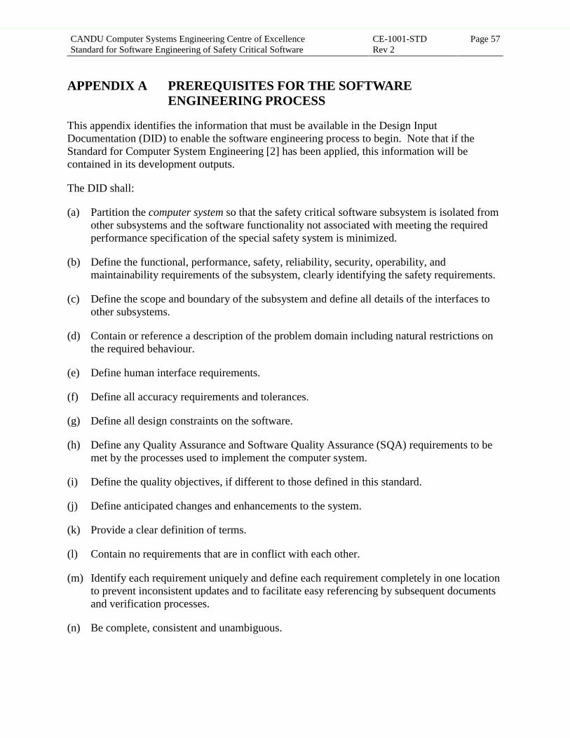
CANDU Computer Systems Engineering Centre of ExcellenceStandard for Software Engineering of Safety Critical Software
CE-1001-STDRev 2
Page 57
APPENDIX A PREREQUISITES FOR THE SOFTWAREENGINEERING PROCESS
This appendix identifies the information that must be available in the Design InputDocumentation (DID) to enable the software engineering process to begin. Note that if theStandard for Computer System Engineering [2] has been applied, this information will becontained in its development outputs.
The DID shall:
(a) Partition the computer system so that the safety critical software subsystem is isolated fromother subsystems and the software functionality not associated with meeting the requiredperformance specification of the special safety system is minimized.
(b) Define the functional, performance, safety, reliability, security, operability, andmaintainability requirements of the subsystem, clearly identifying the safety requirements.
(c) Define the scope and boundary of the subsystem and define all details of the interfaces toother subsystems.
(d) Contain or reference a description of the problem domain including natural restrictions onthe required behaviour.
(e) Define human interface requirements.
(f) Define all accuracy requirements and tolerances.
(g) Define all design constraints on the software.
(h) Define any Quality Assurance and Software Quality Assurance (SQA) requirements to bemet by the processes used to implement the computer system.
(i) Define the quality objectives, if different to those defined in this standard.
(j) Define anticipated changes and enhancements to the system.
(k) Provide a clear definition of terms.
(l) Contain no requirements that are in conflict with each other.
(m) Identify each requirement uniquely and define each requirement completely in one locationto prevent inconsistent updates and to facilitate easy referencing by subsequent documentsand verification processes.
(n) Be complete, consistent and unambiguous.
Approved for Issue - VERIFY STATUS PRIOR TO USE

CANDU Computer Systems Engineering Centre of ExcellenceStandard for Software Engineering of Safety Critical Software
CE-1001-STDRev 2
Page 58
(o) Define the reliability requirements of the software in a form useful for reliabilityqualification.
(p) Define all failure modes (identified by a hazards analysis of the computer system), and theappropriate response to them and identify any degraded operation modes required to behandled.
(q) Limit and localize the use of complex calculations upon which safety critical decisionsdepend.
(r) Contain or reference a revision history.
Approved for Issue - VERIFY STATUS PRIOR TO USE

CANDU Computer Systems Engineering Centre of ExcellenceStandard for Software Engineering of Safety Critical Software
CE-1001-STDRev 2
Page 59
APPENDIX B RATIONALE FOR THE REQUIREMENTS OF THISSTANDARD
In this standard, a software product is considered to include the full set of development outputs.The overall quality of a software product is determined by the extent to which the productachieves a set of desired quality objectives.
These quality objectives can be built into a software product by adhering to a process governedby some software engineering principles, and can be measured in a software product by a set ofmore readily assessable quality attributes.
This standard defines a set of activities and specific requirements that are derived from thequality attributes and software engineering principles defined in the following sections. Theseattributes are used to describe development outputs only, because the purpose of the verification,validation and support processes is to provide assurance that the quality attributes of thedevelopment outputs are achieved.
Coverage of the quality objectives by the requirements on the development outputs isdocumented in the last section of this appendix.
Approved for Issue - VERIFY STATUS PRIOR TO USE

CANDU Computer Systems Engineering Centre of ExcellenceStandard for Software Engineering of Safety Critical Software
CE-1001-STDRev 2
Page 60
B.1 Quality Objectives
The quality objectives listed below consist of primary and secondary objectives. The secondaryquality objectives shall only be considered if they do not compromise the primary qualityobjectives.
The primary quality objectives are:
Safety: A quality objective that requires that the system function in accordance with itsrequirements, in a consistent and predictable manner, under all conditions. When thesystem can no longer perform its required role, this quality objective requires that it act tomaintain the equipment and processes it controls in a safe state in all situations. Thisobjective implies the quality attributes completeness, correctness, predictability,robustness, understandability, and verifiability.
Functionality: A quality objective that requires that the system implement all requiredbehaviour and meet the performance requirements. This objective implies the qualityattributes completeness, correctness, understandability, and verifiability.
Reliability: A quality objective that requires that the system perform its required behavioursuch that the probability of it successfully performing that behaviour is consistent withthe reliability requirements identified. This objective implies the quality attributespredictability and robustness.
Maintainability: A quality objective that requires that the system be structured so that thoseitems most likely to require modification can be changed reliably and efficiently. Thisquality objective also requires the rationale for design decisions be evident to a thirdparty. This objective implies the quality attributes consistency, modifiability, modularity,structuredness, traceability, understandability and verifiability.
Reviewability: A quality objective that requires that the system be developed and documentedso that it can be systematically inspected by a third party for conformance torequirements. This objective implies the quality attributes consistency, modularity,structuredness, traceability, understandability and verifiability.
The secondary quality objectives are:
Portability: A quality objective that requires that the software be capable of being transferred todifferent environments to the degree required by users. This objective does not directlyimply any specific quality attributes.
Usability: A quality objective that requires that the system be easy and efficient to use, easy tolearn, easy to remember, acceptable to users, and one which leads to few errors. Thisobjective implies the quality attributes predictability and understandability.
Efficiency: A quality objective that requires that the system achieve an acceptable level ofperformance within the identified constraints. This objective does not directly imply anyspecific quality attributes.
Approved for Issue - VERIFY STATUS PRIOR TO USE

CANDU Computer Systems Engineering Centre of ExcellenceStandard for Software Engineering of Safety Critical Software
CE-1001-STDRev 2
Page 61
B.2 Quality Attributes
The quality attributes are:
Completeness: A quality attribute that refers to the extent to which all of the requiredbehaviour and design constraints are present and fully developed in the developmentoutputs.
Consistency: A quality attribute that refers to the extent to which the development outputscontain uniform notations, terminology, comments, symbology, and implementationtechniques.
Correctness: A quality attribute that refers to the ability of the development outputs todescribe or produce the specified outputs when given the specified inputs, and the extentto which they match or satisfy the requirements in the development inputs.
Modifiability: A quality attribute that refers to the characteristics of the development outputswhich facilitate the incorporation of changes.
Modularity: A quality attribute that refers to the extent to which the development output iscomposed of discrete components such that a change to one component has minimalimpact on the others.
Predictability: A quality attribute that refers to the extent to which the behaviour andperformance of the system are deterministic for a specified set of inputs.
Robustness: A quality attribute that refers to the extent to which the development outputsrequire and implement the ability to continue to perform despite some subsystem failure.
Structuredness: A quality attribute that refers to the extent to which the development outputspossess a definite pattern in their interdependent parts. This implies that the design hasproceeded in an orderly and systematic manner (e.g., top-down design), has minimizedcoupling between modules and subsystems, and that standard control structures have beenused to produced a well structured system.
Traceability: A quality attribute that refers to those characteristics of the developmentoutputs that provide a thread to their antecedent and subsequent documents. It also refersto the ability to trace the design decision history and reasons for changes.
Understandability: A quality attribute that refers to the extent to which the meaning of thedevelopment outputs are clear to a third party.
Verifiability: A quality attribute that refers to the extent to which the development outputshave been created to facilitate verification using both static methods and testing.
Approved for Issue - VERIFY STATUS PRIOR TO USE
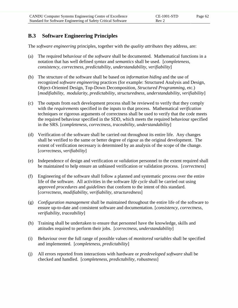
CANDU Computer Systems Engineering Centre of ExcellenceStandard for Software Engineering of Safety Critical Software
CE-1001-STDRev 2
Page 62
B.3 Software Engineering Principles
The software engineering principles, together with the quality attributes they address, are:
(a) The required behaviour of the software shall be documented. Mathematical functions in anotation that has well defined syntax and semantics shall be used. [completeness,consistency, correctness, predictability, understandability, verifiability]
(b) The structure of the software shall be based on information hiding and the use ofrecognized software engineering practices (for example: Structured Analysis and Design,Object-Oriented Design, Top-Down Decomposition, Structured Programming, etc.)[modifiability, modularity, predictability, structuredness, understandability, verifiability]
(c) The outputs from each development process shall be reviewed to verify that they complywith the requirements specified in the inputs to that process. Mathematical verificationtechniques or rigorous arguments of correctness shall be used to verify that the code meetsthe required behaviour specified in the SDD, which meets the required behaviour specifiedin the SRS. [completeness, correctness, traceability, understandability]
(d) Verification of the software shall be carried out throughout its entire life. Any changesshall be verified to the same or better degree of rigour as the original development. Theextent of verification necessary is determined by an analysis of the scope of the change.[correctness, verifiability]
(e) Independence of design and verification or validation personnel to the extent required shallbe maintained to help ensure an unbiased verification or validation process. [correctness]
(f) Engineering of the software shall follow a planned and systematic process over the entirelife of the software. All activities in the software life cycle shall be carried out usingapproved procedures and guidelines that conform to the intent of this standard.[correctness, modifiability, verifiability, structuredness]
(g) Configuration management shall be maintained throughout the entire life of the software toensure up-to-date and consistent software and documentation. [consistency, correctness,verifiability, traceability]
(h) Training shall be undertaken to ensure that personnel have the knowledge, skills andattitudes required to perform their jobs. [correctness, understandability]
(i) Behaviour over the full range of possible values of monitored variables shall be specifiedand implemented. [completeness, predictability]
(j) All errors reported from interactions with hardware or predeveloped software shall bechecked and handled. [completeness, predictability, robustness]
Approved for Issue - VERIFY STATUS PRIOR TO USE

CANDU Computer Systems Engineering Centre of ExcellenceStandard for Software Engineering of Safety Critical Software
CE-1001-STDRev 2
Page 63
(k) The software design shall be as conservative and simple as possible, while meeting allrequirements and retaining spare capacity for anticipated changes. [modifiability,understandability, verifiability]
(l) Analyses shall be performed to identify and evaluate safety hazards associated with thecomputer system with the aim of either eliminating them or assisting in the reduction of anyassociated risks. [robustness]
(m) Reliability of the safety critical software shall be demonstrated using a statistically valid,trajectory-based methodology in which a reliability hypothesis is proven to the degree ofconfidence required. [robustness]
(n) Adequate testing shall be performed to meet predefined test coverage criteria. [correctness,robustness]
Approved for Issue - VERIFY STATUS PRIOR TO USE

CANDU Computer Systems Engineering Centre of ExcellenceStandard for Software Engineering of Safety Critical Software
CE-1001-STDRev 2
Page 64
B.4 Coverage of the Quality Attributes
B.4.1 Coverage of the Quality Attributes by the SRS
To ensure that the output of the design and coding activities fulfil their acceptance criteria for thequality objectives safety, functionality, reliability, reviewability and maintainability, the SRSshall have the following quality attributes: completeness, consistency, correctness, modifiability,robustness, traceability, understandability and verifiability. Coverage of these quality attributesis documented in the following table.
Requirements on the SRS
com
plet
enes
s
cons
iste
ncy
corr
ectn
ess
mod
ifia
bilit
y
mod
ular
ity
pred
icta
bilit
y
robu
stne
ss
stru
ctur
edne
ss
trac
eabi
lity
unde
rsta
ndab
ility
veri
fiab
ility
3.1.2.a - Specify all requirements from the DID ¥3.1.2.b - Specify additional requirements ¥ ¥3.1.2.c - Describe context ¥3.1.2.d - Identify external properties ¥ ¥3.1.2.e - Describe I/O characteristics ¥3.1.2.f - Describe I/O relationships ¥3.1.2.g - Define behaviour ¥ ¥ ¥ ¥3.1.2.h - Specify exception response ¥ ¥3.1.2.i - Specify fault tolerance ¥3.1.2.j - Specify timing tolerances ¥3.1.2.k - Identify anticipated changes ¥ ¥3.1.2.l - Identify design constraints ¥3.1.2.m - Requirements and constraints only ¥ ¥3.1.2.n - No conflicts ¥ ¥ ¥ ¥3.1.2.o - Unique requirements ¥ ¥3.1.2.p - Identify requirements uniquely ¥3.1.2.q - Reference design notes ¥3.1.2.r - Demonstrate mapping ¥3.1.2.s - Conform to standards ¥ ¥ ¥3.1.2.t - Use consistent terminology ¥ ¥ ¥3.1.2.u - Enable role determination ¥ ¥ ¥ ¥
Approved for Issue - VERIFY STATUS PRIOR TO USE
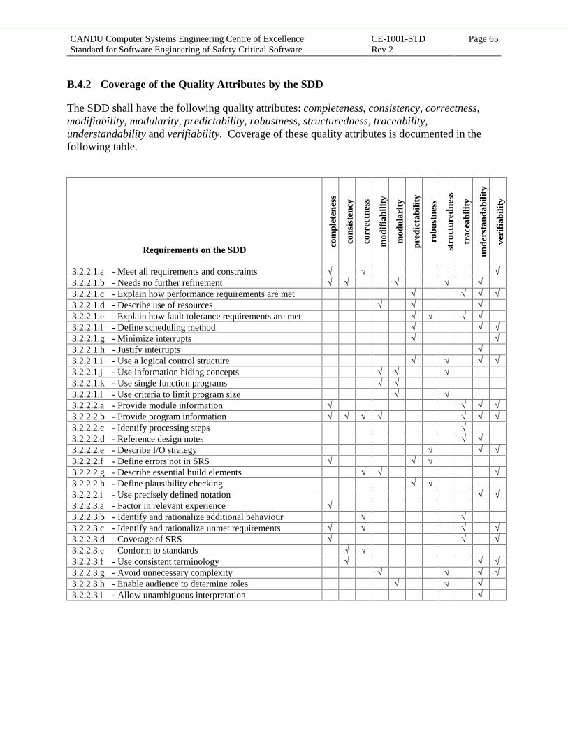
CANDU Computer Systems Engineering Centre of ExcellenceStandard for Software Engineering of Safety Critical Software
CE-1001-STDRev 2
Page 65
B.4.2 Coverage of the Quality Attributes by the SDD
The SDD shall have the following quality attributes: completeness, consistency, correctness,modifiability, modularity, predictability, robustness, structuredness, traceability,understandability and verifiability. Coverage of these quality attributes is documented in thefollowing table.
Requirements on the SDD
com
plet
enes
s
cons
iste
ncy
corr
ectn
ess
mod
ifia
bilit
y
mod
ular
ity
pred
icta
bilit
y
robu
stne
ss
stru
ctur
edne
ss
trac
eabi
lity
unde
rsta
ndab
ility
veri
fiab
ility
3.2.2.1.a - Meet all requirements and constraints ¥ ¥ ¥3.2.2.1.b - Needs no further refinement ¥ ¥ ¥ ¥ ¥3.2.2.1.c - Explain how performance requirements are met ¥ ¥ ¥ ¥3.2.2.1.d - Describe use of resources ¥ ¥ ¥3.2.2.1.e - Explain how fault tolerance requirements are met ¥ ¥ ¥ ¥3.2.2.1.f - Define scheduling method ¥ ¥ ¥3.2.2.1.g - Minimize interrupts ¥ ¥3.2.2.1.h - Justify interrupts ¥3.2.2.1.i - Use a logical control structure ¥ ¥ ¥ ¥3.2.2.1.j - Use information hiding concepts ¥ ¥ ¥3.2.2.1.k - Use single function programs ¥ ¥3.2.2.1.l - Use criteria to limit program size ¥ ¥3.2.2.2.a - Provide module information ¥ ¥ ¥ ¥3.2.2.2.b - Provide program information ¥ ¥ ¥ ¥ ¥ ¥ ¥3.2.2.2.c - Identify processing steps ¥3.2.2.2.d - Reference design notes ¥ ¥3.2.2.2.e - Describe I/O strategy ¥ ¥ ¥3.2.2.2.f - Define errors not in SRS ¥ ¥ ¥3.2.2.2.g - Describe essential build elements ¥ ¥ ¥3.2.2.2.h - Define plausibility checking ¥ ¥3.2.2.2.i - Use precisely defined notation ¥ ¥3.2.2.3.a - Factor in relevant experience ¥3.2.2.3.b - Identify and rationalize additional behaviour ¥ ¥3.2.2.3.c - Identify and rationalize unmet requirements ¥ ¥ ¥ ¥3.2.2.3.d - Coverage of SRS ¥ ¥ ¥3.2.2.3.e - Conform to standards ¥ ¥3.2.2.3.f - Use consistent terminology ¥ ¥ ¥3.2.2.3.g - Avoid unnecessary complexity ¥ ¥ ¥ ¥3.2.2.3.h - Enable audience to determine roles ¥ ¥ ¥3.2.2.3.i - Allow unambiguous interpretation ¥
Approved for Issue - VERIFY STATUS PRIOR TO USE
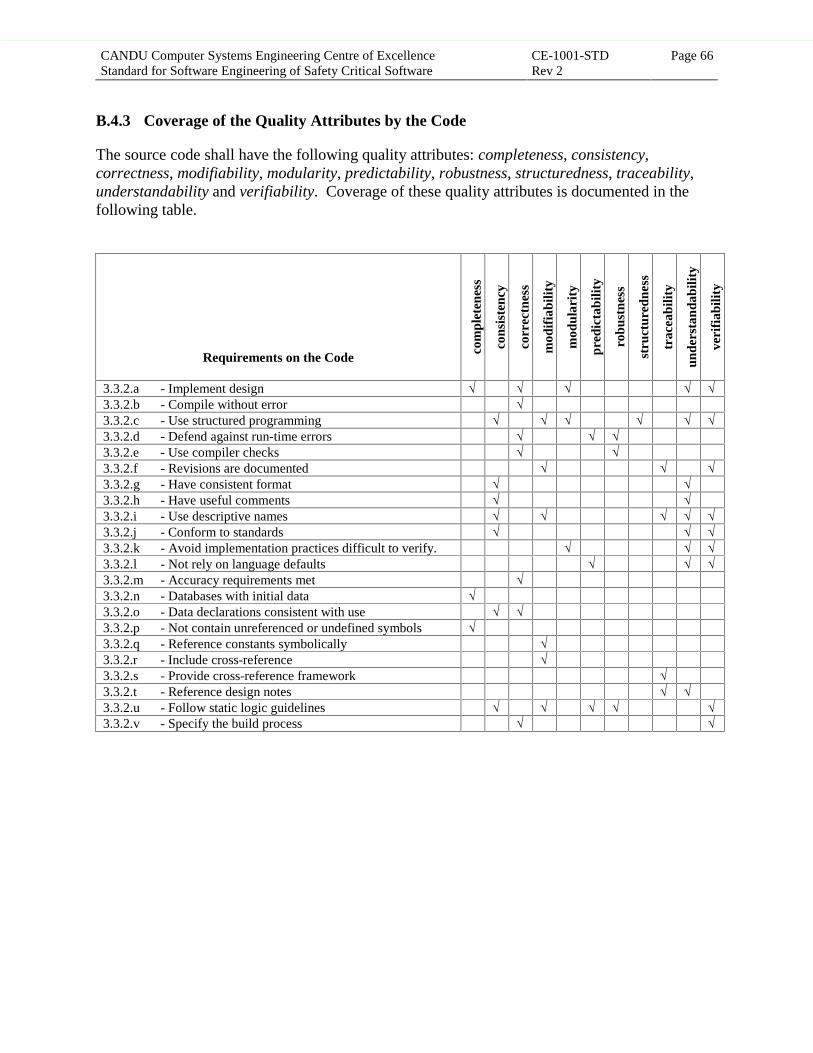
CANDU Computer Systems Engineering Centre of ExcellenceStandard for Software Engineering of Safety Critical Software
CE-1001-STDRev 2
Page 66
B.4.3 Coverage of the Quality Attributes by the Code
The source code shall have the following quality attributes: completeness, consistency,correctness, modifiability, modularity, predictability, robustness, structuredness, traceability,understandability and verifiability. Coverage of these quality attributes is documented in thefollowing table.
Requirements on the Code
com
plet
enes
s
cons
iste
ncy
corr
ectn
ess
mod
ifia
bilit
y
mod
ular
ity
pred
icta
bilit
y
robu
stne
ss
stru
ctur
edne
ss
trac
eabi
lity
unde
rsta
ndab
ility
veri
fiab
ility
3.3.2.a - Implement design ¥ ¥ ¥ ¥ ¥3.3.2.b - Compile without error ¥3.3.2.c - Use structured programming ¥ ¥ ¥ ¥ ¥ ¥3.3.2.d - Defend against run-time errors ¥ ¥ ¥3.3.2.e - Use compiler checks ¥ ¥3.3.2.f - Revisions are documented ¥ ¥ ¥3.3.2.g - Have consistent format ¥ ¥3.3.2.h - Have useful comments ¥ ¥3.3.2.i - Use descriptive names ¥ ¥ ¥ ¥ ¥3.3.2.j - Conform to standards ¥ ¥ ¥3.3.2.k - Avoid implementation practices difficult to verify. ¥ ¥ ¥3.3.2.l - Not rely on language defaults ¥ ¥ ¥3.3.2.m - Accuracy requirements met ¥3.3.2.n - Databases with initial data ¥3.3.2.o - Data declarations consistent with use ¥ ¥3.3.2.p - Not contain unreferenced or undefined symbols ¥3.3.2.q - Reference constants symbolically ¥3.3.2.r - Include cross-reference ¥3.3.2.s - Provide cross-reference framework ¥3.3.2.t - Reference design notes ¥ ¥3.3.2.u - Follow static logic guidelines ¥ ¥ ¥ ¥ ¥3.3.2.v - Specify the build process ¥ ¥
Approved for Issue - VERIFY STATUS PRIOR TO USE

CANDU Computer Systems Engineering Centre of ExcellenceStandard for Software Engineering of Safety Critical Software
CE-1001-STDRev 2
Page 67
INDEX
accuracy ................................................ 8, 14, 45, 57activities 3, 27, 28, 31, 32, 34, 37, 38, 42, 46, 49, 59,
62, 64animation ......................................................... 31, 39
baseline ........................................................... 34, 39Baseline Release Package Index (BRPI) ......... 29, 39boundary ....................................... 20, 39, 43, 44, 57
change control ................................................. 34, 39change request ..................................... 29, 34, 38, 39code iii, 11, 12, 17, 18, 19, 20, 21, 23, 24, 26, 34, 39,
40, 42, 48, 50, 66code implementation ......................... 1, 3, 14, 17, 39code review ......................... vii, 6, 15, 17, 32, 36, 41Code Review Report (CRR) ........................ 6, 17, 41code verification .................................................... 36Code Verification Report (CVR) ................ 6, 18, 41cohesion .................................................... 10, 39, 40commissioning ................................................. iii, 31completeness ................40, 41, 60, 61, 62, 64, 65, 66complexity ................................................... v, 31, 65configuration 1, 21, 29, 34, 37, 38, 39, 40, 42, 43,
46, 47, 49, 50configuration control ..................... 39, 40, 42, 47, 50configuration management ........ 1, 34, 37, 38, 40, 49consistency .........................40, 60, 61, 62, 64, 65, 66controlled variable ................................ 8, 40, 43, 45convention ................................................... 1, 13, 44correctness ..............40, 50, 60, 61, 62, 63, 64, 65, 66coupling ........................................ 10, 39, 40, 49, 61
deliverable ................................................. 33, 34, 41design iii, iv, 1, 3, 6, 7, 8, 9, 10, 11, 12, 14, 15, 16,
23, 24, 30, 31, 33, 35, 36, 39, 40, 41, 42, 43, 44,45, 47, 48, 49, 50, 57, 60, 61, 62, 63, 64, 65, 66
design constraint 7, 8, 9, 12, 15, 16, 40, 41, 57, 61,64
Design Input Documentation (DID) 2, 3, 7, 8, 15, 16,22, 23, 24, 28, 30, 34, 41, 57, 64
design notes ................6, 8, 11, 14, 33, 41, 64, 65, 66design review .......... vii, 6, 15, 16, 31, 32, 36, 41, 42Design Review Report (DRR) .................... 6, 16, 41design verification ........................................... 31, 36Design Verification Report (DVR) ............. 6, 18, 41development ii, 3, 7, 28, 30, 31, 32, 33, 36, 37, 39,
40, 41, 42, 43, 44, 45, 46, 47, 48, 49, 50, 57, 59,61, 62
development output ii, 3, 36, 40, 41, 42, 44, 45, 46,49, 50, 57, 59, 61
development process ..........2, 3, 7, 32, 36, 41, 45, 62
efficiency ......................................................... 42, 60
failure .................................. 8, 23, 24, 42, 46, 58, 61fault ................................................... 8, 9, 42, 64, 65fault tolerance .................................... 8, 9, 42, 64, 65four variable model ............................. 40, 43, 44, 45functionality 10, 13, 16, 18, 30, 31, 43, 50, 57, 60,
64
graceful degradation ...................................... 8, 9, 43guideline 1, 12, 13, 14, 16, 17, 36, 37, 43, 44, 51, 52,
62, 66
hazards analysis v, vii, viii, 1, 3, 6, 8, 15, 23, 32, 43,58
hold point ........................................................ 31, 43
independence ................ v, viii, 25, 28, 32, 34, 46, 62input variable .......................................... ii, 8, 11, 43inspection ........................................................ 43, 50Integration Test Procedures (ITP) ......... 6, 21, 22, 44Integration Test Report (ITR) ............... 6, 21, 22, 44
life cycle .................................. 28, 30, 44, 54, 55, 62
maintainability ...................... 7, 9, 30, 44, 57, 60, 64methodology ..............v, 1, 32, 35, 36, 44, 46, 54, 63modifiability .................44, 60, 61, 62, 63, 64, 65, 66modularity ..........................44, 60, 61, 62, 64, 65, 66module ...........................9, 10, 19, 43, 44, 45, 50, 65monitored variable ................................ 8, 43, 44, 62
operability ............................................... 7, 9, 44, 57output variable .................................. ii, 8, 11, 43, 45
performance ii, 1, 7, 9, 13, 21, 22, 42, 43, 45, 46, 47,50, 57, 60, 61, 65
personnel ..........26, 28, 29, 31, 32, 33, 35, 37, 47, 62planning .......................................... 1, 28, 30, 45, 49policy statement .................................................... 33portability ........................................................ 45, 60predictability ......................45, 60, 61, 62, 64, 65, 66procedure ............................................ 26, 37, 45, 49program v, 9, 10, 11, 12, 13, 14, 19, 20, 39, 40, 41,
42, 44, 45, 46, 48, 49, 65Project Execution Plan (PEP) ......................... 28, 45prototyping ................................................ 30, 31, 45
Approved for Issue - VERIFY STATUS PRIOR TO USE

CANDU Computer Systems Engineering Centre of ExcellenceStandard for Software Engineering of Safety Critical Software
CE-1001-STDRev 2
Page 68
qualification iii, v, viii, 1, 2, 3, 6, 15, 24, 25, 26, 32,33, 35, 45, 46, 48, 58
quality attribute iv, 40, 44, 45, 46, 49, 50, 59, 60, 61,62, 64, 65, 66
quality objective iii, 42, 43, 44, 45, 46, 47, 50, 57,59, 60, 64
real-time .................................................... v, 1, 2, 46record ...................................... 29, 33, 34, 35, 38, 46regression testing ............................................ 36, 46release ................................................... 3, 32, 38, 46reliability iii, v, vii, viii, 1, 3, 6, 7, 9, 15, 23, 24, 25,
30, 31, 32, 46, 47, 48, 53, 55, 56, 57, 58, 60, 63,64
reliability hypothesis ............................ iii, 24, 46, 63reliability qualification v, vii, viii, 1, 3, 6, 15, 24, 25,
32, 46, 48, 58requirements ii, iii, v, 1, 2, 3, 6, 7, 8, 9, 10, 11, 12,
14, 15, 16, 17, 18, 19, 20, 21, 22, 23, 24, 25, 26,27, 28, 30, 31, 32, 33, 35, 36, 40, 41, 42, 43, 45,46, 47, 48, 49, 50, 57, 58, 59, 60, 61, 62, 63, 64,65, 66
requirements definition ....................................... 1, 3requirements review ............ vii, 6, 15, 16, 32, 36, 47Requirements Review Report (RRR) .... 6, 15, 16, 47review ii, vii, viii, 1, 3, 6, 15, 16, 17, 23, 25, 31, 32,
34, 36, 41, 42, 43, 46, 47review reports ........................................................ 25reviewability ....................................... 30, 46, 60, 64revision .................................................. ii, 13, 38, 58robustness .................9, 46, 60, 61, 62, 63, 64, 65, 66
safety 1, v, 1, 2, 6, 7, 9, 21, 23, 24, 30, 35, 39, 46,47, 48, 51, 52, 53, 54, 55, 56, 57, 58, 60, 63, 64
safety critical ..................v, 1, 2, 6, 39, 47, 57, 58, 63safety design principle .............................. 23, 24, 35safety related ......................................................... 47safety requirement ........................................... 47, 57safety-related ......................................................... 54security ........................................ 7, 9, 21, 38, 47, 57semantics ................................... 8, 11, 12, 47, 49, 62Software Design Description (SDD) iii, viii, 6, 8, 9,
10, 11, 12, 13, 14, 16, 17, 18, 19, 20, 21, 23, 34,36, 47, 53, 62, 65
Software Development Plan (SDP) vii, 3, 6, 11, 28,29, 30, 31, 32, 33, 34, 35, 37, 47, 52
software engineering 1, ii, iii, v, viii, 1, 2, 3, 6, 16,17, 28, 29, 30, 32, 39, 41, 45, 48, 51, 52, 53, 54,55, 56, 57, 59, 62
Software Quality Assurance (SQA) ...................... 57Software Requirements Specification (SRS) viii, 6,
7, 9, 11, 12, 15, 16, 17, 18, 21, 23, 24, 32, 34, 36,48, 53, 54, 62, 64, 65
Standards and Procedures Handbook (SPH) iii, vii,3, 6, 7, 8, 9, 12, 13, 15, 16, 17, 18, 20, 21, 22, 23,26, 27, 28, 29, 30, 34, 35, 37, 48
structured programming ............................ 13, 48, 66structuredness .....................49, 60, 61, 62, 64, 65, 66support iii, 2, 3, 25, 26, 27, 28, 30, 31, 32, 33, 34, 36,
38, 41, 45, 49, 59support output ........................................................ iiisupport process .................2, 3, 28, 31, 32, 36, 41, 59syntax ........................................ 8, 11, 12, 47, 49, 62systematic code verification vii, 6, 17, 18, 32, 36, 47systematic design verification vii, 6, 17, 18, 32, 36,
47systematic verification .....vii, viii, 1, 3, 6, 15, 17, 25
terminology ................2, 9, 12, 37, 39, 40, 61, 64, 65testing iii, vii, viii, 1, 3, 6, 15, 19, 20, 21, 22, 31, 32,
36, 37, 42, 46, 47, 48, 49, 50, 51, 52, 54, 55, 56,61, 63
tolerance ...................................... 8, 9, 42, 57, 64, 65traceability ..............40, 41, 49, 60, 61, 62, 64, 65, 66training .... vii, 1, 6, 28, 29, 30, 31, 32, 35, 38, 49, 62training record ........................................... 29, 35, 38
understandability ..........50, 60, 61, 62, 63, 64, 65, 66Unit Test Procedures (UTP) ........................ 6, 20, 50Unit Test Report (UTR) .............................. 6, 20, 50usability ........................................................... 50, 60
validation vii, 2, 3, 6, 15, 19, 22, 23, 25, 27, 31, 32,41, 49, 50, 54, 59, 62
validation test ........................................................ 22Validation Test Procedures (VTP) .............. 6, 22, 50Validation Test Report (VTR) .............. 6, 22, 23, 50verifiability ...................50, 60, 61, 62, 63, 64, 65, 66verification iii, v, vii, viii, 1, 2, 3, 6, 15, 17, 18, 25,
27, 28, 30, 31, 32, 33, 34, 36, 37, 41, 47, 49, 50,54, 55, 57, 59, 61, 62
verification output iii, 16, 17, 18, 19, 24, 25, 26, 27,36
verification process ............15, 17, 18, 27, 36, 57, 62
walkthrough .............................................. 31, 43, 50
Approved for Issue - VERIFY STATUS PRIOR TO USE