Embed Size (px)
DESCRIPTION
Service Manual
Citation preview

7/18/2019 Canon Fax Board N1
http://slidepdf.com/reader/full/canon-fax-board-n1 1/125
SERVICE
MANUAL
imageRUNNER
C3100
Super G3FAX Board-N1
COPYRIGHT 2003 CANON INC. CANON imageRUNNERC3100 REV. 0 PRINTED IN U.S.A.
JAN 2004
REV. 0

7/18/2019 Canon Fax Board N1
http://slidepdf.com/reader/full/canon-fax-board-n1 2/125
Application
This manual has been issued by Canon Inc. for qualified persons to learn technical theory, installation,
maintenance, and repair of products. This manual covers all localities where the products are sold. For
this reason, there may be information in this manual that does not apply to your locality.
Corrections
This manual may contain technical inaccuracies or typographical errors due to improvements or changes
in products. When changes occur in applicable products or in the contents of this manual, Canon will
release technical information as the need arises. In the event of major changes in the contents of this
manual over a long or short period, Canon will issue a new edition of this manual.
The following paragraph does not apply to any countries where such provisions are inconsistent with
local law.
Trademarks
The product names and company names used in this manual are the registered trademarks of the
individual companies.
Copyright
This manual is copyrighted with all rights reserved. Under the copyright laws, this manual may not be
copied, reproduced or translated into another language, in whole or in part, without the written consent
of Canon Inc.
COPYRIGHT © 2001 CANON INC.
Printed in Japan
Caution
Use of this manual should be strictly supervised to avoid disclosure of confidential information.

7/18/2019 Canon Fax Board N1
http://slidepdf.com/reader/full/canon-fax-board-n1 3/125
Introduction
Symbols Used
This documentation uses the following symbols to indicate special information:
Symbol Description
Indicates an item of a non-specific nature, possibly classified as Note,
Caution, or Warning.
Indicates an item requiring care to avoid electric shocks.
Indicates an item requiring care to avoid combustion (fire).
Indicates an item prohibiting disassembly to avoid electric shocks or
problems.
Indicates an item requiring disconnection of the power plug from the electricoutlet.
Indicates an item intended to provide notes assisting the understanding of the
topic in question.
Indicates an item of reference assisting the understanding of the topic in
question.
Provides a description of a service mode.
Provides a description of the nature of an error indication.
Memo
REF.
7/18/2019 Canon Fax Board N1
http://slidepdf.com/reader/full/canon-fax-board-n1 4/125
Introduction
The following rules apply throughout this Service Manual:
1. Each chapter contains sections explaining the purpose of specific functions and the
relationship between electrical and mechanical systems with reference to the timing of
operation.
In the diagrams, represents the path of mechanical drive; where a signal name
accompanies the symbol, the arrow indicates the direction of the electric
signal.
The expression "turn on the power" means flipping on the power switch, closing the front
door, and closing the delivery unit door, which results in supplying the machine with
power.
2. In the digital circuits, '1'is used to indicate that the voltage level of a given signal is
"High", while '0' is used to indicate "Low".(The voltage value, however, differs from
circuit to circuit.) In addition, the asterisk (*) as in "DRMD*" indicates that the DRMD
signal goes on when '0'.
In practically all cases, the internal mechanisms of a microprocessor cannot be checked
in the field. Therefore, the operations of the microprocessors used in the machines are
not discussed: they are explained in terms of from sensors to the input of the DC
controller PCB and from the output of the DC controller PCB to the loads.
The descriptions in this Service Manual are subject to change without notice for product
improvement or other purposes, and major changes will be communicated in the form of
Service Information bulletins.
All service persons are expected to have a good understanding of the contents of this
Service Manual and all relevant Service Information bulletins and be able to identify and
isolate faults in the machine."

7/18/2019 Canon Fax Board N1
http://slidepdf.com/reader/full/canon-fax-board-n1 5/125
7/18/2019 Canon Fax Board N1
http://slidepdf.com/reader/full/canon-fax-board-n1 6/125
Contents
Contents
Chapter 1 Specifications
1.1 Product Specifications ............................................................................................... 1-1
1.1.1 Specifications...................................................................................................... 1-1
Chapter 2 Functions
2.1 Basic Construction..................................................................................................... 2-1
2.1.1 Overview............................................................................................................. 2-1
2.1.2 G3 FAX Control PCB......................................................................................... 2-2
2.1.3 NCU PCB............................................................................................................ 2-3
Chapter 3 Installation
3.1 Making Pre-Checks.................................................................................................... 3-1
3.1.1 Checking the Contents ........................................................................................ 3-1
3.2 Installation Procedure ................................................................................................ 3-4
3.2.1 Preparing the Host Machine................................................................................ 3-4
3.2.2 Connecting the Connector and Mounting the Modular Unit .............................. 3-7
3.2.3 Mounting the G3 Fax Unit ................................................................................ 3-10
3.2.4 Mounting the Speaker Unit ............................................................................... 3-12
3.2.5 After the Work .................................................................................................. 3-13
3.3 Checking the Operation ........................................................................................... 3-15
3.3.1 Type Settings..................................................................................................... 3-153.3.2 Settings According to Line Type ...................................................................... 3-15
3.3.3 Fax Communication Test .................................................................................. 3-15
Chapter 4 Parts Replacement Procedure
4.1 Removing from the Host Machine............................................................................. 4-1
4.1.1 FAX Unit .............................................................................................................4-1

7/18/2019 Canon Fax Board N1
http://slidepdf.com/reader/full/canon-fax-board-n1 7/125
Contents
Chapter 5 Service Mode
5.1 Outline........................................................................................................................ 5-1
5.1.1 Service Mode Composition................................................................................. 5-1
5.1.2 Using Service Mode ............................................................................................ 5-15.1.3 Menu Items.......................................................................................................... 5-4
5.2 Setting of Bit Switch (SSSW).................................................................................... 5-7
5.2.1 Outline .................................................................................................................5-7
5.2.2 SSSW-SW01: Error/Copy Management .............................................................5-8
5.2.3 SSSW-SW03: Setting of Echo Measures ...........................................................5-9
5.2.4 SSSW-SW04: Setting of Communication Trouble Measures ..........................5-11
5.2.5 SSSW-SW05: Setting of Standard Functions (DIS signal) ...............................5-13
5.2.6 SSSW-SW12: Setting of Page Timer ...............................................................5-14
5.2.7 SSSW-SW14: Setting of Inch/Millimeter-base Resolution ..............................5-16
5.2.8 SSSW-SW25: Setting of Report Indication Functions .....................................5-17
5.2.9 SSSW-SW26: Setting of transmission functions ..............................................5-18
5.2.10 SSSW-SW28: Procedure Setting for V.8/V.34 ..............................................5-19
5.3 Setting of Menu Switch (MENU) ............................................................................ 5-21
5.3.1 Menu Switch Composition................................................................................ 5-21
5.3.2 <005: NL Equalizer>......................................................................................... 5-21
5.3.3 <006: Telephone Line Monitor>....................................................................... 5-22
5.3.4 <007: ATT Transmission Level>...................................................................... 5-225.3.5 <008: V.34 Modulation Speed Upper Limit>................................................... 5-23
5.3.6 <009: V.34 Data Speed Upper Limit> .............................................................. 5-23
5.4 Setting of Numeric Parameter (NUMERIC Param.) ............................................... 5-24
5.4.1 Numerical Parameter Composition................................................................... 5-24
5.4.2 <002: RTN transmission condition (1)><003: RTN transmission condition
(2)><004: RTN transmission condition (3)> ......................................................... 5-25
5.4.3 <005: NCC pause length (pre-ID code)> .......................................................... 5-26
5.4.4 <006: NCC pause length (post-ID code)> ........................................................ 5-26
5.4.5 <007: pre-pause length at time of ring>............................................................ 5-26
5.4.6 <009: number of comparison digits of source telephone number and target
telephone number> ................................................................................................. 5-26
5.4.7 <010: line connection identification length> .................................................... 5-26
5.4.8 <011: T.30 T1 timer (for reception)>................................................................ 5-26
5.4.9 <013: T.30 EOL timer>..................................................................................... 5-27
5.4.10 <027: V.21 low-speed flag preamble identification length> .......................... 5-27
5.5 Setting of Destination (TYPE)................................................................................. 5-28
5.5.1 Overview........................................................................................................... 5-28
5.6 Setting of Printer Functions (PRINTER)................................................................. 5-29

7/18/2019 Canon Fax Board N1
http://slidepdf.com/reader/full/canon-fax-board-n1 8/125
Contents
5.6.1 Setting of Bit Switch (SSSW) ...........................................................................5-29
5.6.2 Setting of Numeric Parameter (NUMERIC Param.) ........................................5-31
5.7 Initialization of Set Value (CLEAR) ....................................................................... 5-33
5.7.1 Overview........................................................................................................... 5-33
5.8 Default Settings........................................................................................................ 5-34
5.8.1 Default Settings................................................................................................. 5-34
5.9 Test Mode (TEST) ................................................................................................... 5-45
5.9.1 Outline ...............................................................................................................5-45
5.9.2 MODEM Test ...................................................................................................5-46
5.9.3 Function Test .....................................................................................................5-51
5.10 Service Report (REPORT)..................................................................................... 5-53
5.10.1 System Data List ............................................................................................. 5-53
5.10.2 System Dump List........................................................................................... 5-545.10.3 Error Transmission Report.............................................................................. 5-57
Chapter 6 Error Code
6.1 Overview.................................................................................................................... 6-1
6.1.1 Guide to Error Code............................................................................................ 6-1
6.2 User Error Code ......................................................................................................... 6-4
6.2.1 User Error Code .................................................................................................. 6-4
6.3 Service Error Code..................................................................................................... 6-5
6.3.1 Service Error Code.............................................................................................. 6-5

7/18/2019 Canon Fax Board N1
http://slidepdf.com/reader/full/canon-fax-board-n1 9/125

7/18/2019 Canon Fax Board N1
http://slidepdf.com/reader/full/canon-fax-board-n1 10/125
Chapter 1
Specifications

7/18/2019 Canon Fax Board N1
http://slidepdf.com/reader/full/canon-fax-board-n1 11/125

7/18/2019 Canon Fax Board N1
http://slidepdf.com/reader/full/canon-fax-board-n1 12/125
Contents
Contents
1.1 Product Specifications................................................................................1-1
1.1.1 Specifications ......................................................................................1-1

7/18/2019 Canon Fax Board N1
http://slidepdf.com/reader/full/canon-fax-board-n1 13/125

7/18/2019 Canon Fax Board N1
http://slidepdf.com/reader/full/canon-fax-board-n1 14/125
Chapter 1
1-1
1.1 Product Specifications
1.1.1 Specifications
T-1-1
Item Description
Communication G3
Line type Subscriber line (PSTN)
Modulation <G3 image signal>
ITU-T V.27ter (2.4Kbps, 4.8Kbps)
ITU-T V.29 (7.2Kbps, 9.6Kbps)
ITU-T V.17 (TC 7.2Kbps, TC 9.6Kbps, 12Kbps, 14.4Kbps)
ITU-T V.34 (2.4Kbps, 4.8Kbps, 7.2Kbps, 9.6Kbps, 12Kbps, 14.4Kbps,
16.8Kbps, 19.2Kbps, 21.6Kbps, 24Kbps, 26.4Kbps, 28.8Kbps, 31.2Kbps,
33.6Kbps)
<G3 procedure signal>
ITU-T V.21 No.2 (300bps)
ITU-T V.8, V.34 (300bps)
Transmission speed 33.6Kbps, 31.2Kbps, 28.8Kbps, 23.4Kbps, 24Kbps, 21.6Kbps, 19.2Kbps,
16.8Kbps, 14.4Kbps, 12Kbps, TC 9.6Kbps, TC7.2Kbps, 9.6Kbps,
7.2Kbps, 4.8Kbps, 2.4Kbps
auto fallback function
Coding method JBIG, MMR, MR, MH
G3-specific abridged procedure no
Modem IC conexant FM336
Error correction ITU-T ECM
Transmission original size A3, A4, A4R, A5, A5R, B4, B5, B5R, LTR, LTRR, LGL, 11×17, STMT,
STMTR
ADF: double-sided originals accepted
Scanning line density Standard (200 x 100 dpi): 8 dots/mm x 3.85 lines/mm
Fine (200 x 200 dpi):8 dots/mm x 7.7 lines/mm
7/18/2019 Canon Fax Board N1
http://slidepdf.com/reader/full/canon-fax-board-n1 15/125
Chapter 1
1-2
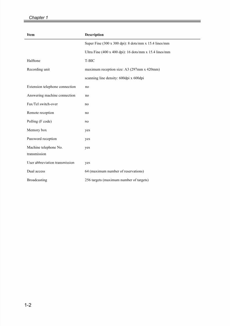
Super Fine (300 x 300 dpi): 8 dots/mm x 15.4 lines/mm
Ultra Fine (400 x 400 dpi): 16 dots/mm x 15.4 lines/mm
Halftone T-BIC
Recording unit maximum reception size: A3 (297mm x 420mm)
scanning line density: 600dpi x 600dpi
Extension telephone connection no
Answering machine connection no
Fax/Tel switch-over no
Remote reception no
Polling (F code) no
Memory box yes
Password reception yes
Machine telephone No.
transmission
yes
User abbreviation transmission yes
Dual access 64 (maximum number of reservations)
Broadcasting 256 targets (maximum number of targets)
Item Description

7/18/2019 Canon Fax Board N1
http://slidepdf.com/reader/full/canon-fax-board-n1 16/125
Chapter 2
Functions

7/18/2019 Canon Fax Board N1
http://slidepdf.com/reader/full/canon-fax-board-n1 17/125

7/18/2019 Canon Fax Board N1
http://slidepdf.com/reader/full/canon-fax-board-n1 18/125
Contents
Contents
2.1 Basic Construction .....................................................................................2-1
2.1.1 Overview.............................................................................................2-1
2.1.2 G3 FAX Control PCB .........................................................................2-2
2.1.3 NCU PCB............................................................................................2-3

7/18/2019 Canon Fax Board N1
http://slidepdf.com/reader/full/canon-fax-board-n1 19/125

7/18/2019 Canon Fax Board N1
http://slidepdf.com/reader/full/canon-fax-board-n1 20/125
Chapter 2
2-1
2.1 Basic Construction
2.1.1 Overview
The board is designed to enable a digital copier to serve as a high-performance multi-
functional machine (image processing functions and communication functions over the
telephone line).
It is capable of communicating at a maximum rate of 33.6 kbps, thanks to the presence of a
V.34-compliant modem (ITU-T).
F-2-1
[1] Super G3 Fax Board-N1
[2] Speaker unit
[3] Modular PCB
[2]
[1]
[3]
7/18/2019 Canon Fax Board N1
http://slidepdf.com/reader/full/canon-fax-board-n1 21/125
Chapter 2
2-2
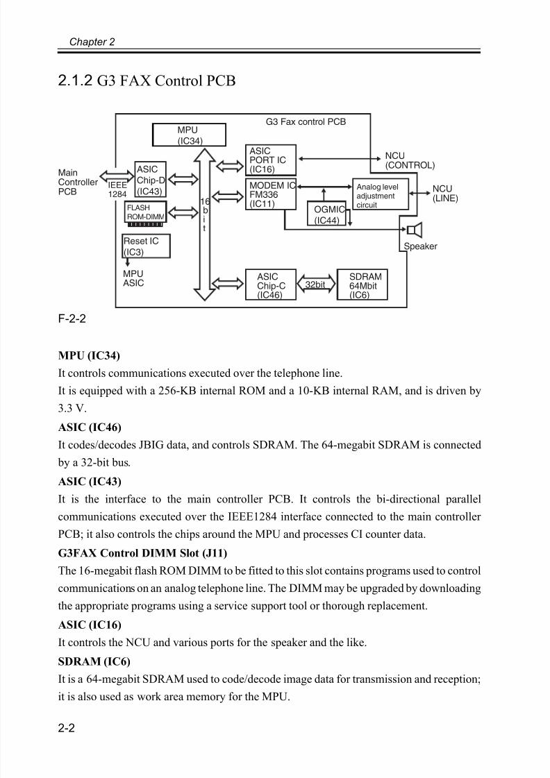
2.1.2 G3 FAX Control PCB
F-2-2
MPU (IC34)
It controls communications executed over the telephone line.
It is equipped with a 256-KB internal ROM and a 10-KB internal RAM, and is driven by
3.3 V.
ASIC (IC46)
It codes/decodes JBIG data, and controls SDRAM. The 64-megabit SDRAM is connected
by a 32-bit bus.
ASIC (IC43)
It is the interface to the main controller PCB. It controls the bi-directional parallel
communications executed over the IEEE1284 interface connected to the main controller
PCB; it also controls the chips around the MPU and processes CI counter data.
G3FAX Control DIMM Slot (J11)
The 16-megabit flash ROM DIMM to be fitted to this slot contains programs used to control
communications on an analog telephone line. The DIMM may be upgraded by downloading
the appropriate programs using a service support tool or thorough replacement.
ASIC (IC16)
It controls the NCU and various ports for the speaker and the like.
SDRAM (IC6)
It is a 64-megabit SDRAM used to code/decode image data for transmission and reception;it is also used as work area memory for the MPU.
MPUASIC
MPU(IC34)
ASICChip-D
(IC43)
ASICPORT IC(IC16)
MODEM ICFM336(IC11)
Analog leveladjustmentcircuit
ASICChip-C(IC46)
SDRAM64Mbit(IC6)
FLASH
ROM-DIMM
16bit
32bit
Reset IC
(IC3)
OGMIC(IC44)
Speaker
IEEE1284
MainControllerPCB
NCU(CONTROL)
NCU(LINE)
G3 Fax control PCB

7/18/2019 Canon Fax Board N1
http://slidepdf.com/reader/full/canon-fax-board-n1 22/125
Chapter 2
2-3
Reset IC (IC3)
It is used to reset the MPU and the like on the Board at time of power-on or in the event of
a drop in power voltage.
MODEM IC (IC11)It is an FM336 modem used to modulate the transmission data it receives from the MPU at
time of line transmission in keeping with the standards of ITU-T V.17, V21, V27ter., V29,
or V34; at time of reception, it demodulates the data it receives from the line in keeping with
the standards of ITU-T V.17, V.21, V27ter., V29, or V34.
OGM IC (IC44)
Not used.
2.1.3 NCU PCB
F-2-3
2-Line/4-Line Conversion Circuitry
Signals from a 2-line telephone line are converted into transmission signals and receptionsignals (4 lines). It also serves to prevent intrusion of signals from the modem into the
reception circuit.
Dial Pulse Generator Circuit
It turns on and off the relay within the circuit using the control signal from the G3 fax
controller PCB to generate dial pulses so that dial signals will be generated by the fax on a
dial-pulse line.
Off-Hook Detection Circuit
Not used.
NCU PCB
2-line to 4-line conversion circuit
Line voltage conversion circuit
Dial pulse generation circuit
Off-hook detection circuit

7/18/2019 Canon Fax Board N1
http://slidepdf.com/reader/full/canon-fax-board-n1 23/125
Chapter 2
2-4
Line Voltage Conversion Circuit
The primary side of the NCU board is controlled by a line voltage of +48 VDC. The DC
component is cut out by the work of a capacitor and, as a result, only audio signals are
converted into voltages suited to the level of the modem.

7/18/2019 Canon Fax Board N1
http://slidepdf.com/reader/full/canon-fax-board-n1 24/125
Chapter 3
Installation

7/18/2019 Canon Fax Board N1
http://slidepdf.com/reader/full/canon-fax-board-n1 25/125

7/18/2019 Canon Fax Board N1
http://slidepdf.com/reader/full/canon-fax-board-n1 26/125
Contents
Contents
3.1 Making Pre-Checks....................................................................................3-1
3.1.1 Checking the Contents ........................................................................3-1
3.2 Installation Procedure.................................................................................3-4
3.2.1 Preparing the Host Machine................................................................3-4
3.2.2 Connecting the Connector and Mounting the Modular Unit ..............3-7
3.2.3 Mounting the G3 Fax Unit ................................................................3-10
3.2.4 Mounting the Speaker Unit ...............................................................3-12
3.2.5 After the Work ..................................................................................3-133.3 Checking the Operation............................................................................3-15
3.3.1 Type Settings.....................................................................................3-15
3.3.2 Settings According to Line Type ......................................................3-15
3.3.3 Fax Communication Test ..................................................................3-15

7/18/2019 Canon Fax Board N1
http://slidepdf.com/reader/full/canon-fax-board-n1 27/125

7/18/2019 Canon Fax Board N1
http://slidepdf.com/reader/full/canon-fax-board-n1 28/125
Chapter 3
3-1
3.1 Making Pre-Checks
3.1.1 Checking the Contents
The Board requires the presence of the separately sold Resolution Switching Board-A1
for operation.
7/18/2019 Canon Fax Board N1
http://slidepdf.com/reader/full/canon-fax-board-n1 29/125
Chapter 3
3-2
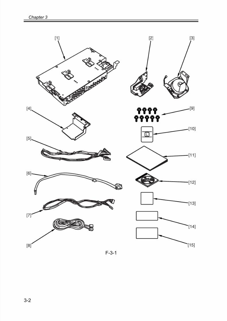
F-3-1
[1] [2] [3]
[4]
[5]
[6]
[7]
[8]
[9]
[10]
[11]
[12]
[13]
[14]
[15]
7/18/2019 Canon Fax Board N1
http://slidepdf.com/reader/full/canon-fax-board-n1 30/125
Chapter 3
3-3
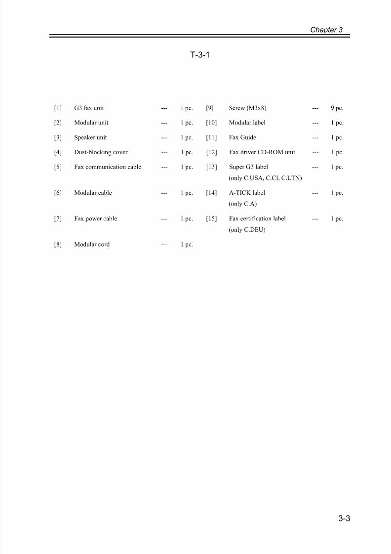
T-3-1
[1] G3 fax unit --- 1 pc. [9] Screw (M3x8) --- 9 pc.
[2] Modular unit --- 1 pc. [10] Modular label --- 1 pc.
[3] Speaker unit --- 1 pc. [11] Fax Guide --- 1 pc.
[4] Dust-blocking cover --- 1 pc. [12] Fax driver CD-ROM unit --- 1 pc.
[5] Fax communication cable --- 1 pc. [13] Super G3 label
(only C.USA, C.CI, C.LTN)
--- 1 pc.
[6] Modular cable --- 1 pc. [14] A-TICK label(only C.A)
--- 1 pc.
[7] Fax power cable --- 1 pc. [15] Fax certification label
(only C.DEU)
--- 1 pc.
[8] Modular cord --- 1 pc.
7/18/2019 Canon Fax Board N1
http://slidepdf.com/reader/full/canon-fax-board-n1 31/125
Chapter 3
3-4
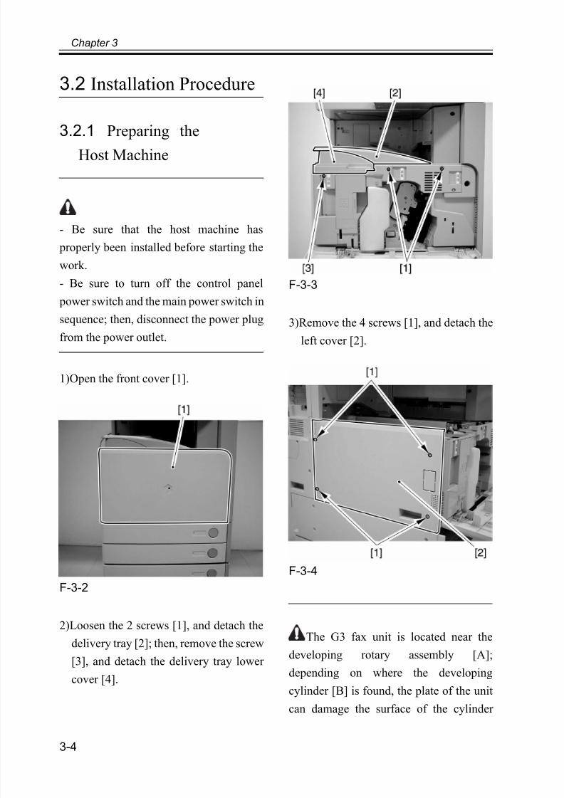
3.2 Installation Procedure
3.2.1 Preparing the
Host Machine
- Be sure that the host machine has
properly been installed before starting the
work.
- Be sure to turn off the control panel
power switch and the main power switch in
sequence; then, disconnect the power plug
from the power outlet.
1)Open the front cover [1].
F-3-2
2)Loosen the 2 screws [1], and detach the
delivery tray [2]; then, remove the screw
[3], and detach the delivery tray lower
cover [4].
F-3-3
3)Remove the 4 screws [1], and detach the
left cover [2].
F-3-4
The G3 fax unit is located near the
developing rotary assembly [A];
depending on where the developing
cylinder [B] is found, the plate of the unit
can damage the surface of the cylinder
7/18/2019 Canon Fax Board N1
http://slidepdf.com/reader/full/canon-fax-board-n1 32/125
Chapter 3
3-5
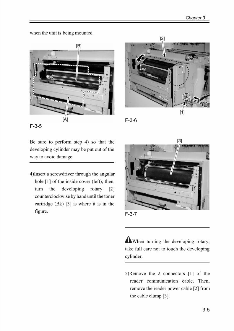
when the unit is being mounted.
F-3-5
Be sure to perform step 4) so that the
developing cylinder may be put out of the
way to avoid damage.
4)Insert a screwdriver through the angular hole [1] of the inside cover (left); then,
turn the developing rotary [2]
counterclockwise by hand until the toner
cartridge (Bk) [3] is where it is in the
figure.
F-3-6
F-3-7
When turning the developing rotary,
take full care not to touch the developing
cylinder.
5)Remove the 2 connectors [1] of the
reader communication cable. Then,
remove the reader power cable [2] fromthe cable clump [3].
7/18/2019 Canon Fax Board N1
http://slidepdf.com/reader/full/canon-fax-board-n1 33/125
Chapter 3
3-6
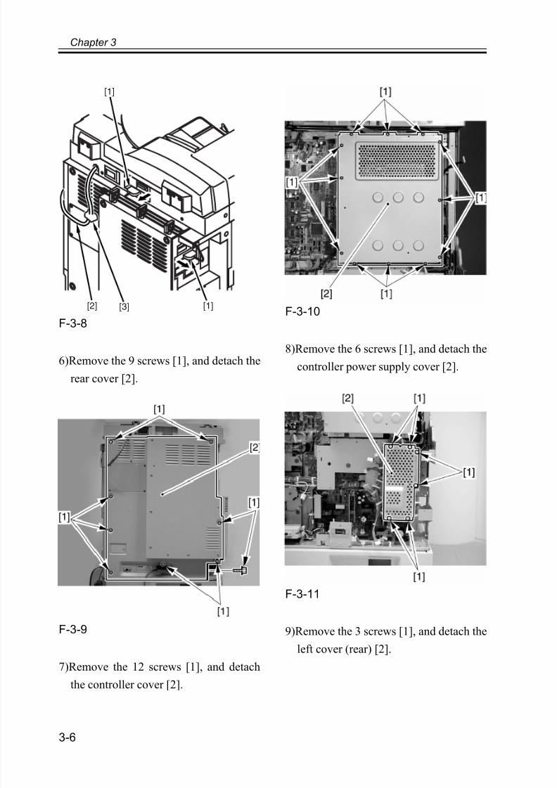
F-3-8
6)Remove the 9 screws [1], and detach the
rear cover [2].
F-3-9
7)Remove the 12 screws [1], and detach
the controller cover [2].
F-3-10
8)Remove the 6 screws [1], and detach the
controller power supply cover [2].
F-3-11
9)Remove the 3 screws [1], and detach the
left cover (rear) [2].
[1]
[1][3][2]
7/18/2019 Canon Fax Board N1
http://slidepdf.com/reader/full/canon-fax-board-n1 34/125
Chapter 3
3-7
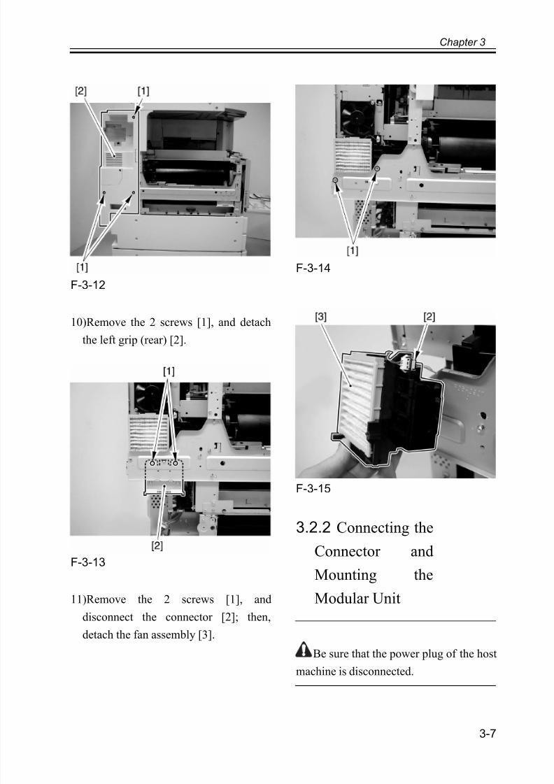
F-3-12
10)Remove the 2 screws [1], and detach
the left grip (rear) [2].
F-3-13
11)Remove the 2 screws [1], and
disconnect the connector [2]; then,
detach the fan assembly [3].
F-3-14
F-3-15
3.2.2 Connecting the
Connector and
Mounting the
Modular Unit
Be sure that the power plug of the host
machine is disconnected.

7/18/2019 Canon Fax Board N1
http://slidepdf.com/reader/full/canon-fax-board-n1 35/125
Chapter 3
3-8
Memo:
The cables that come with the Board are of
3 types: fax communication cable [A],modular cable [B], and fax power cable
[C]. These cables are routed as follows:
F-3-16
1)Fit the foot of the reuse band [1] attached
to one end of each cable (fax
communication cable in photo) in place
on the rear frame; starting from the top,
the fax communication cable [2],
modular cable [3], and fax power cable
[4].
F-3-17
F-3-18
2)Fix the fax communication cable [1] in
place with 7 cable clamps [2].

7/18/2019 Canon Fax Board N1
http://slidepdf.com/reader/full/canon-fax-board-n1 36/125
Chapter 3
3-9
F-3-19
3)Fix the fax communication cable [1] in
place using the edge saddle [2] of the
controller box, and connect it to the
connector (J1210) [3] of the main
controller PCB.
F-3-20
4)Put the controller cover back in place.
5)Secure the modular cable [1] in placeusing 2 cable clamps [2].
F-3-21
6)Connect the modular cable [1] to the
connector [3] of the included modular
unit [2]; then, fix it in place with 2 cable
clamps [4].
F-3-22
7)Mount the modular unit [2] using the
included screw [1].

7/18/2019 Canon Fax Board N1
http://slidepdf.com/reader/full/canon-fax-board-n1 37/125
Chapter 3
3-10
F-3-23
8)Route the fax power cable [1] through
the cable guide [2]; then, fix it in place
using 6 cable clamps [3].
F-3-24
9)Connect the fax power cable [1] to the
connector (J221) [3] on the controller
power supply PCB [2].
F-3-25
10)Put the controller power supply cover
back in place.
3.2.3 Mounting theG3 Fax Unit
1)Hook the 3 points of the bent [2] of the
fax unit [1] in place on the machine left
side plate.

7/18/2019 Canon Fax Board N1
http://slidepdf.com/reader/full/canon-fax-board-n1 38/125
Chapter 3
3-11
F-3-26
2)Connect the 3 cables to the 3 relay
connectors [1] of the G3 fax unit.
F-3-27
Of the 3 cables, use a cable clamp [3]
for the modular cable [2] only.
3)Mount the speaker cable (w/ relay
connector) [1] connected to the G3 fax
unit by pushing it through the hole in the
machine front side plate.
F-3-28
4)Secure the G3 fax unit [2] in place using
the 4 included screws [1].
F-3-29
5)Mount the included dust-blocking cover
[2] suing the 2 included screws [1].

7/18/2019 Canon Fax Board N1
http://slidepdf.com/reader/full/canon-fax-board-n1 39/125
Chapter 3
3-12
F-3-30
3.2.4 Mounting the
Speaker Unit
1)Open the front cover, then the toner
container replacement cover.2)Remove the screw [1], and detach the
waste toner unit retainer [2] and the ITB
waste toner unit [3]; then, remove the 2
screws [4], and detach the inside cover
(middle) [5].
F-3-31
3)Remove the 2 screws [1], and detach the
inside cover (left) [2].
F-3-32
4)Mount the included speaker unit [2]
using the 2 included screws [1]; then,
connect the speaker cable to the relay
connector [3].

7/18/2019 Canon Fax Board N1
http://slidepdf.com/reader/full/canon-fax-board-n1 40/125
Chapter 3
3-13
F-3-33
3.2.5 After the Work
1)Mount the removed fan assembly and the
left grip (rear) back in place.
Ensure that the fan cable is not caught
when attaching the fan assembly.
2)Detach the face cover [2], which is
snapped in place to the left cover (rear)
[1].
F-3-34
Memo:
The detached face cover will no longer be
used.
3)Mount the left cover (rear) [1]; then,
attach the included modular label [2] to
the correct location of the left cover
(rear) [1].
F-3-35
4)Mount the removed covers back in place;
then, close the front cover.
5)Attach the various labels that come with
the board to the machine.
[1]Super G3 label (only C.USA, C.CI,
C.LTN)
[2]Fax certification label (only C.DEU)
[3]A-TICK label (only C.A)
7/18/2019 Canon Fax Board N1
http://slidepdf.com/reader/full/canon-fax-board-n1 41/125
Chapter 3
3-14
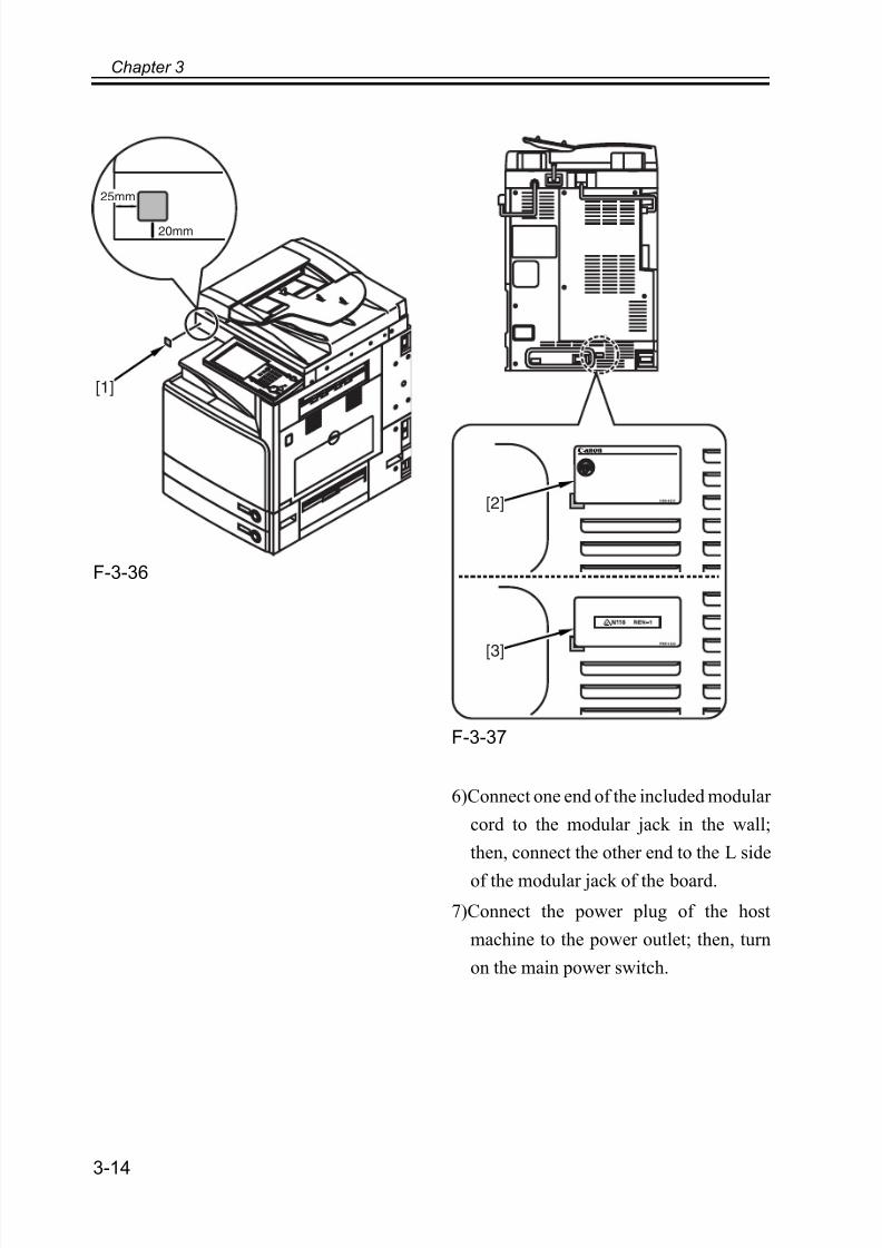
F-3-36
F-3-37
6)Connect one end of the included modular
cord to the modular jack in the wall;
then, connect the other end to the L side
of the modular jack of the board.
7)Connect the power plug of the host
machine to the power outlet; then, turn
on the main power switch.
20mm
25mm
[1]
[2]
[3]

7/18/2019 Canon Fax Board N1
http://slidepdf.com/reader/full/canon-fax-board-n1 42/125
Chapter 3
3-15
3.3 Checking the
Operation
3.3.1 Type Settings
In service mode, select the type of the fax
board as follows: press the Additional
Function key, press the 2 and 8 keys at the
same time, and press the Additional
Function key once again; then, select [fax]
and then [type], and select the countryusing the Up/Down key. At the end, press
the OK key.
3.3.2 Settings
According to Line
Type
Select either dial pulse (20PPS/10PPS) or
push tone to suit the type of telephone line
being used:
Additional Functions key >
Communication Settings > User Settings >
Tel Line Type.
3.3.3 FaxCommunication
Test
Carry out a communications test to see if
the fax functions of the machine operate as
expected:
1)Bring up the Send screen on the control
panel.
2)Send a test original to a party capable of
a communication test, and check to see
if the original is sent normally.
3)Send a text original from the other party,and check to see if the original is sent
normally.

7/18/2019 Canon Fax Board N1
http://slidepdf.com/reader/full/canon-fax-board-n1 43/125

7/18/2019 Canon Fax Board N1
http://slidepdf.com/reader/full/canon-fax-board-n1 44/125
Chapter 4
PartsReplacement
Procedure

7/18/2019 Canon Fax Board N1
http://slidepdf.com/reader/full/canon-fax-board-n1 45/125

7/18/2019 Canon Fax Board N1
http://slidepdf.com/reader/full/canon-fax-board-n1 46/125
Contents
Contents
4.1 Removing from the Host Machine.............................................................4-1
4.1.1 FAX Unit.............................................................................................4-1
4.1.1.1 Removing the Left Cover.............................................................4-1
4.1.1.2 Removing the FAX Unit ..............................................................4-1

7/18/2019 Canon Fax Board N1
http://slidepdf.com/reader/full/canon-fax-board-n1 47/125

7/18/2019 Canon Fax Board N1
http://slidepdf.com/reader/full/canon-fax-board-n1 48/125
Chapter 4
4-1
4.1 Removing from the
Host Machine
4.1.1 FAX Unit
4.1.1.1 Removing the
Left Cover
1) Remove the 4 screws [1], and detach the
left cover [2].
F-4-1
4.1.1.2 Removing the
FAX Unit
1)Disconnect the cable from the 3
connectors [1].
F-4-2
2)Remove the 2 screws [1], and detach the
dust-blocking cover [2].
F-4-3
3)Disconnect the speaker cable from the
relay connector [1].
[2]
[1]
[1]

7/18/2019 Canon Fax Board N1
http://slidepdf.com/reader/full/canon-fax-board-n1 49/125
Chapter 4
4-2
F-4-4
4)Remove the 4 screws [1], and detach the
fax unit [2] from the machine.
F-4-5
7/18/2019 Canon Fax Board N1
http://slidepdf.com/reader/full/canon-fax-board-n1 50/125
Chapter 5
ServiceMode

7/18/2019 Canon Fax Board N1
http://slidepdf.com/reader/full/canon-fax-board-n1 51/125

7/18/2019 Canon Fax Board N1
http://slidepdf.com/reader/full/canon-fax-board-n1 52/125
Contents
Contents
5.1 Outline........................................................................................................5-1
5.1.1 Service Mode Composition.................................................................5-1
5.1.2 Using Service Mode............................................................................5-1
5.1.3 Menu Items..........................................................................................5-4
5.2 Setting of Bit Switch (SSSW)....................................................................5-7
5.2.1 Outline.................................................................................................5-7
5.2.1.1 Bit Switch Composition ...............................................................5-7
5.2.2 SSSW-SW01: Error/Copy Management.............................................5-85.2.2.1 Functional Construction ...............................................................5-8
5.2.2.2 Detailed Discussions of Bit 0.......................................................5-8
5.2.2.3 Detailed Discussions of Bit 1.......................................................5-8
5.2.3 SSSW-SW03: Setting of Echo Measures ...........................................5-9
5.2.3.1 Functional Construction ...............................................................5-9
5.2.3.2 Detailed Discussions of Bit 1.......................................................5-9
5.2.3.3 Detailed Discussions of Bits 4, 5, and 6.....................................5-10
5.2.3.4 Detailed Discussions of Bit 7.....................................................5-115.2.4 SSSW-SW04: Setting of Communication Trouble Measures ..........5-11
5.2.4.1 Functional Construction .............................................................5-11
5.2.4.2 Detailed Discussions of Bit 2.....................................................5-12
5.2.4.3 Detailed Discussions of Bit 3.....................................................5-12
5.2.4.4 Detailed Discussions of Bit 4.....................................................5-12
5.2.5 SSSW-SW05: Setting of Standard Functions (DIS signal)...............5-13
5.2.5.1 Functional Construction .............................................................5-13
5.2.5.2 Detailed Discussions of Bit 1.....................................................5-135.2.5.3 Detailed Discussions of Bit 2.....................................................5-13
5.2.5.4 Detailed Discussions of Bit 3.....................................................5-13
5.2.5.5 Detailed Discussions of Bit 4.....................................................5-14
5.2.6 SSSW-SW12: Setting of Page Timer ...............................................5-14
5.2.6.1 Functional Construction .............................................................5-14
5.2.7 SSSW-SW14: Setting of Inch/Millimeter-base Resolution ..............5-16
5.2.7.1 Functional Construction .............................................................5-16
5.2.7.2 Detailed Discussions of Bit 2.....................................................5-17
7/18/2019 Canon Fax Board N1
http://slidepdf.com/reader/full/canon-fax-board-n1 53/125
5.2.7.3 Detailed Discussions of Bit 4.....................................................5-17
5.2.8 SSSW-SW25: Setting of Report Indication Functions .....................5-17
5.2.8.1 Functional Construction............................................................. 5-17
5.2.8.2 Detailed Discussions of Bit 0.....................................................5-18
5.2.9 SSSW-SW26: Setting of transmission functions.............................. 5-18
5.2.9.1 Functional Construction............................................................. 5-18
5.2.9.2 Detailed Discussions of Bit 2.....................................................5-18
5.2.9.3 Detailed Discussions of Bit 7.....................................................5-18
5.2.10 SSSW-SW28: Procedure Setting for V.8/V.34 ..............................5-19
5.2.10.1 Functional Construction........................................................... 5-19
5.2.10.2 Detailed Discussions of Bit 0................................................... 5-19
5.2.10.3 Detailed Discussions of Bit 1................................................... 5-19
5.2.10.4 Detailed Discussions of Bit 2................................................... 5-19
5.2.10.5 Detailed Discussions of Bit 3................................................... 5-20
5.2.10.6 Detailed Discussions of Bit 4................................................... 5-20
5.2.10.7 Detailed Discussions of Bit 5................................................... 5-20
5.3 Setting of Menu Switch (MENU)............................................................5-21
5.3.1 Menu Switch Composition ............................................................... 5-21
5.3.2 <005: NL Equalizer> ........................................................................ 5-21
5.3.3 <006: Telephone Line Monitor>....................................................... 5-22
5.3.4 <007: ATT Transmission Level> ..................................................... 5-22
5.3.5 <008: V.34 Modulation Speed Upper Limit>...................................5-23
5.3.6 <009: V.34 Data Speed Upper Limit>.............................................. 5-23
5.4 Setting of Numeric Parameter (NUMERIC Param.) ............................... 5-24
5.4.1 Numerical Parameter Composition...................................................5-24
5.4.2 <002: RTN transmission condition (1)><003: RTN transmission
condition (2)><004: RTN transmission condition (3)>.........................5-25
5.4.3 <005: NCC pause length (pre-ID code)>..........................................5-26
5.4.4 <006: NCC pause length (post-ID code)> ........................................ 5-26
5.4.5 <007: pre-pause length at time of ring>............................................5-26
5.4.6 <009: number of comparison digits of source telephone number and target
telephone number>................................................................................. 5-26
5.4.7 <010: line connection identification length> .................................... 5-26
5.4.8 <011: T.30 T1 timer (for reception)> ............................................... 5-26
5.4.9 <013: T.30 EOL timer> ....................................................................5-27
5.4.10 <027: V.21 low-speed flag preamble identification length> .......... 5-27

7/18/2019 Canon Fax Board N1
http://slidepdf.com/reader/full/canon-fax-board-n1 54/125
Contents
5.5 Setting of Destination (TYPE).................................................................5-28
5.5.1 Overview...........................................................................................5-28
5.6 Setting of Printer Functions (PRINTER) .................................................5-29
5.6.1 Setting of Bit Switch (SSSW) ...........................................................5-29
5.6.1.1 SSSW-SW05: Setting of Reduction/Cassette Selection ............5-29
5.6.1.1.1 Functional Construction ......................................................5-29
5.6.1.1.2 Detailed Discussions of Bits 0 and 1...................................5-29
5.6.1.1.3 Detailed Discussions of Bit 7..............................................5-30
5.6.1.2 SSSW-SW06: Reduction Setting ...............................................5-30
5.6.1.2.1 Functional Construction ......................................................5-30
5.6.1.2.2 Detailed Discussions of Bit 5..............................................5-31
5.6.2 Setting of Numeric Parameter (NUMERIC Param.).........................5-31
5.6.2.1 Numerical Parameter Composition............................................5-31
5.6.2.2 <001: printing upon reception of extra-length image> ..............5-32
5.6.2.3 <004: leading edge margin>.......................................................5-32
5.6.2.4 <005: trailing edge margin>.......................................................5-32
5.7 Initialization of Set Value (CLEAR)........................................................5-33
5.7.1 Overview...........................................................................................5-33
5.8 Default Settings........................................................................................5-34
5.8.1 Default Settings.................................................................................5-34
5.9 Test Mode (TEST) ...................................................................................5-45
5.9.1 Outline...............................................................................................5-45
5.9.1.1 Test Mode Construction.............................................................5-45
5.9.2 MODEM Test....................................................................................5-46
5.9.2.1 Relay Test (RELAY-1) ..............................................................5-46
5.9.2.2 Frequency Test (FREQ) .............................................................5-47
5.9.2.3 G3 Signal Transmission Test (G3 Tx) .......................................5-48
5.9.2.4 DTMF Transmission Test ..........................................................5-505.9.2.5 V.34 G3 Signal Transmission Test (V34G3Tx) ........................5-50
5.9.3 Function Test.....................................................................................5-51
5.9.3.1 4800-bps Signal Transmission Test ...........................................5-51
5.10 Service Report (REPORT).....................................................................5-53
5.10.1 System Data List .............................................................................5-53
5.10.2 System Dump List...........................................................................5-54
5.10.3 Error Transmission Report..............................................................5-57

7/18/2019 Canon Fax Board N1
http://slidepdf.com/reader/full/canon-fax-board-n1 55/125
Chapter 5
5-1
5.1 Outline
5.1.1 Service Mode Composition
The Board's service mode consists of the following 10 items (#1 through #10):
#1 SSSW (service soft switch)
Use it to register/set up functions related to basic fax services (e.g., error management, echo
remedies, communication remedies).
#2 MENU (menu switch setting)
Use it to register/setup functions needed at time of installation (e.g., NL equalizer,
transmission level).
#3 NUMERIC Param (numeric parameter settings)
Use it to enter numeric parameters.
#4 NCU (not to be used for service work)
All settings under the item will collectively set in response to the #5 TYPE setting.
#5 TYPE (country settings)
Use it to cause the Board to automatically set data under #4 NCU so that it complies with
the communication requirements of the country in question.
#7 PRINTER (printer functions setup)
Use it to register/set up functions related to basic printer services (e.g., reduction for
received images).
#8 CLEAR data initialization)
Use it to reset various data to initial settings.
#9 TEST
Use it to execute various tests.
#10 REPORT
Use it to print out reports.
5.1.2 Using Service Mode
1)Press the User Mode key " " on the control panel.
2)Press the keys 2 and 8 on the keypad at the same time.
3) Press the User Mode key " " on the control panel once again.

7/18/2019 Canon Fax Board N1
http://slidepdf.com/reader/full/canon-fax-board-n1 56/125
Chapter 5
5-2
The machine will indicate the accessories that are connected to it (e.g., FEEDER, FAX,
BOARD).
Select [FAX] to use service mode items available for the Board.
F-5-1
COPIER: service mode of the host machine.
FEEDER: service mode of the ADF. (*)
FAX: service mode of the fax. (*)
BOARD: service mode of an accessory board. (*)
*: Indicated only if installed.
For instance, in the case of #1 SSSW, the following holds true; key functions and operations
are the same for all screens:
COPIER
FEEDER
BOARD
FAX
SERVICE MODE LEVEL 1

7/18/2019 Canon Fax Board N1
http://slidepdf.com/reader/full/canon-fax-board-n1 57/125
Chapter 5
5-3
F-5-2
- If you want to change 0 to 1 or 1 to 0 on a bit switch, press the desired bit (number) directly.
- If you want to store a change or execute an item, press the OK key.
- Use the keypad to enter a numerical value.
- To return to the previous level of selection, press the Reset key.
If you changed a setting in service mode, be sure to turn off and then on the power
(making sure that you first turn off the control panel switch and then the main power
switch). The settings made in service mode are stored on the hard disk. The settings
associated with the Board are loaded to the G3 fax control PCB only when the main
power is tuned on, thus requiring you to turn it off and then on after making a change.
<1/7> <READY>
ReportSssw Menu Num Ncu Type ISDN Print Clear Test
0 0 0 0 0 0 0 0
1 0 0 0 0 0 0 0
0 0 0 0 0 0 0 0
1 0 0 0 0 0 0 0
0 0 0 0 0 0 0 0
1 0 0 0 0 0 0 0
SW01
SW02
SW03
SW04
SW05
SW06
0 0 0 0 0 0 0 0
1 0 0 0 0 0 0 0
SW07
SW08
OK
Press to accept the current input.Previous Page/Next Page key
7/18/2019 Canon Fax Board N1
http://slidepdf.com/reader/full/canon-fax-board-n1 58/125
Chapter 5
5-4
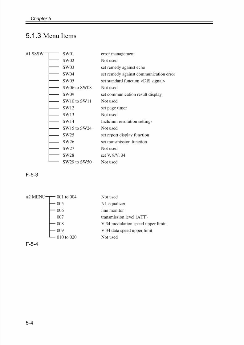
5.1.3 Menu Items
F-5-3
F-5-4
#1 SSSW SW01 error management
SW02 Not used
SW03 set remedy against echo
SW04 set remedy against communication error
SW05 set standard function <DIS signal>
SW06 to SW08 Not used
SW09 set communication result display
SW10 to SW11 Not used
SW12 set page timer
SW13 Not used
SW14 Inch/mm resolution settings
SW15 to SW24 Not used
SW25 set report display function
SW26 set transmission function
SW27 Not used
SW28 set V, 8/V, 34
SW29 to SW50 Not used
#2 MENU 001 to 004 Not used
005 NL equalizer
006 line monitor
007 transmission level (ATT)
008 V.34 modulation speed upper limit
009 V.34 data speed upper limit
010 to 020 Not used

7/18/2019 Canon Fax Board N1
http://slidepdf.com/reader/full/canon-fax-board-n1 59/125
Chapter 5
5-5
F-5-5
F-5-6
#3 NUMERIC 001 not used
002 RTN transmission condition (1)
003 RTN transmission condition (2)
004 RTN transmission condition (3)
005 NCC pause time (before ID code)
006 NCC pause time (after ID code)
007 pre-pulse time at time of call
008 not used
009 number of characters in telephone numbers between
transmitting and receiving parties.
010 line connection identification time
011 T.30 T1 timer (for reception)
012 not used
013 T30. E0L timer
014 to 026 not used
015 hooking detection time
027 preamble detection time for V21 low-speed flag
028 to 080 not used
#7 PRINTER SSSW
NUMERIC Param.
SW01 to SW04
SW05
SW06
SW07 to SW20
not used
reduction/cassette selection
reduction setting
not used
01
02
0304
05
06 to 30
maximum non-image range
not used
not usedleading edge margin
trailing edge margin
not used

7/18/2019 Canon Fax Board N1
http://slidepdf.com/reader/full/canon-fax-board-n1 60/125
Chapter 5
5-6
F-5-7
F-5-8
#8 CLEAR TEL
USSW SW
SRV SW
NCU
SRV DATA
REPORT
ALL
COUNTER
ISDN
#10 CLEAR DATA
DUMP
7/18/2019 Canon Fax Board N1
http://slidepdf.com/reader/full/canon-fax-board-n1 61/125
Chapter 5
5-7
5.2 Setting of Bit Switch (SSSW)
5.2.1 Outline
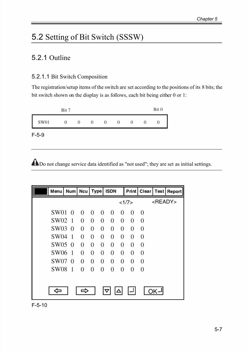
5.2.1.1 Bit Switch Composition
The registration/setup items of the switch are set according to the positions of its 8 bits; the
bit switch shown on the display is as follows, each bit being either 0 or 1:
F-5-9
Do not change service data identified as "not used"; they are set as initial settings.
F-5-10
SW01 0 0 0 0 0 0 0 0
Bit 7 Bit 0
<1/7> <READY>
ReportSssw Menu Num Ncu Type ISDN Print Clear Test
0 0 0 0 0 0 0 0
1 0 0 0 0 0 0 0
0 0 0 0 0 0 0 0
1 0 0 0 0 0 0 0
0 0 0 0 0 0 0 01 0 0 0 0 0 0 0
SW01
SW02
SW03
SW04
SW05SW06
0 0 0 0 0 0 0 0
1 0 0 0 0 0 0 0
SW07
SW08
OK

7/18/2019 Canon Fax Board N1
http://slidepdf.com/reader/full/canon-fax-board-n1 62/125
Chapter 5
5-8
5.2.2 SSSW-SW01: Error/Copy Management
5.2.2.1 Functional Construction
T-5-1
5.2.2.2 Detailed Discussions of Bit 0
Selects whether or not service error codes are output.
When output is selected, service error codes are displayed and in reports.
5.2.2.3 Detailed Discussions of Bit 1
Selects whether or not error dump lists are output.
Bit Function 1 0
0 service error code output not output
1 error dump list output not output
2 not used - -
3 not used - -
4 not used - -
5 not used - -
6 not used - -
7 not used - -

7/18/2019 Canon Fax Board N1
http://slidepdf.com/reader/full/canon-fax-board-n1 63/125
Chapter 5
5-9
5.2.3 SSSW-SW03: Setting of Echo Measures
5.2.3.1 Functional Construction
T-5-2
5.2.3.2 Detailed Discussions of Bit 1
Use it to enable/disable transmission of an echo protect tone for a high-speed transmission
V.29 modem signal (transmission speed at 9600 or 7200 bps).If errors occur frequently at time of transmission because of the condition of the line, select
'transmit' so that a non-modulation carrier will be transmitted as a pre-image transmission
sync signal for about 200 msec.
Memo: Any of the following error codes may be indicated because of the line condition at
time of transmission
##100, ##104, ##281, ##283, ##750, ##755, ##760, ##765
Bit Function 1 0
0 not used - -
1 echo protect tone at high-speed transmission transmit do not
transmit
2 not used - -
3 not used - -
4 transmission mode: international transmission (1) use do not use
5 transmission mode: international transmission (2)
or (3)
use do not use
6 transmission mode international
transmission (3)
international
transmission(2)
7 tonal signal before CED signal transmission transmit do not
transmit

7/18/2019 Canon Fax Board N1
http://slidepdf.com/reader/full/canon-fax-board-n1 64/125
Chapter 5
5-10
5.2.3.3 Detailed Discussions of Bits 4, 5, and 6
Use it to select an appropriate transmission mode: international transmission (1),
international transmission (2), or international transmission (3).
Use the service soft switch or the dial registration function to select the appropriate
transmission mode if errors occur frequently at time of transmission to overseas.
Memo: Any of the following error codes may be indicated because of an echo at time of
transmission
##005, ##100, ##101, ##102, ##104, ##201, ##280, ##281, ##283, ##284, ##750, ##760,
##765, ##774, ##779, ##784, ##794
Using the Dial Recognition Function (user level):
Select 'international transmission (1)' when making an entry in the Address Book. If errors
still occur, select 'international transmission (2)' and then 'international transmission (3)' in
sequence until errors stop. The transmission mode selected using the One-Touch Dial
function or the Speed Dial function will be give priority over the setting made by the service
soft switch.
An international transmission mode may be selected using the keypad if a mode has been
selected using this switch; for settings, see the following table:
T-5-3
International transmission (1): select it to ignore the first DIS signal from the other party.
International transmission (2): select it to transmit a 1850-Hz total signal when transmitting
the DIS signal.
International transmission (3): select it to transmit a 1650-Hz total signal when transmitting
Transmission mode Bit7 Bit6 Bit5 Bit4 Bit3 Bit2 Bit1 Bit0
International
transmission (1)
* 0 0 1 0 0 * 0
Internationaltransmission (2)
* 0 1 0 0 0 * 0
International
transmission (3)
* 1 1 0 0 0 * 0
7/18/2019 Canon Fax Board N1
http://slidepdf.com/reader/full/canon-fax-board-n1 65/125
Chapter 5
5-11
the DIS signal.
5.2.3.4 Detailed Discussions of Bit 7
Use it to enable/disable transmission of a 1080-Hz tonal signal before transmission of the
CED signal.
Select 'transmit' if errors occur frequently because of an echo when reception is from
overseas.
Memo: Any of the following error code may be indicated because of an echo at time of
reception
##005, ##101, ##106, ##107, ##114, ##200, ##201, ##790
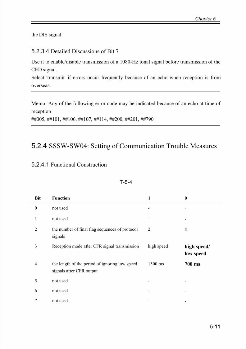
5.2.4 SSSW-SW04: Setting of Communication Trouble Measures
5.2.4.1 Functional Construction
T-5-4
Bit Function 1 0
0 not used - -
1 not used - -
2 the number of final flag sequences of protocol
signals
2 1
3 Reception mode after CFR signal transmission high speed high speed/
low speed
4 the length of the period of ignoring low speed
signals after CFR output
1500 ms 700 ms
5 not used - -
6 not used - -
7 not used - -

7/18/2019 Canon Fax Board N1
http://slidepdf.com/reader/full/canon-fax-board-n1 66/125
Chapter 5
5-12
5.2.4.2 Detailed Discussions of Bit 2
Use it to select the number of last flag sequences for a protocol signal (transmission speed
at 300 bps). Select '2' if the other party fails to receive the protocol signal properly.
Memo: Any of the following error codes may be indicated at time of transmission
##100, ##280, ##281, ##750, ##753, ##754, ##755, ##758, ##759, ##760, ##763 ##764,
##765, ##768, ##769,##770, ##773, ##775, ##778, ##780, ##783, ##785, ##788
5.2.4.3 Detailed Discussions of Bit 3
Use it to select an appropriate reception mode after transmission of the CFR signal.
If errors occur frequently at time of reception because of the condition of the line, select
'high speed' for reception mode and, at the same time, selects 'do not receive' for 'ECM
reception.'
Memo: Any of the following error codes may be indicated at time of reception because of
line condition
##107, ##114, ##201Be sure to change bit 4 before changing this bit; if errors still occur, change this bit.
When 'high speed' is selected, only high-speed signals (images) will be received after
transmission of the CFR signal.
5.2.4.4 Detailed Discussions of Bit 4
Use it to select the time length during which low-speed signals are ignored after transmission of the CFR signal.
If the condition of the line is not good and, therefore, the reception of image signals is
difficult, select '1500 ms.'

7/18/2019 Canon Fax Board N1
http://slidepdf.com/reader/full/canon-fax-board-n1 67/125
Chapter 5
5-13
5.2.5 SSSW-SW05: Setting of Standard Functions (DIS signal)
5.2.5.1 Functional Construction
T-5-5
5.2.5.2 Detailed Discussions of Bit 1
Use it to enable/disable millimeter/inch conversion in sub scanning direction for images
read in text mode.
5.2.5.3 Detailed Discussions of Bit 2
Use it to enable/disable millimeter/inch conversion in sub scanning direction for images
read in text/photo mode while bit 1 is set to '1'.
5.2.5.4 Detailed Discussions of Bit 3
Use it to enable/disable transmission of bit 33 and thereafter (DIS signal).
If 'prohibit' is selected, the Super Fine reception function or Memory Box function
cannot be used for communications from non-Canon machines.
Bit Function 1 0
0 not used - -
1 Conversion from mm to inch (text mode) convert do not convert
2 Conversion from mm to inch (text/photo mode) convert do not convert
3 end DIS signal bits 33 and over prohibit do not
prohibit
4 Recording paper length availability declared in
DIS signal
A4/B4 size any size
5 not used - -
6 not used - -
7 not used - -

7/18/2019 Canon Fax Board N1
http://slidepdf.com/reader/full/canon-fax-board-n1 68/125
Chapter 5
5-14
5.2.5.5 Detailed Discussions of Bit 4
Use it to enable/disable declaration of the use of cut sheets (DIS signal).
For reception of an extra-long original, select 'A4/B4 size' if division is to be by the other
party.
Memo:
Some machines are not designed to divide extra-long originals.
5.2.6 SSSW-SW12: Setting of Page Timer
5.2.6.1 Functional Construction
T-5-6
The machine will stop the ongoing communication if the transmission/reception of a single
Bit Function 1 0
0 Time-out period for one page upon transmission 1 0
1 Time-out period for one page upon transmission 1 0
2 Time-out period for one page upon (HT
transmission)
1 0
3 Time-out period for one page upon (HT
transmission)
1 0
4 Time-out period for one page upon reception 1 0
5 Time-out period for one page upon reception 1 0
6 not used - -
7 Respective page timer settings for transmission
and for reception
enable do not enable

7/18/2019 Canon Fax Board N1
http://slidepdf.com/reader/full/canon-fax-board-n1 69/125
Chapter 5
5-15
original page takes 32 min or more. To use the timer for a purpose other than this function,
refer to the tables that follow, and select an appropriate time length.
When 'do not enable' is selected using bit 7, the time-out length for a single page for all
modes will depend on the setting of bit 0 and bit 1.
T-5-7
T-5-8
T-5-9
Time-Out Length for
Transmission/
Reception
Bit7 Bit6 Bit5 Bit4 Bit3 Bit2 Bit1 Bit0
8 min 0 * * * * * 0 0
16 min 0 * * * * * 0 1
32 min 0 * * * * * 1 0
64 min 0 * * * * * 1 1
Time-Out Length for
Transmission (in text
mode)
Bit7 Bit6 Bit5 Bit4 Bit3 Bit2 Bit1 Bit0
8 min 1 * * * * * 0 0
16 min 1 * * * * * 0 1
32 min 1 * * * * * 1 0
64 min 1 * * * * * 1 1
Time-Out Length for
Transmission (image
mode other than text
mode)
Bit7 Bit6 Bit5 Bit4 Bit3 Bit2 Bit1 Bit0
8 min 1 * * * 0 0 * *
16 min 1 * * * 0 1 * *

7/18/2019 Canon Fax Board N1
http://slidepdf.com/reader/full/canon-fax-board-n1 70/125
Chapter 5
5-16
T-5-10
5.2.7 SSSW-SW14: Setting of Inch/Millimeter-base Resolution
5.2.7.1 Functional Construction
T-5-11
32 min 1 * * * 1 0 * *
64 min 1 * * * 1 1 * *
Time-Out Length for
Reception
Bit7 Bit6 Bit5 Bit4 Bit3 Bit2 Bit1 Bit0
8 min 1 * 0 0 * * * *
16 min 1 * 0 1 * * * *
32 min 1 * 1 0 * * * *
64 min 1 * 1 1 * * * *
Bit Function 1 0
0 not used - -
1 not used - -
2 direction of scanning for inch/mm conversion both main and
sub scanning
directions
sub scanning
direction only
3 not used - -
4 inch-configuration resolution declaration declare do not declare
5 not used - -
Time-Out Length for
Transmission (image
mode other than text
mode)
Bit7 Bit6 Bit5 Bit4 Bit3 Bit2 Bit1 Bit0
7/18/2019 Canon Fax Board N1
http://slidepdf.com/reader/full/canon-fax-board-n1 71/125
Chapter 5
5-17
5.2.7.2 Detailed Discussions of Bit 2
Use it to specify whether to convert or not convert an inch-configuration resolution into a
millimeter-configuration resolution for image read in G3 transmission: either in sub
scanning direction only or in both main and sub scanning directions. The setting is valid
only when bit 1 of SW05 of #1 SSSW is set to '1'.
5.2.7.3 Detailed Discussions of Bit 4
Use it to specify whether to declare or not declare an inch-configuration resolution to the
other machine for G3 communication: if 'declare' is selected, the machine will indicate that
it reads and records at an inch-configuration resolution using the DIS, DCS, or DTC signal.
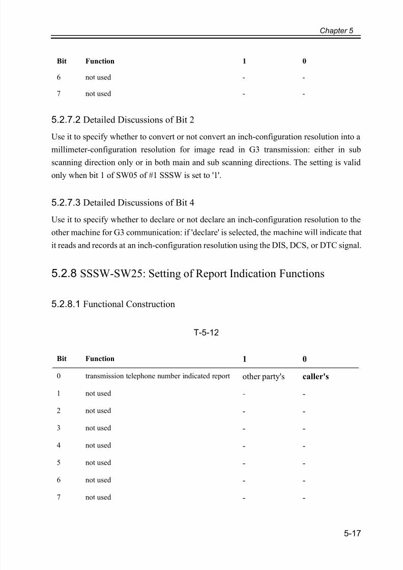
5.2.8 SSSW-SW25: Setting of Report Indication Functions
5.2.8.1 Functional Construction
T-5-12
6 not used - -
7 not used - -
Bit Function 1 0
0 transmission telephone number indicated report other party's caller's
1 not used - -
2 not used - -
3 not used - -
4 not used - -
5 not used - -
6 not used - -
7 not used - -
Bit Function 1 0
7/18/2019 Canon Fax Board N1
http://slidepdf.com/reader/full/canon-fax-board-n1 72/125
Chapter 5
5-18
5.2.8.2 Detailed Discussions of Bit 0
Use it to select the transmission telephone number indicated on the report at the end of
transmission.
caller's number: indicates the telephone number of the caller on the report.
number of other party: indicates the telephone number (CSI signal data) sent from the other
part on the report.
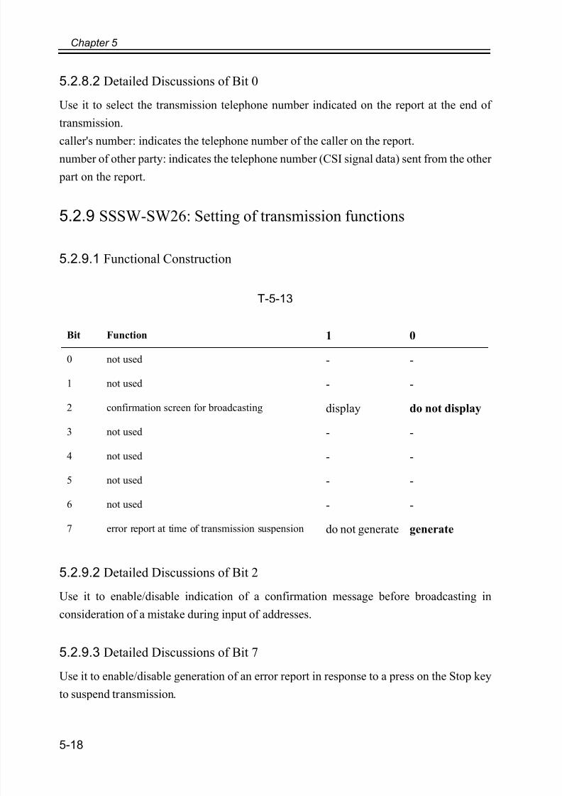
5.2.9 SSSW-SW26: Setting of transmission functions
5.2.9.1 Functional Construction
T-5-13
5.2.9.2 Detailed Discussions of Bit 2
Use it to enable/disable indication of a confirmation message before broadcasting in
consideration of a mistake during input of addresses.
5.2.9.3 Detailed Discussions of Bit 7
Use it to enable/disable generation of an error report in response to a press on the Stop key
to suspend transmission.
Bit Function 1 0
0 not used - -
1 not used - -
2 confirmation screen for broadcasting display do not display
3 not used - -
4 not used - -
5 not used - -
6 not used - -
7 error report at time of transmission suspension do not generate generate
7/18/2019 Canon Fax Board N1
http://slidepdf.com/reader/full/canon-fax-board-n1 73/125
Chapter 5
5-19
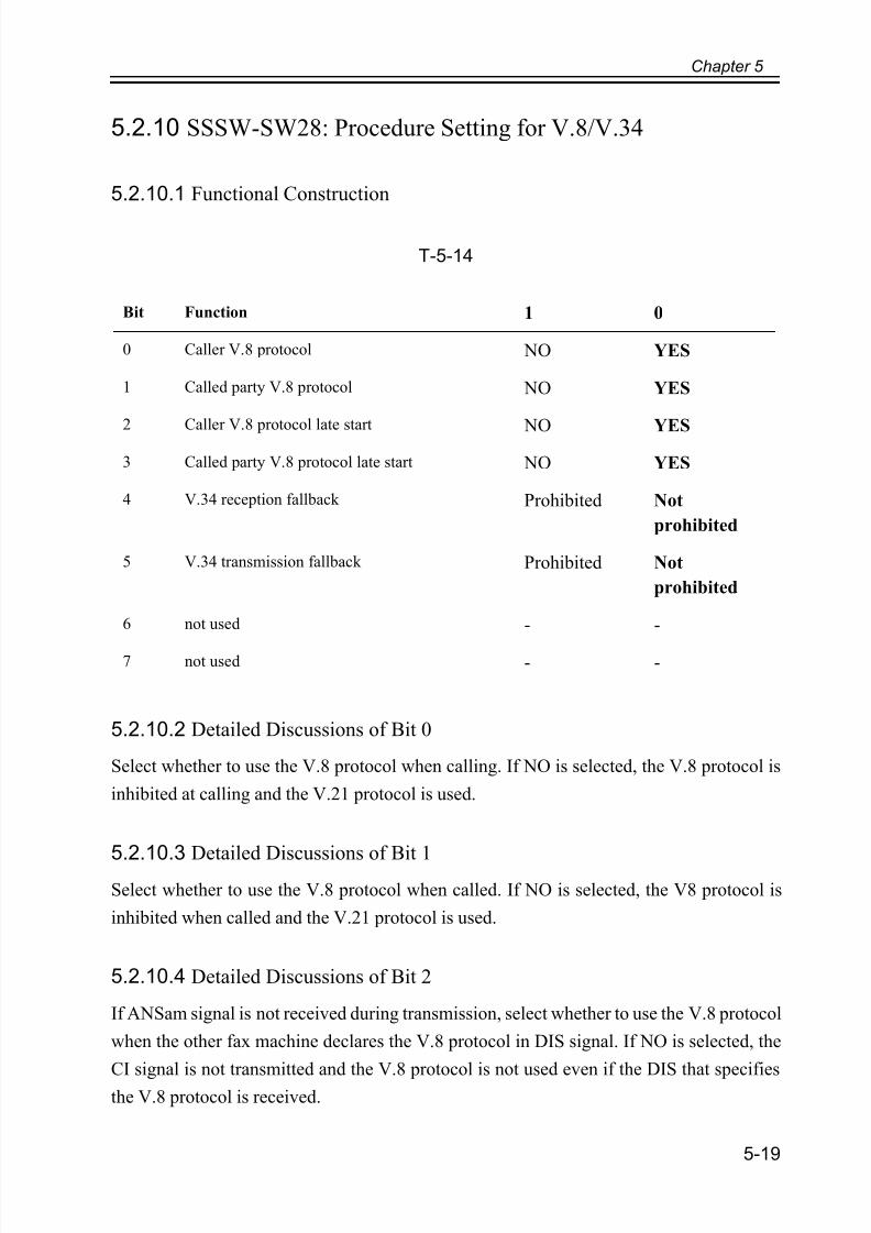
5.2.10 SSSW-SW28: Procedure Setting for V.8/V.34
5.2.10.1 Functional Construction
T-5-14
5.2.10.2 Detailed Discussions of Bit 0
Select whether to use the V.8 protocol when calling. If NO is selected, the V.8 protocol is
inhibited at calling and the V.21 protocol is used.
5.2.10.3 Detailed Discussions of Bit 1Select whether to use the V.8 protocol when called. If NO is selected, the V8 protocol is
inhibited when called and the V.21 protocol is used.
5.2.10.4 Detailed Discussions of Bit 2
If ANSam signal is not received during transmission, select whether to use the V.8 protocol
when the other fax machine declares the V.8 protocol in DIS signal. If NO is selected, the
CI signal is not transmitted and the V.8 protocol is not used even if the DIS that specifies
the V.8 protocol is received.
Bit Function 1 0
0 Caller V.8 protocol NO YES
1 Called party V.8 protocol NO YES
2 Caller V.8 protocol late start NO YES
3 Called party V.8 protocol late start NO YES
4 V.34 reception fallback Prohibited Not
prohibited
5 V.34 transmission fallback Prohibited Not
prohibited
6 not used - -
7 not used - -
7/18/2019 Canon Fax Board N1
http://slidepdf.com/reader/full/canon-fax-board-n1 74/125
Chapter 5
5-20
5.2.10.5 Detailed Discussions of Bit 3
Select whether to declare the V.8 protocol in DIS signal for reception. If NO is selected, the
V.8 protocol cannot be used because it is not declared in DIS signal.
5.2.10.6 Detailed Discussions of Bit 4
Select whether the receiver falls back during V.34 reception. If 'Prohibit' is selected, the
receiver does not fall back.
5.2.10.7 Detailed Discussions of Bit 5
Select whether the transmitter falls beck during V.34 transmission. If 'Prohibit' is selected,
teh transmitter does not fall back.

7/18/2019 Canon Fax Board N1
http://slidepdf.com/reader/full/canon-fax-board-n1 75/125
Chapter 5
5-21
5.3 Setting of Menu Switch (MENU)
5.3.1 Menu Switch Composition
F-5-11
T-5-15
5.3.2 <005: NL Equalizer>
Use it to enable-disable the NL equalizer.
If errors occur often during communication because of the condition of the line, enable
No. Function Range of settings
005 NL equalizer 1: ON, 0: OFF
006 telephone line monitor from 0 to 3
007 transmission level (ATT) from 8 to 15 (ex: 15= -15 dBm)
008 V.34 modulation speed
upper limit
0:3429, 1:3200, 2:3000, 3:2800, 4:2743, 5:2400
009 V34 data speed upper limit from 0 to 13
<1/3> <READY>
ReportSssw Menu Num Ncu Type ISDN Print Clear Test
OK
xxxxx001
xxxxx002
xxxxx003
xxxxx004xxxxx
xxxxx
xxxxx
005
006
007
008
xxxxx
7/18/2019 Canon Fax Board N1
http://slidepdf.com/reader/full/canon-fax-board-n1 76/125
Chapter 5
5-22
(ON) the NL equalizer.
Memo:
Any of the following error codes may be indicated at time of transmission because of theline condition
##100, ##101, ##102, ##104, ##201, ##281, ##282, ##283,
##750, ##755, ##765, ##774, ##779, ##784, ##789
Any of the following error codes may be indicated at time of transmission because of the
line condition
##103, ##107, ##114, ##201, ##790, ##793
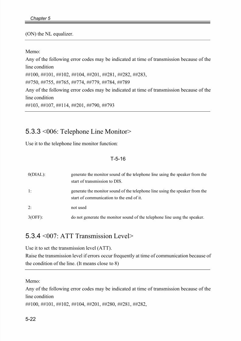
5.3.3 <006: Telephone Line Monitor>
Use it to the telephone line monitor function:
T-5-16
5.3.4 <007: ATT Transmission Level>Use it to set the transmission level (ATT).
Raise the transmission level if errors occur frequently at time of communication because of
the condition of the line. (It means close to 8)
Memo:
Any of the following error codes may be indicated at time of transmission because of the
line condition##100, ##101, ##102, ##104, ##201, ##280, ##281, ##282,
0(DIAL): generate the monitor sound of the telephone line using the speaker from the
start of transmission to DIS.
1: generate the monitor sound of the telephone line using the speaker from the
start of communication to the end of it.
2: not used
3(OFF): do not generate the monitor sound of the telephone line usng the speaker.

7/18/2019 Canon Fax Board N1
http://slidepdf.com/reader/full/canon-fax-board-n1 77/125
Chapter 5
5-23
##283, ##284, ##750, ##752, ##754, ##755, ##757, ##759,
##760, ##762, ##764, ##765, ##767, ##769, ##770, ##772,
##774, ##775, ##777, ##779, ##780, ##782, ##784, ##785,
##787, ##789
Any of the following error codes may be indicated at time of reception because of the line
condition
##103, ##106, ##107, ##201, ##793
5.3.5 <008: V.34 Modulation Speed Upper Limit>
Use it to set an upper limit to the modulation speed (baud rate) for the V.34 primary channel.
5.3.6 <009: V.34 Data Speed Upper Limit>
Use to set an upper limit to the data transmission speed for the V.34 primary channel
between 2.4K and 33.6K bps in increments of 2400 bps. (0: 2.4K to 13: 33.6K bps).

7/18/2019 Canon Fax Board N1
http://slidepdf.com/reader/full/canon-fax-board-n1 78/125
Chapter 5
5-24
5.4 Setting of Numeric Parameter (NUMERIC Param.)
5.4.1 Numerical Parameter Composition
F-5-12
T-5-17
No. Function Range of settings Initial setting
002 RTN transmission condition (1) 1% to 99% 10
003 RTN transmission condition (2) 2 to 99 times 15
004 RTN transmission condition (3) 1 to 99 lines 12
005 NCC pause time (before ID code) 1 to 60 sec 4
006 NCC pause time (after ID code) 1 to 60 sec 4
007 pre-pause time at time of placing call 0 to 9999 (x10ms) 0
009 number of characters in telephone numbers between
transmitting and
receiving parties
0 to 20 characters 0
010 line connection identification time 0 to 9999 (10ms) 5500
<1/10> <READY>
ReportSssw Menu Num Ncu Type ISDN Print Clear Test
OK
xxxxx001
xxxxx002
xxxxx003
xxxxx004xxxxx005
xxxxx006
xxxxx007
xxxxx008
7/18/2019 Canon Fax Board N1
http://slidepdf.com/reader/full/canon-fax-board-n1 79/125
Chapter 5
5-25
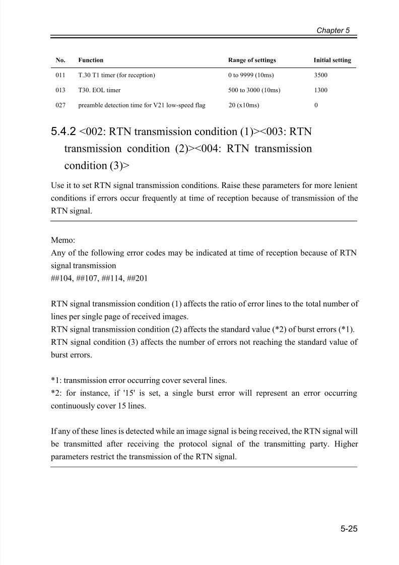
5.4.2 <002: RTN transmission condition (1)><003: RTN
transmission condition (2)><004: RTN transmission
condition (3)>
Use it to set RTN signal transmission conditions. Raise these parameters for more lenient
conditions if errors occur frequently at time of reception because of transmission of theRTN signal.
Memo:
Any of the following error codes may be indicated at time of reception because of RTN
signal transmission
##104, ##107, ##114, ##201
RTN signal transmission condition (1) affects the ratio of error lines to the total number of
lines per single page of received images.
RTN signal transmission condition (2) affects the standard value (*2) of burst errors (*1).
RTN signal condition (3) affects the number of errors not reaching the standard value of
burst errors.
*1: transmission error occurring cover several lines.
*2: for instance, if '15' is set, a single burst error will represent an error occurringcontinuously cover 15 lines.
If any of these lines is detected while an image signal is being received, the RTN signal will
be transmitted after receiving the protocol signal of the transmitting party. Higher
parameters restrict the transmission of the RTN signal.
011 T.30 T1 timer (for reception) 0 to 9999 (10ms) 3500
013 T30. EOL timer 500 to 3000 (10ms) 1300
027 preamble detection time for V21 low-speed flag 20 (x10ms) 0
No. Function Range of settings Initial setting

7/18/2019 Canon Fax Board N1
http://slidepdf.com/reader/full/canon-fax-board-n1 80/125
Chapter 5
5-26
5.4.3 <005: NCC pause length (pre-ID code)>
Use it to set the length of the pause automatically entered between access code and ID code
when the NCC (New Common Carrier) line is used for dialing.
5.4.4 <006: NCC pause length (post-ID code)>
Use it to set the length of the pause automatically entered between ID code and telephone
number of the other party when the NCC (New Common Carrier) line is used for dialing.
5.4.5 <007: pre-pause length at time of ring>
Use it to set the length of the pause used when placing a call.
5.4.6 <009: number of comparison digits of source
telephone number and target telephone number>
Use it to set the number of TSI comparison characters (lower $ characters) for a check on
telephone numbers.
5.4.7 <010: line connection identification length>
Use it to set the time for identifying the line connection. Raise this parameter if errors occur
frequently at time of communication because of the condition of the line.
Memo: Any of the following error codes may be indicated because of the condition of the
line
##005, ##018The line condition identification time is between when the dial signal is transmitted and
when the line condition is cut for the transmitting party, while it is between when the DIS
signal is transmitted and when the line is cut for the receiving party.
5.4.8 <011: T.30 T1 timer (for reception)>
Set it so that the T1 time may be varied. (The regulations governing the T1 timer vary fromcountry to country (PTT)).

7/18/2019 Canon Fax Board N1
http://slidepdf.com/reader/full/canon-fax-board-n1 81/125
Chapter 5
5-27
5.4.9 <013: T.30 EOL timer>
Set it so that the 1-line transmission time is longer for reception to prevent reception errors
caused by a long data length per line (e.g., computer FAX).
5.4.10 <027: V.21 low-speed flag preamble identification
length>
Use it to detect the time of detection after which command analysis is started after detecting
V.21 low-speed command preambles continuously for a specific period of time.

7/18/2019 Canon Fax Board N1
http://slidepdf.com/reader/full/canon-fax-board-n1 82/125
Chapter 5
5-28
5.5 Setting of Destination (TYPE)
5.5.1 Overview
When the type shown on the display is set, all the service data is set to match each country
domestic telecommunication standards.
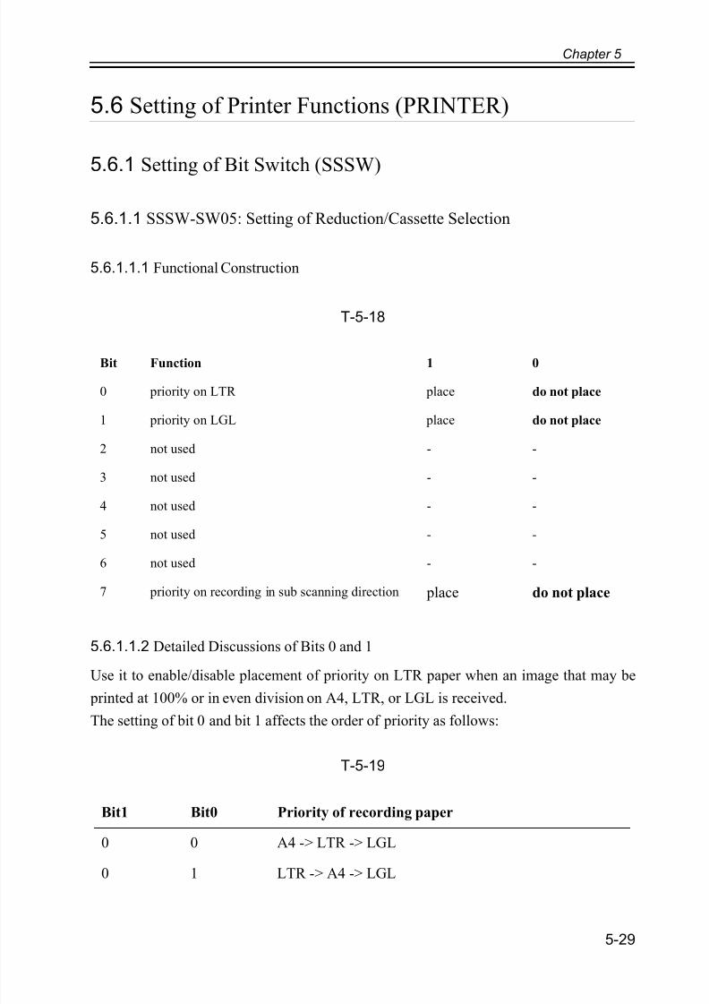
7/18/2019 Canon Fax Board N1
http://slidepdf.com/reader/full/canon-fax-board-n1 83/125
Chapter 5
5-29
5.6 Setting of Printer Functions (PRINTER)
5.6.1 Setting of Bit Switch (SSSW)
5.6.1.1 SSSW-SW05: Setting of Reduction/Cassette Selection
5.6.1.1.1 Functional Construction
T-5-18
5.6.1.1.2 Detailed Discussions of Bits 0 and 1
Use it to enable/disable placement of priority on LTR paper when an image that may be
printed at 100% or in even division on A4, LTR, or LGL is received.The setting of bit 0 and bit 1 affects the order of priority as follows:
T-5-19
Bit Function 1 0
0 priority on LTR place do not place
1 priority on LGL place do not place
2 not used - -
3 not used - -
4 not used - -
5 not used - -
6 not used - -
7 priority on recording in sub scanning direction place do not place
Bit1 Bit0 Priority of recording paper
0 0 A4 -> LTR -> LGL
0 1 LTR -> A4 -> LGL
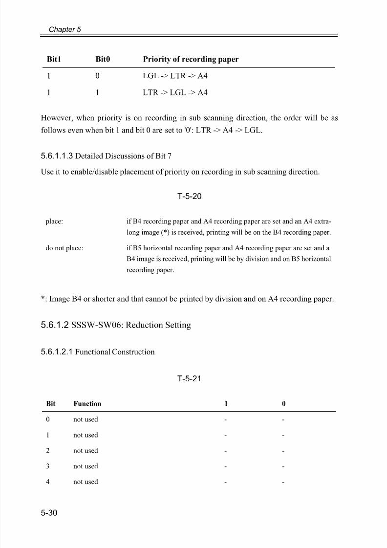
7/18/2019 Canon Fax Board N1
http://slidepdf.com/reader/full/canon-fax-board-n1 84/125
Chapter 5
5-30
However, when priority is on recording in sub scanning direction, the order will be as
follows even when bit 1 and bit 0 are set to '0': LTR -> A4 -> LGL.
5.6.1.1.3 Detailed Discussions of Bit 7
Use it to enable/disable placement of priority on recording in sub scanning direction.
T-5-20
*: Image B4 or shorter and that cannot be printed by division and on A4 recording paper.
5.6.1.2 SSSW-SW06: Reduction Setting
5.6.1.2.1 Functional Construction
T-5-21
1 0 LGL -> LTR -> A4
1 1 LTR -> LGL -> A4
place: if B4 recording paper and A4 recording paper are set and an A4 extra-
long image (*) is received, printing will be on the B4 recording paper.
do not place: if B5 horizontal recording paper and A4 recording paper are set and a
B4 image is received, printing will be by division and on B5 horizontal
recording paper.
Bit Function 1 0
0 not used - -
1 not used - -
2 not used - -
3 not used - -
4 not used - -
Bit1 Bit0 Priority of recording paper

7/18/2019 Canon Fax Board N1
http://slidepdf.com/reader/full/canon-fax-board-n1 85/125
Chapter 5
5-31
5.6.1.2.2 Detailed Discussions of Bit 5
Use it to force printing on B5 by reduction (of A4 received image). Setting this bit will cause
all A4 reports to be printed in B5 by division.
5.6.2 Setting of Numeric Parameter (NUMERIC Param.)
5.6.2.1 Numerical Parameter Composition
F-5-13
T-5-22
5 reduced printing from A4 to B5 enable disable
6 not used - -
7 not used - -
No. Function Setting range Initial
setting
Unit
Bit Function 1 0
<1/4> <READY><NUM>
ReportSssw Menu Num Ncu Type ISDN Print Clear Test
OK
xxxxx001
xxxxx002
xxxxx003
xxxxx004
xxxxx005
xxxxx006
xxxxx007
xxxxx008

7/18/2019 Canon Fax Board N1
http://slidepdf.com/reader/full/canon-fax-board-n1 86/125
Chapter 5
5-32
5.6.2.2 <001: printing upon reception of extra-length image>
Use it to set the range of the image to be removed from when printing an extra-length
received image.
Lower the parameter to decrease the range if the trailing edge of the received image must
be retained (as when it is longer than the effective recording length).
5.6.2.3 <004: leading edge margin>
Use it to set the leading-edge margin for the effective recording length.
5.6.2.4 <005: trailing edge margin>
Use it to set the trailing-edge margin for the effective recording length.
01 Missing areas of printing image when
receiving image with longer length than
standard
0 to 9999 12 1mm
04 Leading edge blank area 0 to 9999 3 1mm
05 Trailing edge blank area 0 to 9999 3 1mm
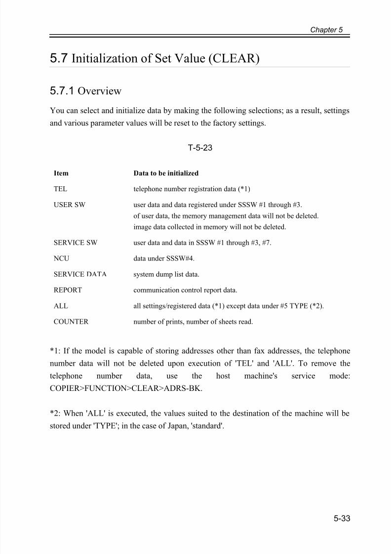
7/18/2019 Canon Fax Board N1
http://slidepdf.com/reader/full/canon-fax-board-n1 87/125
Chapter 5
5-33
5.7 Initialization of Set Value (CLEAR)
5.7.1 Overview
You can select and initialize data by making the following selections; as a result, settings
and various parameter values will be reset to the factory settings.
T-5-23
*1: If the model is capable of storing addresses other than fax addresses, the telephone
number data will not be deleted upon execution of 'TEL' and 'ALL'. To remove the
telephone number data, use the host machine's service mode:
COPIER>FUNCTION>CLEAR>ADRS-BK.
*2: When 'ALL' is executed, the values suited to the destination of the machine will be
stored under 'TYPE'; in the case of Japan, 'standard'.
Item Data to be initialized
TEL telephone number registration data (*1)
USER SW user data and data registered under SSSW #1 through #3.
of user data, the memory management data will not be deleted.
image data collected in memory will not be deleted.
SERVICE SW user data and data in SSSW #1 through #3, #7.
NCU data under SSSW#4.
SERVICE DATA system dump list data.
REPORT communication control report data.
ALL all settings/registered data (*1) except data under #5 TYPE (*2).
COUNTER number of prints, number of sheets read.
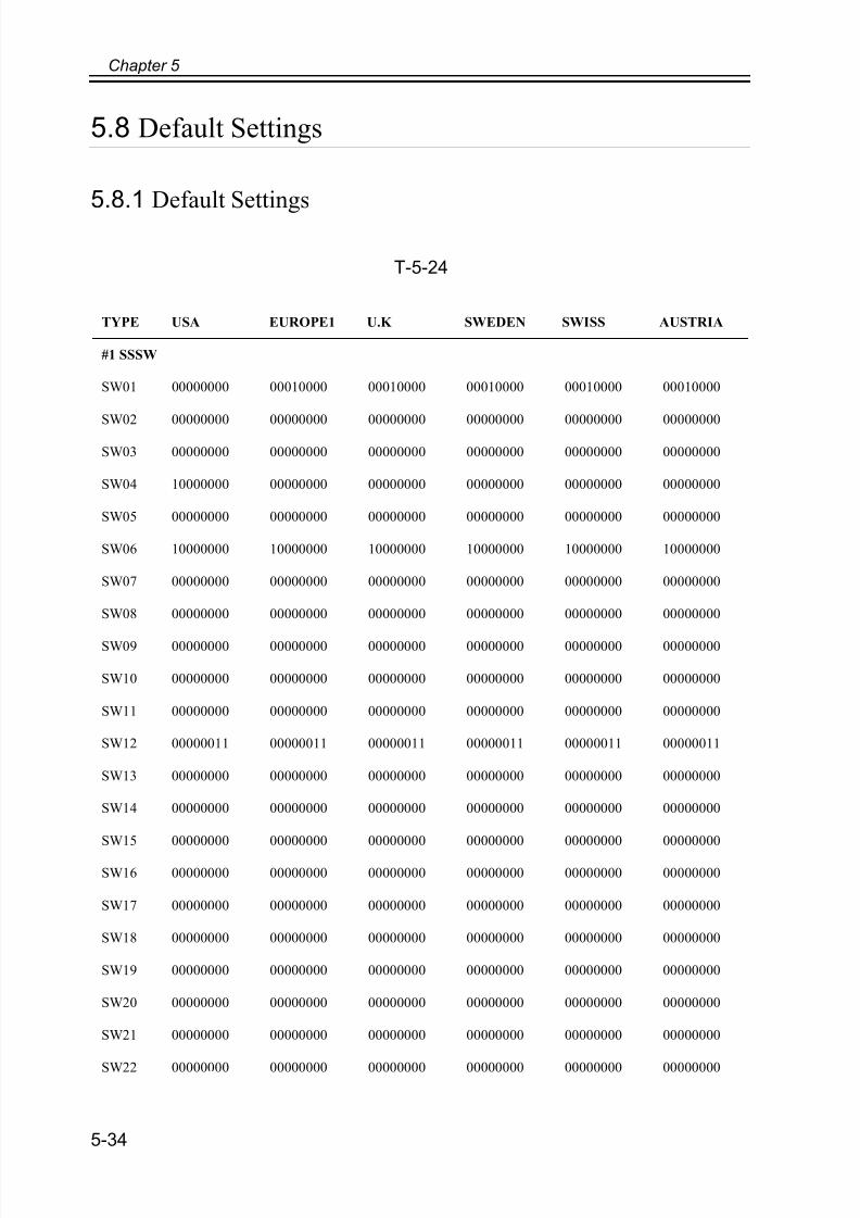
7/18/2019 Canon Fax Board N1
http://slidepdf.com/reader/full/canon-fax-board-n1 88/125
Chapter 5
5-34
5.8 Default Settings
5.8.1 Default Settings
T-5-24
TYPE USA EUROPE1 U.K SWEDEN SWISS AUSTRIA
#1 SSSW
SW01 00000000 00010000 00010000 00010000 00010000 00010000
SW02 00000000 00000000 00000000 00000000 00000000 00000000
SW03 00000000 00000000 00000000 00000000 00000000 00000000
SW04 10000000 00000000 00000000 00000000 00000000 00000000
SW05 00000000 00000000 00000000 00000000 00000000 00000000
SW06 10000000 10000000 10000000 10000000 10000000 10000000
SW07 00000000 00000000 00000000 00000000 00000000 00000000
SW08 00000000 00000000 00000000 00000000 00000000 00000000
SW09 00000000 00000000 00000000 00000000 00000000 00000000
SW10 00000000 00000000 00000000 00000000 00000000 00000000
SW11 00000000 00000000 00000000 00000000 00000000 00000000
SW12 00000011 00000011 00000011 00000011 00000011 00000011
SW13 00000000 00000000 00000000 00000000 00000000 00000000
SW14 00000000 00000000 00000000 00000000 00000000 00000000
SW15 00000000 00000000 00000000 00000000 00000000 00000000
SW16 00000000 00000000 00000000 00000000 00000000 00000000
SW17 00000000 00000000 00000000 00000000 00000000 00000000
SW18 00000000 00000000 00000000 00000000 00000000 00000000
SW19 00000000 00000000 00000000 00000000 00000000 00000000
SW20 00000000 00000000 00000000 00000000 00000000 00000000
SW21 00000000 00000000 00000000 00000000 00000000 00000000
SW22 00000000 00000000 00000000 00000000 00000000 00000000
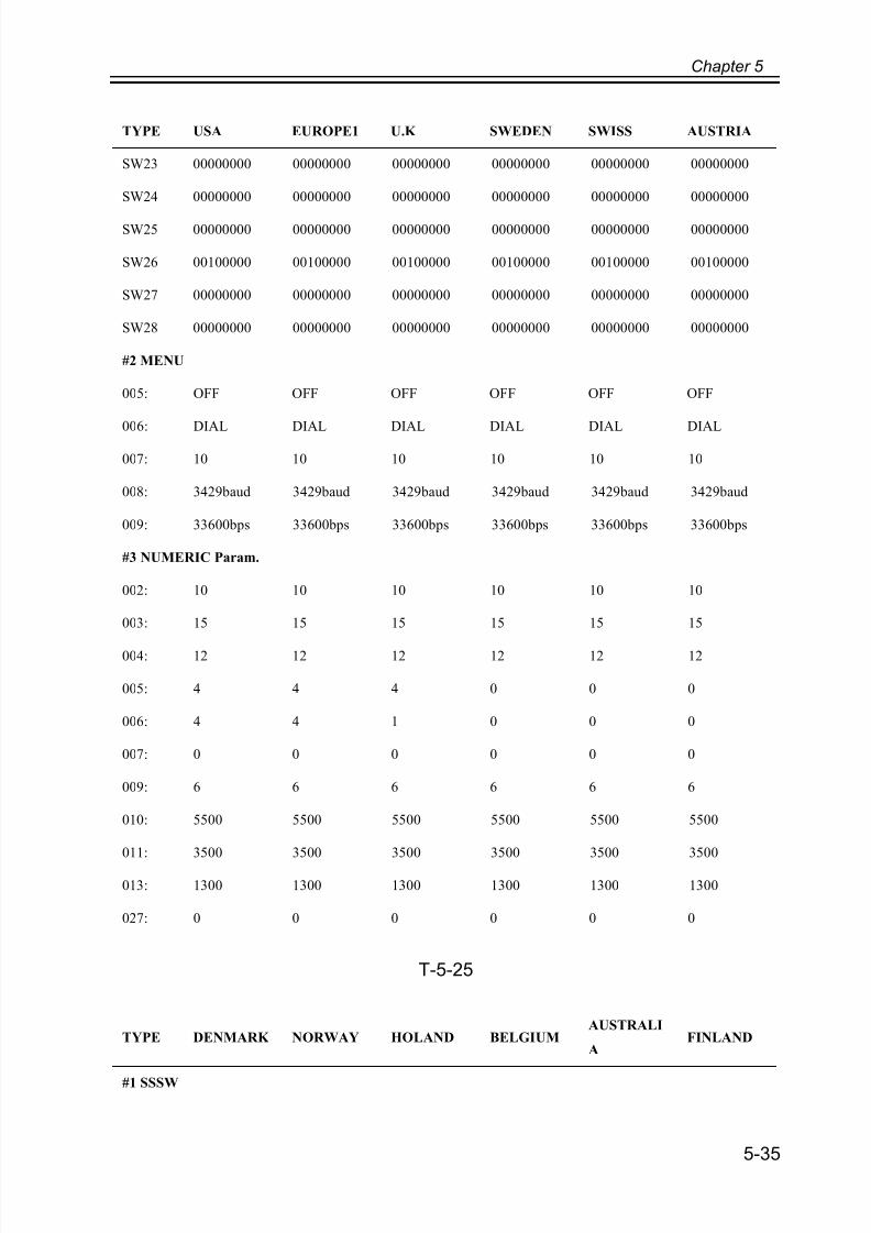
7/18/2019 Canon Fax Board N1
http://slidepdf.com/reader/full/canon-fax-board-n1 89/125
Chapter 5
5-35
T-5-25
SW23 00000000 00000000 00000000 00000000 00000000 00000000
SW24 00000000 00000000 00000000 00000000 00000000 00000000
SW25 00000000 00000000 00000000 00000000 00000000 00000000
SW26 00100000 00100000 00100000 00100000 00100000 00100000
SW27 00000000 00000000 00000000 00000000 00000000 00000000
SW28 00000000 00000000 00000000 00000000 00000000 00000000
#2 MENU
005: OFF OFF OFF OFF OFF OFF
006: DIAL DIAL DIAL DIAL DIAL DIAL
007: 10 10 10 10 10 10
008: 3429baud 3429baud 3429baud 3429baud 3429baud 3429baud
009: 33600bps 33600bps 33600bps 33600bps 33600bps 33600bps
#3 NUMERIC Param.
002: 10 10 10 10 10 10
003: 15 15 15 15 15 15
004: 12 12 12 12 12 12
005: 4 4 4 0 0 0
006: 4 4 1 0 0 0
007: 0 0 0 0 0 0
009: 6 6 6 6 6 6
010: 5500 5500 5500 5500 5500 5500
011: 3500 3500 3500 3500 3500 3500
013: 1300 1300 1300 1300 1300 1300
027: 0 0 0 0 0 0
TYPE DENMARK NORWAY HOLAND BELGIUMAUSTRALI
AFINLAND
#1 SSSW
TYPE USA EUROPE1 U.K SWEDEN SWISS AUSTRIA
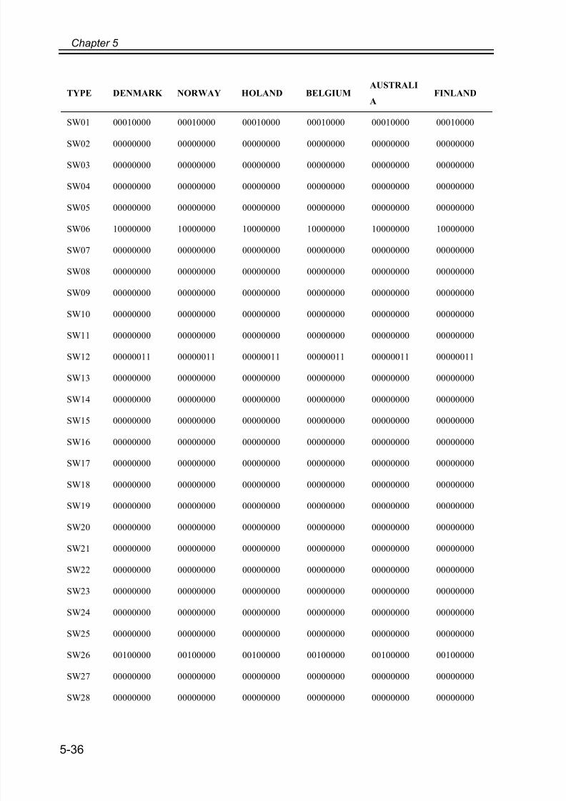
7/18/2019 Canon Fax Board N1
http://slidepdf.com/reader/full/canon-fax-board-n1 90/125
Chapter 5
5-36
SW01 00010000 00010000 00010000 00010000 00010000 00010000
SW02 00000000 00000000 00000000 00000000 00000000 00000000
SW03 00000000 00000000 00000000 00000000 00000000 00000000
SW04 00000000 00000000 00000000 00000000 00000000 00000000
SW05 00000000 00000000 00000000 00000000 00000000 00000000
SW06 10000000 10000000 10000000 10000000 10000000 10000000
SW07 00000000 00000000 00000000 00000000 00000000 00000000
SW08 00000000 00000000 00000000 00000000 00000000 00000000
SW09 00000000 00000000 00000000 00000000 00000000 00000000
SW10 00000000 00000000 00000000 00000000 00000000 00000000
SW11 00000000 00000000 00000000 00000000 00000000 00000000
SW12 00000011 00000011 00000011 00000011 00000011 00000011
SW13 00000000 00000000 00000000 00000000 00000000 00000000
SW14 00000000 00000000 00000000 00000000 00000000 00000000
SW15 00000000 00000000 00000000 00000000 00000000 00000000
SW16 00000000 00000000 00000000 00000000 00000000 00000000
SW17 00000000 00000000 00000000 00000000 00000000 00000000
SW18 00000000 00000000 00000000 00000000 00000000 00000000
SW19 00000000 00000000 00000000 00000000 00000000 00000000
SW20 00000000 00000000 00000000 00000000 00000000 00000000
SW21 00000000 00000000 00000000 00000000 00000000 00000000
SW22 00000000 00000000 00000000 00000000 00000000 00000000
SW23 00000000 00000000 00000000 00000000 00000000 00000000
SW24 00000000 00000000 00000000 00000000 00000000 00000000
SW25 00000000 00000000 00000000 00000000 00000000 00000000
SW26 00100000 00100000 00100000 00100000 00100000 00100000
SW27 00000000 00000000 00000000 00000000 00000000 00000000
SW28 00000000 00000000 00000000 00000000 00000000 00000000
TYPE DENMARK NORWAY HOLAND BELGIUMAUSTRALI
AFINLAND
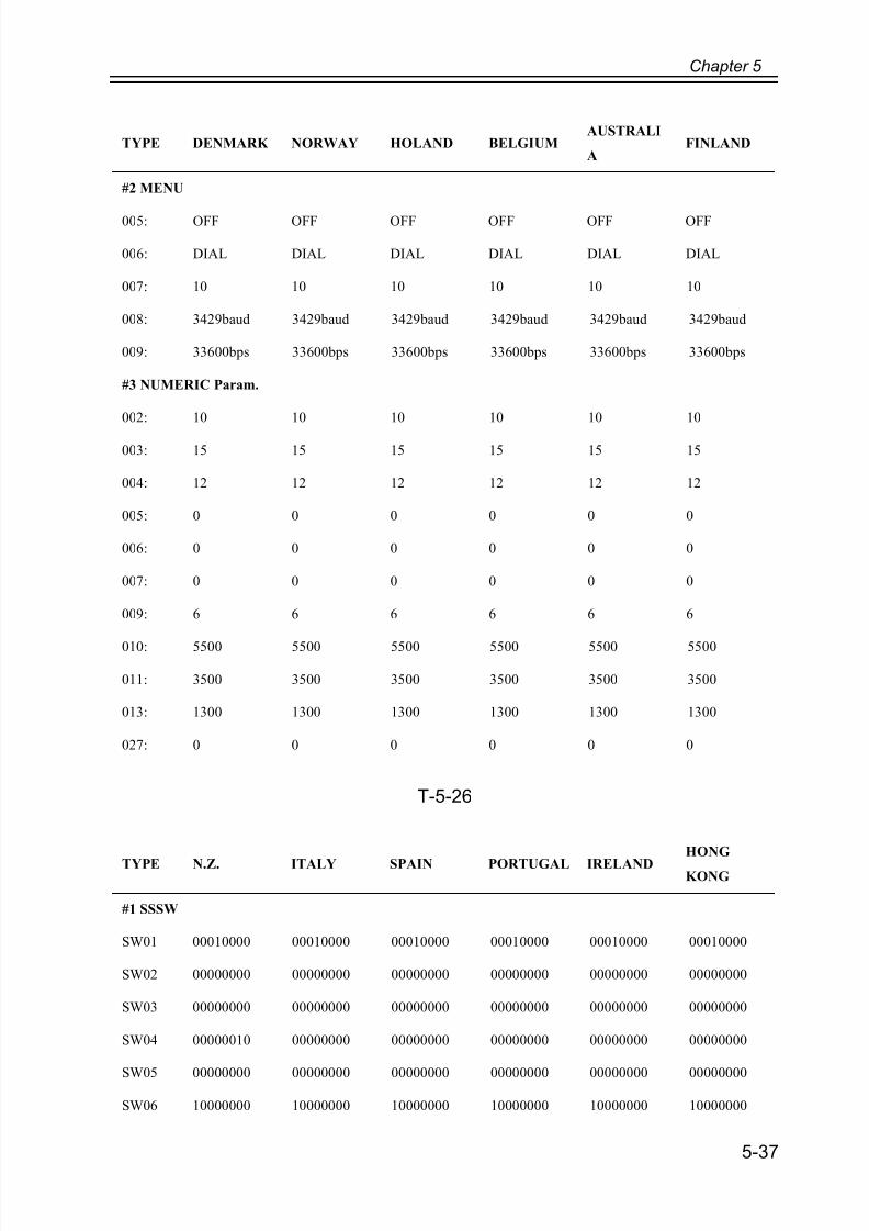
7/18/2019 Canon Fax Board N1
http://slidepdf.com/reader/full/canon-fax-board-n1 91/125
Chapter 5
5-37
T-5-26
#2 MENU
005: OFF OFF OFF OFF OFF OFF
006: DIAL DIAL DIAL DIAL DIAL DIAL
007: 10 10 10 10 10 10
008: 3429baud 3429baud 3429baud 3429baud 3429baud 3429baud
009: 33600bps 33600bps 33600bps 33600bps 33600bps 33600bps
#3 NUMERIC Param.
002: 10 10 10 10 10 10
003: 15 15 15 15 15 15
004: 12 12 12 12 12 12
005: 0 0 0 0 0 0
006: 0 0 0 0 0 0
007: 0 0 0 0 0 0
009: 6 6 6 6 6 6
010: 5500 5500 5500 5500 5500 5500
011: 3500 3500 3500 3500 3500 3500
013: 1300 1300 1300 1300 1300 1300
027: 0 0 0 0 0 0
TYPE N.Z. ITALY SPAIN PORTUGAL IRELANDHONG
KONG
#1 SSSW
SW01 00010000 00010000 00010000 00010000 00010000 00010000
SW02 00000000 00000000 00000000 00000000 00000000 00000000
SW03 00000000 00000000 00000000 00000000 00000000 00000000
SW04 00000010 00000000 00000000 00000000 00000000 00000000
SW05 00000000 00000000 00000000 00000000 00000000 00000000
SW06 10000000 10000000 10000000 10000000 10000000 10000000
TYPE DENMARK NORWAY HOLAND BELGIUMAUSTRALI
AFINLAND

7/18/2019 Canon Fax Board N1
http://slidepdf.com/reader/full/canon-fax-board-n1 92/125
Chapter 5
5-38
SW07 00000000 00000000 00000000 00000000 00000000 00000000
SW08 00000000 00000000 00000000 00000000 00000000 00000000
SW09 00000000 00000000 00000000 00000000 00000000 00000000
SW10 00000000 00000000 00000000 00000000 00000000 00000000
SW11 00000000 00000000 00000000 00000000 00000000 00000000
SW12 00000011 00000011 00000011 00000011 00000011 00000011
SW13 00000000 00000000 00000000 00000000 00000000 00000000
SW14 00000000 00000000 00000000 00000000 00000000 00000000
SW15 00000000 00000000 00000000 00000000 00000000 00000000
SW16 00000000 00000000 00000000 00000000 00000000 00000000
SW17 00000000 00000000 00000000 00000000 00000000 00000000
SW18 00000000 00000000 00000000 00000000 00000000 00000000
SW19 00000000 00000000 00000000 00000000 00000000 00000000
SW20 00000000 00000000 00000000 00000000 00000000 00000000
SW21 00000000 00000000 00000000 00000000 00000000 00000000
SW22 00000000 00000000 00000000 00000000 00000000 00000000
SW23 00000000 00000000 00000000 00000000 00000000 00000000
SW24 00000000 00000000 00000000 00000000 00000000 00000000
SW25 00000000 00000000 00000000 00000000 00000000 00000000
SW26 00100000 00100000 00100000 00100000 00100000 00100000
SW27 00000000 00000000 00000000 00000000 00000000 00000000
SW28 00000000 00000000 00000000 00000000 00000000 00000000
#2 MENU
005: OFF OFF OFF OFF OFF OFF
006: DIAL DIAL DIAL DIAL DIAL DIAL
007: 10 10 10 10 10 10
008: 3429baud 3429baud 3429baud 3429baud 3429baud 3429baud
009: 33600bps 33600bps 33600bps 33600bps 33600bps 33600bps
TYPE N.Z. ITALY SPAIN PORTUGAL IRELANDHONG
KONG
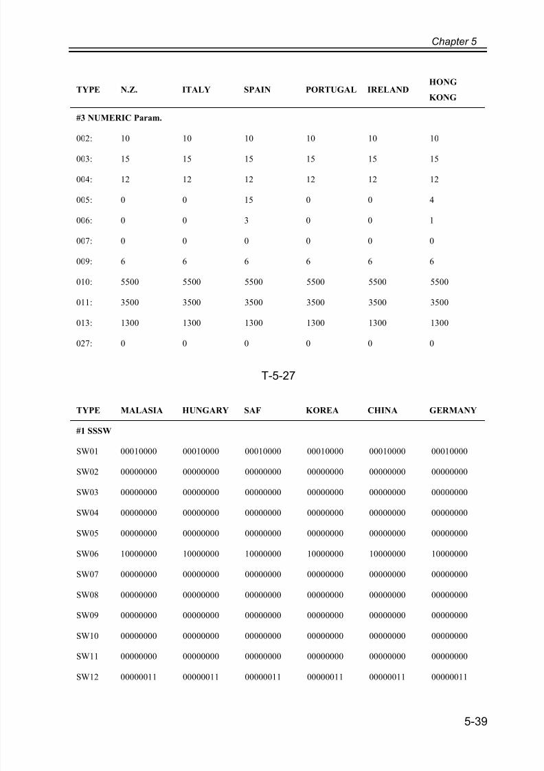
7/18/2019 Canon Fax Board N1
http://slidepdf.com/reader/full/canon-fax-board-n1 93/125
Chapter 5
5-39
T-5-27
#3 NUMERIC Param.
002: 10 10 10 10 10 10
003: 15 15 15 15 15 15
004: 12 12 12 12 12 12
005: 0 0 15 0 0 4
006: 0 0 3 0 0 1
007: 0 0 0 0 0 0
009: 6 6 6 6 6 6
010: 5500 5500 5500 5500 5500 5500
011: 3500 3500 3500 3500 3500 3500
013: 1300 1300 1300 1300 1300 1300
027: 0 0 0 0 0 0
TYPE MALASIA HUNGARY SAF KOREA CHINA GERMANY
#1 SSSW
SW01 00010000 00010000 00010000 00010000 00010000 00010000
SW02 00000000 00000000 00000000 00000000 00000000 00000000
SW03 00000000 00000000 00000000 00000000 00000000 00000000
SW04 00000000 00000000 00000000 00000000 00000000 00000000
SW05 00000000 00000000 00000000 00000000 00000000 00000000
SW06 10000000 10000000 10000000 10000000 10000000 10000000
SW07 00000000 00000000 00000000 00000000 00000000 00000000
SW08 00000000 00000000 00000000 00000000 00000000 00000000
SW09 00000000 00000000 00000000 00000000 00000000 00000000
SW10 00000000 00000000 00000000 00000000 00000000 00000000
SW11 00000000 00000000 00000000 00000000 00000000 00000000
SW12 00000011 00000011 00000011 00000011 00000011 00000011
TYPE N.Z. ITALY SPAIN PORTUGAL IRELANDHONG
KONG

7/18/2019 Canon Fax Board N1
http://slidepdf.com/reader/full/canon-fax-board-n1 94/125
Chapter 5
5-40
SW13 00000000 00000000 00000000 00000000 00000000 00000000
SW14 00000000 00000000 00000000 00000000 00000000 00000000
SW15 00000000 00000000 00000000 00000000 00000000 00000000
SW16 00000000 00000000 00000000 00000000 00000000 00000000
SW17 00000000 00000000 00000000 00000000 00000000 00000000
SW18 00000000 00000000 00000000 00000000 00000000 00000000
SW19 00000000 00000000 00000000 00000000 00000000 00000000
SW20 00000000 00000000 00000000 00000000 00000000 00000000
SW21 00000000 00000000 00000000 00000000 00000000 00000000
SW22 00000000 00000000 00000000 00000000 00000000 00001000
SW23 00000000 00000000 00000000 00000000 00000000 00000000
SW24 00000000 00000000 00000000 00000000 00000000 00000000
SW25 00000000 00000001 00000000 00000000 00000000 00000101
SW26 00100000 00100000 00100000 00100000 00100000 00100000
SW27 00000000 00000000 00000000 00000000 00000000 00000000
SW28 00000000 00000000 00000000 00000000 00000000 00000000
#2 MENU
005: OFF OFF OFF OFF OFF OFF
006: DIAL DIAL DIAL DIAL DIAL DIAL
007: 10 10 10 10 13 10
008: 3429baud 3429baud 3429baud 3429baud 3429baud 3429baud
009: 33600bps 33600bps 33600bps 33600bps 33600bps 33600bps
#3 NUMERIC Param.
002: 10 10 10 10 10 10
003: 15 15 15 15 15 15
004: 12 12 12 12 12 6
005: 0 0 0 4 0 0
006: 0 0 0 4 0 0
007: 0 0 0 0 0 0
TYPE MALASIA HUNGARY SAF KOREA CHINA GERMANY
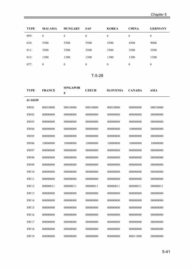
7/18/2019 Canon Fax Board N1
http://slidepdf.com/reader/full/canon-fax-board-n1 95/125
Chapter 5
5-41
T-5-28
009: 6 6 6 6 6 6
010: 5500 5500 5500 5500 4500 9000
011: 3500 3500 3500 3500 3500 3500
013: 1300 1300 1300 1300 1300 1300
027: 0 0 0 0 0 0
TYPE FRANCESINGAPOR
E
CZECH SLOVENIA CANADA ASIA
#1 SSSW
SW01 00010000 00010000 00010000 00010000 00000000 00010000
SW02 00000000 00000000 00000000 00000000 00000000 00000000
SW03 00000000 00000000 00000000 00000000 00000000 00000000
SW04 00000000 00000000 00000000 00000000 10000000 00000000
SW05 00000000 00000000 00000000 00000000 00000000 00000000
SW06 10000000 10000000 10000000 10000000 10000000 10000000
SW07 00000000 00000000 00000000 00000000 00000000 00000000
SW08 00000000 00000000 00000000 00000000 00000000 00000000
SW09 00000000 00000000 00000000 00000000 00000000 00000000
SW10 00000000 00000000 00000000 00000000 00000000 00000000
SW11 00000000 00000000 00000000 00000000 00000000 00000000
SW12 00000011 00000011 00000011 00000011 00000011 00000011
SW13 00000000 00000000 00000000 00000000 00000000 00000000
SW14 00000000 00000000 00000000 00000000 00000000 00000000
SW15 00000000 00000000 00000000 00000000 00000000 00000000
SW16 00000000 00000000 00000000 00000000 00000000 00000000
SW17 00000000 00000000 00000000 00000000 00000000 00000000
SW18 00000000 00000000 00000000 00000000 00000000 00000000
SW19 00000000 00000000 00000000 00000000 00011000 00000000
TYPE MALASIA HUNGARY SAF KOREA CHINA GERMANY

7/18/2019 Canon Fax Board N1
http://slidepdf.com/reader/full/canon-fax-board-n1 96/125
Chapter 5
5-42
SW20 00000000 00000000 00000000 00000000 00000000 00000000
SW21 00000000 00000000 00000000 00000000 00000000 00000000
SW22 00000000 00000000 00000000 00000000 00000000 00000000
SW23 00000000 00000000 00000000 00000000 00000000 00000000
SW24 00000000 00000000 00000000 00000000 00000000 00000000
SW25 00000000 00000000 00000000 00000000 00000000 00000000
SW26 00100000 00100000 00100000 00100000 00100000 00100000
SW27 00000000 00000000 00000000 00000000 00000000 00000000
SW28 00000000 00000000 00000000 00000000 00000000 00000000
#2 MENU
005: OFF OFF OFF OFF OFF OFF
006: DIAL DIAL DIAL DIAL DIAL DIAL
007: 10 10 10 10 10 10
008: 3429baud 3429baud 3429baud 3429baud 3429baud 3429baud
009: 33600bps 33600bps 33600bps 33600bps 33600bps 33600bps
#3 NUMERIC Param.
002: 10 10 10 10 10 10
003: 15 15 15 15 15 15
004: 12 12 12 12 12 12
005: 0 0 4 0 4 4
006: 0 0 4 0 4 4
007: 0 0 0 0 0 0
009: 6 6 6 6 6 6
010: 5500 5500 5500 5500 5500 5500
011: 3800 3500 3500 3500 3500 3500
013: 1300 1300 1300 1300 1300 1300
027: 0 0 0 0 0 0
TYPE FRANCESINGAPOR
ECZECH SLOVENIA CANADA ASIA

7/18/2019 Canon Fax Board N1
http://slidepdf.com/reader/full/canon-fax-board-n1 97/125
Chapter 5
5-43
T-5-29
TYPE POLAND EUROPE2 TAIWAN
#1 SSSW
SW01 00010000 00010000 00000000
SW02 00000000 00000000 00000000
SW03 00000000 00000000 00000000
SW04 00000000 00000000 10000000
SW05 00000000 00000000 00000000
SW06 10000000 10000000 10000000
SW07 00000000 00000000 00000000
SW08 00000000 00000000 00000000
SW09 00000000 00000000 00000000
SW10 00000000 00000000 00000000
SW11 00000000 00000000 00000000
SW12 00000011 00000011 00000011
SW13 00000000 00000000 00000000
SW14 00000000 00000000 00000000
SW15 00000000 00000000 00000000
SW16 00000000 00000000 00000000
SW17 00000000 00000000 00000000
SW18 00000000 00000000 00000000
SW19 00000000 00000000 00000000
SW20 00000000 00000000 00000000
SW21 00000000 00000000 00000000
SW22 00000000 00000000 00000000
SW23 00000000 00000000 00000000
SW24 00000000 00000000 00000000
SW25 00000000 00000000 00000000
SW26 00100000 00100000 00100000
SW27 00000000 00000000 00000000

7/18/2019 Canon Fax Board N1
http://slidepdf.com/reader/full/canon-fax-board-n1 98/125
Chapter 5
5-44
SW28 00000000 00000000 00000000
#2 MENU
005: OFF OFF OFF
006: DIAL DIAL DIAL
007: 10 10 10
008: 3429baud 3429baud 3429baud
009: 33600bps 33600bps 33600bps
#3 NUMERIC Param.
002: 10 10 10
003: 15 15 15
004: 12 12 12
005: 4 4 4
006: 4 4 4
007: 0 0 0
009: 6 6 6
010: 5500 5500 5500
011: 3500 3500 3500
013: 1300 1300 1300
027: 0 0 0
TYPE POLAND EUROPE2 TAIWAN

7/18/2019 Canon Fax Board N1
http://slidepdf.com/reader/full/canon-fax-board-n1 99/125
Chapter 5
5-45
5.9 Test Mode (TEST)
5.9.1 Outline
5.9.1.1 Test Mode Construction
F-5-14
<Using Test Mode>
- Press the desired item to highlight; then, press the OK key to bring up its screen.
The following table shows text mode items that are valid and invalid when a fax board is
installed:
yes: may be used
no: not used
ReportSssw Menu Num Ncu Type ISDN Print Clear Test
MODEM
FACULTY
DATA SET
ISDNMOD
ISDNMOD2

7/18/2019 Canon Fax Board N1
http://slidepdf.com/reader/full/canon-fax-board-n1 100/125
Chapter 5
5-46
T-5-30
Do not use items in the table identified as "no."
5.9.2 MODEM Test
5.9.2.1 Relay Test (RELAY-1)
Use it to see if the individual relays on the NCU board go on and off as expected.
Level 1 Level 2 Super G3 Fax Board present
MODEM RELAY-1 yes
RELAY-2 no
FREQ yes
G3TX yes
DTMFTX yes
TONERX no
V34G3TX yes
FACULTY G3 4800TX yes
SPEAKER no
LINE DETECT1 no
LINE DETECT2 no
LINE DETECT3 no
VOICETX no
DATA SET no
ISDNMOD no
ISDNMOD2 no
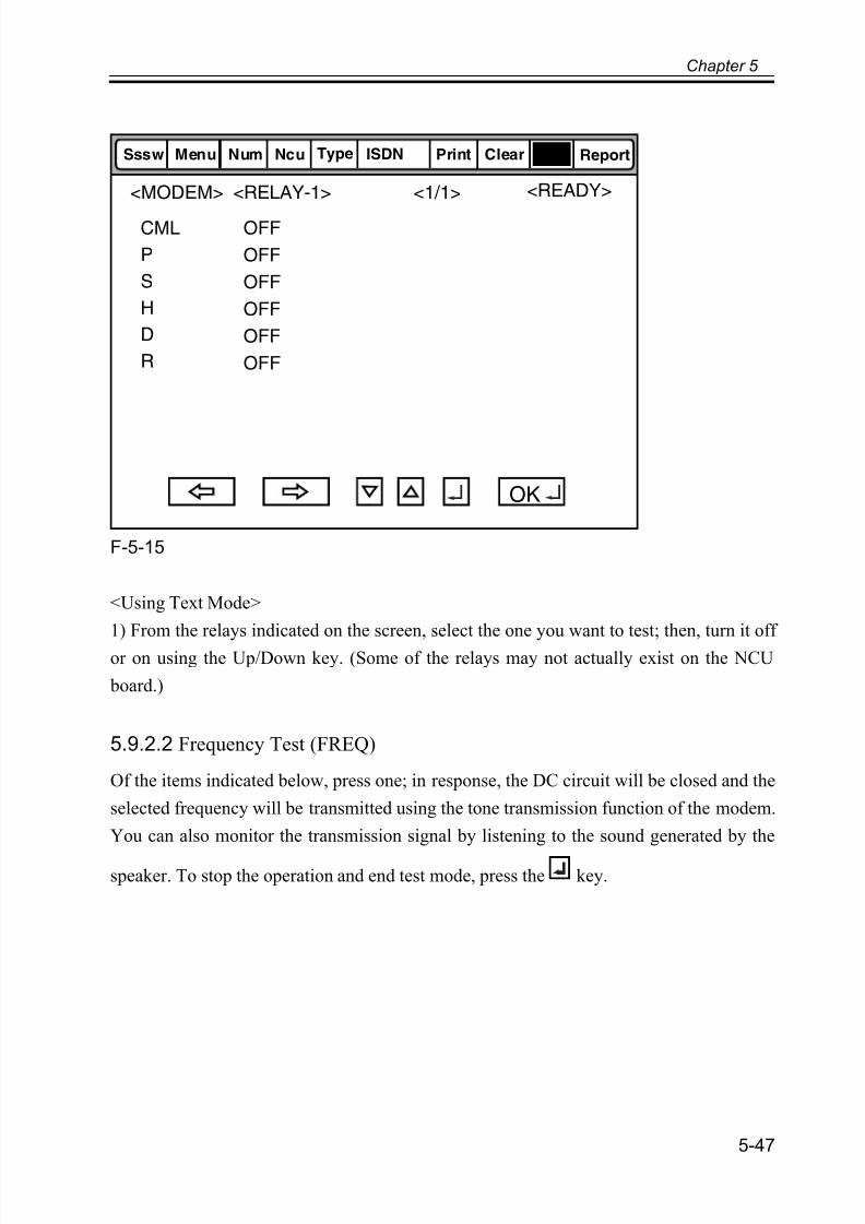
7/18/2019 Canon Fax Board N1
http://slidepdf.com/reader/full/canon-fax-board-n1 101/125
Chapter 5
5-47
F-5-15
<Using Text Mode>
1) From the relays indicated on the screen, select the one you want to test; then, turn it off
or on using the Up/Down key. (Some of the relays may not actually exist on the NCU
board.)
5.9.2.2 Frequency Test (FREQ)
Of the items indicated below, press one; in response, the DC circuit will be closed and the
selected frequency will be transmitted using the tone transmission function of the modem.
You can also monitor the transmission signal by listening to the sound generated by the
speaker. To stop the operation and end test mode, press the key.
<1/1><MODEM> <READY>
ReportSssw Menu Num Ncu Type ISDN Print Clear Test
CML
P
S
H
D
R
<RELAY-1>
OFF
OFF
OFF
OFF
OFF
OFF
OK
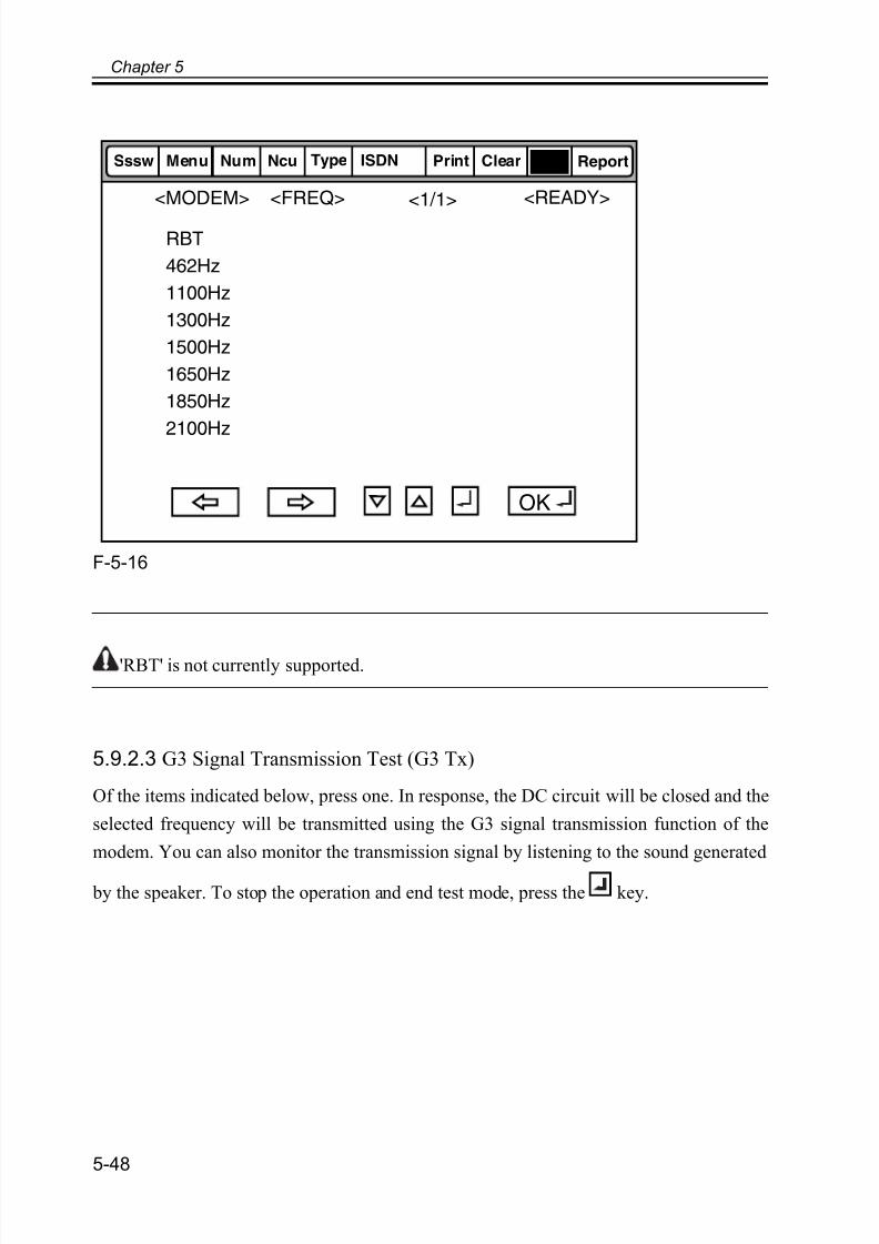
7/18/2019 Canon Fax Board N1
http://slidepdf.com/reader/full/canon-fax-board-n1 102/125
Chapter 5
5-48
F-5-16
'RBT' is not currently supported.
5.9.2.3 G3 Signal Transmission Test (G3 Tx)
Of the items indicated below, press one. In response, the DC circuit will be closed and the
selected frequency will be transmitted using the G3 signal transmission function of the
modem. You can also monitor the transmission signal by listening to the sound generated
by the speaker. To stop the operation and end test mode, press the key.
<1/1> <READY>
ReportSssw Menu Num Ncu Type ISDN Print Clear Test
<FREQ><MODEM>
OK
RBT
462Hz
1100Hz
1300Hz
1500Hz
1650Hz
1850Hz
2100Hz

7/18/2019 Canon Fax Board N1
http://slidepdf.com/reader/full/canon-fax-board-n1 103/125
Chapter 5
5-49
F-5-17
F-5-18
'300-ALL0' through '300-4:1' are not currently supported.
<1/2> <READY>
ReportSssw Menu Num Ncu Type ISDN Print Clear Test
<G3TX><MODEM>
OK
300bps
2400bps
4800bps
7200bps
9600bps
TC7200
TC9600
12000bps
<2/2> <READY>
ReportSssw Menu Num Ncu Type ISDN Print Clear Test
<G3TX><MODEM>
OK
14400bps
300-ALL0
300-ALL1
300-1:1
300-1:4
300-4:1
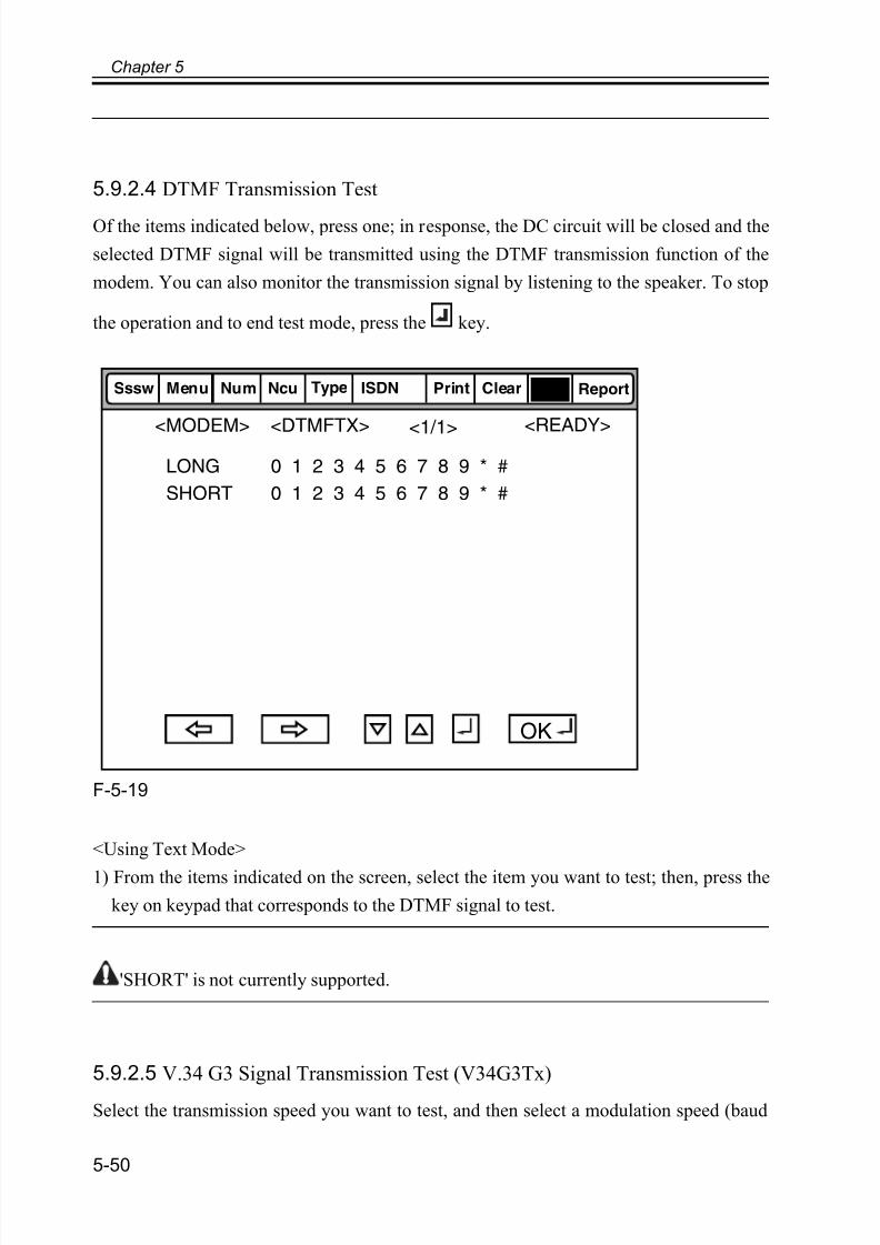
7/18/2019 Canon Fax Board N1
http://slidepdf.com/reader/full/canon-fax-board-n1 104/125
Chapter 5
5-50
5.9.2.4 DTMF Transmission Test
Of the items indicated below, press one; in response, the DC circuit will be closed and the
selected DTMF signal will be transmitted using the DTMF transmission function of the
modem. You can also monitor the transmission signal by listening to the speaker. To stop
the operation and to end test mode, press the key.
F-5-19
<Using Text Mode>
1) From the items indicated on the screen, select the item you want to test; then, press the
key on keypad that corresponds to the DTMF signal to test.
'SHORT' is not currently supported.
5.9.2.5 V.34 G3 Signal Transmission Test (V34G3Tx)
Select the transmission speed you want to test, and then select a modulation speed (baud
<1/1><READY>
ReportSssw Menu Num Ncu Type ISDN Print Clear Test
<DTMFTX><MODEM>
OK
LONG
SHORT
0 1 2 3 4 5 6 7 8 9 * #
0 1 2 3 4 5 6 7 8 9 * #

7/18/2019 Canon Fax Board N1
http://slidepdf.com/reader/full/canon-fax-board-n1 105/125
Chapter 5
5-51
rate); in response, the V.34 G3 transmission signal will be transmitted to the telephone line
terminal and the speaker. To stop the operation and to end test mode, press the key.
F-5-20
<Using Text Mode>
1) Select 'SPEED', and then select the speed you want to test using the Up/Down key.
2) Select the baud rate you want to test.
5.9.3 Function Test
5.9.3.1 4800-bps Signal Transmission Test
The DC circuit will be closed, and a 4800-bps signal will be transmitted using the 4800-bps
signal transmission function of the modem. You can also monitor the transmission signal
by listening to the speaker. To stop the operation and end test mode, press the key.
<1/1> <READY>
ReportSssw Menu Num Ncu Type ISDN Print Clear Test
<V34G3TX><MODEM>
OK
SPEED 33600bps
3429baud
3200baud
3000baud
2800baud
2743baud
2400baud
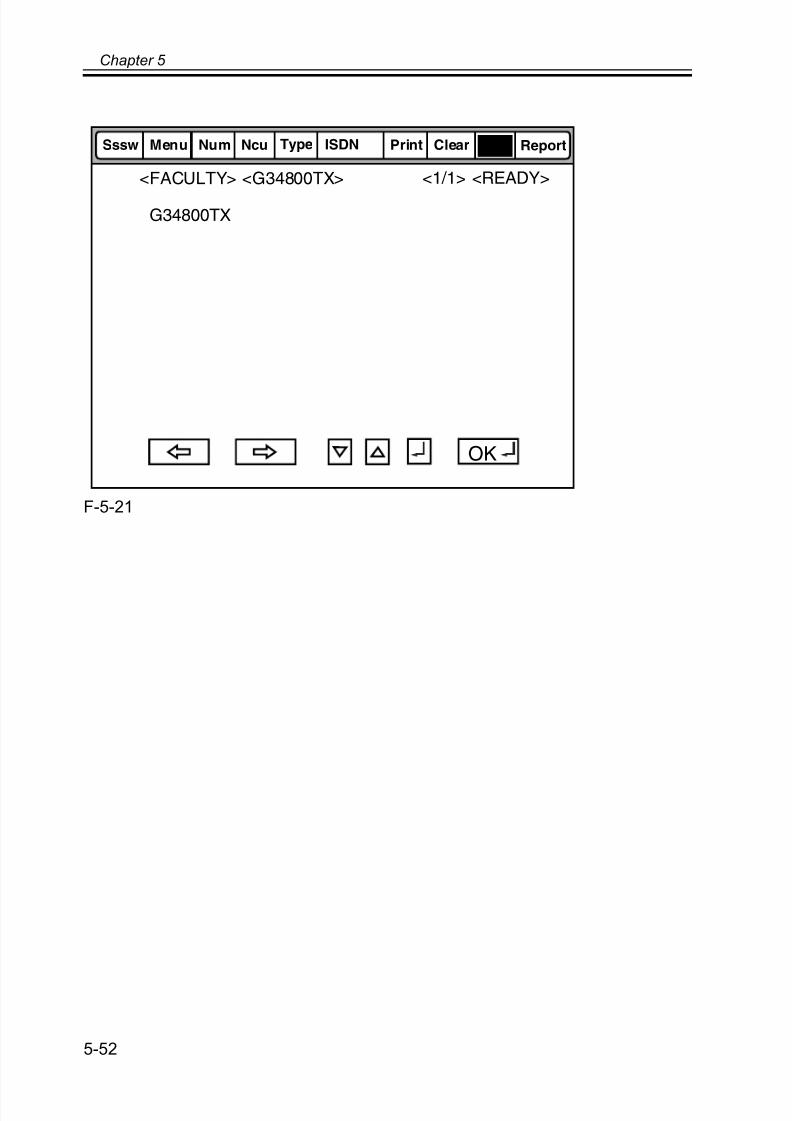
7/18/2019 Canon Fax Board N1
http://slidepdf.com/reader/full/canon-fax-board-n1 106/125
Chapter 5
5-52
F-5-21
<READY><1/1>
ReportSssw Menu Num Ncu Type ISDN Print Clear Test
<FACULTY> <G34800TX>
OK
G34800TX

7/18/2019 Canon Fax Board N1
http://slidepdf.com/reader/full/canon-fax-board-n1 107/125
Chapter 5
5-53
5.10 Service Report (REPORT)
5.10.1 System Data List
Use it to check the settings associated with the service soft switch and service parameters.
F-5-22

7/18/2019 Canon Fax Board N1
http://slidepdf.com/reader/full/canon-fax-board-n1 108/125
Chapter 5
5-54
5.10.2 System Dump List
Memo:
A system dump list is generated when you execute the following in service mode:
fax>report>data.
- System Dump List
Use it to check the history of communications, both successful and error.
F-5-23
*1: RX, number of total pages received; TX, number of total pages sent.
*2: number of pages sent/received according to original size.
*3: number of pages sent/received in connection with different modem speeds (Standard,
Fine, Super Fine, Ultra Fine).
*4: number of pages sent/received in connection with different modes.
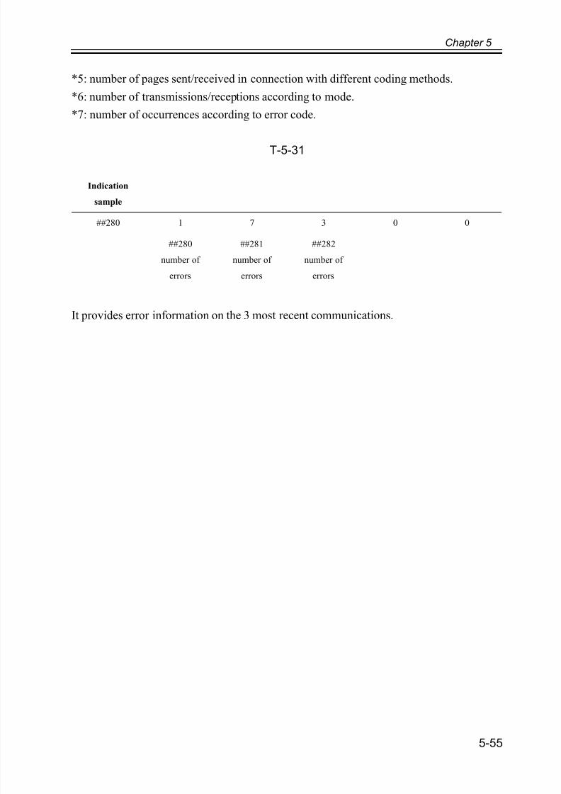
7/18/2019 Canon Fax Board N1
http://slidepdf.com/reader/full/canon-fax-board-n1 109/125
Chapter 5
5-55
*5: number of pages sent/received in connection with different coding methods.
*6: number of transmissions/receptions according to mode.
*7: number of occurrences according to error code.
T-5-31
It provides error information on the 3 most recent communications.
Indication
sample
##280 1 7 3 0 0
##280
number of
errors
##281
number of
errors
##282
number of
errors

7/18/2019 Canon Fax Board N1
http://slidepdf.com/reader/full/canon-fax-board-n1 110/125
Chapter 5
5-56
F-5-24
*1: service error code.
*2: START TIME, date and time (in 24-hr notation).
*3: OTHER PARTY, telephone number sent by the other party.
*4: MAKER CODE, manufacturer code.
*5: MACHINE CODE, model code.*6: bit 1 through bit 96 of DIS, DCS, or DTC that has been received.

7/18/2019 Canon Fax Board N1
http://slidepdf.com/reader/full/canon-fax-board-n1 111/125
Chapter 5
5-57
*7: bit 1 through bit 96 of DIS, DCS, or DTC that has been transmitted.
*8: RX, procedural signal received; TX, procedural signal transmitted.
5.10.3 Error Transmission ReportAn error transmission report is an error transmission report together to which a service error
code and error dump list is attached.
F-5-25

7/18/2019 Canon Fax Board N1
http://slidepdf.com/reader/full/canon-fax-board-n1 112/125
7/18/2019 Canon Fax Board N1
http://slidepdf.com/reader/full/canon-fax-board-n1 113/125
Chapter 6
Error Code

7/18/2019 Canon Fax Board N1
http://slidepdf.com/reader/full/canon-fax-board-n1 114/125

7/18/2019 Canon Fax Board N1
http://slidepdf.com/reader/full/canon-fax-board-n1 115/125
Contents
Contents
6.1 Overview ....................................................................................................6-1
6.1.1 Guide to Error Code............................................................................6-1
6.2 User Error Code .........................................................................................6-4
6.2.1 User Error Code ..................................................................................6-4
6.3 Service Error Code.....................................................................................6-5
6.3.1 Service Error Code..............................................................................6-5

7/18/2019 Canon Fax Board N1
http://slidepdf.com/reader/full/canon-fax-board-n1 116/125

7/18/2019 Canon Fax Board N1
http://slidepdf.com/reader/full/canon-fax-board-n1 117/125
Chapter 6
6-1
6.1 Overview
6.1.1 Guide to Error Code
When the Board has been installed and '1' is set for service data #1 SSSW SW01 bit 0,
communications ending in error will be indicated in the following reports using service
error codes: communications management report, reception result report, and error
transmission report.
You can also check the code of an error by making the following selections: System
Monitor > Fax > Detail.
F-6-1
The major error codes used by the Board are listed on the pages that follow. For informationon causes and remedies in connection with other error codes, see the "G3/G4 Facsimile
Error Code List" (HY8-23A0-020).
If the Board indicates a service error code, try the following:
- Increase the transmission level.
Set -8 (dBm) for service data #2 MENU parameter No. 007.
- Decrease the transmission level.
Set -15 (dBm) to service data #2 MENU parameter No. 007.
- Provide a remedy against echoes.
Change the following bit setting for service data #1 SSSW SW03:

7/18/2019 Canon Fax Board N1
http://slidepdf.com/reader/full/canon-fax-board-n1 118/125
Chapter 6
6-2
T-6-1
- EPT (echo protect tone)
Change the setting of service data #1 SSSW SW03 bit 1:
T-6-2
- Adjust the NL equalizer.
Set '1' for serve data #2 MENU parameter No. 005.
- Decrease the transmission start speed. Decrease the transmission start speed in user mode: System Settings > Communications
Settings > Fax Settings > Send Start Speed.
- Make the TCF evaluation standards lenient.
The Board does not offer a means by which to provide this remedy.
- Make the RTN transmissions conditions lenient.
Change parameters No. 2 through No. 004 of service data #3 NUMERIC Param.
Bit4 -> 1: to cause the machine to ignore the first DIS signal from the other party.
-> 0: to cause the machine to ignore the first DIS signal from the other party.
Bit5 -> 1: to cause the machine to transmit a tonal signal (1850 or 1650 Hz) in response
to the DIS signal from the other party.
-> 0: to cause the machine not to send a total signal (1850 or 1650 Hz) in response
to the DIS signal from the other party.
Bit6 -> 1: to cause the machine to send a 1850-Hz tonal signal if bit 5 is set to '1'.
-> 0: to cause the machine to send a 1650-Hz tonal signal if bit 5 is set to '1'.
Bit7 -> 1: to cause the machine to send a total signal before sending the CED signal.
-> 0: to causes the machine not to send a tonal signal before sending the CED
signal.
Bit1 -> 1: to cause the machine to send EPT.
-> 0: to cause the machine not to send EPT.

7/18/2019 Canon Fax Board N1
http://slidepdf.com/reader/full/canon-fax-board-n1 119/125
Chapter 6
6-3
No. 002: error rate for all lines; change it so that it is closer to 99%.
No. 003: number of lines in connection with bursts; change it so that it is closer to 99 lines.
No. 004: number of errors falling short of a specific number of lines in connection with
bursts; change it so that it is closer to 99.
- Increase the length of silence after reception of CFR.
Set '1' for service data #1 SSSW SW04 bit 4.
T-6-3
Bit4 -> 1: length of time during which a low-speed signal is ignored after transmission
of CFR; 1500 msec
-> 0: length of time during which a low-speed signal is ignored after transmission
of CFR; 700 msec
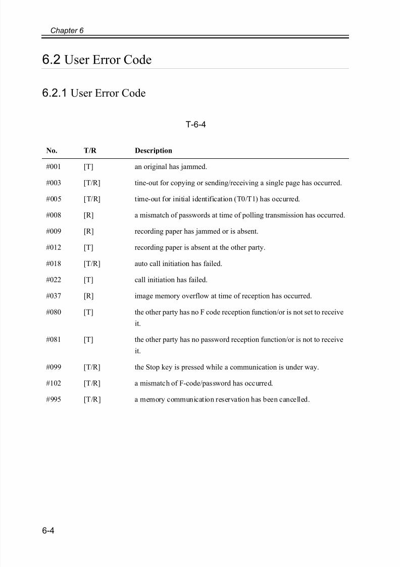
7/18/2019 Canon Fax Board N1
http://slidepdf.com/reader/full/canon-fax-board-n1 120/125
Chapter 6
6-4
6.2 User Error Code
6.2.1 User Error Code
T-6-4
No. T/R Description
#001 [T] an original has jammed.
#003 [T/R] tine-out for copying or sending/receiving a single page has occurred.
#005 [T/R] time-out for initial identification (T0/T1) has occurred.
#008 [R] a mismatch of passwords at time of polling transmission has occurred.
#009 [R] recording paper has jammed or is absent.
#012 [T] recording paper is absent at the other party.
#018 [T/R] auto call initiation has failed.
#022 [T] call initiation has failed.
#037 [R] image memory overflow at time of reception has occurred.
#080 [T] the other party has no F code reception function/or is not set to receive
it.
#081 [T] the other party has no password reception function/or is not to receive
it.
#099 [T/R] the Stop key is pressed while a communication is under way.
#102 [T/R] a mismatch of F-code/password has occurred.
#995 [T/R] a memory communication reservation has been cancelled.

7/18/2019 Canon Fax Board N1
http://slidepdf.com/reader/full/canon-fax-board-n1 121/125
Chapter 6
6-5
6.3 Service Error Code
6.3.1 Service Error Code
T-6-5
No. T/R Description
##100 [T] at time of transmission, the procedural signal has been transmitted more than
specified.
##101 [T/R] the modem speed does not match that of the other party.
##102 [T] at time of transmission, fall-back cannot be used.
##103 [R] at time of reception, EOL cannot be detected for 5 sec (15 sec if CBT).
##104 [T] at time of transmission, RTN or PIN is received.
##106 [R] at time of reception, the procedural signal is received for 6 sec while in wait for
the signal.
##107 [R] at time of reception, the transmitting party cannot use fall-back.
##109 [T] at time of transmission, a signal other than DIS, DTC, FTT, CFR, or CRP is
received, and the procedural signal has been sent more than specified.
##111 [T/R] memory error has occurred.
##114 [R] at time of reception, RTN is transmitted.
##200 [R] at time of reception, no image carrier is detected for 5 sec.
##201 [T/R] DCN is received outside the normal parity procedure.
##204 [T] DTC without transmission data is received.
##220 [T/R] system error (main program out of control) has occurred.
##223 [T/R] while a communication is under way, the line is cut.
##224 [T/R] in G3 communication, an error has occurred in the procedural signal.
##226 [T/R] the stack printer has fallen outside the RAM area.
##229 [R] the recording unit has remained locked for 1 min.
##232 [T] encoding error has occurred.
##237 [R] decoding error has occurred.
##238 [R] the print control unit is out of order.

7/18/2019 Canon Fax Board N1
http://slidepdf.com/reader/full/canon-fax-board-n1 122/125
Chapter 6
6-6
##261 [T/R] system error has occurred.
##280 [T] at time of transmission, the procedural signal has been transmitted more than
specified.
##281 [T] at time of transmission, the procedural signal has been transmitted more than
specified.
##282 [T] at time of transmission, the procedural signal has been transmitted more than
specified.
##283 [T] at time of transmission, the procedural signal has been transmitted more than
specified.
##284 [T] at time of transmission, DCN is received after transmission of TCF.
##285 [T] at time of transmission, DCN is received after transmission of EOP.
##286 [T] at time of transmission, DCN is received after transmission of EOM.
##287 [T] at time of transmission DCN is received after transmission of MPS.
##288 [T] after transmission of EOP, a signal other than PIN, PIP, MCF, RTP, or RTN has
been received.
##289 [T] after transmission of EOM, a signal other than PIN, PIP, MCF, RTP, or RTN has
been received.
##290 [T] after transmission of MPS, a signal other than PIN, PIP, MCF, RTP, or RTN has
been received.
##670 [T] at time of V.8 late start, the V.8 ability of DIS front the receiving party is expected
to be detected, and the CI signal is expected to be transmitted in response;
however, the procedure fails to advance, and the line is released because of T1
time-out.
##671 [R] at time of V.8 arrival, procedure fails to move to phase 2 after detection of CM
signal from caller, causing T1 time-out and releasing line
##672 [T] at time of V.34 transmission, a shift in procedure from phase 2 to phase 3 and
thereafter stops, causing the machine to release the line and suffer T1 timeout.
##673 [R] at time of V.34 reception, a shift in procedure from phase 2 to phase 3 and
thereafter stops, causing the machine to release the line and suffer T1 timeout.
##674 [T] at time of V.34 transmission, a shift in procedure from phase 3 and phase 4 to the
control channel and thereafter stops, causing the machine to release the line and
suffer T1 timeout.
No. T/R Description

7/18/2019 Canon Fax Board N1
http://slidepdf.com/reader/full/canon-fax-board-n1 123/125
Chapter 6
6-7
##675 [R] at time of V.34 reception, a shift in procedure from phase 3 and phase 4 to the
control channel and thereafter stops, causing the machine to release the line and
suffer T1 timeout.
##750 [T] at time of ECM transmission, no meaningful signal is received after transmission
of PPS-NULL, causing the procedural signal to be transmitted more than
specified.
##752 [T] at time of ECM transmission, DCN is received after transmission of PPS-NULL.
##753 [T] at time of ECM transmission, the procedural signal has been transmitted more than
specified after transmission of PPS-NULL, or T5 time-out (60 sec) has occurred.
##754 [T] at time of ECM transmission, the procedural signal has been transmitted more than
specified after transmission of PPS-NULL.
##755 [T] at time of ECM transmission, no meaningful signal is received after transmission
of PPS-MPS, causing the procedural signal to be transmitted more than specified.
##757 [T] at time of ECM transmission, DCN is received after retransmission of PPS-MPS.
##758 [T] at time of ECM transmission, the procedural signal has been transmitted more than
specified after transmission of PPS-MPS, or T5 time-out (60 sec) has occurred.
##759 [T] at time of ECM transmission, the procedural signal has been transmitted more than
specified after transmission of PPS-MPS.
##760 [T] at time of ECM transmission, no meaningful signal is received after transmission
of PPS-EOM, causing the procedural signal to be transmitted more than specified.
##762 [T] at time of ECM transmission, DCN is received after transmission of PPS-EOM.
##763 [T] at time of ECM transmission, the procedural signal has been transmitted more than
specified after transmission of PPS-MPS, or T5 time-out (60 sec) has occurred.
##764 [T] at time of ECM transmission, the procedural signal has been transmitted more than
specified after transmission of PPS-EOM.
##765 [T] at time of ECM transmission, no meaningful signal is received after transmission
of PPS-EOP, causing the procedural signal to be transmitted more than specified.
##767 [T] at time of ECM transmission, DCN is received after transmission of PPS-EOP.
##768 [T] at time of ECM transmission, the procedural signal has been transmitted more than
specified after transmission of PPS-EOP, or T5 time-out (60 sec) has occurred.
##769 [T] at time of ECM transmission, the procedural signal has been transmitted more than
specified after transmission of PPS-EOP.
No. T/R Description
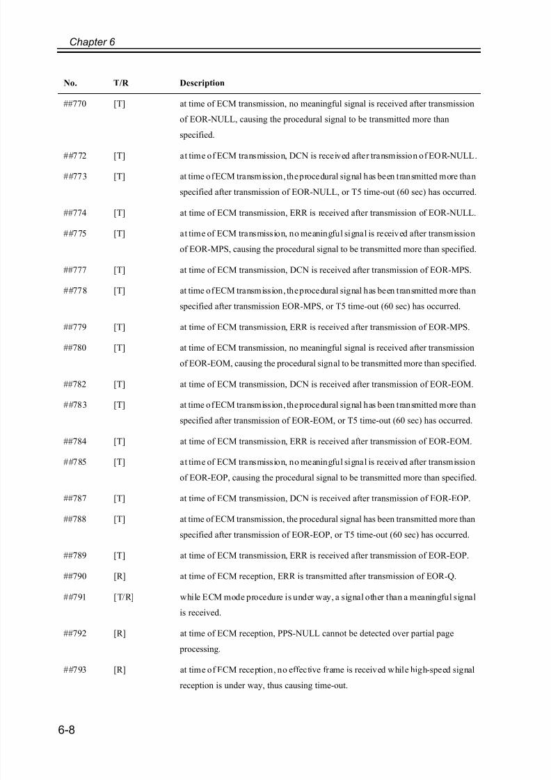
7/18/2019 Canon Fax Board N1
http://slidepdf.com/reader/full/canon-fax-board-n1 124/125
Chapter 6
6-8
##770 [T] at time of ECM transmission, no meaningful signal is received after transmission
of EOR-NULL, causing the procedural signal to be transmitted more than
specified.
##772 [T] at time of ECM transmission, DCN is received after transmission of EOR-NULL.
##773 [T] at time of ECM transmission, the procedural signal has been transmitted more than
specified after transmission of EOR-NULL, or T5 time-out (60 sec) has occurred.
##774 [T] at time of ECM transmission, ERR is received after transmission of EOR-NULL.
##775 [T] at time of ECM transmission, no meaningful signal is received after transmission
of EOR-MPS, causing the procedural signal to be transmitted more than specified.
##777 [T] at time of ECM transmission, DCN is received after transmission of EOR-MPS.
##778 [T] at time of ECM transmission, the procedural signal has been transmitted more than
specified after transmission EOR-MPS, or T5 time-out (60 sec) has occurred.
##779 [T] at time of ECM transmission, ERR is received after transmission of EOR-MPS.
##780 [T] at time of ECM transmission, no meaningful signal is received after transmission
of EOR-EOM, causing the procedural signal to be transmitted more than specified.
##782 [T] at time of ECM transmission, DCN is received after transmission of EOR-EOM.
##783 [T] at time of ECM transmission, the procedural signal has been transmitted more thanspecified after transmission of EOR-EOM, or T5 time-out (60 sec) has occurred.
##784 [T] at time of ECM transmission, ERR is received after transmission of EOR-EOM.
##785 [T] at time of ECM transmission, no meaningful signal is received after transmission
of EOR-EOP, causing the procedural signal to be transmitted more than specified.
##787 [T] at time of ECM transmission, DCN is received after transmission of EOR-EOP.
##788 [T] at time of ECM transmission, the procedural signal has been transmitted more than
specified after transmission of EOR-EOP, or T5 time-out (60 sec) has occurred.
##789 [T] at time of ECM transmission, ERR is received after transmission of EOR-EOP.
##790 [R] at time of ECM reception, ERR is transmitted after transmission of EOR-Q.
##791 [T/R] while ECM mode procedure is under way, a signal other than a meaningful signal
is received.
##792 [R] at time of ECM reception, PPS-NULL cannot be detected over partial page
processing.
##793 [R] at time of ECM reception, no effective frame is received while high-speed signal
reception is under way, thus causing time-out.
No. T/R Description

7/18/2019 Canon Fax Board N1
http://slidepdf.com/reader/full/canon-fax-board-n1 125/125
Chapter 6
##794 [T] at time of ECM reception, PPR with all 0s is received.
##795 [T/R] a fault has occurred in code processing for communication.
##796 [T/R] a fault has occurred in decoding processing after reception of ECM
No. T/R Description