Embed Size (px)
Citation preview
iR2200/iR2800/iR3300
REVISION 0
SERVICEHANDBOOK
FY8-23BD-000MAY 2001
COPYRIGHT© 2001 CANON INC. CANON iR2200/iR2800/iR3300 REV.0 MAY 2001 PRINTED IN JAPAN (IMPRIME AU JAPON)
Application
This manual has been issued by Canon Inc. for qualified persons to learn technical theory, installation,
maintenance, and repair of products. This manual covers all localities where the products are sold. For
this reason, there may be information in this manual that does not apply to your locality.
Corrections
This manual may contain technical inaccuracies or typographical errors due to improvements or
changes in products. When changes occur in applicable products or in the contents of this manual,
Canon will release technical information as the need arises. In the event of major changes in the contents
of this manual over a long or short period, Canon will issue a new edition of this manual.
The following paragraph does not apply to any countries where such provisions are inconsistent with
local law.
Trademarks
The product names and company names used in this manual are the registered trademarks of the
individual companies.
Copyright
This manual is copyrighted with all rights reserved. Under the copyright laws, this manual may not be
copied, reproduced or translated into another language, in whole or in part, without the written consent
of Canon Inc.
Caution
Use of this manual should be strictly supervised to avoid disclosure of
confidential information.
COPYRIGHT © 2001 CANON INC.
Printed in Japan
Imprimé au Japon
COPYRIGHT© 2001 CANON INC. CANON iR2200/iR2800/iR3300 REV.0 MAY 2001 PRINTED IN JAPAN (IMPRIME AU JAPON)
CONTENTS
ContentsCHAPTER 1 MAINTENANCE AND INSPECTION
CHAPTER 2 IMAGE ADJUSTMENT BASIC PROCEDURE
1 Periodically Replaced Parts .............. 1-11.1 Reader Unit ................................ 1-11.2 Printer Unit ................................ 1-11.3 Side Paper Deck ......................... 1-11.4 Cassette Feeding unit ................. 1-11.5 Inner 2-Way Tray ....................... 1-1
2 Consumables and Durables .............. 1-22.1 Checking the Time of Replacement
................................................... 1-22.2 Reader Unit ................................ 1-22.3 Printer Unit ................................ 1-22.4 Side Paper Deck ......................... 1-3
2.5 Cassette Feeding Unit ................ 1-32.6 Inner 2-Way Tray-A1 ................. 1-3
3 Periodical Servicing Procedure ........ 1-44 Scheduled Servicing Chart ............... 1-6
4.1 Reader Unit ................................ 1-64.2 Printer Unit ................................ 1-7
5 Points to Note for Scheduled Servicing.......................................................... 1-8
6 Cleaning the Bottom of the DevelopingAssembly .......................................... 1-9
6.1 Cleaning the Bottom of the Devel-oping Assembly .......................... 1-9
1 Making lnitial Checks ...................... 2-12 Checking the Scanner Side ............... 2-13 Checking the Printer Side (1/3) ........ 2-2
4 Checking the Printer Side (2/3) ........ 2-25 Checking the Printer Side (3/3) ........ 2-2
CHAPTER 3 STANDARDS AND ADJUSTMENTS1 Image Adjustments ........................... 3-1
1.1 Standards of Image Position ...... 3-11.2 Checking the Image Position ..... 3-21.3 Adjusting Left/Right lamge Margin
................................................... 3-31.3.1 Adjusting the Registration for
the Cassette Rear Front ........ 3-31.3.2 Adjusting the Registration for
the Multifeeder Rear Front............................................. 3-4
1.3.3 Adjusting the Registration forthe Deck ............................... 3-4
1.3.4 Duplex Feeding Unit ........... 3-51.4 Adjusting the Image Leading Edge
Margin ........................................ 3-5
1.5 Adjusting the Left/Right Non-ImageWidth .......................................... 3-5
1.6 Adjusting the Leading Edge Non-Image Width ............................... 3-6
2 Scanning System .............................. 3-62.1 After Replacing the Scanning Lamp
................................................... 3-62.2 Mounting the Motor Unit ........... 3-72.3 Routing the Scanner Drive Cable
................................................... 3-82.4 Adjusting the Position of the No. 1/
No. 2 Mirror Base ...................... 3-92.5 Mounting the Copyboard Glass
................................................. 3-112.6 Mounting the Reader Upper Frame
................................................. 3-12
CONTENTS
CHAPTER 4 TROUBLESHOOTING IMAGE FAULTS/MALFUNCTIONS
1 Making Initial Checks ...................... 4-11.1 Checking the Site of Installation
................................................... 4-11.2 Checking the Originals .............. 4-11.3 Checking the ADF Platen,
Copyboard cover, and Copyboardglass (standard white plate) ........ 4-1
1.4 Charging Roller and Static Elimina-tor ............................................... 4-2
1.5 Checking the Developing Assembly................................................... 4-2
1.6 Checking the Paper .................... 4-21.7 Checking the Periodically Replaced
Parts ............................................ 4-2
1.8 Image Adjustment Basic Procedure................................................... 4-2
1.9 Others ......................................... 4-32 Samples of Image Faults .................. 4-63 Troubleshooting Image Faults .......... 4-7
3.1 The copy is too light (halftone areaonly) ........................................... 4-7
3.2 The copy is too light (includingsolid black) ................................. 4-8
3.3 The copy is too light (entire face,considerable) ............................ 4-10
3.4 The copy has uneven density(darker at front) ........................ 4-12
3.5 The copy has uneven density(lighter at front) ........................ 4-12
2.7 Points to Note When Replacing theCCD Unit ................................. 3-12
2.8 When Replacing the Reader Con-troller PCB ............................... 3-12
3 Image Formation System ............... 3-133.1 Positioning the Developing Assem-
bly Magnetic Seal .................... 3-133.2 Mounting the Developing Assembly
Blade ........................................ 3-133.3 Removing the Paper Lint ......... 3-143.4 Cleaning the Waste Toner Case
................................................. 3-154 Fixing System................................. 3-16
4.1 Mounting the Locking Cam Unit................................................. 3-16
5 Paper Deck ..................................... 3-175.1 Mounting the Front Cover ....... 3-175.2 Adjusting the Paper Level Indicator
................................................. 3-185.3 Adjusting the Position of the Sup-
port Member ............................ 3-185.4 Mounting the Deck Pickup Roller
................................................. 3-19
5.5 Removing the Deck Pickup/FeedingRoller ....................................... 3-19
5.6 Orientation of the Deck Pickup/Feeding Roller .......................... 3-20
5.7 Adjusting the Deck SeparationRoller Pressure ......................... 3-20
5.8 Position of the Deck Pickup RollerReleasing Solenoid (SL1D) ..... 3-21
5.9 Adjusting the Height of the SideMember .................................... 3-22
5.9.1 Before Making Adjustments........................................... 3-22
5.9.2 Making Adjustments .......... 3-226 Cassette Feeding Unit-W1 ............. 3-23
6.1 Mounting the Pedestal Main Motor................................................. 3-23
7 Envelope Feeder Attachment .......... 3-247.1 Envelopes and Type of Spring
................................................. 3-247.2 Replacing the Spring ................ 3-24
7.2.1 Replacing the Spring ......... 3-247.3 Changing the Size .................... 3-25
7.3.1 Changing the Size .............. 3-25
CONTENTS
3.6 The copy is foggy (entire face)................................................. 4-13
3.7 The copy is foggy (vertical) ..... 4-143.8 The copy has a black line (vertical,
fuzzy, thick) ............................. 4-143.9 The copy has a black line (vertical,
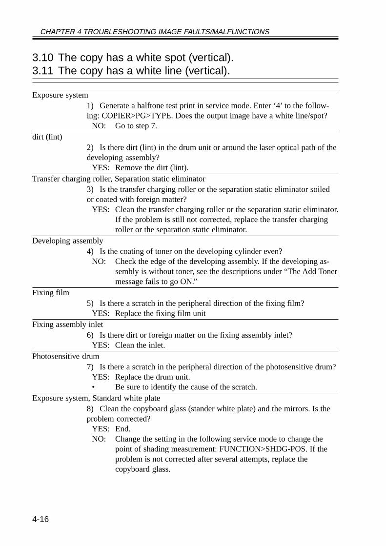
fine) .......................................... 4-153.10 The copy has a white spot (vertical)
................................................. 4-163.11 The copy has a white line (vertical)
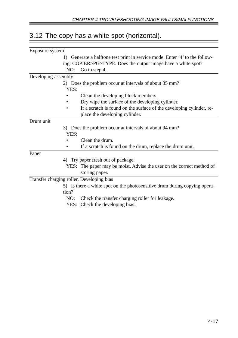
................................................. 4-163.12 The copy has a white spot (horizon-
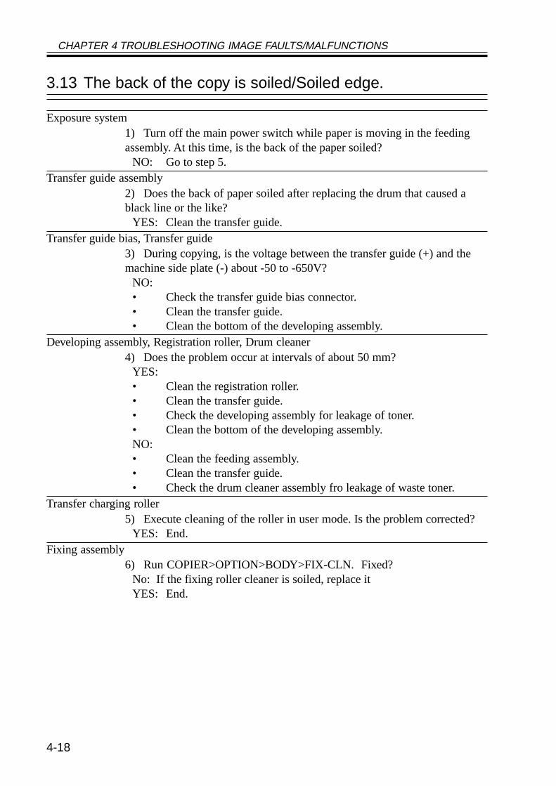
tal) ............................................ 4-173.13 The back of the copy is soiled/
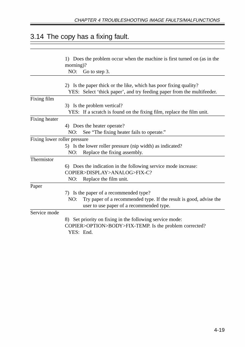
Soiled edge ............................... 4-183.14 The copy has a fixing fault ....... 4-193.15 The copy has a displaced leading
edge .......................................... 4-203.16 The copy has a displaced leading
edge (large margin) .................. 4-203.17 The copy has a displaced margin
(no margin) ............................... 4-203.18 The copy is blurred .................. 4-213.19 The copy is foggy (horizontal)
................................................. 4-223.20 The copy has inadequate sharpness
................................................. 4-233.21 The copy is completely blank
................................................. 4-243.22 The copy is completely black
................................................. 4-263.23 The copy has a block/white dot after
replacement of the drum unit................................................. 4-27
3.24 The copy has a black line (streamreading) .................................... 4-27
4 Troubleshooting Malfunctions ....... 4-284.1 Power Supply System .............. 4-28
4.1.1 The AC power is absent ..... 4-284.1.2 The DC power is absent
........................................... 4-294.2 Printer Unit .............................. 4-30
4.2.1 Pickup fails ........................ 4-30
4.2.2 The lifter fails to move up(pickup from the cassette)........................................... 4-31
4.2.3 The vertical path roller fails torotate .................................. 4-32
4.2.4 The registration roller fails torotate .................................. 4-32
4.2.5 Pickup from the multifeedertray fails (i.e., the pickup rollerfails to rotate) ..................... 4-33
4.2.6 Pickup from the multifeedertray fails (i.e., the multifeederholding plate fails to move up)........................................... 4-33
4.2.7 The photosensitive drum fails torotate .................................. 4-34
4.2.8 The pre-exposure lamp fails togo ON ................................ 4-34
4.3 Reader Unit .............................. 4-354.3.1 The No. 1 mirror base fails to
move .................................. 4-354.3.2 The scanning lamp fails to go
ON ..................................... 4-364.4 Message Indication .................. 4-37
4.4.1 The “Add Toner” message failsto go OFF ........................... 4-37
4.4.2 The “Control Card Set” mes-sage fails to go OFF (when nocard reader is installed) ...... 4-37
4.4.3 The “Add Paper” message failsto go OFF ........................... 4-37
4.4.4 The “Close the Front Cover”massage fails to go OFF..... 4-38
4.5 Paper Deck ............................... 4-394.5.1 Pickup fails ........................ 4-394.5.2 The deck lifter fails to move up
........................................... 4-405 Troubleshooting Feeding Faults...... 4-41
5.1 Paper Jams ............................... 4-415.1.1 Pickup Assembly ............... 4-425.1.2 Separation/Feeding Assembly
........................................... 4-435.1.3 Fixing/Delivery Assembly, Du-
plex Reversing Assembly........................................... 4-43
CONTENTS
1 Outline of Service Mode .................. 5-11.1 Outline ....................................... 5-11.2 Starting Service Mode and Making
Selections ................................... 5-21.3 Ending Service Mode................. 5-31.4 Backing Up Service Mode ......... 5-31.5 Using Service Mode ................... 5-4
1.5.1 Initial Screen ........................ 5-41.5.2 Level 1/Level 2 Item Screen
............................................. 5-41.5.3 Level 3 Item Screen ............. 5-5
2 DISPLAY Control Display Mode...... 5-62.1 COPIER ..................................... 5-62.2 FEEDER .................................. 5-19
3 I/O, I/O Display mode .................... 5-20
3.1 DC-CON .................................. 5-213.2 R-CON ..................................... 5-283.3 MN-CON ................................. 5-313.4 FEEDER .................................. 5-333.5 SORTER .................................. 5-35
3.5.1 Finisher-J1 ......................... 5-353.5.2 Saddle Finisher-G1 ............ 5-383.5.3 Puncher Unit (Saddle Finisher-
G1) ..................................... 5-414 ADJUST Adjustment Mode ........... 5-44
4.1 COPIER ................................... 5-444.2 FEEDER .................................. 5-584.3 SORTER .................................. 5-59
5 FUNCTION Operation/InspectionMode .............................................. 5-61
CHAPTER 5 SERVICE MODE
5.1.4 Duplex Feeding Assembly........................................... 4-44
5.2 Faulty Feeding ......................... 4-455.2.1 Double Feeding ................. 4-455.2.2 Wrinkles ............................ 4-45
6 Outline of Electrical Components........................................................ 4-46
6.1 Introduction .............................. 4-466.1.1 Guide to the List ................ 4-466.1.2 Checking the Photointerrupters
........................................... 4-476.2 E201 (reader unit/printer unit) . 4-48
6.2.1 Clutches ............................. 4-486.2.2 Solenoids, Switches ........... 4-486.2.3 Motors (1/2) ....................... 4-506.2.3 Motors (2/2) ....................... 4-526.2.4 Fans .................................... 4-546.2.5 Sensors (1/3) ...................... 4-566.2.5 Sensors (2/3) ...................... 4-586.2.5 Sensors (3/3) ...................... 4-606.2.6 Lamps, Heaters, and Others
........................................... 4-626.2.7 PCBs .................................. 4-64
6.3 Side Paper Deck-L1 ................. 4-666.3.1 Clutches ............................. 4-666.3.2 Solenoids, and Switches..... 4-66
6.3.3 Motors ................................ 4-666.3.4 Sensors ............................... 4-686.3.5 PCBs .................................. 4-68
6.4 2-Cassette Feeding Unit-W1................................................. 4-70
6.4.1 Clutches ............................. 4-706.4.2 Solenoids and Switches ..... 4-706.4.3 Motors ................................ 4-706.4.4 Sensors ............................... 4-726.4.5 PCBs .................................. 4-72
6.5 Inner 2-Way Tray-A1 ............... 4-746.5.1 Solenoids ........................... 4-746.5.2 Motors ................................ 4-746.5.3 Sensors ............................... 4-74
6.6 Super G3 FAX Board-J1 .......... 4-766.6.1 Others ................................ 4-766.6.2 PCBs .................................. 4-76
6.7 Variable Resistors (VR), Light-Emitting Diodes, and Check Pins byPCB .......................................... 4-78
6.7.1 Main Controller PCB ......... 4-796.7.2 DC Controller PCB............ 4-806.7.3 Reader Controller PCB ...... 4-806.7.4 Composite Power Supply PCB
........................................... 4-816.7.5 Fixing Film Sensor PCB
........................................... 4-81
CONTENTS
1 Self Diagnosis .................................. 6-11.1 Detail Codes (copier) ................. 6-31.2 ADF Error Codes ..................... 6-371.3 Saddle Finisher-G1 Error Codes
................................................. 6-38
1.3.1 Error Code of the Finisher Unit................................................. 6-38
1.4 Finisher-J1 Error Codes ........... 6-43
CHAPTER 6 SELF DIAGNOSIS
5.1 COPIER ................................... 5-616 OPTION Machine Settings Mode
........................................................ 5-816.1 COPIER ................................... 5-816.2 FEEDER .................................. 5-94
6.3 SORTER .................................. 5-946.4 BOARD.................................... 5-95
7 TEST Test Print Mode ................... 5-988 COUNTER Counter Mode ........... 5-100
CHAPTER 7 UPGRADING1 Upgrading ......................................... 7-1
1.1 Outline ....................................... 7-11.1.1 Download Mode .................. 7-11.1.2 Making Pre-Checks ............. 7-2
1.2 Data Control ............................... 7-51.3 Downloading the System Software,
RUI, and Language Module ....... 7-81.3.1 Making Connections ............ 7-81.3.2 Downloading ....................... 7-81.3.3 After Downloading ............ 7-14
1.4 Upgrading the BOOT ROM...... 7-141.4.1 Making Preparations .......... 7-141.4.2 Connection ......................... 7-151.4.3 Preparing BOOT ROM ...... 7-151.4.4 After Downloading ............ 7-19
1.5 Formatting the HDD ................ 7-201.5.1 Making Connections .......... 7-201.5.2 Starting Formatting ............ 7-20
1.5.3 Points to Note When Formattingthe Hard Disk ..................... 7-26
1.6 Downloader PCB ..................... 7-271.6.1 Purpose .............................. 7-271.6.2 Downloader PCB Components
........................................... 7-271.6.3 Download Procedure ......... 7-281.6.4 Disconnecting .................... 7-32
1.7 Upgrading by Replacing theDIMM/ROM ............................ 7-33
2 Backing Up Data ............................ 7-342.1 Outline ..................................... 7-342.2 Backing Up Data ...................... 7-35
2.2.1 Making Preparations .......... 7-352.2.2 Making Connections .......... 7-352.2.3 Backing Up Data ............... 7-362.2.4 Downloading Backup Data
........................................... 7-412.2.5 Managing Backup Data ..... 7-45
A. General Timing Chart ...................... A-1B. General Circuit Diagram ................. A-3C. Side Paper Deck-L1 General Circuit
Diagram ........................................... A-5D. 2-Cassette Feeding Unit-W1 General
Circuit Diagram ............................... A-6
E. Inner 2-Way Tray-A1 General CircuitDiagram ........................................... A-7
F. Specifications .................................. A-81 Main Body ................................ A-8
1.1 Type .................................... A-81.2 Systems ............................... A-8
APPENDIX

CONTENTS
1.3 Functions ............................ A-91.4 Others ............................... A-12
2 Side Paper Deck-L1 ................ A-152.1 Systems ............................. A-15
3 Cassette Feeding Unit-W1 ...... A-163.1 Systems ............................. A-16
4 Inner 2way Tray-A1 ................ A-174.1 Type .................................. A-17
5 Envelope Feeder Attachment-B1................................................ A-18
5.1 Systems ............................. A-185.2 Envelopes .......................... A-195.3 Guaranteed Image Area .... A-20
G. List of Special Tools ...................... A-21H. List of Solvents/Oils ...................... A-23
CHAPTER 1 MAINTENANCE AND INSPECTION
1-1
CHAPTER 1 MAINTENACE AND INSPECTION
1 Periodically Replaced Parts
Some of the parts used in the machine must be replaced on a periodical basis to ensure aspecific level of product performance; be sure to replace them as indicated, as they will af-fect the machine functions appreciably once they fail.
If possible, plan the replacement to coincide with a scheduled visit to the user’s.
The estimates are subject to change depending on the conditions of the siteof installation or how the machine is used.
1.1 Reader UnitThe reader unit does not have parts that require periodical replacement.
1.2 Printer UnitThe printer unit does not have parts that require periodical replacement.
1.3 Side Paper DeckThe side paper deck does not have parts that require periodical replacement.
1.4 Cassette Feeding unitThe cassette feeding unit does not have parts that require periodical replacement.
1.5 Inner 2-Way TrayThe inner 2-way tray does not have parts that require periodical replacement.
1
CHAPTER 1 MAINTENANCE AND INSPECTION
1-2
2 Consumables and Durables
Some parts of the machine may require replacement over the period of product warrantybecause of wear or damage. Replace them as needed.
2.1 Checking the Time of ReplacementUse service mode to find out when to replace a specific part:
COPIER>COUNTER>DRBL-2.
2.2 Reader UnitThe reader unit does not have parts designated as a durable.
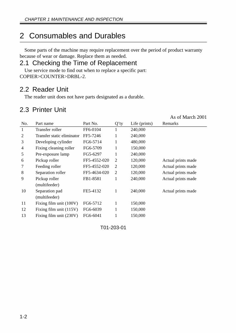
2.3 Printer UnitAs of March 2001
No. Part name Part No. Q’ty Life (prints) Remarks1 Transfer roller FF6-0104 1 240,0002 Transfer static eliminatorFF5-7246 1 240,0003 Developing cylinder FG6-5714 1 480,0004 Fixing cleaning roller FG6-5709 1 150,0005 Pre-exposure lamp FG5-6297 1 240,0006 Pickup roller FF5-4552-020 2 120,000 Actual prints made7 Feeding roller FF5-4552-020 2 120,000 Actual prints made8 Separation roller FF5-4634-020 2 120,000 Actual prints made9 Pickup roller FB1-8581 1 240,000 Actual prints made
(multifeeder)10 Separation pad FE5-4132 1 240,000 Actual prints made
(multifeeder)11 Fixing film unit (100V) FG6-5712 1 150,00012 Fixing film unit (115V) FG6-6039 1 150,00013 Fixing film unit (230V) FG6-6041 1 150,000
T01-203-01
CHAPTER 1 MAINTENANCE AND INSPECTION
1-3
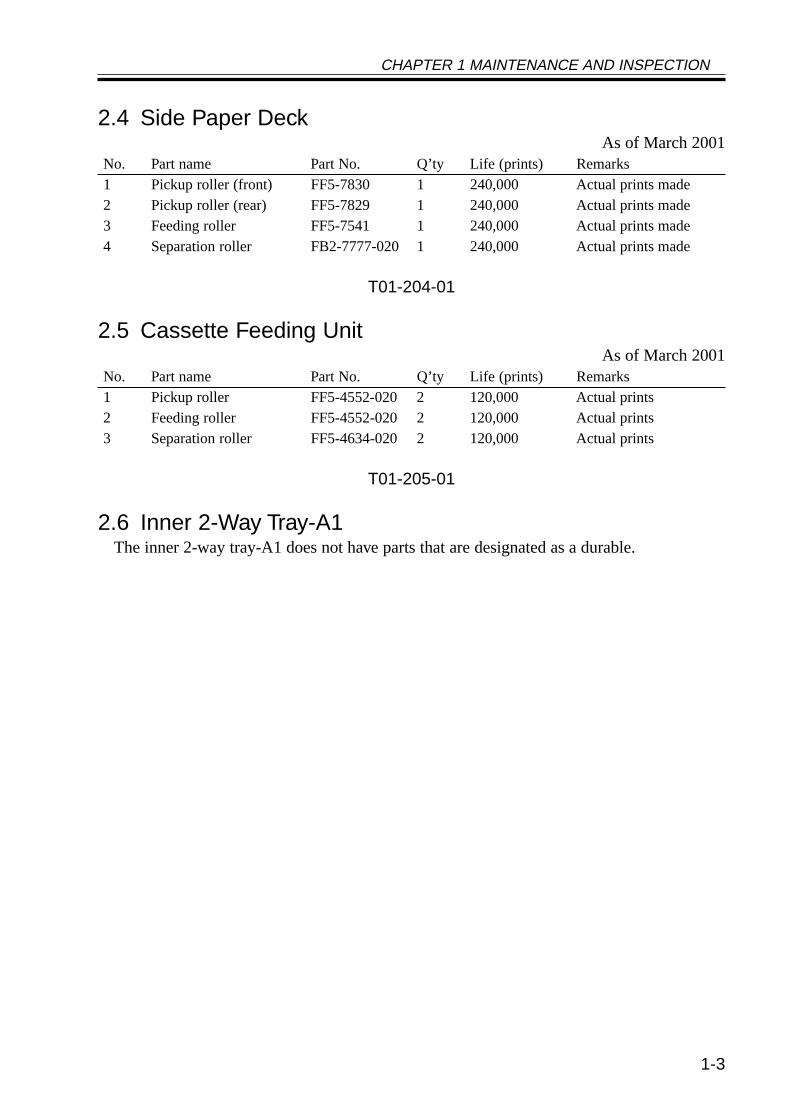
2.4 Side Paper DeckAs of March 2001
No. Part name Part No. Q’ty Life (prints) Remarks1 Pickup roller (front) FF5-7830 1 240,000 Actual prints made2 Pickup roller (rear) FF5-7829 1 240,000 Actual prints made3 Feeding roller FF5-7541 1 240,000 Actual prints made4 Separation roller FB2-7777-020 1 240,000 Actual prints made
T01-204-01
2.5 Cassette Feeding UnitAs of March 2001
No. Part name Part No. Q’ty Life (prints) Remarks1 Pickup roller FF5-4552-020 2 120,000 Actual prints2 Feeding roller FF5-4552-020 2 120,000 Actual prints3 Separation roller FF5-4634-020 2 120,000 Actual prints
T01-205-01
2.6 Inner 2-Way Tray-A1The inner 2-way tray-A1 does not have parts that are designated as a durable.
CHAPTER 1 MAINTENANCE AND INSPECTION
1-4
3 Periodical Servicing Procedure
1. As a rule, provide periodical servicing every 120,000 prints.2. Before setting out on a scheduled visit, check the Service Book, and
take any parts that may require replacement.
As of June 2001Work Procedure
1. Report to the person in charge, and check the general condition.2. Record the counter reading, and check the faulty prints.3. Make test prints, and check them for the following: (1) image density, (2) white back-
ground for soiling, (3) characters for clarity, (4) margin, (5) fixing, registration, and backfor soiling.The margin must meet the following standards:
Leading edge: 2.5 ± 1.5 mmLeft edge: 2.5 ± 1.5 mmRight edge: 0.5 mm or moreTrailing edge: 2.5 +1.1, -1.7 mm (smaller than B4) <2.5 ± 2.0 mm>
3.5 +0.6, -2.8 mm (B4 or larger) <3.5 ± 2.0 mm>5.5 +1.5, -5.0 mm (free size)
< >: when the DADF-H1 picks up an original(in stream readig mode).
4. Optical UnitClean the following using a blower brush to clean; if the dirt is excessive, use alcohol:(1) No. 1/2/3 mirror, (2) original illuminating reflecting plate, (3) lens, (4) original size
sensor.5. Scanner Drive System
(1) Scanner cable; check the tension, and adjust as necessary. Inspect and adjust the scan-ner cable only when the machine has made the first 250,000 prints.
(2) Scanner rail; clean the slide area, and apply silicone oil (FY9-6011).
CHAPTER 1 MAINTENANCE AND INSPECTION
1-5
6. Feeding SystemClean the following: (1) feeding assembly base, (2) fixing inlet guide (upper, lower), (3)transfer guide, (4) pre-registration assembly (paper lint).
7. Image Formation SystemClean the following: developing member, (2) developing assembly bottom.
8. Optical UnitClean the following with a special tool: (1) bending mirror.
9. Image Formation SystemInspect and, as necessary, remove the waste toner and then clean the waste toner case;or, replace the waste toner case if any:
1. Be sure to dispose of the water toner according to the standards im-posed by the government concerned.
2. Do not dispose of waste toner into fire (to avoid explosion).
10. Make test copies.11. Make sample copies.12. Check the operation of the leakage breaker.
While the power switch is ON, press the test switch of the leakage breaker to make surethat it operates normally (i.e., the lever goes OFF to cut the power).If the leakage breaker fails to operate normally, replace it and make a check once again.To reset,After making a check, turn off the main power switch (the lever should go ON), and thenturn on the main power switch.
13. Put the sample copies into order, and clean up the area around the machine.14. Fill out the Service Book, and report to the person in charge; put a description of the
check made on the operation of the leakage breaker in the Service Book.
CHAPTER 1 MAINTENANCE AND INSPECTION
1-6
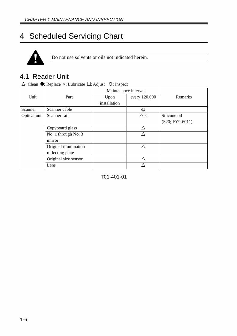
4 Scheduled Servicing Chart
Do not use solvents or oils not indicated herein.
4.1 Reader Unit: Clean : Replace ×: Lubricate : Adjust : Inspect
T01-401-01
Part
Scanner cableScanner rail
Copyboard glassNo. 1 through No. 3mirrorOriginal illuminationreflecting plateOriginal size sensorLens
Unit
ScannerOptical unit
Uponinstallation
Maintenance intervalsRemarks
Silicone oil(S20; FY9-6011)
every 120,000
×
CHAPTER 1 MAINTENANCE AND INSPECTION
1-7
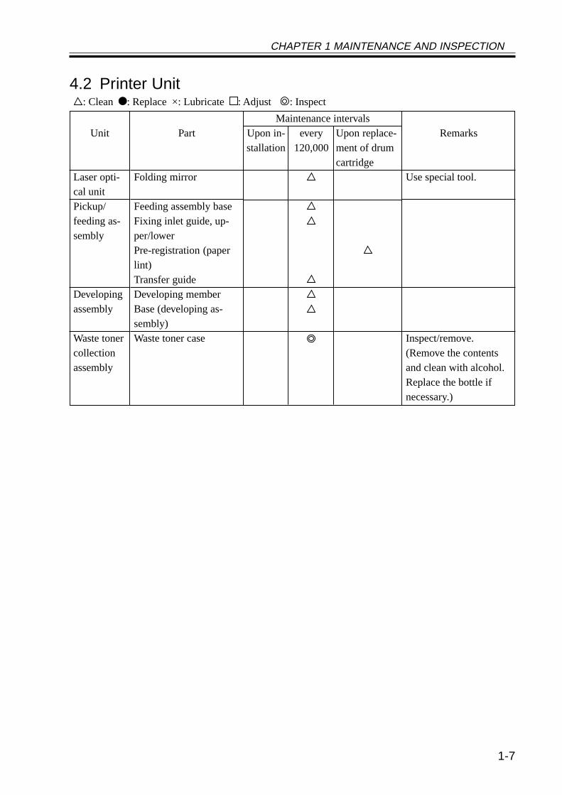
4.2 Printer Unit: Clean : Replace ×: Lubricate : Adjust : Inspect
Part
Folding mirror
Feeding assembly baseFixing inlet guide, up-per/lowerPre-registration (paperlint)Transfer guideDeveloping memberBase (developing as-sembly)Waste toner case
Unit
Laser opti-cal unitPickup/feeding as-sembly
Developingassembly
Waste tonercollectionassembly
Upon in-stallation
every120,000
Maintenance intervalsRemarks
Use special tool.
Inspect/remove.(Remove the contentsand clean with alcohol.Replace the bottle ifnecessary.)
Upon replace-ment of drumcartridge
CHAPTER 1 MAINTENANCE AND INSPECTION
1-8
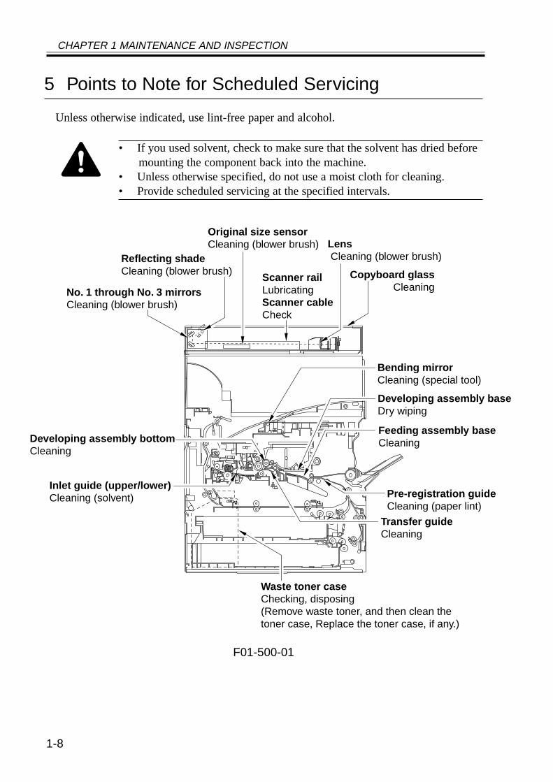
5 Points to Note for Scheduled Servicing
Unless otherwise indicated, use lint-free paper and alcohol.
• If you used solvent, check to make sure that the solvent has dried beforemounting the component back into the machine.
• Unless otherwise specified, do not use a moist cloth for cleaning.• Provide scheduled servicing at the specified intervals.
F01-500-01
No. 1 through No. 3 mirrorsCleaning (blower brush)
Reflecting shadeCleaning (blower brush) Copyboard glass
Cleaning
Original size sensorCleaning (blower brush)
Scanner railLubricatingScanner cableCheck
Lens Cleaning (blower brush)
Bending mirrorCleaning (special tool)
Feeding assembly base Cleaning
Developing assembly base Dry wiping
Transfer guideCleaning
Developing assembly bottomCleaning
Waste toner caseChecking, disposing(Remove waste toner, and then clean thetoner case, Replace the toner case, if any.)
Inlet guide (upper/lower) Cleaning (solvent) Pre-registration guide
Cleaning (paper lint)
CHAPTER 1 MAINTENANCE AND INSPECTION
1-9
6 Cleaning the Bottom of the Developing Assembly
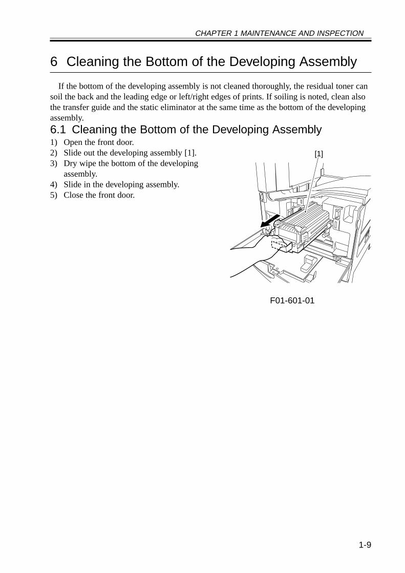
If the bottom of the developing assembly is not cleaned thoroughly, the residual toner cansoil the back and the leading edge or left/right edges of prints. If soiling is noted, clean alsothe transfer guide and the static eliminator at the same time as the bottom of the developingassembly.
6.1 Cleaning the Bottom of the Developing Assembly1) Open the front door.2) Slide out the developing assembly [1].3) Dry wipe the bottom of the developing
assembly.4) Slide in the developing assembly.5) Close the front door.
F01-601-01
[1]

2-1
CHAPTER 2 IMAGE ADJUSTMENT BASIC PROCEDURE
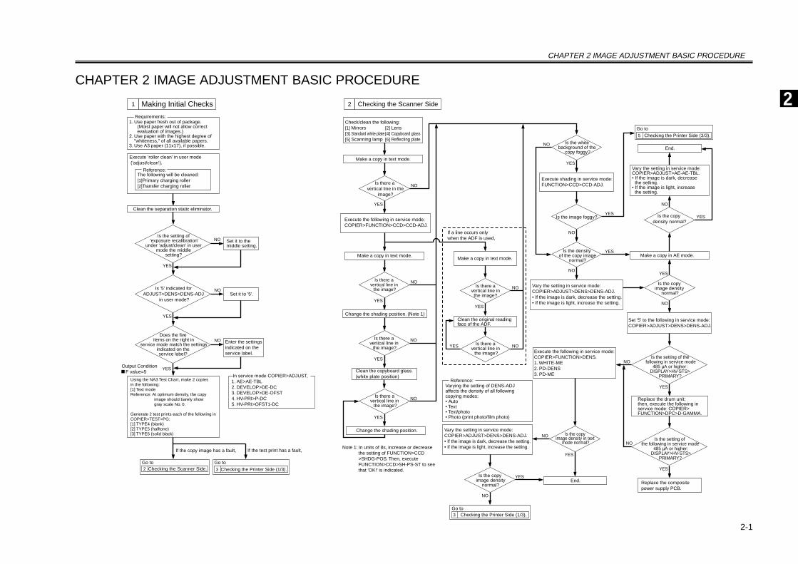
Execute the following in service mode: COPIER>FUNCTION>CCD>CCD-ADJ.
Check/clean the following:[1] Mirrors [2] Lens[3] Standard white plate [4] Copyboard glass[5] Scanning lamp [6] Reflecting plate
Make a copy in text mode.
YES
Is there a vertical line in the
image?
YES
YES
YES
NO
NO
NO
Make a copy in text mode.
Change the shading position. (Note 1)
Change the shading position.
Clean the copyboard glass. (white plate position)
Is there a vertical line in
the image?
Is there a vertical line in
the image?
Is there a vertical line in
the image?
YES
YES
YES
YES
NO
NO
NO
NO
Is the copy image density
normal?
Execute the following in service mode: COPIER>FUNCTION>DENS.1. WHITE-ME2. PD-DENS3. PD-ME
Is the setting of the following in service mode
485 µA or higher: DISPLAY>HV-STS>
PRIMARY?
Is the setting of the following in service mode
485 µA or higher: DISPLAY>HV-STS>
PRIMARY?
Replace the drum unit; then, execute the following in service mode: COPIER> FUNCTION>DPC>D-GAMMA.
Is the copy image density in text
mode normal?
Reference:Varying the setting of DENS-ADJ affects the density of all following copying modes:• Auto• Text• Text/photo• Photo (print photo/film photo)
Vary the setting in service mode: COPIER>ADJUST>DENS>DENS-ADJ.• If the image is dark, decrease the setting.• If the image is light, increase the setting.
3 Checking the Printer Side (1/3).
5 Checking the Printer Side (3/3).
Replace the composite power supply PCB.
End.
Set '5' to the following in service mode: COPIER>ADJUST>DENS>DENS-ADJ.
NO
NO
NO
NO
NO
YES
YES
Execute shading in service mode: FUNCTION>CCD>CCD-ADJ.
Vary the setting in service mode: COPIER>ADJUST>AE-AE-TBL.• If the image is dark, decrease
the setting.• If the image is light, increase
the setting.
End.
Make a copy in AE mode.YES
YES
YES
Is the white background of the
copy foggy?
Is the copy density normal?
Vary the setting in service mode: COPIER>ADJUST>DENS>DENS-ADJ.• If the image is dark, decrease the setting.• If the image is light, increase the setting.
Is the copy image density
normal?
Is the density of the copy image
normal?
Is the image foggy?
NO
NO
NO
Is there a vertical line in
the image?
YES
Make a copy in text mode.
Is there avertical line in the image?
YES
If a line occurs only when the ADF is used,
Clean the original reading face of the ADF.
Note 1: In units of 8s, increase or decreasethe setting of FUNCTION>CCD>SHDG-POS. Then, execute FUNCTION>CCD>SH-PS-ST to see that 'OK!' is indicated.
Output Condition F value=5
If the copy image has a fault, If the test print has a fault,
1. Use paper fresh out of package. (Moist paper will not allow correct evaluation of images.)
2. Use paper with the highest degree of "whiteness," of all available papers.
3. Use A3 paper (11x17), if possible.
Requirements:
Execute 'roller clean' in user mode ('adjust/clean').
The following will be cleaned:[1]Primary charging roller[2]Transfer charging roller
Reference:
Using the NA3 Test Chart, make 2 copies in the following:[1] Text modeReference: At optimum density, the copy
image should barely show gray scale No. 0.
Generate 2 test prints each of the following in COPIER>TEST>PG:[1] TYPE4 (blank)[2] TYPE5 (halftone)[3] TYPE6 (solid black)
Clean the separation static eliminator.
Does the five items on the right in
service mode match the settings indicated on the
service label?
Enter the settingsindicated on theservice label.
Set it to '5'.
Set it to the middle setting.
Is the setting of 'exposure recalibration'
under 'adjust/clean' in usermode the middle
setting?
Is '5' indicated for ADJUST>DENS>DENS-ADJ
in user mode?
2 Checking the Scanner Side. 3 Checking the Printer Side (1/3).
NO
NO
YES
NO
YES
YES
In service mode COPIER>ADJUST,1. AE>AE-TBL2. DEVELOP>DE-DC3. DEVELOP>DE-OFST4. HV-PRI>P-DC5. HV-PRI>OFST1-DC
1 Making Initial Checks 2 Checking the Scanner Side
Go to Go to
Go to
Go to
2CHAPTER 2 IMAGE ADJUSTMENT BASIC PROCEDURE
2-2
CHAPTER 2 IMAGE ADJUSTMENT BASIC PROCEDURE
YES
NO
NO
NO
NO
NO
NO
NO
NO
NO
NO
Is there a vertical line in
the image?
YES
YES
YES
YES
YES
YES
YES
YES
YES
Is there a vertical line in
the image?
Is there ea vertical line in the
image?
Is the setting of the following in service mode 485 µA:
DISPLAY>HV-STS>PRIMARY?
Replace the composite power supply PCB.
Is there a vertical line on the
surface of the sleeve?
NO
NO
YES
NO
NO
NO NO
NO
NOYES
YES
YES
YES
Is there a line on the surface
of the sleeve?
Clean the following:[1] Laser mirror[2] No. 1 mirror
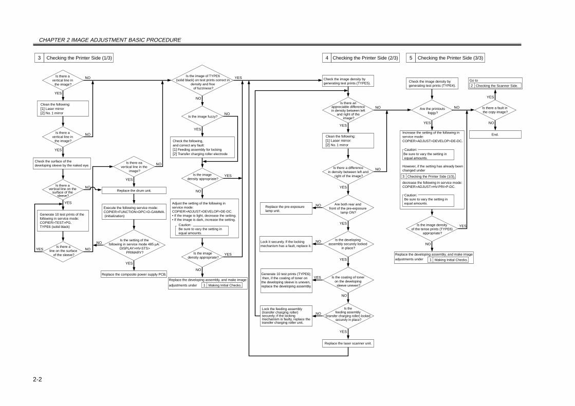
Generate 10 test prints of the following in service mode: COPIER>TEST>PG.TYPE6 (solid black)
Check the surface of the developing sleeve by the naked eye.
Replace the drum unit.
Execute the following service mode: COPIER>FUNCTION>DPC>D-GAMMA. (initialization)
Is the image of TYPE6 (solid black) on test prints correct in
density and free of fuzziness?
Is the image fuzzy?
Is the image density appropriate?
Is the image density appropriate?
Check the following, and correct any fault:[1] Feeding assembly for locking[2] Transfer charging roller electrode
Adjust the setting of the following in service mode: COPIER>ADJUST>DEVELOP>DE-DC.• If the image is light, decrease the setting.• If the image is dark, increase the setting.
Caution:Be sure to vary the setting in equal amounts.
Check the image density by generating test prints (TYPE5).
Is there an appreciable difference in density between left
and right of the image?
YES
Clean the following:[1] Laser mirror:[2] No. 1 mirror
Are both rear and front of the pre-exposure
lamp ON?
Is there a difference in density between left and
right of the image?
YES
YES
NO
YES
Is the developing assembly securely locked
in place?
Is the coating of toner on the developing
sleeve uneven?
Replace the pre-exposure lamp unit.
Lock it securely. If the locking mechanism has a fault, replace it.
Generate 10 test prints (TYPE6); then, if the coating of toner on the developing sleeve is uneven, replace the developing assembly.
Is the feeding assembly
(transfer charging roller) locked securely in place?
Lock the feeding assembly (transfer charging roller) securely; if the locking mechanism is faulty, replace the transfer charging roller unit.
Replace the laser scanner unit.
Check the image density by generating test prints (TYPE4).
Are the printouts foggy?
Is the image density of the tense prints (TYPE6)
appropriate?
Is there a fault in the copy image?
2 Checking the Scanner Side.
End.
1 Making Initial Checks.
Increase the setting of the following in service mode: COPIER>ADJUST>DEVELOP>DE-DC.
Caution: Be sure to vary the setting in equal amounts.
However, if the setting has already been changed under
3 Checking the Printer Side (1/3),
decrease the following in service mode: COPIER>ADJUST>HV-PRI>P-DC.
Caution: Be sure to vary the setting in equal amounts.
3 Checking the Printer Side (1/3) 4 Checking the Printer Side (2/3) 5 Checking the Printer Side (3/3)
1 Making Initial Checks.
Replace the developing assembly, and make image adjustments under
Replace the developing assembly, and make image
adjustments under
Go to
CHAPTER 3 STANDARDS AND ADJUSTMENTS
3-1
CHAPTER 3 STANDARDS AND ADJUSTMENTS
1 Image Adjustments
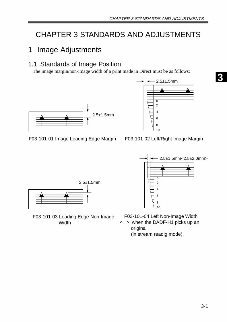
1.1 Standards of Image PositionThe image margin/non-image width of a print made in Direct must be as follows:
F03-101-01 Image Leading Edge Margin F03-101-02 Left/Right Image Margin
F03-101-04 Left Non-Image Width< >: when the DADF-H1 picks up an
original(in stream readig mode).
F03-101-03 Leading Edge Non-ImageWidth
2.5±1.5mm
02
4
6
8
10
2.5±1.5mm
2.5±1.5mm<2.5±2.0mm>
02
4
6
8
10
2.5±1.5mm
3
CHAPTER 3 STANDARDS AND ADJUSTMENTS
3-2
1.2 Checking the Image PositionMake prints using the following as the source of paper (10 prints each), and check to see
that the image margin and the non-image width are as indicated:• Each cassette• Manual feed tray• Duplex feeding unit• Side paper deck
If not as indicated, adjust the image position in the following order:1. Adjusting the left/right image margin (registration)2. Adjusting the image leading edge margin (registration)3. Adjusting the left/right non-image width (CCD read start position)4. Leading edge non-image width (scanner image leading edge position)
CHAPTER 3 STANDARDS AND ADJUSTMENTS
3-3
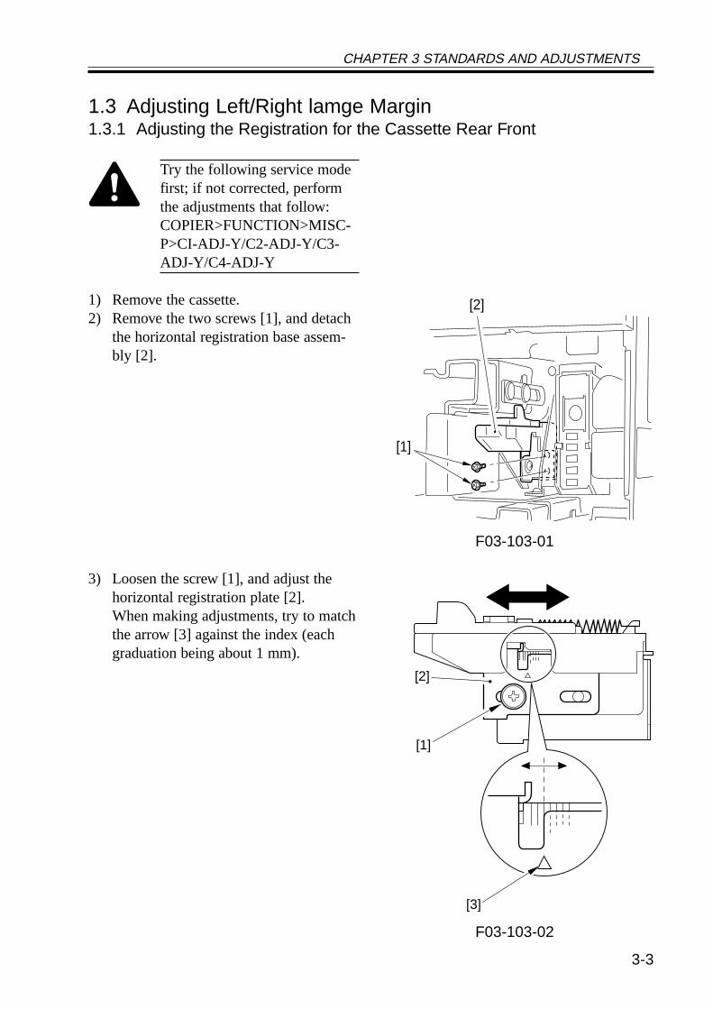
1.3 Adjusting Left/Right lamge Margin1.3.1 Adjusting the Registration for the Cassette Rear Front
Try the following service modefirst; if not corrected, performthe adjustments that follow:COPIER>FUNCTION>MISC-P>CI-ADJ-Y/C2-ADJ-Y/C3-ADJ-Y/C4-ADJ-Y
1) Remove the cassette.2) Remove the two screws [1], and detach
the horizontal registration base assem-bly [2].
F03-103-01
3) Loosen the screw [1], and adjust thehorizontal registration plate [2].When making adjustments, try to matchthe arrow [3] against the index (eachgraduation being about 1 mm).
F03-103-02
[1]
[2]
[2]
[1]
[3]
CHAPTER 3 STANDARDS AND ADJUSTMENTS
3-4
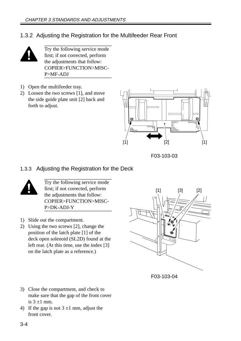
1.3.2 Adjusting the Registration for the Multifeeder Rear Front
Try the following service modefirst; if not corrected, performthe adjustments that follow:COPIER>FUNCTION>MISC-P>MF-ADJ
1) Open the multifeeder tray.2) Loosen the two screws [1], and move
the side guide plate unit [2] back andforth to adjust.
F03-103-03
1.3.3 Adjusting the Registration for the Deck
Try the following service modefirst; if not corrected, performthe adjustments that follow:COPIER>FUNCTION>MISC-P>DK-ADJ-Y
1) Slide out the compartment.2) Using the two screws [2], change the
position of the latch plate [1] of thedeck open solenoid (SL2D) found at theleft rear. (At this time, use the index [3]on the latch plate as a reference.)
F03-103-04
3) Close the compartment, and check tomake sure that the gap of the front coveris 3 ±1 mm.
4) If the gap is not 3 ±1 mm, adjust thefront cover.
[2] [1][1]
[1] [3] [2]
CHAPTER 3 STANDARDS AND ADJUSTMENTS
3-5
1.3.4 Duplex Feeding Unit1) Adjust the image margin as indicated using service mode: COPIER>ADJUST>FEED-
ADJ>ADJ-REFE.
1.4 Adjusting the Image Leading Edge Margin1) Adjust the image margin in service mode so that it is as indicated:
COPIER>ADJUST>FEED-ADJ>REGIST.
F03-104-01
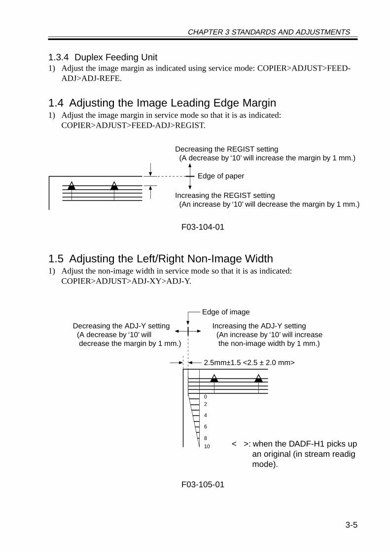
1.5 Adjusting the Left/Right Non-Image Width1) Adjust the non-image width in service mode so that it is as indicated:
COPIER>ADJUST>ADJ-XY>ADJ-Y.
< >: when the DADF-H1 picks upan original (in stream readigmode).
F03-105-01
Edge of paper
Decreasing the REGIST setting (A decrease by ‘10’ will increase the margin by 1 mm.)
Increasing the REGIST setting (An increase by ‘10’ will decrease the margin by 1 mm.)
2.5mm±1.5 <2.5 ± 2.0 mm>
Edge of image
Increasing the ADJ-Y setting (An increase by ‘10’ will increase the non-image width by 1 mm.)
Decreasing the ADJ-Y setting (A decrease by ‘10’ will
decrease the margin by 1 mm.)
02
4
6
8
10
CHAPTER 3 STANDARDS AND ADJUSTMENTS
3-6
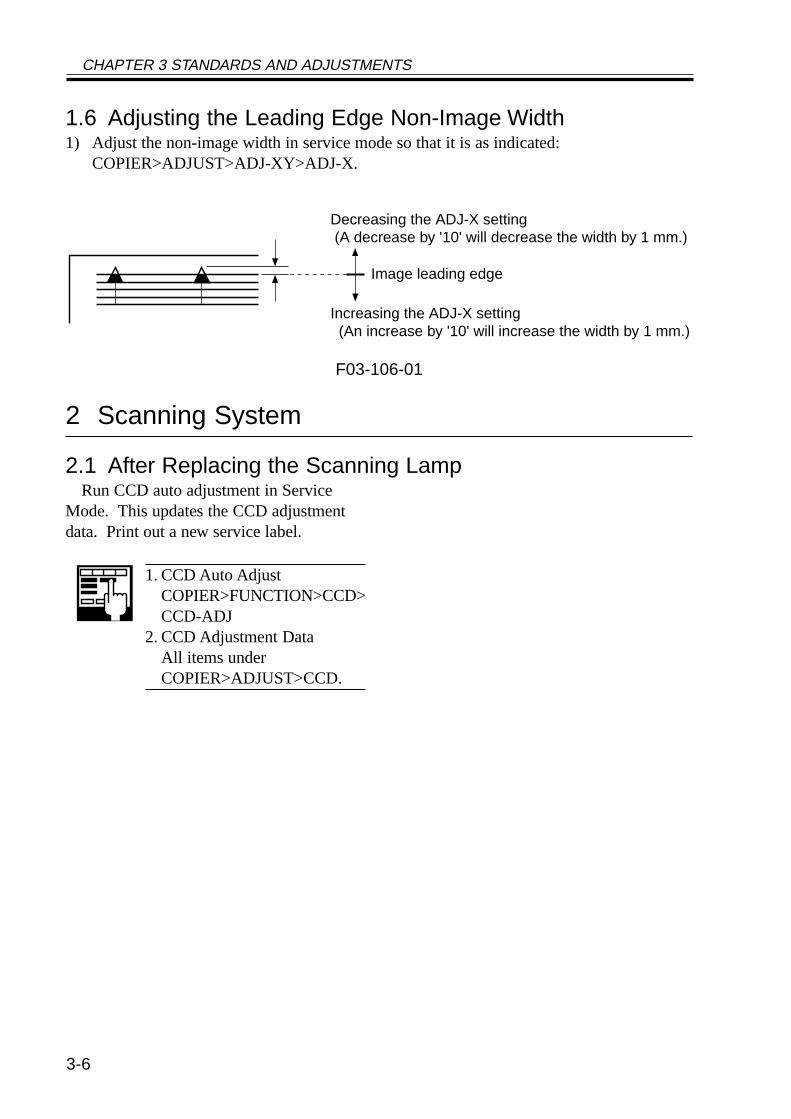
1.6 Adjusting the Leading Edge Non-Image Width1) Adjust the non-image width in service mode so that it is as indicated:
COPIER>ADJUST>ADJ-XY>ADJ-X.
F03-106-01
2 Scanning System
2.1 After Replacing the Scanning LampRun CCD auto adjustment in Service
Mode. This updates the CCD adjustmentdata. Print out a new service label.
1. CCD Auto AdjustCOPIER>FUNCTION>CCD>CCD-ADJ
2. CCD Adjustment DataAll items underCOPIER>ADJUST>CCD.
Image leading edge
Decreasing the ADJ-X setting(A decrease by '10' will decrease the width by 1 mm.)
Increasing the ADJ-X setting (An increase by '10' will increase the width by 1 mm.)
CHAPTER 3 STANDARDS AND ADJUSTMENTS
3-7
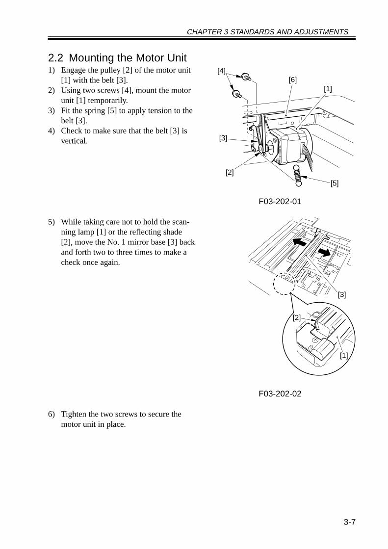
2.2 Mounting the Motor Unit1) Engage the pulley [2] of the motor unit
[1] with the belt [3].2) Using two screws [4], mount the motor
unit [1] temporarily.3) Fit the spring [5] to apply tension to the
belt [3].4) Check to make sure that the belt [3] is
vertical.
F03-202-01
5) While taking care not to hold the scan-ning lamp [1] or the reflecting shade[2], move the No. 1 mirror base [3] backand forth two to three times to make acheck once again.
F03-202-02
6) Tighten the two screws to secure themotor unit in place.
[1][6]
[2]
[3]
[4]
[5]
[3]
[1]
[2]
CHAPTER 3 STANDARDS AND ADJUSTMENTS
3-8
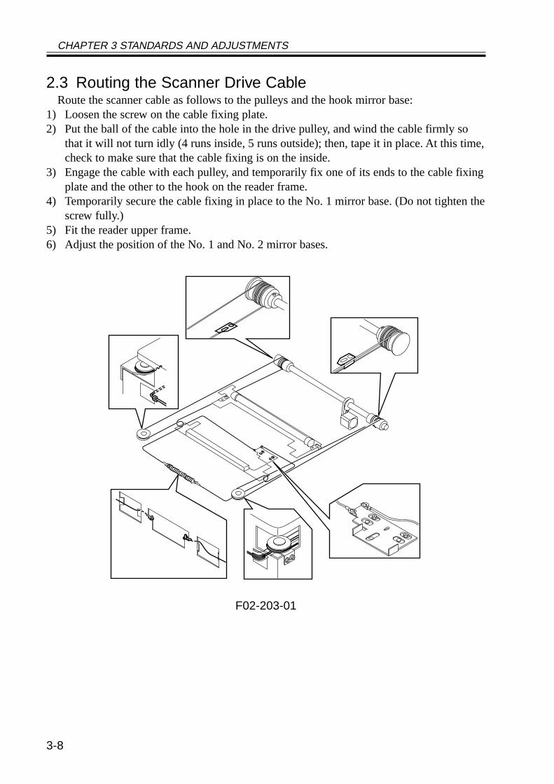
2.3 Routing the Scanner Drive CableRoute the scanner cable as follows to the pulleys and the hook mirror base:
1) Loosen the screw on the cable fixing plate.2) Put the ball of the cable into the hole in the drive pulley, and wind the cable firmly so
that it will not turn idly (4 runs inside, 5 runs outside); then, tape it in place. At this time,check to make sure that the cable fixing is on the inside.
3) Engage the cable with each pulley, and temporarily fix one of its ends to the cable fixingplate and the other to the hook on the reader frame.
4) Temporarily secure the cable fixing in place to the No. 1 mirror base. (Do not tighten thescrew fully.)
5) Fit the reader upper frame.6) Adjust the position of the No. 1 and No. 2 mirror bases.
F02-203-01
CHAPTER 3 STANDARDS AND ADJUSTMENTS
3-9
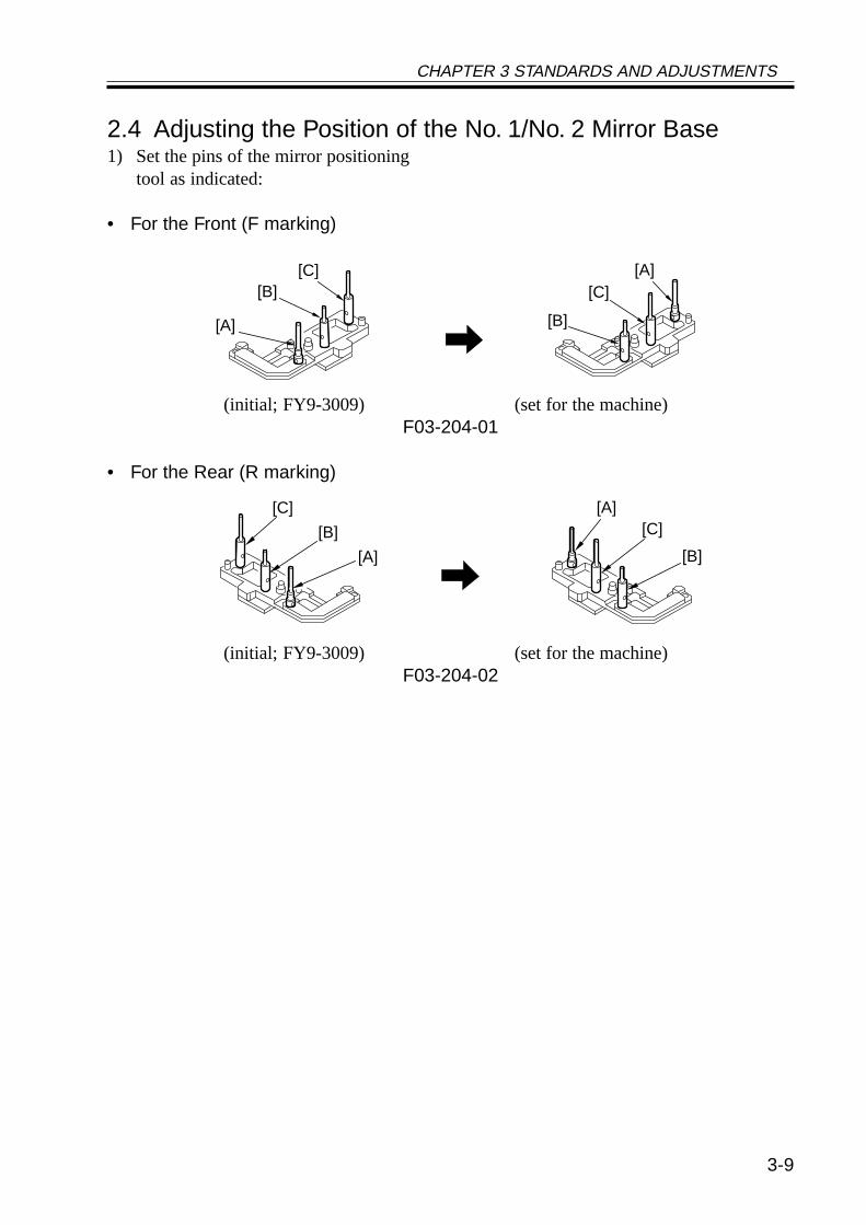
2.4 Adjusting the Position of the No. 1/No. 2 Mirror Base1) Set the pins of the mirror positioning
tool as indicated:
• For the Front (F marking)
(initial; FY9-3009) (set for the machine)F03-204-01
• For the Rear (R marking)
(initial; FY9-3009) (set for the machine)F03-204-02
[A]
[A][B]
[B]
[C][C]
[A]
[A]
[B]
[B]
[C][C]
CHAPTER 3 STANDARDS AND ADJUSTMENTS
3-10
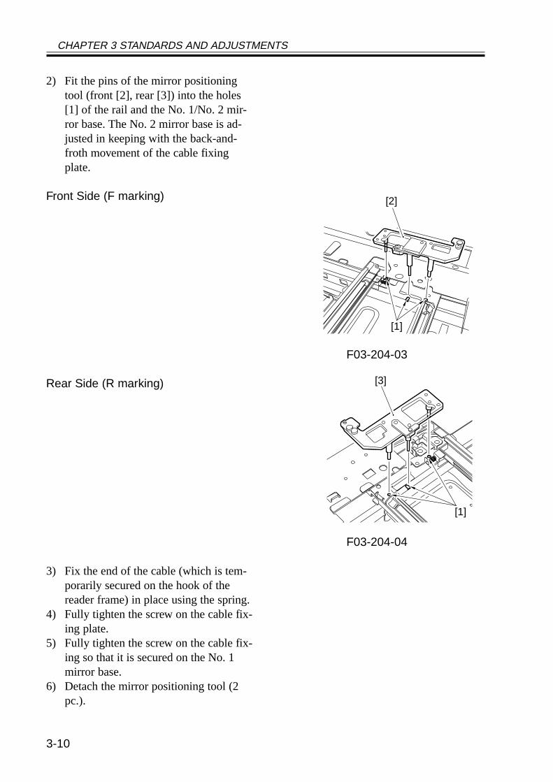
2) Fit the pins of the mirror positioningtool (front [2], rear [3]) into the holes[1] of the rail and the No. 1/No. 2 mir-ror base. The No. 2 mirror base is ad-justed in keeping with the back-and-froth movement of the cable fixingplate.
Front Side (F marking)
F03-204-03
Rear Side (R marking)
F03-204-04
3) Fix the end of the cable (which is tem-porarily secured on the hook of thereader frame) in place using the spring.
4) Fully tighten the screw on the cable fix-ing plate.
5) Fully tighten the screw on the cable fix-ing so that it is secured on the No. 1mirror base.
6) Detach the mirror positioning tool (2pc.).
[2]
[1]
[3]
[1]
CHAPTER 3 STANDARDS AND ADJUSTMENTS
3-11
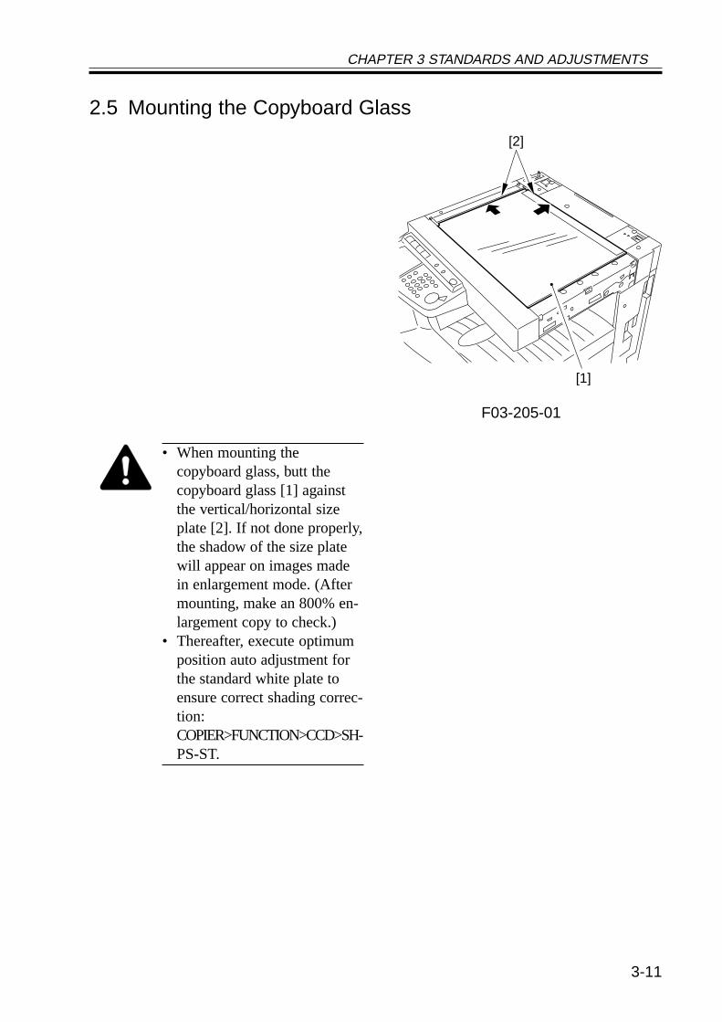
2.5 Mounting the Copyboard Glass
F03-205-01
• When mounting thecopyboard glass, butt thecopyboard glass [1] againstthe vertical/horizontal sizeplate [2]. If not done properly,the shadow of the size platewill appear on images madein enlargement mode. (Aftermounting, make an 800% en-largement copy to check.)
• Thereafter, execute optimumposition auto adjustment forthe standard white plate toensure correct shading correc-tion:COPIER>FUNCTION>CCD>SH-PS-ST.
[2]
[1]
CHAPTER 3 STANDARDS AND ADJUSTMENTS
3-12
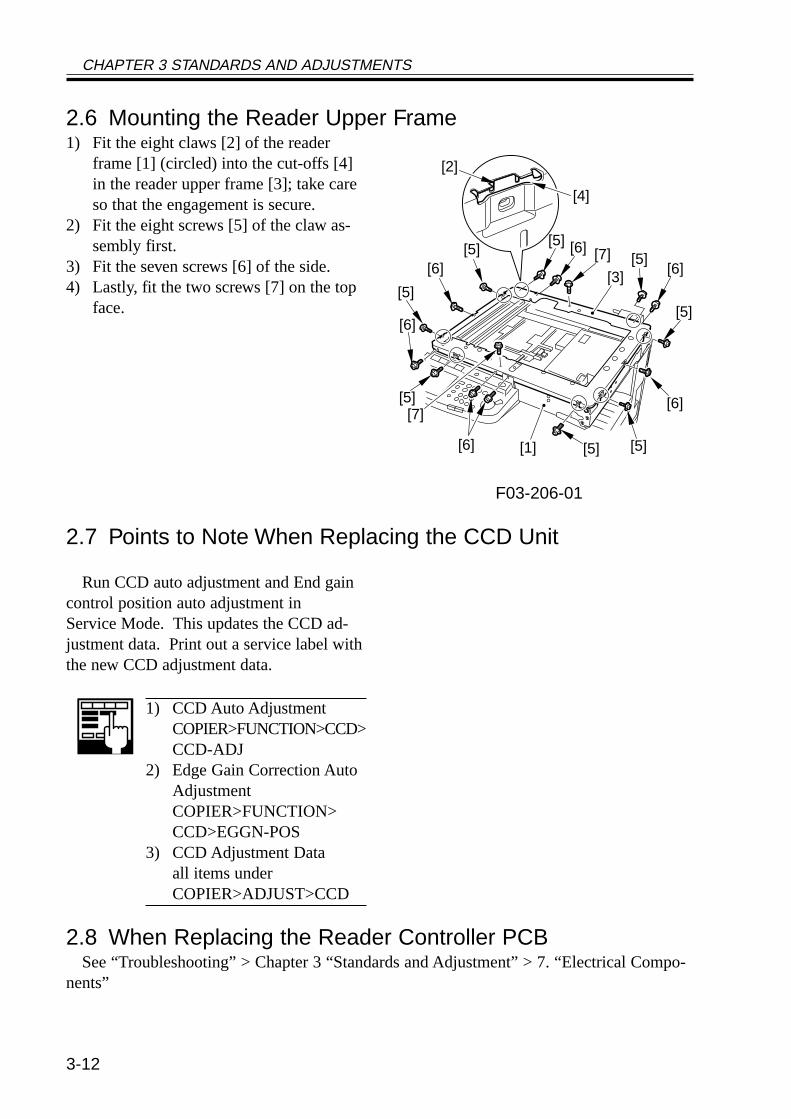
2.6 Mounting the Reader Upper Frame1) Fit the eight claws [2] of the reader
frame [1] (circled) into the cut-offs [4]in the reader upper frame [3]; take careso that the engagement is secure.
2) Fit the eight screws [5] of the claw as-sembly first.
3) Fit the seven screws [6] of the side.4) Lastly, fit the two screws [7] on the top
face.
F03-206-01
2.7 Points to Note When Replacing the CCD Unit
Run CCD auto adjustment and End gaincontrol position auto adjustment inService Mode. This updates the CCD ad-justment data. Print out a service label withthe new CCD adjustment data.
1) CCD Auto AdjustmentCOPIER>FUNCTION>CCD>CCD-ADJ
2) Edge Gain Correction AutoAdjustmentCOPIER>FUNCTION>CCD>EGGN-POS
3) CCD Adjustment Dataall items underCOPIER>ADJUST>CCD
2.8 When Replacing the Reader Controller PCBSee “Troubleshooting” > Chapter 3 “Standards and Adjustment” > 7. “Electrical Compo-
nents”
[4]
[2]
[7]
[7]
[5] [6]
[5]
[6][5]
[5]
[6]
[6] [5]
[6]
[6]
[5]
[5][3]
[1] [5]
CHAPTER 3 STANDARDS AND ADJUSTMENTS
3-13
3 Image Formation System
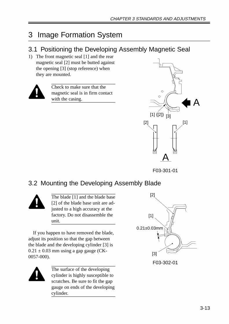
3.1 Positioning the Developing Assembly Magnetic Seal1) The front magnetic seal [1] and the rear
magnetic seal [2] must be butted againstthe opening [3] (stop reference) whenthey are mounted.
Check to make sure that themagnetic seal is in firm contactwith the casing.
F03-301-01
3.2 Mounting the Developing Assembly Blade
The blade [1] and the blade base[2] of the blade base unit are ad-justed to a high accuracy at thefactory. Do not disassemble theunit.
If you happen to have removed the blade,adjust its position so that the gap betweenthe blade and the developing cylinder [3] is0.21 ± 0.03 mm using a gap gauge (CK-0057-000).
F03-302-01The surface of the developingcylinder is highly susceptible toscratches. Be sure to fit the gapgauge on ends of the developingcylinder.
A
A
[1][2]
[3][1] ([2])
[1]
[2]
[3]
0.21±0.03mm
CHAPTER 3 STANDARDS AND ADJUSTMENTS
3-14
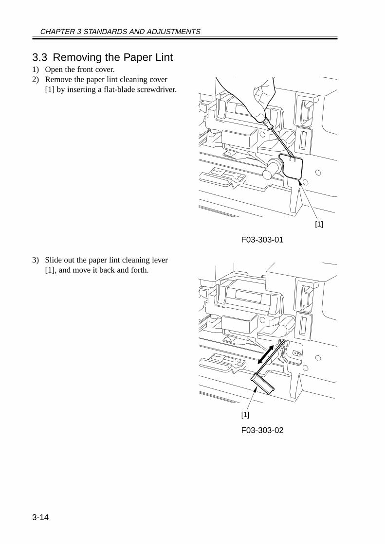
3.3 Removing the Paper Lint1) Open the front cover.2) Remove the paper lint cleaning cover
[1] by inserting a flat-blade screwdriver.
F03-303-01
3) Slide out the paper lint cleaning lever[1], and move it back and forth.
F03-303-02
[1]
[1]
CHAPTER 3 STANDARDS AND ADJUSTMENTS
3-15
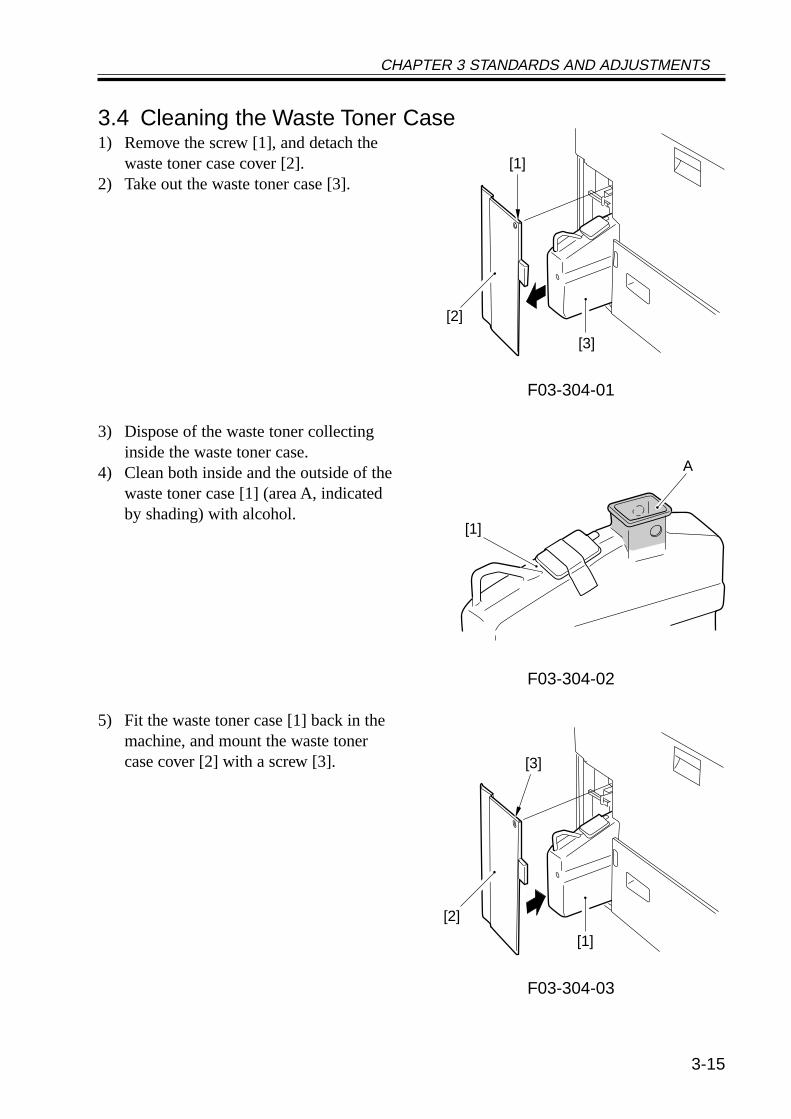
3.4 Cleaning the Waste Toner Case1) Remove the screw [1], and detach the
waste toner case cover [2].2) Take out the waste toner case [3].
F03-304-01
3) Dispose of the waste toner collectinginside the waste toner case.
4) Clean both inside and the outside of thewaste toner case [1] (area A, indicatedby shading) with alcohol.
F03-304-02
5) Fit the waste toner case [1] back in themachine, and mount the waste tonercase cover [2] with a screw [3].
F03-304-03
[1]
[2]
[3]
[1]
A
[3]
[2]
[1]
CHAPTER 3 STANDARDS AND ADJUSTMENTS
3-16
4 Fixing System
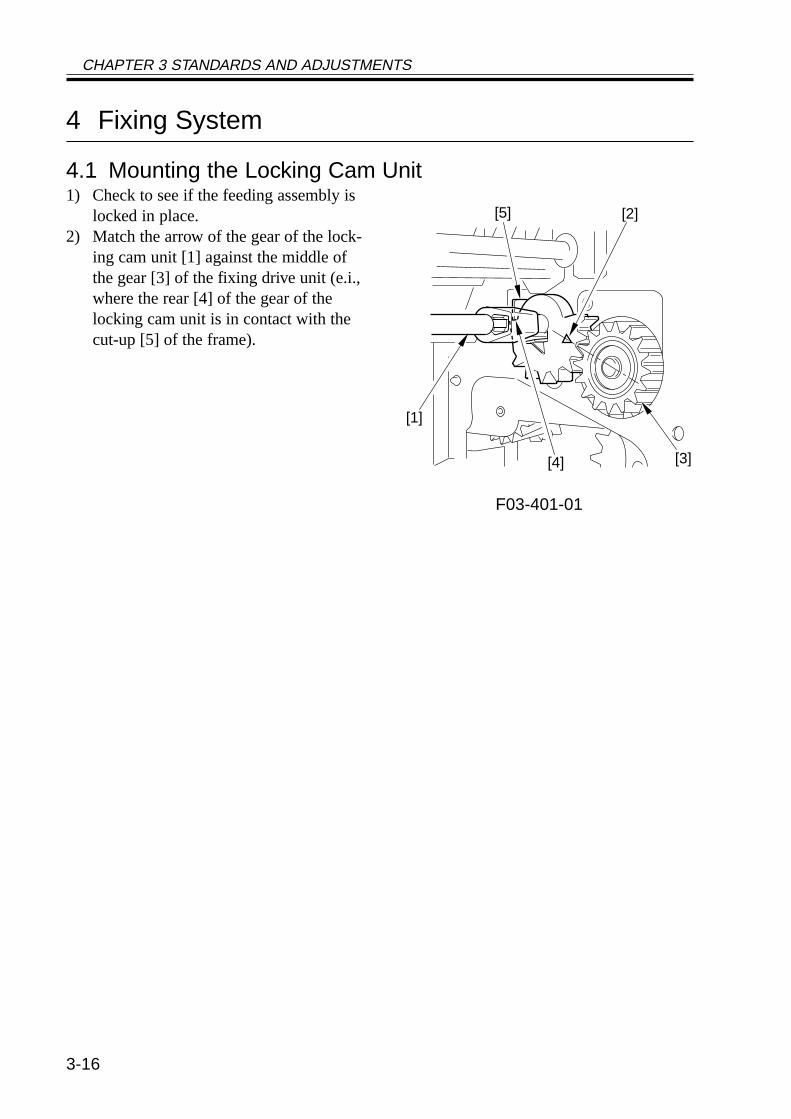
4.1 Mounting the Locking Cam Unit1) Check to see if the feeding assembly is
locked in place.2) Match the arrow of the gear of the lock-
ing cam unit [1] against the middle ofthe gear [3] of the fixing drive unit (e.i.,where the rear [4] of the gear of thelocking cam unit is in contact with thecut-up [5] of the frame).
F03-401-01
[4] [3]
[1]
[5] [2]
CHAPTER 3 STANDARDS AND ADJUSTMENTS
3-17
5 Paper Deck
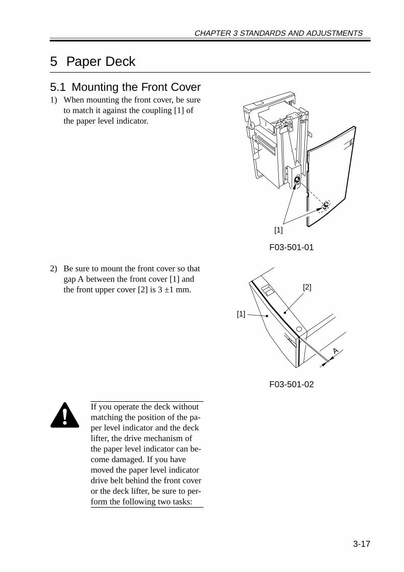
5.1 Mounting the Front Cover1) When mounting the front cover, be sure
to match it against the coupling [1] ofthe paper level indicator.
F03-501-01
2) Be sure to mount the front cover so thatgap A between the front cover [1] andthe front upper cover [2] is 3 ±1 mm.
F03-501-02
If you operate the deck withoutmatching the position of the pa-per level indicator and the decklifter, the drive mechanism ofthe paper level indicator can be-come damaged. If you havemoved the paper level indicatordrive belt behind the front coveror the deck lifter, be sure to per-form the following two tasks:
[1]
[1]
[2]
A
CHAPTER 3 STANDARDS AND ADJUSTMENTS
3-18
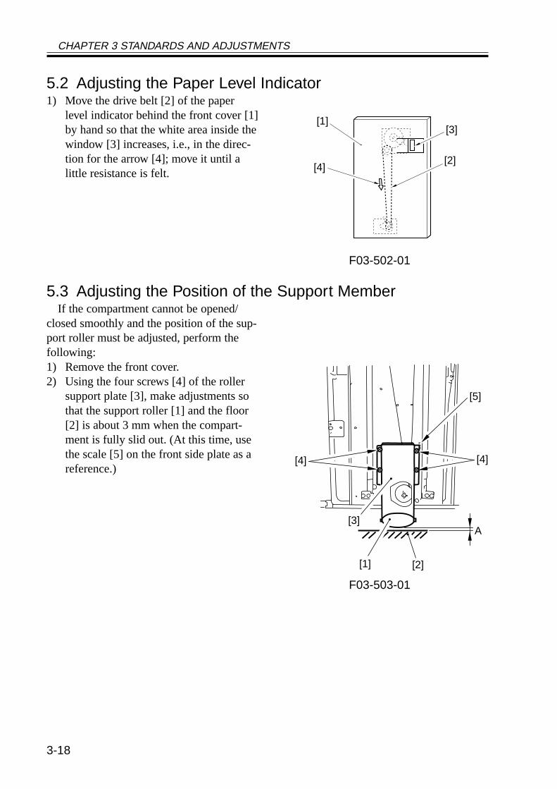
5.2 Adjusting the Paper Level Indicator1) Move the drive belt [2] of the paper
level indicator behind the front cover [1]by hand so that the white area inside thewindow [3] increases, i.e., in the direc-tion for the arrow [4]; move it until alittle resistance is felt.
F03-502-01
5.3 Adjusting the Position of the Support MemberIf the compartment cannot be opened/
closed smoothly and the position of the sup-port roller must be adjusted, perform thefollowing:1) Remove the front cover.2) Using the four screws [4] of the roller
support plate [3], make adjustments sothat the support roller [1] and the floor[2] is about 3 mm when the compart-ment is fully slid out. (At this time, usethe scale [5] on the front side plate as areference.)
F03-503-01
[1]
[2]
[3]
[4]
[4]
[5]
[2][1]
[3]A
[4]
CHAPTER 3 STANDARDS AND ADJUSTMENTS
3-19
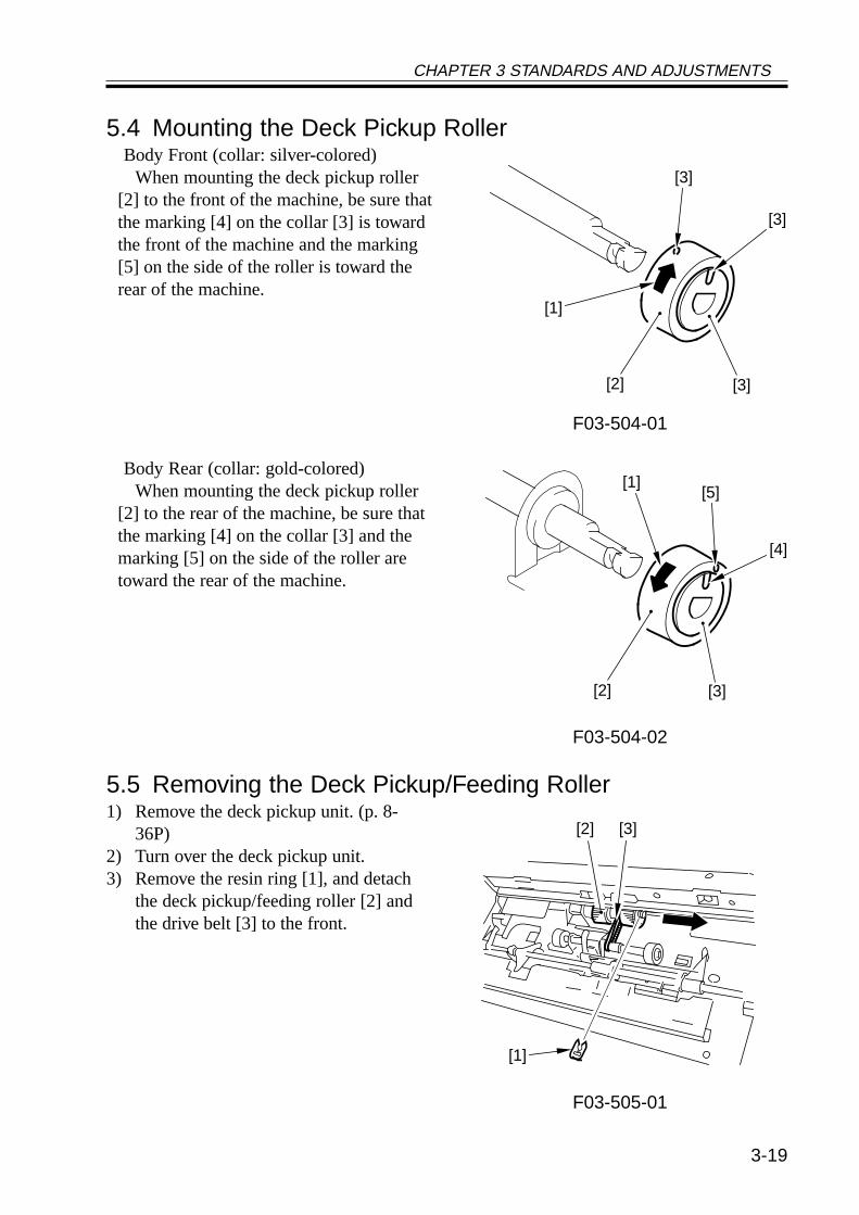
5.4 Mounting the Deck Pickup RollerBody Front (collar: silver-colored)
When mounting the deck pickup roller[2] to the front of the machine, be sure thatthe marking [4] on the collar [3] is towardthe front of the machine and the marking[5] on the side of the roller is toward therear of the machine.
F03-504-01
Body Rear (collar: gold-colored)When mounting the deck pickup roller
[2] to the rear of the machine, be sure thatthe marking [4] on the collar [3] and themarking [5] on the side of the roller aretoward the rear of the machine.
F03-504-02
5.5 Removing the Deck Pickup/Feeding Roller1) Remove the deck pickup unit. (p. 8-
36P)2) Turn over the deck pickup unit.3) Remove the resin ring [1], and detach
the deck pickup/feeding roller [2] andthe drive belt [3] to the front.
F03-505-01
[2] [3]
[3]
[3]
[1]
[4]
[5][1]
[2] [3]
[2] [3]
[1]
CHAPTER 3 STANDARDS AND ADJUSTMENTS
3-20
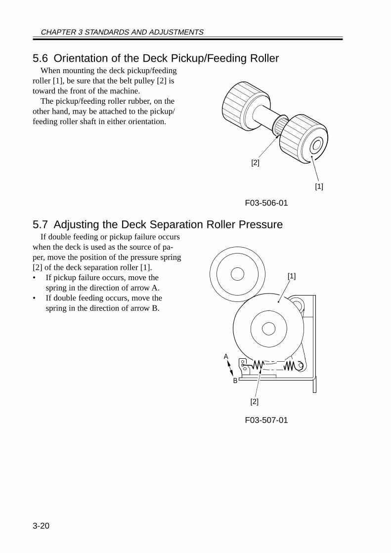
5.6 Orientation of the Deck Pickup/Feeding RollerWhen mounting the deck pickup/feeding
roller [1], be sure that the belt pulley [2] istoward the front of the machine.
The pickup/feeding roller rubber, on theother hand, may be attached to the pickup/feeding roller shaft in either orientation.
F03-506-01
5.7 Adjusting the Deck Separation Roller PressureIf double feeding or pickup failure occurs
when the deck is used as the source of pa-per, move the position of the pressure spring[2] of the deck separation roller [1].• If pickup failure occurs, move the
spring in the direction of arrow A.• If double feeding occurs, move the
spring in the direction of arrow B.
F03-507-01
[1]
[2]
A
B
[1]
[2]
CHAPTER 3 STANDARDS AND ADJUSTMENTS
3-21
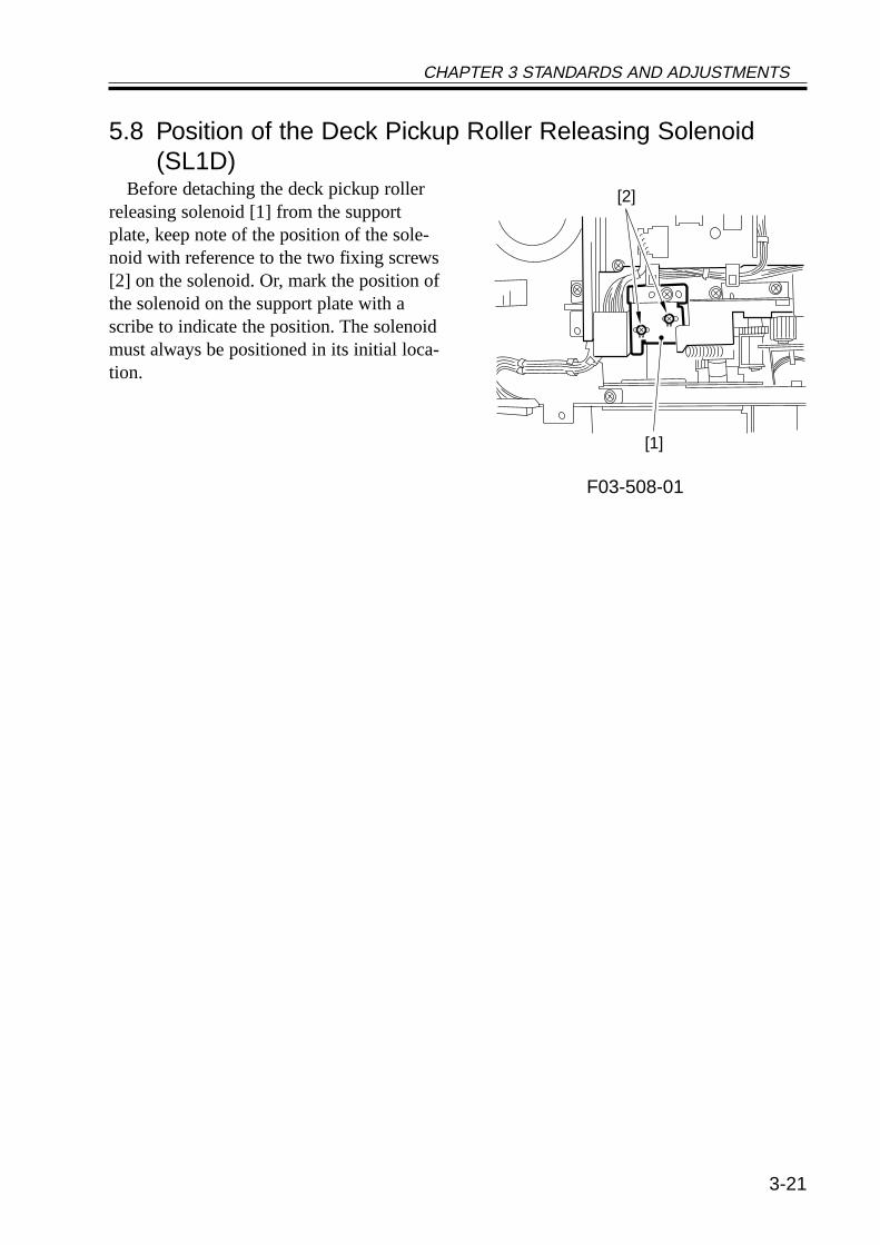
5.8 Position of the Deck Pickup Roller Releasing Solenoid(SL1D)
Before detaching the deck pickup rollerreleasing solenoid [1] from the supportplate, keep note of the position of the sole-noid with reference to the two fixing screws[2] on the solenoid. Or, mark the position ofthe solenoid on the support plate with ascribe to indicate the position. The solenoidmust always be positioned in its initial loca-tion.
F03-508-01
[1]
[2]
CHAPTER 3 STANDARDS AND ADJUSTMENTS
3-22
5.9 Adjusting the Height of the Side Member5.9.1 Before Making Adjustments1) Disconnect the machine from its host
machine, and then connect it once gain,thereby finding out whether the impactof connection causes the host machineto slide over or the machine to wobble.If any such problem is noted, adjust theheight of the side member as follows;otherwise, these steps need not be per-formed:
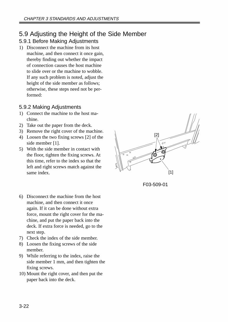
5.9.2 Making Adjustments1) Connect the machine to the host ma-
chine.2) Take out the paper from the deck.3) Remove the right cover of the machine.4) Loosen the two fixing screws [2] of the
side member [1].5) With the side member in contact with
the floor, tighten the fixing screws. Atthis time, refer to the index so that theleft and right screws match against thesame index.
F03-509-01
6) Disconnect the machine from the hostmachine, and then connect it onceagain. If it can be done without extraforce, mount the right cover for the ma-chine, and put the paper back into thedeck. If extra force is needed, go to thenext step.
7) Check the index of the side member.8) Loosen the fixing screws of the side
member.9) While referring to the index, raise the
side member 1 mm, and then tighten thefixing screws.
10) Mount the right cover, and then put thepaper back into the deck.
[1]
[2]

CHAPTER 3 STANDARDS AND ADJUSTMENTS
3-23
6 Cassette Feeding Unit-W1
6.1 Mounting the Pedestal Main Motor1) When mounting the pedestal main mo-
tor, be sure to tighten the screws in theorder indicated in the figure: (1) through(4).
F03-601-01
(1) (4)
(2)(3)
CHAPTER 3 STANDARDS AND ADJUSTMENTS
3-24
7 Envelope Feeder Attachment
7.1 Envelopes and Type of Spring• Use the green-painted spring for COM10, Monarch, DL, and YOUKEI 4.• Use the red-painted spring for C5 and B5.
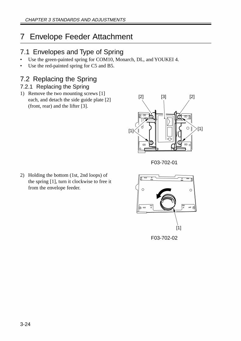
7.2 Replacing the Spring7.2.1 Replacing the Spring1) Remove the two mounting screws [1]
each, and detach the side guide plate [2](front, rear) and the lifter [3].
F03-702-01
2) Holding the bottom (1st, 2nd loops) ofthe spring [1], turn it clockwise to free itfrom the envelope feeder.
F03-702-02
[2] [3] [2]
[1] [1]
[1]
CHAPTER 3 STANDARDS AND ADJUSTMENTS
3-25
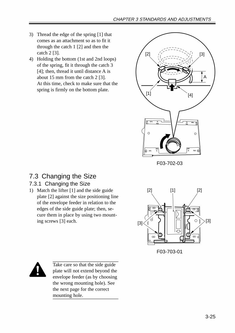
3) Thread the edge of the spring [1] thatcomes as an attachment so as to fit itthrough the catch 1 [2] and then thecatch 2 [3].
4) Holding the bottom (1st and 2nd loops)of the spring, fit it through the catch 3[4]; then, thread it until distance A isabout 15 mm from the catch 2 [3].At this time, check to make sure that thespring is firmly on the bottom plate.
F03-702-03
7.3 Changing the Size7.3.1 Changing the Size1) Match the lifter [1] and the side guide
plate [2] against the size positioning lineof the envelope feeder in relation to theedges of the side guide plate; then, se-cure them in place by using two mount-ing screws [3] each.
F03-703-01
Take care so that the side guideplate will not extend beyond theenvelope feeder (as by choosingthe wrong mounting hole). Seethe next page for the correctmounting hole.
A
[2]
[1]
[3]
[4]
[3] [3]
[2] [1] [2]
CHAPTER 3 STANDARDS AND ADJUSTMENTS
3-26
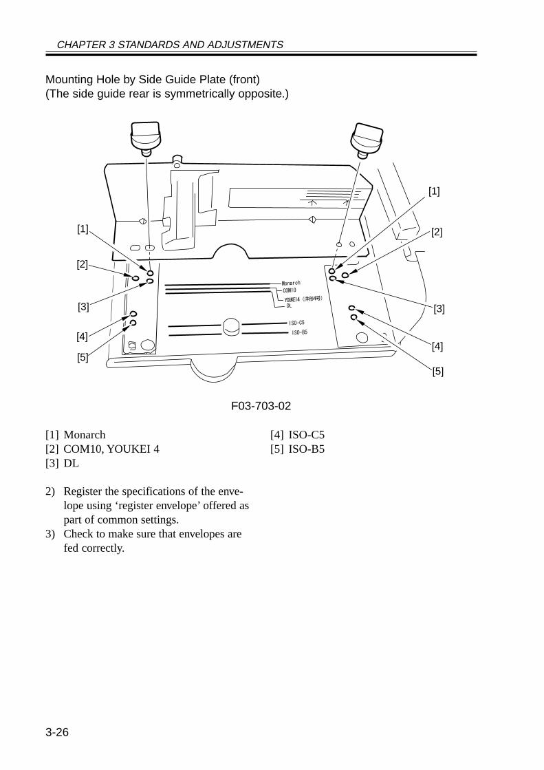
Mounting Hole by Side Guide Plate (front)(The side guide rear is symmetrically opposite.)
F03-703-02
2) Register the specifications of the enve-lope using ‘register envelope’ offered aspart of common settings.
3) Check to make sure that envelopes arefed correctly.
[1] Monarch[2] COM10, YOUKEI 4[3] DL
[4] ISO-C5[5] ISO-B5
[3]
[4]
[5]
[2]
[1]
[3]
[4]
[5]
[2]
[1]
CHAPTER 4 TROUBLESHOOTING IMAGE FAULTS/MALFUNCTIONS
4-1
CHAPTER 4 TROUBLESHOOTINGIMAGE FAULTS/MALFUNCTIONS
1 Making Initial Checks
1.1 Checking the Site of Installation1. There must be a source of power rated as indicated (rated voltage ± 10%). The source
must be exclusively of the machine, and the power plug must remain connected through-out the night.
2. The machine must not be in a high-temperature/-humidity area (near a water faucet, wa-ter boiler, humidifier), must not be cold or subject to dust. There must not be a source offire nearby.
3. The machine must not be subjected to ammonium gas.4. The machine must not be subjected to the direct rays of the sun; as necessary, curtains
must be provided.5. The room must be well ventilated.6. The floor must be flat to keep the machine level.7. The source of power must provide power night and day.
Check the sight against the above requirements.
1.2 Checking the OriginalsCheck to find out if the symptom is caused by the originals used or by the machine:
1. The copy density is optimum if set to index 5 ± 1.2. Originals with a reddish tone tend to prevent reproduction of good contrast.3. Originals of specific densities can produce copies that can be mistaken as faulty.
Memo
• An original with a reddish tint can produce copies with poor contrast.• Diazo copies used as originals or originals with a high degree of trans-
parency can produce copies that can be mistaken as “light copies.”• Originals prepared in pencil or with a greenish tint can produce copies
that can be mistaken as “light copies.”
1.3 Checking the ADF Platen, Copyboard cover, andCopyboard glass (standard white plate)
If the ADF platen, copyboard cover, or copyboard glass is soiled, clean it with a solutionof mild detergent; if scratched, replace it.
4
CHAPTER 4 TROUBLESHOOTING IMAGE FAULTS/MALFUNCTIONS
4-2
1.4 Charging Roller and Static Eliminator1. Check the transfer charging roller and the separation static eliminator for dirt and a fault
(damage).2. Check to make sure that the transfer charging roller and the separation static eliminator
are correctly mounted.
1.5 Checking the Developing Assembly1. Check to make sure that the members on both ends of the drum are in contact. Other-
wise, light images can result.2. Check to see the surface of the developing cylinder is coated with an even layer of toner.
Otherwise, light images or uneven density can result.
1.6 Checking the Paper1. Check to see if the paper used is of a recommended type. Advise the user that paper not
of a recommended type may fail to bring about expected results.2. Check to see if the paper is moist. Moist paper can adversely affect transfer, causing
poor images or separation faults (leading to jams and wrinkles). Advise the user on thecorrect method of storing paper.
1.7 Checking the Periodically Replaced PartsCheck with the scheduled servicing chart and the table of periodically replaced parts. Re-
place parts that have reached the ends of their lives.
1.8 Image Adjustment Basic ProcedureIf the copies have uneven density (difference between front and rear), light images, or
foggy background, try the Image Adjustment Basic Procedure first to see if the problem iscorrected.

CHAPTER 4 TROUBLESHOOTING IMAGE FAULTS/MALFUNCTIONS
4-3
1.9 OthersIn winter, bringing a machine from a cold to warm place can cause condensation inside
the machine, causing various problems.
Memo
1. Condensation in the optical system (glass, mirror, lens) can cause darkimages.
2. Condensation in the charging system can cause leakage.3. Condensation on the pickup/feeding guide can cause feeding faults.
If condensation is noted, dry wipe the part, or leave the machine pow-ered and alone for 60 min.

CHAPTER 4 TROUBLESHOOTING IMAGE FAULTS/MALFUNCTIONS
4-4
Blank Page

4-6
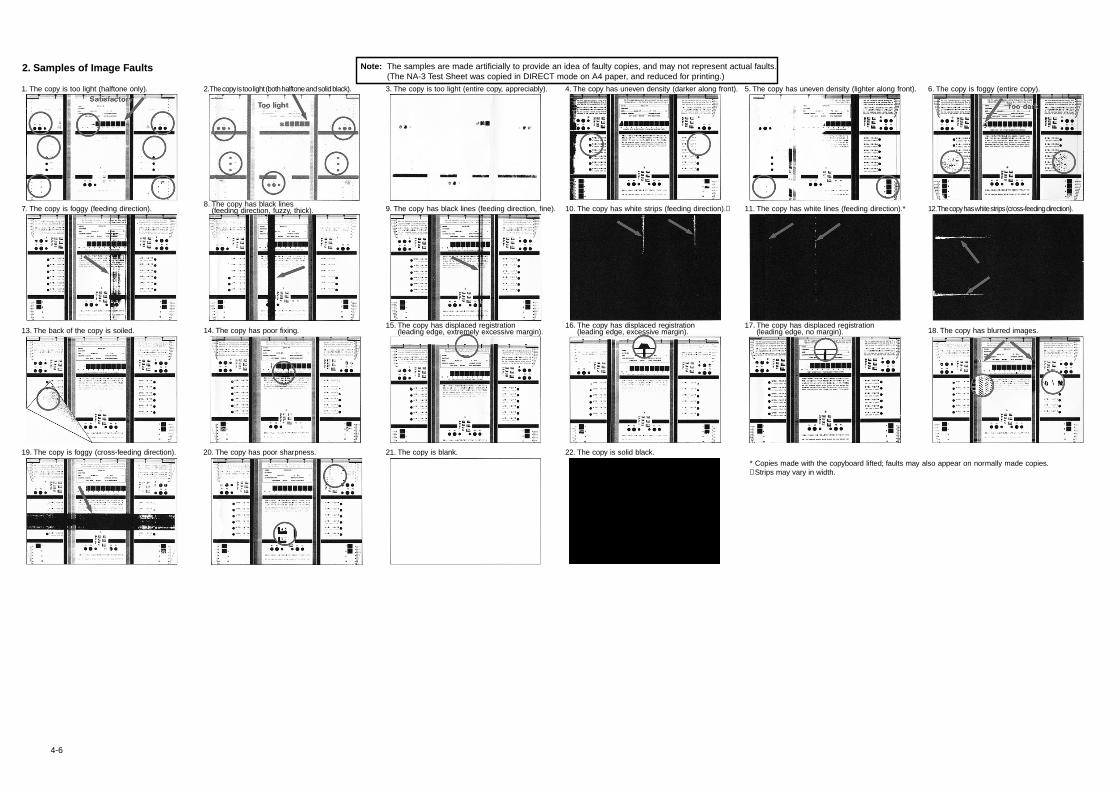
2. Samples of Image Faults
1. The copy is too light (halftone only).
7. The copy is foggy (feeding direction).
13. The back of the copy is soiled.
19. The copy is foggy (cross-feeding direction). 20. The copy has poor sharpness.
Note: The samples are made artificially to provide an idea of faulty copies, and may not represent actual faults.(The NA-3 Test Sheet was copied in DIRECT mode on A4 paper, and reduced for printing.)
* Copies made with the copyboard lifted; faults may also appear on normally made copies. Strips may vary in width.
14. The copy has poor fixing.
8. The copy has black lines(feeding direction, fuzzy, thick).
2. The copy is too light (both halftone and solid black). 3. The copy is too light (entire copy, appreciably).
9. The copy has black lines (feeding direction, fine).
15. The copy has displaced registration(leading edge, extremely excessive margin).
21. The copy is blank.
4. The copy has uneven density (darker along front).
10. The copy has white strips (feeding direction).
16. The copy has displaced registration(leading edge, excessive margin).
17. The copy has displaced registration(leading edge, no margin).
22. The copy is solid black.
5. The copy has uneven density (lighter along front).
11. The copy has white lines (feeding direction).* 12. The copy has white strips (cross-feeding direction).
6. The copy is foggy (entire copy).
18. The copy has blurred images.
CHAPTER 4 TROUBLESHOOTING IMAGE FAULTS/MALFUNCTIONS
4-7
3 Troubleshooting Image Faults
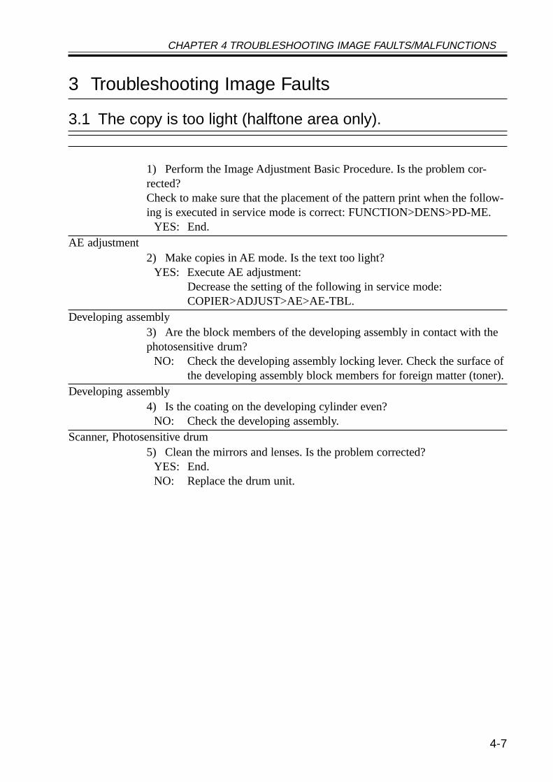
3.1 The copy is too light (halftone area only).
1) Perform the Image Adjustment Basic Procedure. Is the problem cor-rected?Check to make sure that the placement of the pattern print when the follow-ing is executed in service mode is correct: FUNCTION>DENS>PD-ME.
YES: End.AE adjustment
2) Make copies in AE mode. Is the text too light?YES: Execute AE adjustment:
Decrease the setting of the following in service mode:COPIER>ADJUST>AE>AE-TBL.
Developing assembly3) Are the block members of the developing assembly in contact with thephotosensitive drum?
NO: Check the developing assembly locking lever. Check the surface ofthe developing assembly block members for foreign matter (toner).
Developing assembly4) Is the coating on the developing cylinder even?
NO: Check the developing assembly.Scanner, Photosensitive drum
5) Clean the mirrors and lenses. Is the problem corrected?YES: End.NO: Replace the drum unit.
CHAPTER 4 TROUBLESHOOTING IMAGE FAULTS/MALFUNCTIONS
4-8
3.2 The copy is too light (including solid black).
1) Perform the Image Adjustment Basic Procedure. Is the problem cor-rected?Check to make sure that the placement of the pattern print when the follow-ing is executed in service mode is correct: FUNCTION>DENS>PD-ME.
YES: End.
2) Turn off the main power switch in the middle of copying operation, andopen the front cover. Is the toner image on the photopositive drum beforetransfer more or less normal?
NO: Go to step 7.Feeding unit (Transfer charging roller)
3) Is the feeding unit locked in place correctly?NO: Check the transfer charging roller pressure spring.
4) Is there electrical leakage around the electrode of the feeding unit?YES: Check the electrode of the feeding unit.
5) Is there dirt, cracking, or scratching on the transfer charging roller?YES: Replace the transfer charging roller.
6) Are the position and the condition of the transfer charging roller lockingspring normal?
NO: Correct the position of the spring, or replace the spring.Paper (transfer faulty)
7) Try paper fresh out of package. Is the problem corrected?YES:• The paper may be moist. Advise the user on the correct method of
storing paper.• Advise the user that the use of paper not of a recommended type
may fail to produce poor images.
CHAPTER 4 TROUBLESHOOTING IMAGE FAULTS/MALFUNCTIONS
4-9
Transfer guide, High-voltage cord, Composite power supply PCB, DC controller PCB(transfer faulty)8) Is there foreign matter in the transfer guide assembly or the transfercharging roller assembly, and is leakage noted?
YES: Remove the foreign matter.NO:1. Check the high-voltage cord for electrical continuity. (The resis-
tance of the transfer high-voltage cord is about 10 kΩ.)2. Check the composite power supply PCB and the DC controller
PCB.Developing assembly
9) Is the developing assembly fitted securely? (Check to see if the develop-ing block members are in firm contact with the photosensitive drum.)
NO: Fit the developing assembly correctly.Toner level detection assembly (development fault)
10) Is there toner inside the developing assembly?NO:• Check the toner sensor.• Check the connectors and the harnesses for electrical continuity.
Drum unit, Reader controller PCB, Main controller PCB11) Try replacing the drum unit. Is the problem corrected/
YES: End.NO: Real the reader controller PCB and the main controller PCB.
Memo
• The resistance of the high-voltage cord for primary charging is about 10kΩ
• The resistance of the high-voltage cord (white) is about 10 kΩ• The resistance of the cord for the transfer guide is about 10 kΩ
CHAPTER 4 TROUBLESHOOTING IMAGE FAULTS/MALFUNCTIONS
4-10
3.3 The copy is too light (entire face, considerable).
1) Perform the Image adjustment Basic Procedure. Is the problem cor-rected?Check to make user that the placement of the pattern print when executingthe folding is correct: FUNCTION>DENS>PD-ME.
YES: End.AE adjustment
2) Turn off the main power switch in the middle of copying operation, andopen the front cover. At this time, is the toner image on the surface of thephotosensitive drum before transfer more or less normal?
NO: Go to step 5.Developing assembly
3) Are the developing members in firm contract with the drum?NO: Check the developing assembly locking lever. Check the surface of
the developing members for foreign matter (toner).Developing clutch
4) Is the developing cylinder rotating?NO: Check the developing clutch (for a lose hex screw).
Feeding unit (tranfer charging roller)5) Is the feeding unit locked in place correctly?Is the transfer roller in contact with the photosensitive drum whet the feed-ing unit is locked in place?
NO:• Check the transfer charging roller pressure spring.• Check the feeding locking assembly.
6) Is there leakage in the electrode assembly of the feeding unit?YES: Check the electrode assembly of the feeding unit.
High-voltage cord, Feeding unit (Transfer charging roller)7) Is the feed electric continuity from the composite power supply PCB tothe electrode assembly of the feeding unit? (The resistance of the high-volt-age cord of the transfer charging roller is about 10 kΩ.)
NO:• Replace the high-voltage cord.• Check the feeding unit.
Composite power supply PCB, DC controller PCB8) Is there electrical continuity from the composite power supply PCB tothe feeding unit? (The resistance of the high-voltage cord of the transfercharging roller is about 10 kΩ.)
YES: Check the composite power supply PCB and the DC controllerPCB.
CHAPTER 4 TROUBLESHOOTING IMAGE FAULTS/MALFUNCTIONS
4-11
Transfer guide9) Is there foreign matter in the transfer guide assembly or the transfercharging roller assembly, and is there electrical leakage?
YES: Remove the foreign matter.Paper
10) Is there foreign matter in the transfer guide assembly or the transfercharging roller, and is there leakage?
NO: Try fresh paper or paper of a different type.Development (fault)
11) Is the developing assembly in firm contact with the photosensitivedrum? (Check to see that the developing block members are in firm contactwith the photosensitive drum.)
NO: Fit the developing assembly once again.YES:• Check the developing assembly.• Check the developing bias.
CHAPTER 4 TROUBLESHOOTING IMAGE FAULTS/MALFUNCTIONS
4-12
3.4 The copy has uneven density (darker at front).3.5 The copy has uneven density (lighter at front).
Developing assembly1) Are the developing block members of the developing assembly in firmcontact with the developing assembly?
NO: Check the developing assembly locking unit.Scanner
2) Clean the scanning lamp, reflecting plate, mirrors, and lenses. Is theproblem corrected?
YES: End.Pre-exposure lamp
3) Is the pre-exposure lamp ON during copying operation?NO:1. Replace the pre-exposure lamp unit.2. Replace the DC controller PCB.
Developing assembly4) Is the coating of toner on the developing cylinder even?
NO:1. Clean the tip of the blade of the developing assembly. (dry wiping)2. Clean the surface of the developing cylinder.3. Check the toner inside the developing assembly for uneven deposit.
5) Try the following modes. Is the problem corrected?• APVC adjustment once gain in service mode: FUNCTION>DPC>D-GAMMA.• ATVC adjustment once again in user mode: ‘roller clean’ under ‘adjust/clean’.
YES: End.Drum cartridge, Shading
6) Is there an uneven image in the halftone area of PG?YES: Replace the drum unit.NO: Execute shading adjustment (i.e., FUNCTION>CCD>CCD-ADJ).
CHAPTER 4 TROUBLESHOOTING IMAGE FAULTS/MALFUNCTIONS
4-13
3.6 The copy is foggy (entire face).
Scanner1) Clean the scanning lamp, reflecting plate, mirrors, and lenses. Is theproblem corrected?
YES: End.
2) Perform the Image Adjustment Basic Procedure. Is the problem cor-rected?
YES: End.
3) Select the following in service mode, and press the OK key:COPIER>FUNCTION>DPC>D-GAMAM. Is the problem corrected?
NO: Replace the drum unit. However, be sure to take appropriate mea-sures, as a fault in the following is suspected: main controller PCB,DC controller PCB, composite power supply PCB.
Developing assembly4) Is the developing cylinder insulated from the GND of the machine?(Turn off the main power switch, and disconnect the connector J130 of thecomposite power supply PCB; then, check the length between J130-1 andthe metal plate of the host machine for electrical continuity.)
NO: Check the area around the developing cylinder and the develop-ment connectors.
High-voltage system5) Is PG solid white foggy?
YES: Check the high-voltage system.Service mode
6) Adjust the setting of the following up to +30 of the factory value:ADJUST>DEVELOP>DE-OFST. Is the problem corrected?
YES: End.Developing bias, DC controller PCB
7) Try replacing the composite power supply. Is the problem corrected?YES: End.NO: Replace the DC controller PCB.
CHAPTER 4 TROUBLESHOOTING IMAGE FAULTS/MALFUNCTIONS
4-14
3.7 The copy is foggy (vertical).3.8 The copy has a black line (vertical, fuzzy, thick).
Primary charging roller1) Clean the charging roller in user mode. Is the problem corrected?
YES: End.Scanner
2) Clean the mirrors and lenses. Is the problem corrected?YES: End.
Developing assembly3) Is the coating of toner on the developing cylinder even?
NO:1. Check the edge of the blade of the developing assembly.2. Dry wipe the surface of the developing cylinder.
Photosensitive drum, External light4) Is there a scratch in the peripheral direction on the surface of the photo-sensitive drum?
YES: Replace the drum unit.NO: Check to see if the photosensitive drum is subjected to light from
outside.
CHAPTER 4 TROUBLESHOOTING IMAGE FAULTS/MALFUNCTIONS
4-15
3.9 The copy has a black line (vertical, fine).
Exposure system1) Generate a halftone test print in service mode. Enter ‘5’ toCOPIER>PG>TYPE. Does the output image have a black line?
NO: Suspect a fault in the exposure system. Clean it.Primary charging roller
2) Clean the primary charging roller. Is the problem corrected?YES: End.
Photosensitive drum3) Is there a scratch or a black line in the peripheral direction of the sur-face of the photosensitive drum?• Be sure to wipe the black line on the surface of the photosensitive drumwith a cloth coated with toner, and make sure that the black line disappears.
NO: Replace the drum unit.• If there is a scratch, be sure to identify the cause.
Fixing assembly4) Is there a scratch it the peripheral direction of the fixing roller?
YES: Replace the fixing roller.NO: Check the fixing inlet assembly for dirt.
CHAPTER 4 TROUBLESHOOTING IMAGE FAULTS/MALFUNCTIONS
4-16
3.10 The copy has a white spot (vertical).3.11 The copy has a white line (vertical).
Exposure system1) Generate a halftone test print in service mode. Enter ‘4’ to the follow-ing: COPIER>PG>TYPE. Does the output image have a white line/spot?
NO: Go to step 7.dirt (lint)
2) Is there dirt (lint) in the drum unit or around the laser optical path of thedeveloping assembly?
YES: Remove the dirt (lint).Transfer charging roller, Separation static eliminator
3) Is the transfer charging roller or the separation static eliminator soiledor coated with foreign matter?
YES: Clean the transfer charging roller or the separation static eliminator.If the problem is still not corrected, replace the transfer chargingroller or the separation static eliminator.
Developing assembly4) Is the coating of toner on the developing cylinder even?
NO: Check the edge of the developing assembly. If the developing as-sembly is without toner, see the descriptions under “The Add Tonermessage fails to go ON.”
Fixing film5) Is there a scratch in the peripheral direction of the fixing film?
YES: Replace the fixing film unitFixing assembly inlet
6) Is there dirt or foreign matter on the fixing assembly inlet?YES: Clean the inlet.
Photosensitive drum7) Is there a scratch in the peripheral direction of the photosensitive drum?
YES: Replace the drum unit.• Be sure to identify the cause of the scratch.
Exposure system, Standard white plate8) Clean the copyboard glass (stander white plate) and the mirrors. Is theproblem corrected?
YES: End.NO: Change the setting in the following service mode to change the
point of shading measurement: FUNCTION>SHDG-POS. If theproblem is not corrected after several attempts, replace thecopyboard glass.
CHAPTER 4 TROUBLESHOOTING IMAGE FAULTS/MALFUNCTIONS
4-17
3.12 The copy has a white spot (horizontal).
Exposure system1) Generate a halftone test print in service mode. Enter ‘4’ to the follow-ing: COPIER>PG>TYPE. Does the output image have a white spot?
NO: Go to step 4.Developing assembly
2) Does the problem occur at intervals of about 35 mm?YES:• Clean the developing block members.• Dry wipe the surface of the developing cylinder.• If a scratch is found on the surface of the developing cylinder, re-
place the developing cylinder.Drum unit
3) Does the problem occur at intervals of about 94 mm?YES:• Clean the drum.• If a scratch is found on the drum, replace the drum unit.
Paper4) Try paper fresh out of package.
YES: The paper may be moist. Advise the user on the correct method ofstoring paper.
Transfer charging roller, Developing bias5) Is there a white spot on the photosensitive drum during copying opera-tion?
NO: Check the transfer charging roller for leakage.YES: Check the developing bias.
CHAPTER 4 TROUBLESHOOTING IMAGE FAULTS/MALFUNCTIONS
4-18
3.13 The back of the copy is soiled/Soiled edge.
Exposure system1) Turn off the main power switch while paper is moving in the feedingassembly. At this time, is the back of the paper soiled?
NO: Go to step 5.Transfer guide assembly
2) Does the back of paper soiled after replacing the drum that caused ablack line or the like?
YES: Clean the transfer guide.Transfer guide bias, Transfer guide
3) During copying, is the voltage between the transfer guide (+) and themachine side plate (-) about -50 to -650V?
NO:• Check the transfer guide bias connector.• Clean the transfer guide.• Clean the bottom of the developing assembly.
Developing assembly, Registration roller, Drum cleaner4) Does the problem occur at intervals of about 50 mm?
YES:• Clean the registration roller.• Clean the transfer guide.• Check the developing assembly for leakage of toner.• Clean the bottom of the developing assembly.NO:• Clean the feeding assembly.• Clean the transfer guide.• Check the drum cleaner assembly fro leakage of waste toner.
Transfer charging roller5) Execute cleaning of the roller in user mode. Is the problem corrected?
YES: End.Fixing assembly
6) Run COPIER>OPTION>BODY>FIX-CLN. Fixed?No: If the fixing roller cleaner is soiled, replace itYES: End.
CHAPTER 4 TROUBLESHOOTING IMAGE FAULTS/MALFUNCTIONS
4-19
3.14 The copy has a fixing fault.
1) Does the problem occur when the machine is first turned on (as in themorning)?
NO: Go to step 3.
2) Is the paper thick or the like, which has poor fixing quality?YES: Select ‘thick paper’, and try feeding paper from the multifeeder.
Fixing film3) Is the problem vertical?
YES: If a scratch is found on the fixing film, replace the film unit.Fixing heater
4) Does the heater operate?NO: See “The fixing heater fails to operate.”
Fixing lower roller pressure5) Is the lower roller pressure (nip width) as indicated?
NO: Replace the fixing assembly.Thermistor
6) Does the indication in the following service mode increase:COPIER>DISPLAY>ANALOG>FIX-C?
NO: Replace the film unit.Paper
7) Is the paper of a recommended type?NO: Try paper of a recommended type. If the result is good, advise the
user to use paper of a recommended type.Service mode
8) Set priority on fixing in the following service mode:COPIER>OPTION>BODY>FIX-TEMP. Is the problem corrected?
YES: End.
CHAPTER 4 TROUBLESHOOTING IMAGE FAULTS/MALFUNCTIONS
4-20
3.15 The copy has a displaced leading edge.3.16 The copy has a displaced leading edge (large margin).3.17 The copy has a displaced margin (no margin).
1) Is an ADF used?YES: Correct the displacement by referring to the Service Manual of the
ADF.Original
2) Is the original placed correctly?NO: Place the original correctly.
Pickup roller, Feeding roller, Separation roller3) Has the pickup, feeding, or separation roller of the cassette in questionreached the end of its life?
YES: Check the roller; if worn, replace it.REGIST
4) Execute the following in service mode: ADJUST>FEED-ADJ>REGIST. Is the problem corrected? (Note 1)
YES: End.Registration roller, Pickup/Feeding guide
5) Does the problem occur only in double-sided mode?YES: Check the rollers of the duplex feeding assembly.NO: Check and clean the following:• Registration rollers• Pickup/feeding guide
Note 1:Making Adjustments
• Generate a PG test pattern ( [6] ; solid bal).• Make adjustments so that the leading edge margin is 2.5 ± 1.5 mm. A higher setting
will decrease the margin.
CHAPTER 4 TROUBLESHOOTING IMAGE FAULTS/MALFUNCTIONS
4-21
3.18 The copy is blurred.
Scanner drive cable1) Is the cable wound on the wire pulley twisted or twined when the scan-ner is moving? Is there e foreign matter in the mirror pulley assembly?
YES:• Route the cable correctly.• Replace the cable.• Remove the foreign matter.
Scanner rail2) Move the No. 1 mirror base slowly by hand. Does it move smoothly?
NO: Clean the surface of the scanner rail with alcohol; thereafter, applya small amount of silicone oil.
Drum drive assembly, Photosensitive drum3) Does the problem occur at intervals of about 94 mm?
YES:• Check the drum drive assembly.• Check the drum ends (where developing block members remain in
contact) for a scratch or foreign matter.Developing gear, Drum drive assembly, Drum unit
4) Does the problem occur at intervals of about 35 mm?YES: Check the developing assembly.NO:• Check the drum drive assembly.• Replace the drum unit.
CHAPTER 4 TROUBLESHOOTING IMAGE FAULTS/MALFUNCTIONS
4-22
3.19 The copy is foggy (horizontal).
1) Does the problem occur at the same position on all copies made in Di-rect.
YES: Go to step 5.Scanning lamp
2) Does the scanning lamp flicker while the scanner is moving forward?YES: Check the scanning lamp and the inverter PCB.
Drum unit3) Does the problem occur at intervals of 94 mm?
YES: Replace the drum unit.Wiring
4) Is the wiring between the scanning lamp, the inverter PCB and thereader assembly?
NO: Correct the wiring.Developing assembly
5) Is the coating of toner on the developing cylinder normal?NO: Check the developing bias.
Scanner, Feeding system6) Make reduced copies (about 50% to 60%), and compare them againstcopies made in Direct. Is the position of the problem different?
YES: Check the scanner.NO: Check the feeding assembly.
CHAPTER 4 TROUBLESHOOTING IMAGE FAULTS/MALFUNCTIONS
4-23
3.20 The copy has inadequate sharpness.
Copyboard glass1) Is there oil or the like on the copyboard glass? Is there foreign matter onthe copyboard glass stay?
YES: Clean the copyboard glass.Scanner
2) Clean the scanning lamp, reflecting plate, mirrors, and lenses. Is theproblem corrected?
YES: End.Mirror (position)
3) Is the horizontal reproduction ratio in Direct as indicated?NO: Adjust the position of the No. 1 mirror an the No. 2 mirror.
Developing bias4) Are the connection and the electrical continuity of the high-voltage forthe developing bias normal? (The resistance of the cable for the developingbias and the resistance between the terminal of the composite power supplyPCB and the terminal on the developing assembly is about 10 kΩ.)
NO: Check the connection; and replace the cable. If the problem is stillnot corrected,
1. Replace the composite power supply PCB2. Replace the DC controller PCB.
Drum unit, Transfer charging system5) Try replacing the drum unit. Is the problem corrected?
YES: End.NO: Check the transfer charging system.

CHAPTER 4 TROUBLESHOOTING IMAGE FAULTS/MALFUNCTIONS
4-24
3.21 The copy is completely blank.
Developing assembly1) Is the developing assembly locked to the photosensitive drum duringcopying?
NO: Check the locking mechanism of the developing assembly.Developing assembly drive mechanism
2) Is the developing cylinder rotating during copying?NO: Check the drive mechanism of the developing assembly.
3) Is the image of the test print (PG>TYPE; 1 through 8) normal?YES: Go to step 10.
Transfer charging roller4) Is the transfer charging roller mounted properly?
NO: Check the mounting condition.5) Is leakage noted on the transfer charging roller?
YES: Check the transfer charging roller.Transfer high-voltage cord
6) Is the connection of the transfer high-voltage cord normal? Is there elec-trical continuity in the transfer high-voltage cord? (The resistance of thetransfer high-voltage cord is about 10 kΩ.)
NO:• Connect the cord properly.• Replace the transfer high-voltage cord.
DC controller PCB7) Try replacing the DC controller PCB. Is the problem corrected?
YES: End.Composite power supply PCB
8) Try replacing the composite power supply PCB. Is the problem cor-rected?
YES: End.Power supply (to CCD PCB)
9) Is about 12 VDC present on J602-1 of the CCD PCB? Is about 5 VDCpresent on J602-4?
NO: Check the wiring; if normal, replace the reader controller PCB.

CHAPTER 4 TROUBLESHOOTING IMAGE FAULTS/MALFUNCTIONS
4-25
Wiring10) Is the wiring between the CCD PCB and the reader controller PCB nor-mal?
NO: Correct the wiring.Laser scanner unit, Drum unit
11) Try replacing the drum unit. Is the problem corrected?NO: Check the laser shutter mechanism; if normal, replace the laser
scanner unit.YES: End.
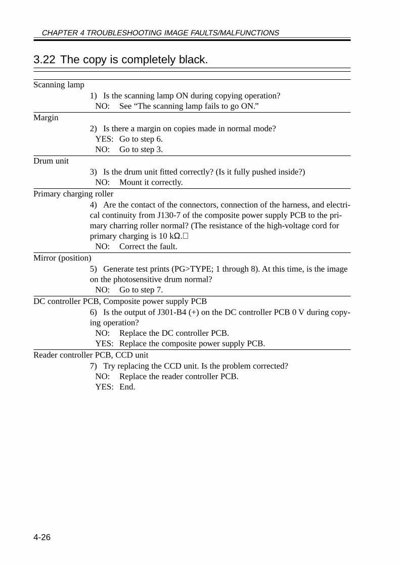
CHAPTER 4 TROUBLESHOOTING IMAGE FAULTS/MALFUNCTIONS
4-26
3.22 The copy is completely black.
Scanning lamp1) Is the scanning lamp ON during copying operation?
NO: See “The scanning lamp fails to go ON.”Margin
2) Is there a margin on copies made in normal mode?YES: Go to step 6.NO: Go to step 3.
Drum unit3) Is the drum unit fitted correctly? (Is it fully pushed inside?)
NO: Mount it correctly.Primary charging roller
4) Are the contact of the connectors, connection of the harness, and electri-cal continuity from J130-7 of the composite power supply PCB to the pri-mary charring roller normal? (The resistance of the high-voltage cord forprimary charging is 10 kΩ.)
NO: Correct the fault.Mirror (position)
5) Generate test prints (PG>TYPE; 1 through 8). At this time, is the imageon the photosensitive drum normal?
NO: Go to step 7.DC controller PCB, Composite power supply PCB
6) Is the output of J301-B4 (+) on the DC controller PCB 0 V during copy-ing operation?
NO: Replace the DC controller PCB.YES: Replace the composite power supply PCB.
Reader controller PCB, CCD unit7) Try replacing the CCD unit. Is the problem corrected?
NO: Replace the reader controller PCB.YES: End.
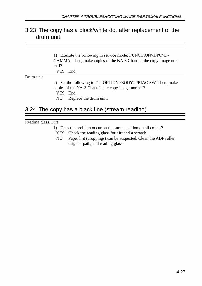
CHAPTER 4 TROUBLESHOOTING IMAGE FAULTS/MALFUNCTIONS
4-27
3.23 The copy has a block/white dot after replacement of thedrum unit.
1) Execute the following in service mode: FUNCTION>DPC>D-GAMMA. Then, make copies of the NA-3 Chart. Is the copy image nor-mal?
YES: End.Drum unit
2) Set the following to ‘1’: OPTION>BODY>PRIAC-SW. Then, makecopies of the NA-3 Chart. Is the copy image normal?
YES: End.NO: Replace the drum unit.
3.24 The copy has a black line (stream reading).
Reading glass, Dirt1) Does the problem occur on the same position on all copies?
YES: Check the reading glass for dirt and a scratch.NO: Paper lint (droppings) can be suspected. Clean the ADF roller,
original path, and reading glass.
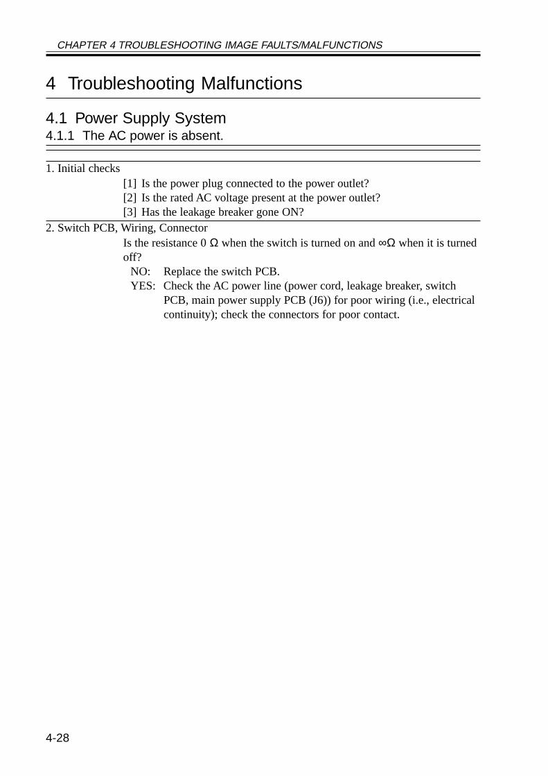
CHAPTER 4 TROUBLESHOOTING IMAGE FAULTS/MALFUNCTIONS
4-28
4 Troubleshooting Malfunctions
4.1 Power Supply System4.1.1 The AC power is absent.
1. Initial checks[1] Is the power plug connected to the power outlet?[2] Is the rated AC voltage present at the power outlet?[3] Has the leakage breaker gone ON?
2. Switch PCB, Wiring, ConnectorIs the resistance 0 Ω when the switch is turned on and ∞Ω when it is turnedoff?
NO: Replace the switch PCB.YES: Check the AC power line (power cord, leakage breaker, switch
PCB, main power supply PCB (J6)) for poor wiring (i.e., electricalcontinuity); check the connectors for poor contact.
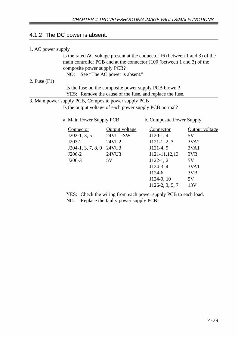
CHAPTER 4 TROUBLESHOOTING IMAGE FAULTS/MALFUNCTIONS
4-29
4.1.2 The DC power is absent.
1. AC power supplyIs the rated AC voltage present at the connector J6 (between 1 and 3) of themain controller PCB and at the connector J100 (between 1 and 3) of thecomposite power supply PCB?
NO: See “The AC power is absent.”2. Fuse (F1)
Is the fuse on the composite power supply PCB blown ?YES: Remove the cause of the fuse, and replace the fuse.
3. Main power supply PCB, Composite power supply PCBIs the output voltage of each power supply PCB normal?
a. Main Power Supply PCB b. Composite Power Supply
YES: Check the wiring from each power supply PCB to each load.NO: Replace the faulty power supply PCB.
ConnectorJ202-1, 3, 5J203-2J204-1, 3, 7, 8, 9J206-2J206-3
Output voltage24VU1-SW24VU224VU324VU35V
ConnectorJ120-1, 4J121-1, 2, 3J121-4, 5J121-11,12,13J122-1, 2J124-3, 4J124-6J124-9, 10J126-2, 3, 5, 7
Output voltage5V3VA23VA13VB5V3VA13VB5V13V
CHAPTER 4 TROUBLESHOOTING IMAGE FAULTS/MALFUNCTIONS
4-30
4.2 Printer Unit4.2.1 Pickup fails.
1. General conditionSlide out and then in the cassette. Is the sound of the lifter fall heard?
NO: See “The lifter fails to move up.”2. Sensor
In service mode (COPIER>DISPLAY>JAM) find the sensor that detectedthe jam. Is the sensor lever and the sensor itself normal?
NO: Replace the sensor lever or the sensor.3. Releasing lever (for pickup/separation roller)
Push in the releasing lever toward the rear. Is the pickup roller released? Dothe feeding roller and the separation roller come into firm contact?
NO: The releasing lever (spring) is displaced or deformed. Correct orreplace it.
4. Pickup/feeding/separation rollerExecute pickup operation. Does the roller rotate?
YES: The movement of paper is faulty because of wear on the pickup/feeding/separate roller. Replace the roller.
5. Pickup drive assemblyIs there damage/foreign matter on the gear of the pickup roller drive assem-bly?
YES: Replace the gear. Remove the foreign matter.6. Pickup motor (M2)
Execute the following in service mode: code 3 ofCOPIER>FUNCTION>PART-CHK>MTR; i.e., MTR-ON. Is the motorcontrol signal present at J1602 of the pickup PCB? (J1602-1: A*, J1602-2:A, J1602-3: B*, J1602-4: B)
YES: Replace the pickup motor.7. Pickup PCB, DC controller PCB
Execute the following in service mode: code 3 ofCOPIER>FUNCTION>PART-CHK>MTR; i.e., MTR-ON. Is the motorcontrol signal present at J302A of the DC controller PCB? (J302A-1: 24 V,J302A-3: GND, J302A-6: IN1, J302A-7: IN2, J302A-8: IN3, J302A-8:IN4)
YES: Replace the pickup PCB.NO: Replace the DC controller PCB.
CHAPTER 4 TROUBLESHOOTING IMAGE FAULTS/MALFUNCTIONS
4-31
4.2.2 The lifter fails to move up (pickup from the cassette).
1. Releasing lever (for pickup roller)Push in the releasing lever toward the rear. Does the descent movement ofthe pickup roller stop?
NO: The releasing lever (spring) is displaced or deformed. Correct orreplace it.
2. Lifter gear retaining lever lockWhen the cassette is slid in, is the lock of the lifter gear retaining level re-leased?
NO: Correct the locking mechanism of the lifter gear retaining lever orreplace it.
3. Lifter gear, Lifter gear retaining lever, Lifter ascent leverIs any of the gear faulty (damaged)?
YES: Replace it.4. Lifter drive assembly
Is the gear of the lifter drive assembly damaged or subject to foreign matter.Is the drive belt faulty?
YES: Replace the gear/belt. Remove the foreign matter.5. Pickup roller descent solenoid (SL1C)
Execute the following in service mode: code 6 ofCOPIER>FUNCTION>PART-CHK>SL; i.e., SL-ON. Is the solenoid drivevoltage present at J1604 of the pickup PCB? (J1604-4: 24 V, J1604-1:PICKUPSL*)
YES: The pickup roller solenoid is faulty. Replace it.6. Pickup PCB, DC controller PCB
Execute the following in service mode: code 6 ofCOPIER>FUNCTION>PART>CHK>SL; i.e., SL-ON. Is the solenoid con-trol signal present at J302A-5 of the DC controller PCB? (J302A-5:FDOWN_SL*)
YES: Replace the pickup PCB.NO: Replace the DC controller PCB.
CHAPTER 4 TROUBLESHOOTING IMAGE FAULTS/MALFUNCTIONS
4-32
4.2.3 The vertical path roller fails to rotate.
1. Main motorIs ‘E010’ (faulty main motor) indicated?
YES: See the descriptions on E010 in Chapter 6 “Self Diagnosis.”2. Vertical path clutch (CL1)
Execute the following in service mode: code 1 ofCOPIER>FUNCTION>PART-CHK>CL, i.e., CL-ON. Is the clutch drivesignal present at J1603 of the pickup PCB? (J1603-4: 24 V, J1603-1:VPATHCL*)
YES: The vertical path clutch is faulty. Replace the clutch.3. Pickup PCB, DC controller PCB
Execute the following in service mode: code 1 ofCOPIER>FUNCTION>PART-CHK>CL; i.e., CL-ON. Is the clutch controlsignal present at J302A-4 of the DC controller PCB?
YES: Replace the pickup PCB.NO: Replace the DC controller PCB.
4.2.4 The registration roller fails to rotate.
1. Registration paper sensor (PS10)When paper is placed over the sensor, does bit 3 change from ‘0’ to ‘1’?(service mode: COPIER>I/O>DC-CON>IO-P015)?NO: The registration paper sensor is faulty. Replace the sensor.
2. Registration MOTOR (M9)Execute the following in service mode: code 9 ofCOPIER>FUNCTION>PART-CHK>MTR. Is the motor drive signalpresent at J309 of the DC controller PCB? (J309-1: REG_A, J309-2:REG_A*, J309-3: 24 VU, J309-4: 24 VU, J309-5: REG_B, J309-6:REG_B*)
YES: The registration motor is faulty. Replace the motor.NO: The DC controller PCB is faulty. Replace the PCB.
CHAPTER 4 TROUBLESHOOTING IMAGE FAULTS/MALFUNCTIONS
4-33
4.2.5 Pickup from the multifeeder tray fails (i.e., the pickup roller fails to ro-tate).
1. Main motorIs ‘E010’ (faulty main motor) indicated?
YES: See the description on ‘E010’ in Chapter 6 “Self Diagnosis.”2. Multifeeder paper sensor (PS22)
Place paper in the multifeeder. Does bit 5 change from ‘0 to ‘1’? (servicemove COPIER>I/O>DC-CON>IO-PO16)
NO: Check the wiring and the link; if normal, replace the sensor.3. Multifeeder clutch (CL2), DC controller PCB
Execute the following in service mode: code 2 ofCOPIER>FUNCTION>PATH-CHK>CL; i.e., CL-ON. Is the clutch drivesignal present between J302B-7 and -8 of the DC controller PCB? (J302B-7: 24 V, J302B-8: MLT_CL)
YES: Check the wiring; if normal, replace the clutch.NO: Replace the DC controller PCB.
4.2.6 Pickup from the multifeeder tray fails (i.e., the multifeeder holdingplate fails to move up).
1. Main motorIs ‘E010’ (faulty main motor) indicated?
YES: See the description on ‘E010’ in Chapter 6 “Self Diagnosis.”2. Multifeeder holding plate releasing solenoid (SL5)
Execute the following in service mode: code 4 ofCOPIER>FUNCTION>PART-CHK>SL; i.e., SL-ON. Is the solenoid drivesignal present between J308A-1 and -2 on the DC controller PCB? (J308A-2: 24 V, J308A-1: MLT_SL)
YES: Check the wiring and the link; if normal, replace the solenoid.NO: Replace the DC controller PCB.
CHAPTER 4 TROUBLESHOOTING IMAGE FAULTS/MALFUNCTIONS
4-34
4.2.7 The photosensitive drum fails to rotate.
1. Main motorIs ‘E010’ (faulty main motor) indicated?
YES: See the description on ‘E010’ in Chapter 6 “Self Diagnosis.”2. Drum unit, Drum drive unit
Remove and then mount bak the drum unit. Is the problem corrected?YES: Yes.NO: Check the drum unit and the drive assembly of the drum drive unit.
If a fault is discovered, correct the fault or replace the unit.
4.2.8 The pre-exposure lamp fails to go ON.
1. Pre-exposure lamp (LAMP2), DC controller PCBExecute the following in service mode: COPIER>FUNCTION>MISC-P>PRE-EXP. Is the activation control signal present at J312B of the DCcontroller PCB? (J312B-6: 24 V, J312B-7: PREEXPOSE)
YES: Check the wiring from the DC controller PCB to the pre-exposurelamp; if normal, replace the pre-exposure lamp.
NO: Replace the DC controller PCB.
CHAPTER 4 TROUBLESHOOTING IMAGE FAULTS/MALFUNCTIONS
4-35
4.3 Reader Unit4.3.1 The No. 1 mirror base fails to move.
1. Initial checkIs the scanner motor driven?
YES: Go to step 2.NO: Go to step 4.
2. Cable (displacement, broken), Drive belt (displaced, broken)Is the scanner drive cable or the drive belt normal?
NO: Replace or correct the cable of the drive belt.3. Scanner path (foreign matter)
Move the scanner by hand. Does it move smoothly?NO: Remove the dirt/foreign matter from the scanner rail. Remove any
object that comes into contact with the scanner. Use alcohol forcleaning; thereafter, apply a small amount of silicone oil (FY9-6010).If the inverter PCB is not positioned correctly, it can come intocontact with the scanner.
4. Wiring, ConnectorIs the connection of the wiring and connectors from J401 of the reader con-troller PCB to the scanner motor correct?
NO: Correct the wiring, and connect the connectors securely.5. Scanner motor (M400), Reader controller PCB
Is the drive signal present at J401 of the reader controller PCB? (J401-5/6:+24 V, J401-1/2/3/4: drive pulse)
YES: Replace the scanner motor.NO: Replace the reader controller PCB.
CHAPTER 4 TROUBLESHOOTING IMAGE FAULTS/MALFUNCTIONS
4-36
4.3.2 The scanning lamp fails to go ON.
1. Wiring, ConnectorIs the connection of the wiring and the connectors between the inverter PCB(J4061) and the lamp correct?
NO: Correct the wring, and connect the connectors securely.2. Inverter PCB
Is ‘E220’ indicated?YES: Replace the inverter PCB.
3. Scanning lamp, Reader controller PCBExecute the following in service mode: COPIER>FUNCTION>MISC-R>SCANLAMP. Is the activation control signal present at J402 of thereader controller PCB? (J402-2: LMP_ON, J402-3: GND, J402-4: +24 VU)
YES: The scanning lamp is faulty. Replace the lamp.NO: The reader controller PCB is faulty. Replace the PCB.
CHAPTER 4 TROUBLESHOOTING IMAGE FAULTS/MALFUNCTIONS
4-37
4.4 Message Indication4.4.1 The “Add Toner” message fails to go OFF.
1. Toner sensor (S1), DC controller PCBAfter toner supply, is ‘0’ (absence of toner) indicated in the following ser-vice mode: bit 0 of COPIER>I/O>DC-CON>P008?
YES: The toner sensor is faulty. Replace the sensor.NO: Check the wiring; if normal, replace the DC controller PCB.
4.4.2 The “Control Card Set” message fails to go OFF (when no cardreader is installed).
1. Shorting connectorWhen the main controller is replaced, the shorting connector must be re-moved from the old PCB and mounted to the new PCB. Is the shorting con-nector fitted to the connector J1060 of the main control card?
NO: Fit the shorting connector.YES: The main controller PCB is faulty. Replace the PCB.
4.4.3 The “Add Paper” message fails to go OFF.
1. Cassette pickup assemblyIs the lifter mechanism of the cassette normal?
NO: See “The lifter fails to move up (pickup from cassette).”2. Cassette 1/2 paper sensor detecting lever
Are the shape, mounting, and operation of the paper sensor lever normal?NO: Correct or replace the sensor.
3. Pickup PCB, DC controller PCBWhen paper is placed in the cassette, is the paper detection signal present atJ302A of the DC controller PCB? (cassette 1: J302-A10 (from 0 to 5 V),cassette 2: J302-A11 (from 0 to 5 V))
NO: The paper sensor or the pickup PCB is faulty. Replace the PCB.YES: The DC controller PCB is faulty. Replace the PCB.
CHAPTER 4 TROUBLESHOOTING IMAGE FAULTS/MALFUNCTIONS
4-38
4.4.4 The “Close the Front Cover” message fails to go OFF.
1. ConnectorsIs the wiring between the PCBs secure?[1] between composite power supply PCB (J136A) and DC controller PCB(J301A)(24V detection signal: between J136A-3 and J301A-10)[2] between composite power supply PCB (J135) and main power supplyPCB (J202)(J135-1: 24VU1-SW, J135-2: 0VU1, J202-5: 24VU1-SW, J202-6: 0VU1)
NO: Make the wiring secure.2. Front cover switch
Is there electrical continuity in the front cover switch when the front coveris closed?(check the interval between J200-1 and J200-3 on the main power supplyPCB for electrical continuity.)
NO: Replace the front cover switch.3. Main power supply PCB
Is 24 V supplied by the main power supply PCB to the composite powersupply PCB?• Main power supply PCB (J202-5: 24VU1-SW, J202-6: 0VU1)• Composite power supply PCB (J135-1: 24VU1-SW, J135-2: 0VU1)
NO: Replace the main power supply PCB.4. Composite power supply PCB, DC controller PCB
When 24 V is supplied by the main power supply PCB to the compositepower supply, is the front cover detection signal (FDOOR_OPN) sent by thecomposite power supply PCB to the DC controller PCB?• Composite power supply PCB (J136A-3)• DC controller PCB (J301A-10)
YES: Replace the DC controller PCB.NO: Replace the composite power supply PCB.
CHAPTER 4 TROUBLESHOOTING IMAGE FAULTS/MALFUNCTIONS
4-39
4.5 Paper Deck4.5.1 Pickup fails.
1. Right upper cover, Right lower coverAre the right upper cover and the right lower cover closed securely?
NO: Close the covers.2. Lifter
When the compartment is slid out from the deck, does the lifter movedown? Further, when the compartment is slid into the deck, does the liftermove up?
NO: See “The deck lifter fails to move up.”3. Deck pickup roller
Does the deck pickup roller rotate?YES: If the roller is soiled, clean it with alcohol. If it is deformed be-
cause of wear, replace it.4. Belt (displacement)
Is the belt used to transmit drive to the deck pickup roller fitted correctly?NO: Fit the belt correctly.
5. GearIs the drive from the deck main motor transmitted to the pickup assembly?
NO: Check the drive assembly.6. Deck pickup clutch (CL2), Deck drive PCB
Measure the voltage of the connector (J5B) on the deck driver PCB. Whenthe Start key is pressed, is the clutch drive signal generated? (J5-B3:FEED_CL_ON*, J5-B4: 24 V)
YES: Check the wiring; if normal, replace the clutch.NO: Replace the deck driver PCB.
CHAPTER 4 TROUBLESHOOTING IMAGE FAULTS/MALFUNCTIONS
4-40
4.5.2 The deck lifter fails to move up.
1. Deck bodyIs the deck body mounted correctly?
NO: Mount the deck body correctly.2. Lifter cable
Is the lifter cable fitted correctly?NO: Fit the cable correctly.
3. Spring, LeverPush up the deck pickup roller releasing lever with your finger. Does thepickup roller move down?
NO: Remove the pickup assembly, and check the spring and the lever.4. Deck lifter motor (M2D)
Does the deck lifter motor rotate?YES: Go to step 6.
5. Deck open detecting switch (SW1D), Deck drive PCBDoes the voltage between J7-1 (+ : 24V OUT) and J7-3 (GND : 24V IN) ofthe deck driver PCB change from about 0 to 24 V?
YES: Check the wiring to the switch; if normal, replace the switch.NO: Replace the deck driver PCB.
6. Deck lifter lower limit detecting switch (SW2D), deck driver PCBDoes the voltage between J4-7 (+ : LIFT_LOW_LMT) and J4-8 (GND) ofthe deck driver PCB change from about 0 to 5 V?
YES: Check the lever and the wiring; if normal, replaced the switch.NO: Replace the deck driver PCB.
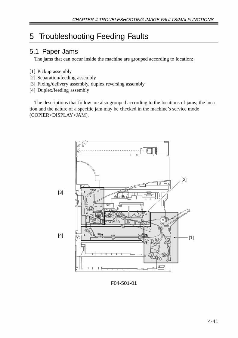
CHAPTER 4 TROUBLESHOOTING IMAGE FAULTS/MALFUNCTIONS
4-41
5 Troubleshooting Feeding Faults
5.1 Paper JamsThe jams that can occur inside the machine are grouped according to location:
[1] Pickup assembly[2] Separation/feeding assembly[3] Fixing/delivery assembly, duplex reversing assembly[4] Duplex/feeding assembly
The descriptions that follow are also grouped according to the locations of jams; the loca-tion and the nature of a specific jam may be checked in the machine’s service mode(COPIER>DISPLAY>JAM).
F04-501-01
[1][4]
[3]
[2]
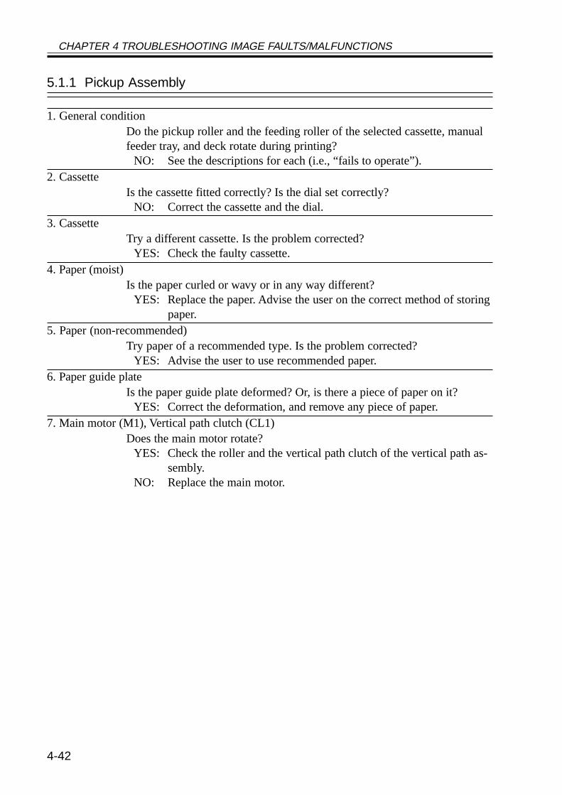
CHAPTER 4 TROUBLESHOOTING IMAGE FAULTS/MALFUNCTIONS
4-42
5.1.1 Pickup Assembly
1. General conditionDo the pickup roller and the feeding roller of the selected cassette, manualfeeder tray, and deck rotate during printing?
NO: See the descriptions for each (i.e., “fails to operate”).2. Cassette
Is the cassette fitted correctly? Is the dial set correctly?NO: Correct the cassette and the dial.
3. CassetteTry a different cassette. Is the problem corrected?
YES: Check the faulty cassette.4. Paper (moist)
Is the paper curled or wavy or in any way different?YES: Replace the paper. Advise the user on the correct method of storing
paper.5. Paper (non-recommended)
Try paper of a recommended type. Is the problem corrected?YES: Advise the user to use recommended paper.
6. Paper guide plateIs the paper guide plate deformed? Or, is there a piece of paper on it?
YES: Correct the deformation, and remove any piece of paper.7. Main motor (M1), Vertical path clutch (CL1)
Does the main motor rotate?YES: Check the roller and the vertical path clutch of the vertical path as-
sembly.NO: Replace the main motor.
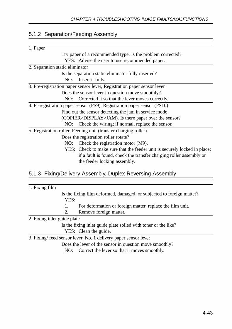
CHAPTER 4 TROUBLESHOOTING IMAGE FAULTS/MALFUNCTIONS
4-43
5.1.2 Separation/Feeding Assembly
1. PaperTry paper of a recommended type. Is the problem corrected?
YES: Advise the user to use recommended paper.2. Separation static eliminator
Is the separation static eliminator fully inserted?NO: Insert it fully.
3. Pre-registration paper sensor lever, Registration paper sensor leverDoes the sensor lever in question move smoothly?
NO: Corrected it so that the lever moves correctly.4. Pr-registration paper sensor (PS9), Registration paper sensor (PS10)
Find out the sensor detecting the jam in service mode(COPIER>DISPLAY>JAM). Is there paper over the sensor?
NO: Check the wiring; if normal, replace the sensor.5. Registration roller, Feeding unit (transfer charging roller)
Does the registration roller rotate?NO: Check the registration motor (M9).YES: Check to make sure that the feeder unit is securely locked in place;
if a fault is found, check the transfer charging roller assembly orthe feeder locking assembly.
5.1.3 Fixing/Delivery Assembly, Duplex Reversing Assembly
1. Fixing filmIs the fixing film deformed, damaged, or subjected to foreign matter?
YES:1. For deformation or foreign matter, replace the film unit.2. Remove foreign matter.
2. Fixing inlet guide plateIs the fixing inlet guide plate soiled with toner or the like?
YES: Clean the guide.3. Fixing/ feed sensor lever, No. 1 delivery paper sensor lever
Does the lever of the sensor in question move smoothly?NO: Correct the lever so that it moves smoothly.
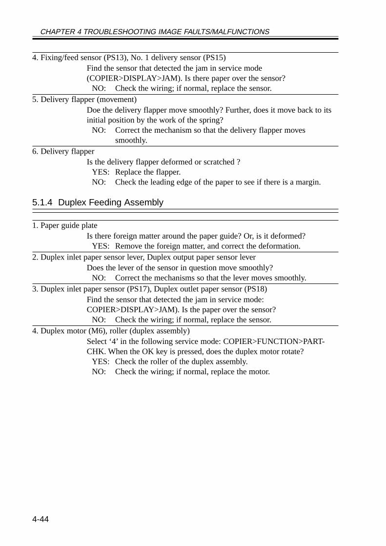
CHAPTER 4 TROUBLESHOOTING IMAGE FAULTS/MALFUNCTIONS
4-44
4. Fixing/feed sensor (PS13), No. 1 delivery sensor (PS15)Find the sensor that detected the jam in service mode(COPIER>DISPLAY>JAM). Is there paper over the sensor?
NO: Check the wiring; if normal, replace the sensor.5. Delivery flapper (movement)
Doe the delivery flapper move smoothly? Further, does it move back to itsinitial position by the work of the spring?
NO: Correct the mechanism so that the delivery flapper movessmoothly.
6. Delivery flapperIs the delivery flapper deformed or scratched ?
YES: Replace the flapper.NO: Check the leading edge of the paper to see if there is a margin.
5.1.4 Duplex Feeding Assembly
1. Paper guide plateIs there foreign matter around the paper guide? Or, is it deformed?
YES: Remove the foreign matter, and correct the deformation.2. Duplex inlet paper sensor lever, Duplex output paper sensor lever
Does the lever of the sensor in question move smoothly?NO: Correct the mechanisms so that the lever moves smoothly.
3. Duplex inlet paper sensor (PS17), Duplex outlet paper sensor (PS18)Find the sensor that detected the jam in service mode:COPIER>DISPLAY>JAM). Is the paper over the sensor?
NO: Check the wiring; if normal, replace the sensor.4. Duplex motor (M6), roller (duplex assembly)
Select ‘4’ in the following service mode: COPIER>FUNCTION>PART-CHK. When the OK key is pressed, does the duplex motor rotate?
YES: Check the roller of the duplex assembly.NO: Check the wiring; if normal, replace the motor.
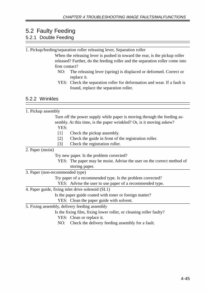
CHAPTER 4 TROUBLESHOOTING IMAGE FAULTS/MALFUNCTIONS
4-45
5.2 Faulty Feeding5.2.1 Double Feeding
1. Pickup/feeding/separation roller releasing lever, Separation rollerWhen the releasing lever is pushed in toward the rear, is the pickup rollerreleased? Further, do the feeding roller and the separation roller come intofirm contact?
NO: The releasing lever (spring) is displaced or deformed. Correct orreplace it.
YES: Check the separation roller for deformation and wear. If a fault isfound, replace the separation roller.
5.2.2 Wrinkles
1. Pickup assemblyTurn off the power supply while paper is moving through the feeding as-sembly. At this time, is the paper wrinkled? Or, is it moving askew?
YES:[1] Check the pickup assembly.[2] Check the guide in front of the registration roller.[3] Check the registration roller.
2. Paper (moist)Try new paper. Is the problem corrected?
YES: The paper may be moist. Advise the user on the correct method ofstoring paper.
3. Paper (non-recommended type)Try paper of a recommended type. Is the problem corrected?
YES: Advise the user to use paper of a recommended type.4. Paper guide, fixing inlet drive solenoid (SL1)
Is the paper guide coated with toner or foreign matter?YES: Clean the paper guide with solvent.
5. Fixing assembly, delivery feeding assemblyIs the fixing film, fixing lower roller, or cleaning roller faulty?
YES: Clean or replace it.NO: Check the delivery feeding assembly for a fault.
CHAPTER 4 TROUBLESHOOTING IMAGE FAULTS/MALFUNCTIONS
4-46
6 Outline of Electrical Components
6.1 IntroductionThe electrical components of the machine and its accessories are arranged as shown
herein, and they possess the functions discussed; the notations and the I/O addresses usedare based on those in the general circuit diagrams, enabling reference to the general circuitdiagrams for wiring and signal descriptions. (For the general circuit diagrams, see the Ap-pendix.)6.1.1 Guide to the List
The following notations are used to indicate the targets of connections:DC-CON: DC controller PCBR-CON: reader controller PCBMN-CON: main controller PCBFEED: pickup circuit PCBMPWS: main power supply PCBDECK-CON: side deck driver PCBDECK-FEED: 2-Cassette Pedestal Pickup PCBFAX-CON: G3 FAX control PCB
CHAPTER 4 TROUBLESHOOTING IMAGE FAULTS/MALFUNCTIONS
4-47
6.1.2 Checking the PhotointerruptersThe photointerrupters are checked in service mode; go through the tables attached to the
lists of electrical components to find out the state* of a specific sensor, which may be any ofthe following:a. Paper Sensor
Move the sensor lever by hand to simulate the presence of paper; then, check the ServiceMode screen.
If it is difficult to check the Service Mode screen while moving the sensor lever, put paperover the point of detection, and then check the Service Mode screen.
b. Open/Closed SensorCheck the Service Mode screen while opening/closing the cover/unit in question.
c. Position Sensor, Presence/Absence SensorMove the unit in question by hand. Try removing and then mounting it. If the I/O level
changes in response to operation, the sensor may be assumed to be normal.
To check a photointerrupter found inside a unit which is detached in con-junction with a drawer connector, be sure to check the Service Mode whilethe unit in question is set.
*The state of a sensor refers to any of the following:• For a paper sensor, the presence or the absence of paper.• For an open/closed sensor, the state in which the cover/unit is closed.• For a home position sensor or a set sensor, the item in question is in home position or set
in place.
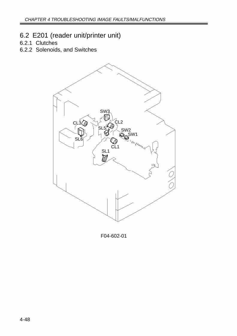
CHAPTER 4 TROUBLESHOOTING IMAGE FAULTS/MALFUNCTIONS
4-48
6.2 E201 (reader unit/printer unit)6.2.1 Clutches6.2.2 Solenoids, and Switches
F04-602-01
SL5
SL6
CL3 CL2
SW3
SW1SW2
CL1SL1
CHAPTER 4 TROUBLESHOOTING IMAGE FAULTS/MALFUNCTIONS
4-49
6.2.1 Clutches• Reader Unit
The reader unit does not have nay clutch.
• Printer UnitElectrical signal (target) Reference to generalI/O address RemarksName circuit diagram I/O indicationCL1 (DC-CON) A3-20-N P001-5Vertical path clutch 0: ON, 1: OFFCL2 (DC-CON) A3-18-N P001-6Multifeeder clutch 0: ON, 1: OFFCL3 (DC-CON) A3-20-J P001-7Developing clutch 0: ON, 1: OFF
6.2.2 Solenoids, and Switches• Reader Unit
The reader unit does not have any solenoid or switch.
• Printer UnitElectrical signal (target) Reference to generalI/O address RemarksName circuit diagram I/O indicationSL1 (DC-CON) A3-20-N P002-0Pickup DOWN solenoid 1: ON, 0: OFFSL5 (DC-CON) A3-20-J P002-3Multifeeder holding plate 1: ON, 0: OFFreleasing solenoidSL6 (DC-CON) A3-20-J P002-4Charging roller solenoid 1: ON, 0: OFFSW1 (MPWS) A3-12-BMain power switchSW2 (MPWS) A3-12-BEnvironment heater switchSW3 (MPWS) A3-14-B P008-7Front cover switch 0: open, 1: closed

CHAPTER 4 TROUBLESHOOTING IMAGE FAULTS/MALFUNCTIONS
4-50
6.2.3 Motors (1/2)
F04-602-02
M1
M2
M3
M4
M5
M6
M9 M10
M400
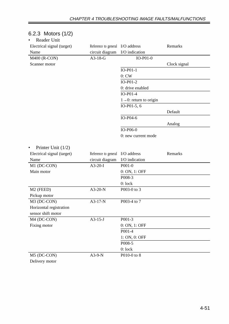
CHAPTER 4 TROUBLESHOOTING IMAGE FAULTS/MALFUNCTIONS
4-51
6.2.3 Motors (1/2)• Reader UnitElectrical signal (target) Reference to generalI/O address RemarksName circuit diagram I/O indicationM400 (R-CON) A3-18-G IO-P01-0Scanner motor Clock signal
IO-P01-10: CWIO-P01-20: drive enabledIO-P01-41→0: return to originIO-P01-5, 6
DefaultIO-P04-6
AnalogIO-P06-00: new current mode
• Printer Unit (1/2)Electrical signal (target) Reference to generalI/O address RemarksName circuit diagram I/O indicationM1 (DC-CON) A3-20-I P001-0Main motor 0: ON, 1: OFF
P008-30: lock
M2 (FEED) A3-20-N P003-0 to 3Pickup motorM3 (DC-CON) A3-17-N P003-4 to 7Horizontal registrationsensor shift motorM4 (DC-CON) A3-15-J P001-3Fixing motor 0: ON, 1: OFF
P001-41: ON, 0: OFFP008-50: lock
M5 (DC-CON) A3-9-N P010-0 to 8Delivery motor
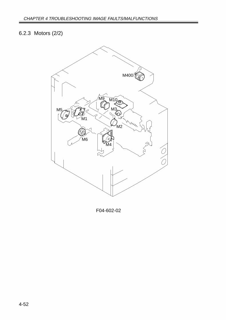
CHAPTER 4 TROUBLESHOOTING IMAGE FAULTS/MALFUNCTIONS
4-52
6.2.3 Motors (2/2)
F04-602-02
M1
M2
M3
M4
M5
M6
M9 M10
M400
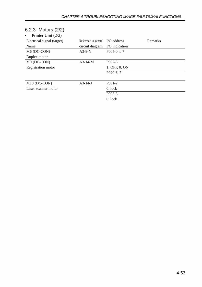
CHAPTER 4 TROUBLESHOOTING IMAGE FAULTS/MALFUNCTIONS
4-53
6.2.3 Motors (2/2)• Printer Unit (2/2)Electrical signal (target) Reference to generalI/O address RemarksName circuit diagram I/O indicationM6 (DC-CON) A3-8-N P005-0 to 7Duplex motorM9 (DC-CON) A3-14-M P002-5Registration motor 1: OFF, 0: ON
P020-6, 7
M10 (DC-CON) A3-14-J P001-2Laser scanner motor 0: lock
P008-30: lock
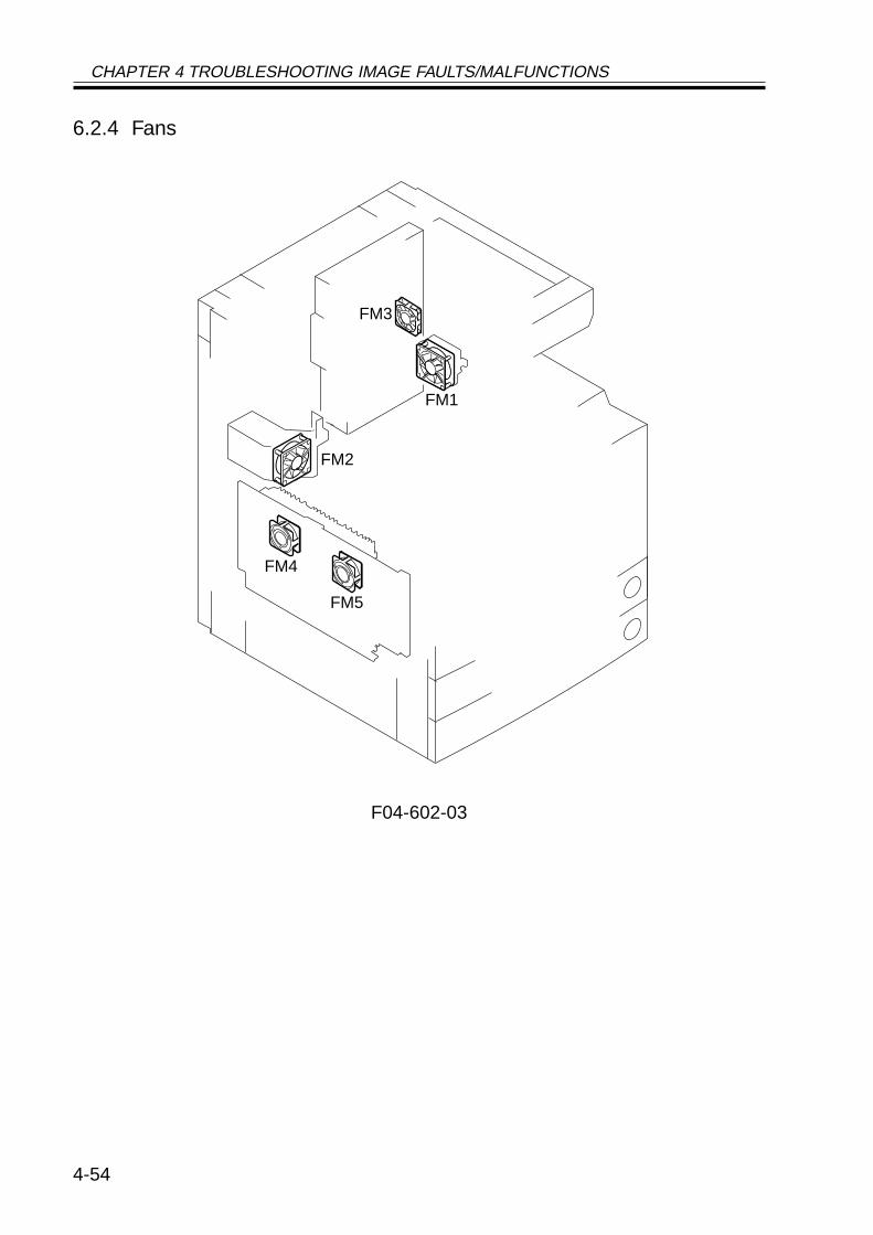
CHAPTER 4 TROUBLESHOOTING IMAGE FAULTS/MALFUNCTIONS
4-54
6.2.4 Fans
F04-602-03
FM4
FM5
FM1
FM2
FM3
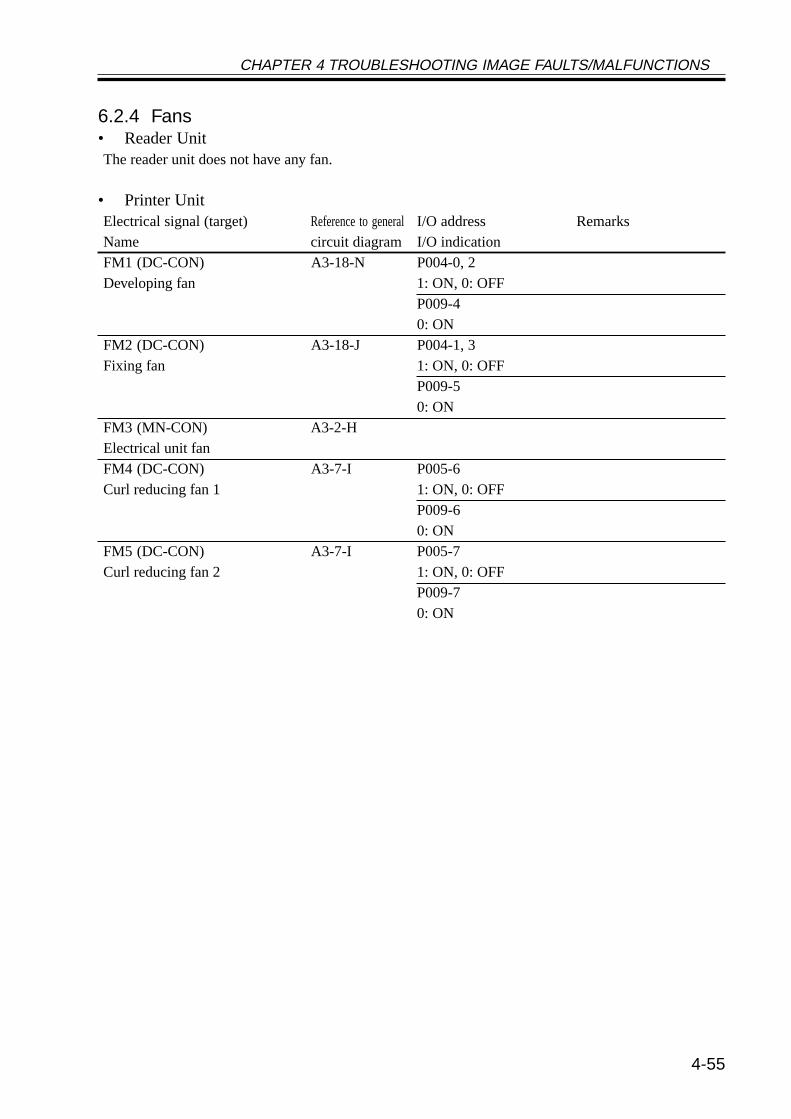
CHAPTER 4 TROUBLESHOOTING IMAGE FAULTS/MALFUNCTIONS
4-55
6.2.4 Fans• Reader UnitThe reader unit does not have any fan.
• Printer UnitElectrical signal (target) Reference to generalI/O address RemarksName circuit diagram I/O indicationFM1 (DC-CON) A3-18-N P004-0, 2Developing fan 1: ON, 0: OFF
P009-40: ON
FM2 (DC-CON) A3-18-J P004-1, 3Fixing fan 1: ON, 0: OFF
P009-50: ON
FM3 (MN-CON) A3-2-HElectrical unit fanFM4 (DC-CON) A3-7-I P005-6Curl reducing fan 1 1: ON, 0: OFF
P009-60: ON
FM5 (DC-CON) A3-7-I P005-7Curl reducing fan 2 1: ON, 0: OFF
P009-70: ON

CHAPTER 4 TROUBLESHOOTING IMAGE FAULTS/MALFUNCTIONS
4-56
6.2.5 Sensors (1/3)
F04-602-04
S5
S4
PS23
PS12
PS10
PS11
PS9PS1-6 PS22
PS8PS7PS26
PS13
S2
PS15
PS17PS18
PS16
PS400
PS401
S3
S1
VR1
SD1
BD
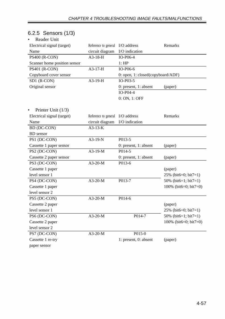
CHAPTER 4 TROUBLESHOOTING IMAGE FAULTS/MALFUNCTIONS
4-57
6.2.5 Sensors (1/3)• Reader UnitElectrical signal (target) Reference to generalI/O address RemarksName circuit diagram I/O indicationPS400 (R-CON) A3-18-H IO-P06-4Scanner home position sensor 1: HPPS401 (R-CON) A3-17-H IO-P06-6Copyboard cover sensor 0: open, 1: closed(copyboard/ADF)SD1 (R-CON) A3-19-H IO-P03-5Original sensor 0: present, 1: absent (paper)
IO-P04-40: ON, 1: OFF
• Printer Unit (1/3)Electrical signal (target) Reference to generalI/O address RemarksName circuit diagram I/O indicationBD (DC-CON) A3-13-KBD sensorPS1 (DC-CON) A3-19-N P013-5Cassette 1 paper sensor 0: present, 1: absent (paper)PS2 (DC-CON) A3-19-M P014-5Cassette 2 paper sensor 0: present, 1: absent (paper)PS3 (DC-CON) A3-20-M P013-6Cassette 1 paper (paper)level sensor 1 25% (bit6=0; bit7=1)PS4 (DC-CON) A3-20-M P013-7 50% (bit6=1; bit7=1)Cassette 1 paper 100% (bit6=0; bit7=0)level sensor 2PS5 (DC-CON) A3-20-M P014-6Cassette 2 paper (paper)level sensor 1 25% (bit6=0; bit7=1)PS6 (DC-CON) A3-20-M P014-7 50% (bit6=1; bit7=1)Cassette 2 paper 100% (bit6=0; bit7=0)level sensor 2PS7 (DC-CON) A3-20-M P015-0Cassette 1 re-try 1: present, 0: absent (paper)paper sensor

CHAPTER 4 TROUBLESHOOTING IMAGE FAULTS/MALFUNCTIONS
4-58
6.2.5 Sensors (2/3)
F04-602-04
S5
S4
PS23
PS12
PS10
PS11
PS9PS1-6 PS22
PS8PS7PS26
PS13
S2
PS15
PS17PS18
PS16
PS400
PS401
S3
S1
VR1
SD1
BD
CHAPTER 4 TROUBLESHOOTING IMAGE FAULTS/MALFUNCTIONS
4-59
6.2.5 Sensors (2/3)• Printer Unit (2/3)Electrical signal (target) Reference to generalI/O address RemarksName circuit diagram I/O indicationPS8 (DC-CON) A3-20-M P015-1Cassette 2 re-try paper sensor 1: present, 0: absent (paper)PS9 (DC-CON) A3-16-N P015-2Pre-registration paper sensor 1: present, 0: absent (paper)PS10 (DC-CON) A3-16-N P015-3Registration paper sensor 1: present, 0: absent (paper)PS11 (DC-CON) A3-16-N P015-4Horizontal registration 0: present,1: absent (paper)paper sensorPS12 (DC-CON) A3-16-I P025-7Image leading edge sensor 1: present, 0: absent (paper)PS13 (DC-CON) A3-8-J P015-5Fixing/feeding sensor 0: present,1: absent (paper)PS15 (DC-CON) A3-8-N P015-6No. 1 delivery sensor 1: present, 0: absent (paper)PS16 (DC-CON) A3-9-N P015-7No. 1 delivery full sensor 1: present, 0: absent (paper)PS17 (DC-CON) A3-7-N P016-0Duplex unit inlet paper sensor 0: present,1: absent (paper)PS18 (DC-CON) A3-7-N P016-1Duplex unit outlet paper sensor 0: present,1: absent (paper)PS22 (DC-CON) A3-15-N P016-5Multifeeder paper sensor 0: present,1: absent (paper)PS23 (DC-CON) A3-15-N P016-6Right cover open/closed sensor 1: open, 0: closedPS26 (DC-CON) A3-8-J P021-0Fixing film sensorS1 (DC-CON) A3-18-N P008-0Toner sensor 1: present, 0: absent (toner)S2 (DC-CON) A3-6-I P008-2Waste toner case full sensor 1: full (waste toner)S3 (DC-CON) A3-17-N P023-4, P33 (humidity)Environment sensor A/D
P023-5, P34 (room temperature)A/D
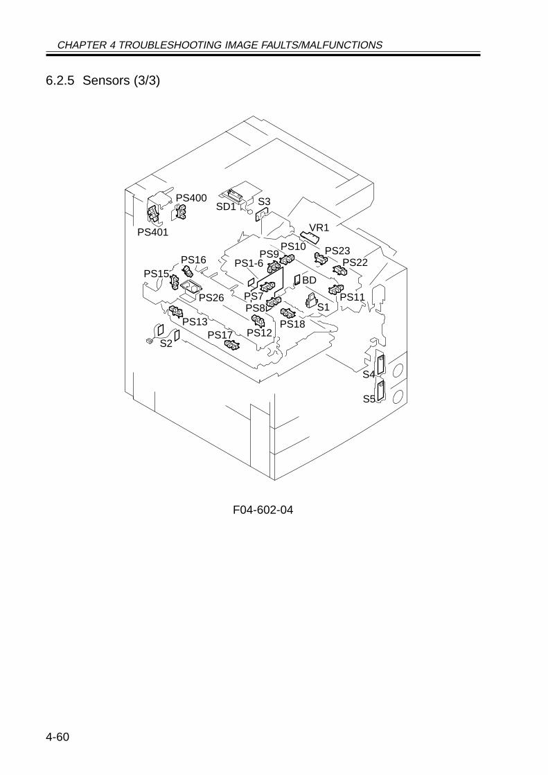
CHAPTER 4 TROUBLESHOOTING IMAGE FAULTS/MALFUNCTIONS
4-60
6.2.5 Sensors (3/3)
F04-602-04
S5
S4
PS23
PS12
PS10
PS11
PS9PS1-6 PS22
PS8PS7PS26
PS13
S2
PS15
PS17PS18
PS16
PS400
PS401
S3
S1
VR1
SD1
BD

CHAPTER 4 TROUBLESHOOTING IMAGE FAULTS/MALFUNCTIONS
4-61
6.2.5 Sensors (3/3)Electrical signal (target) Reference to generalI/O address RemarksName circuit diagram I/O indicationS4 (DC-CON) A3-17-J P013-0 to 4Cassette 1 size sensorS5 (DC-CON) A3-16-J P014-0 to 4Cassette 2 size sensorVR1 (DC-CON) A3-18-M P023-2, P31Multifeeder paper width sensor A/D
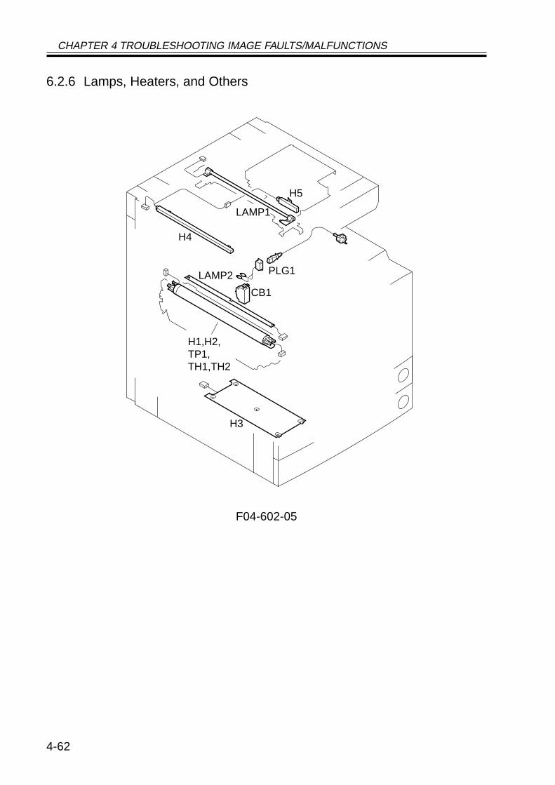
CHAPTER 4 TROUBLESHOOTING IMAGE FAULTS/MALFUNCTIONS
4-62
6.2.6 Lamps, Heaters, and Others
F04-602-05
LAMP1
H5
H4
CB1
PLG1LAMP2
H3
H1,H2,TP1,TH1,TH2
CHAPTER 4 TROUBLESHOOTING IMAGE FAULTS/MALFUNCTIONS
4-63
6.2.6 Lamps, Heaters, and Others• Reader UnitElectrical signal (target) Reference to generalI/O address RemarksName circuit diagram I/O indicationH4 (MPWS) A3-9-AMirror heater (accessory)H5 (MPWS) A3-9-ALens heater (accessory)LAMP1 (R-CON) A3-17-HScanning lanp
• Printer UnitElectrical signal (target) Reference to generalI/O address RemarksName circuit diagram I/O indicationCB1 (MPWS) A3-14-ALeakage breakerH1 (MPWS) A3-9-CFixing main heaterH2 (MPWS) A3-9-BFixing sub heaterH3 (MPWS) A3-9-B (accessory)Cassette heaterLAMP2 (DC-CON) A3-14-J P001-1Pre-exposure lamp 1: ON, 0: OFFPLG1 (Switch PCB) A3-14-APower supply cordTH1 (MPWS) A3-12-J P023-0, P29Main thermistor A/DTH2 (DC-CON) A3-12-J P023-1, P30Sub thermistor A/DTP1 (DC-CON) A3-9-BThermal switch
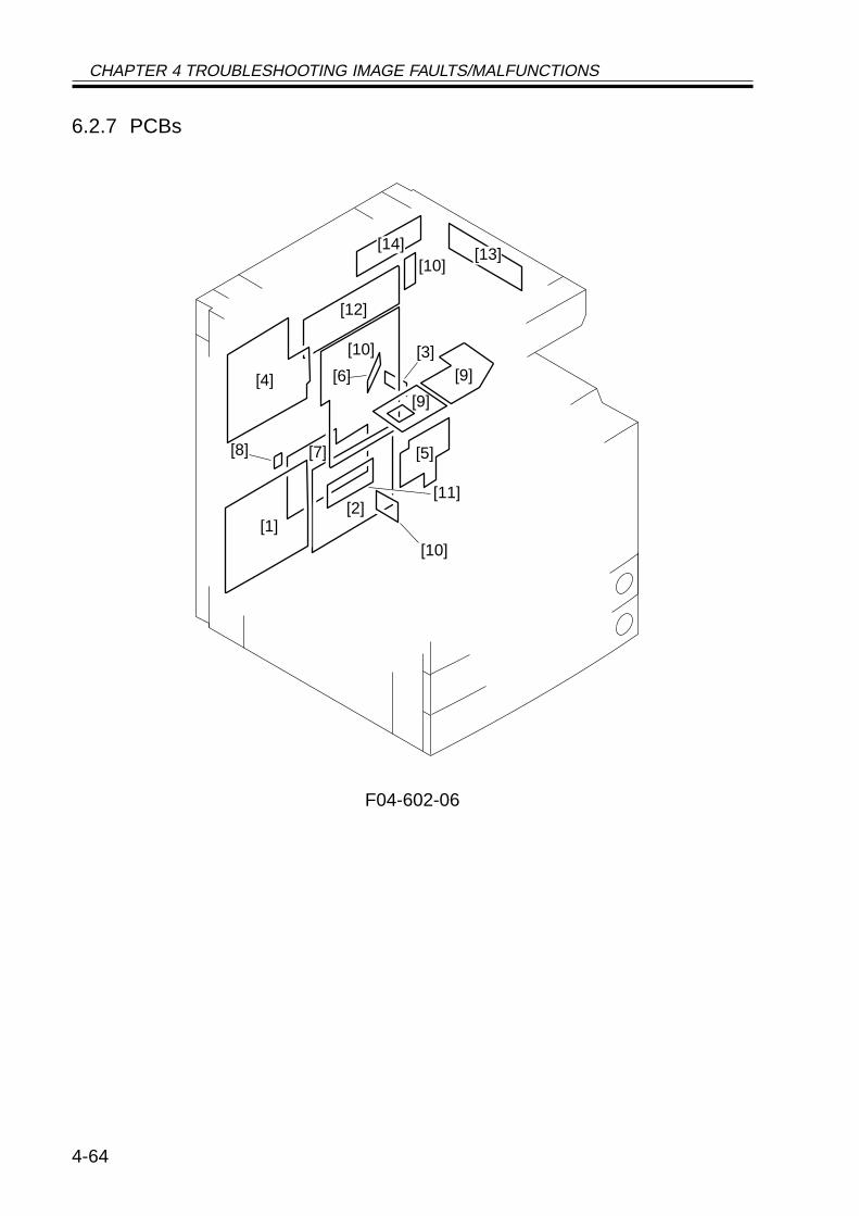
CHAPTER 4 TROUBLESHOOTING IMAGE FAULTS/MALFUNCTIONS
4-64
6.2.7 PCBs
F04-602-06
[3]
[11]
[9]
[9]
[5]
[13]
[2]
[7]
[6]
[10]
[10]
[8]
[1]
[12]
[10]
[4]
[14]
CHAPTER 4 TROUBLESHOOTING IMAGE FAULTS/MALFUNCTIONS
4-65
6.2.7 PCBs• Reader UnitRef. Description RemarksName[12] Controls the reader unit/ADF.Reader controller PCB[13] Drives the CCD.CCD PCB[14] Controls the scanning lamp.Inverter PCB
• Printer UnitRef. Description RemarksName[1] Controls the generation ofComposite power supply PCB high voltage.[2] Controls the supply of DC .Main power supply PCB power[3] Controls the main powerSwitch PCB switch/heater.[4] Controls the printer unit.DC controller PCB[5] Controls the pickup assembly.Pickup PCB[6] Controls laser drive.Laser driver PCB[7] Controls the supply of powerAccessories power supply PCB to the finisher/paper deck.[8] Detects temperature of the drum.Drum sensor PCB[9] Controls keys and LEDs.Control panel PCB[10] Controls digital image Includes counter PCB,Main controller PCB processing/system. soft ID PCB, Centronics PCB.[11] Controls the DC-DC converter. 200V model only.Thermistor separation powersupply PCB
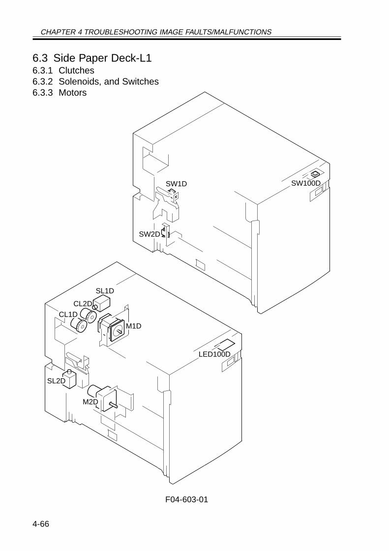
CHAPTER 4 TROUBLESHOOTING IMAGE FAULTS/MALFUNCTIONS
4-66
6.3 Side Paper Deck-L16.3.1 Clutches6.3.2 Solenoids, and Switches6.3.3 Motors
F04-603-01
M1D
SL2D
M2D
SL1D
LED100D
CL2D
CL1D
SW2D
SW1D SW100D
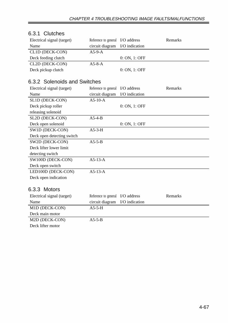
CHAPTER 4 TROUBLESHOOTING IMAGE FAULTS/MALFUNCTIONS
4-67
6.3.1 ClutchesElectrical signal (target) Reference to generalI/O address RemarksName circuit diagram I/O indicationCL1D (DECK-CON) A5-9-ADeck feeding clutch 0: ON, 1: OFFCL2D (DECK-CON) A5-8-ADeck pickup clutch 0: ON, 1: OFF
6.3.2 Solenoids and SwitchesElectrical signal (target) Reference to generalI/O address RemarksName circuit diagram I/O indicationSL1D (DECK-CON) A5-10-ADeck pickup roller 0: ON, 1: OFFreleasing solenoidSL2D (DECK-CON) A5-4-BDeck open solenoid 0: ON, 1: OFFSW1D (DECK-CON) A5-3-HDeck open detecting switchSW2D (DECK-CON) A5-5-BDeck lifter lower limitdetecting switchSW100D (DECK-CON) A5-13-ADeck open switchLED100D (DECK-CON) A5-13-ADeck open indication
6.3.3 MotorsElectrical signal (target) Reference to generalI/O address RemarksName circuit diagram I/O indicationM1D (DECK-CON) A5-5-HDeck main motorM2D (DECK-CON) A5-5-BDeck lifter motor
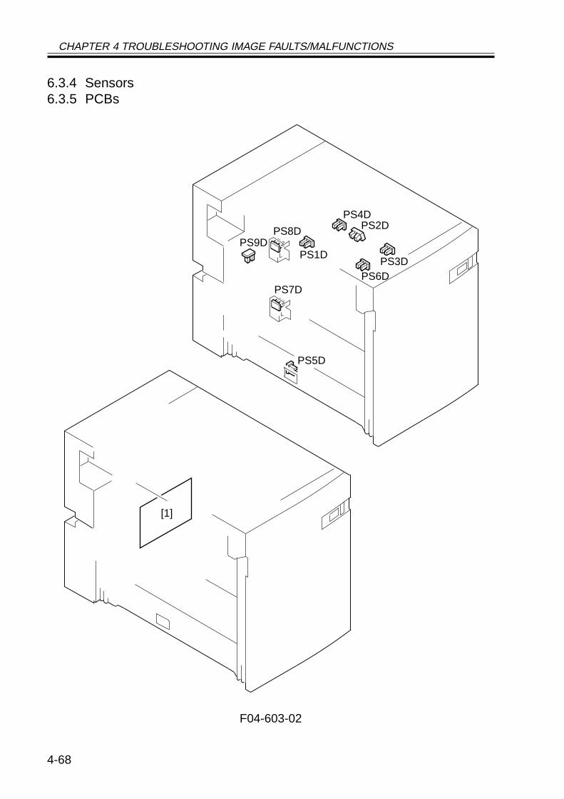
CHAPTER 4 TROUBLESHOOTING IMAGE FAULTS/MALFUNCTIONS
4-68
6.3.4 Sensors6.3.5 PCBs
F04-603-02
[1]
PS6D
PS5D
PS1D
PS4DPS2D
PS3D
PS8DPS9D
PS7D
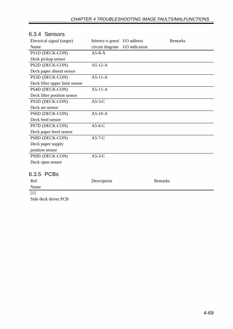
CHAPTER 4 TROUBLESHOOTING IMAGE FAULTS/MALFUNCTIONS
4-69
6.3.4 SensorsElectrical signal (target) Reference to generalI/O address RemarksName circuit diagram I/O indicationPS1D (DECK-CON) A5-8-ADeck pickup sensorPS2D (DECK-CON) A5-12-ADeck paper absent sensorPS3D (DECK-CON) A5-11-ADeck lifter upper limit sensorPS4D (DECK-CON) A5-11-ADeck lifter position sensorPS5D (DECK-CON) A5-3-CDeck set sensorPS6D (DECK-CON) A5-10-ADeck feed sensorPS7D (DECK-CON) A5-6-CDeck paper level sensorPS8D (DECK-CON) A5-7-CDeck paper supplyposition sensorPS9D (DECK-CON) A5-3-CDeck open sensor
6.3.5 PCBsRef. Description RemarksName[1]Side deck driver PCB
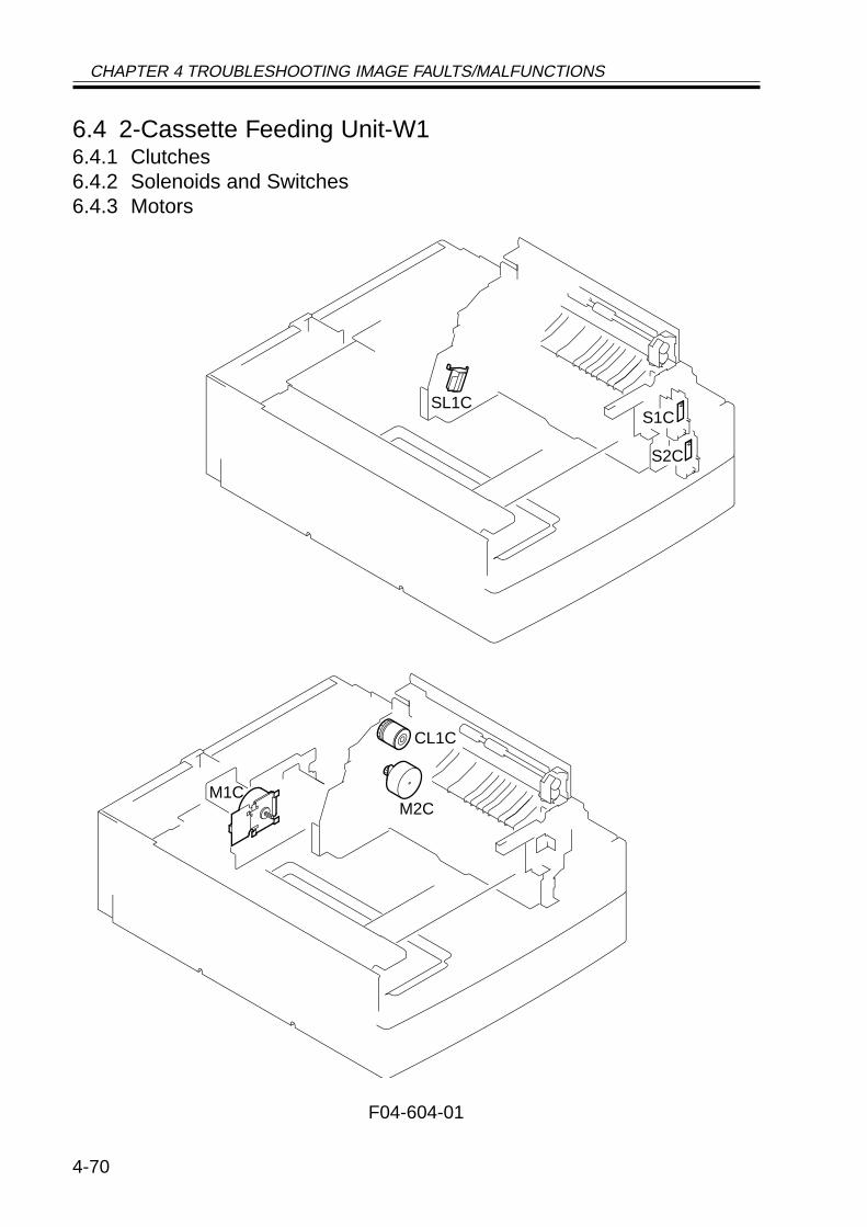
CHAPTER 4 TROUBLESHOOTING IMAGE FAULTS/MALFUNCTIONS
4-70
6.4 2-Cassette Feeding Unit-W16.4.1 Clutches6.4.2 Solenoids and Switches6.4.3 Motors
F04-604-01
S1C
S2C
M1CM2C
SL1C
CL1C
CHAPTER 4 TROUBLESHOOTING IMAGE FAULTS/MALFUNCTIONS
4-71
6.4.1 ClutchesElectrical signal (target) Reference to generalI/O address RemarksName circuit diagram I/O indicationCL1C (PEDE-FEED) A6-11-FVertical path roller clutch 0: ON, 1: OFF
6.4.2 Solenoids and SwitchesElectrical signal (target) Reference to generalI/O address RemarksName circuit diagram I/O indicationSL1C (PEDE-FEED) A6-11-FPickup roller DOWN solenoid 0: ON, 1: OFFS1C (PEDE-CON) A6-7-ACassette 3 size detecting switchS2C (PEDE-CON) A6-6-ACassette 4 size detecting switch
6.4.3 MotorsElectrical signal (target) Reference to generalI/O address RemarksName circuit diagram I/O indicationM1C (PEDE-CON) A6-2-EPedestal main motorM2C (PEDE-FEED) A6-11-GCassette pickup motor
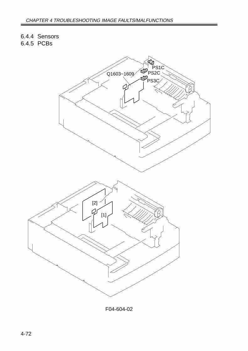
CHAPTER 4 TROUBLESHOOTING IMAGE FAULTS/MALFUNCTIONS
4-72
6.4.4 Sensors6.4.5 PCBs
F04-604-02
[2]
[1]
PS1CPS2C
PS3C
Q1603~1609
CHAPTER 4 TROUBLESHOOTING IMAGE FAULTS/MALFUNCTIONS
4-73
6.4.4 SensorsElectrical signal (target) Reference to generalI/O address RemarksName circuit diagram I/O indicationPS1C (PEDE-CON) A6-6-HRight cover open/closed sensorPS2C (PEDE-FEED) A6-11-DCassette 3 re-try paper sensorPS3C (PEDE-FEED) A6-11-CCassette 4 re-try paper sensorQ1603 (PEDE-CON) A6-9-EVertical path paper sensorQ1604 (PEDE-FEED) A6-12-ECassette 3 paper sensorQ1605 (PEDE-CON) A6-9-ECassette 4 paper sensorQ1606 (PEDE-CON) A6-9-ECassette 3 paper level sensor 0Q1607 (PEDE-CON) A6-9-ECassette 3 paper level sensor 1Q1608 (PEDE-CON) A6-9-ECassette 4 paper level sensor 0Q1609 (PEDE-CON) A6-9-ECassette 4 paper level sensor 1
6.4.5 PCBsRef. Description RemarksName[1] Controls the pickup assembly.2-cassette pedestal pickup PCB[2] Controls the paper deck.Pedestal controller PCB
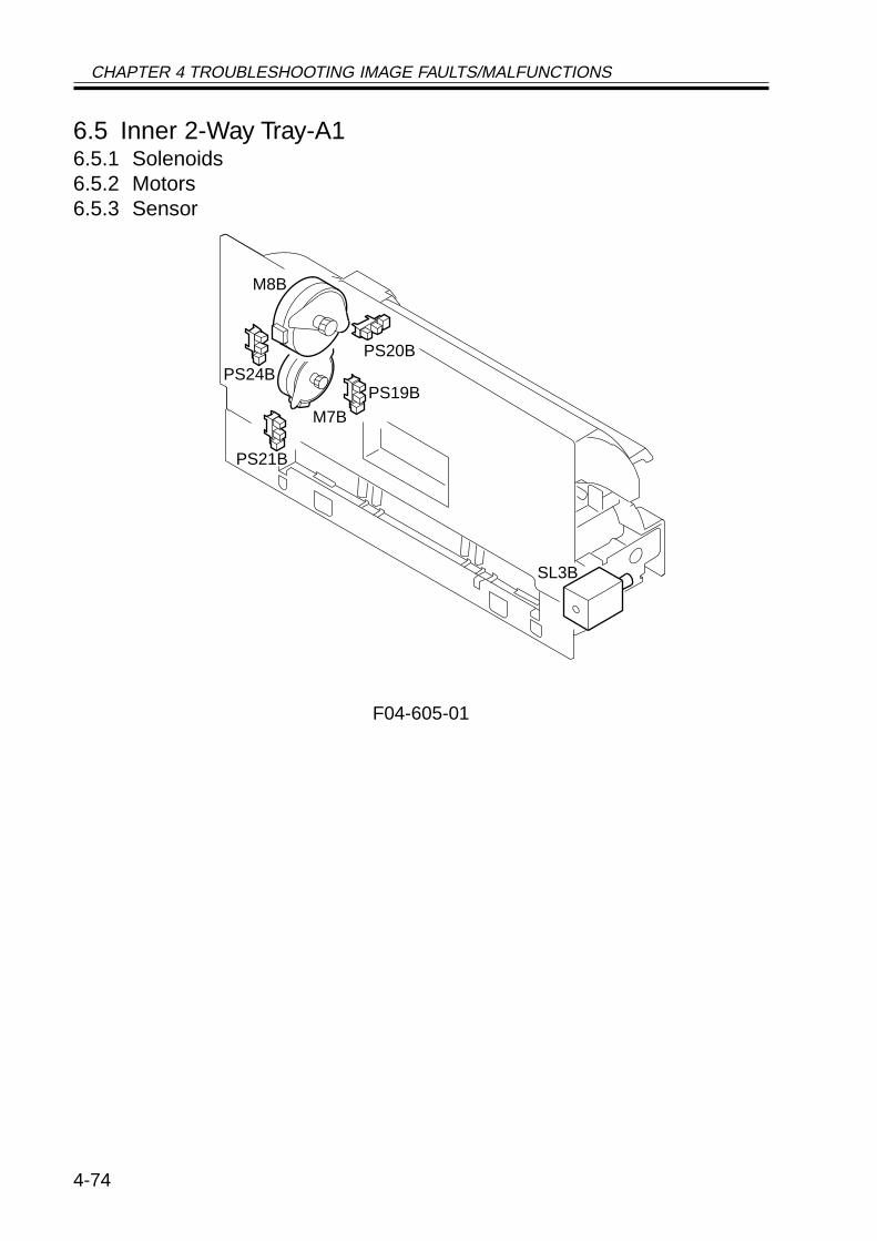
CHAPTER 4 TROUBLESHOOTING IMAGE FAULTS/MALFUNCTIONS
4-74
6.5 Inner 2-Way Tray-A16.5.1 Solenoids6.5.2 Motors6.5.3 Sensor
F04-605-01
PS24BPS20B
PS19B
PS21B
M8B
M7B
SL3B
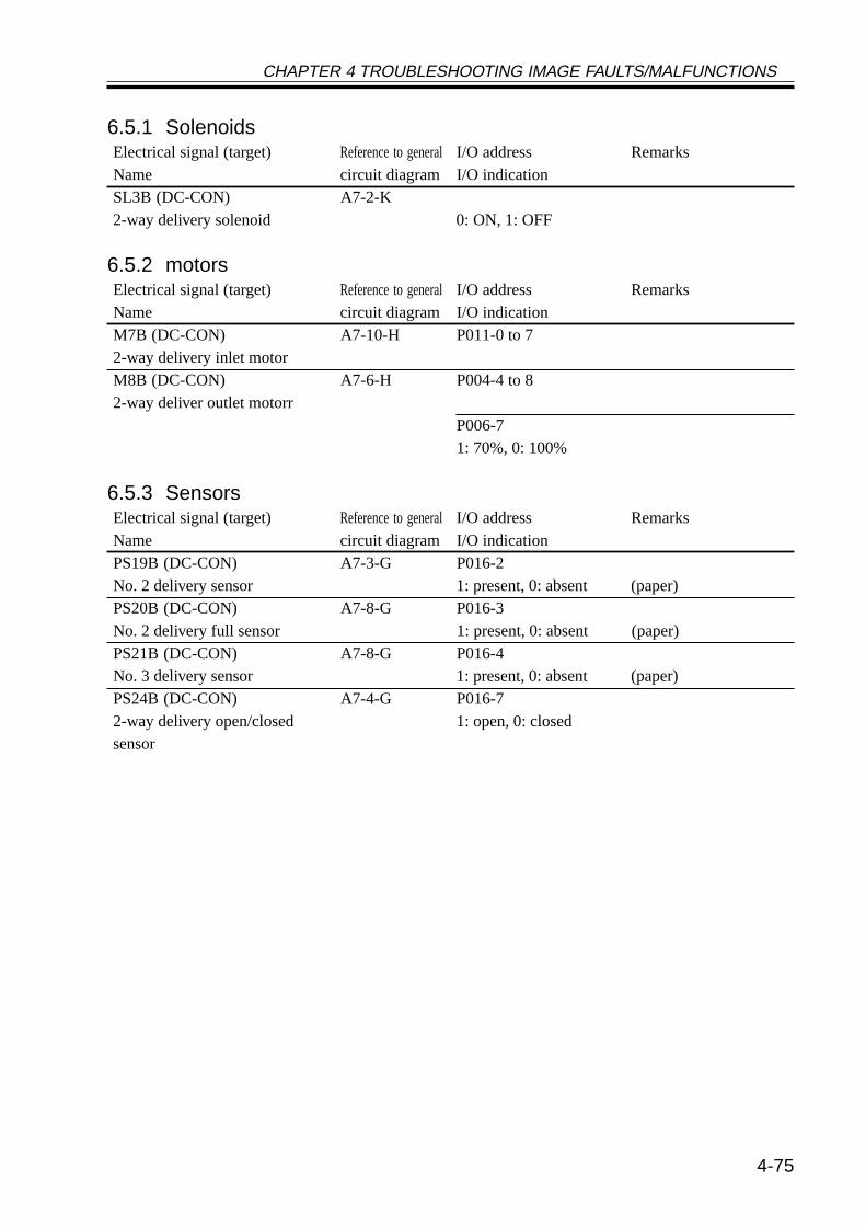
CHAPTER 4 TROUBLESHOOTING IMAGE FAULTS/MALFUNCTIONS
4-75
6.5.1 SolenoidsElectrical signal (target) Reference to generalI/O address RemarksName circuit diagram I/O indicationSL3B (DC-CON) A7-2-K2-way delivery solenoid 0: ON, 1: OFF
6.5.2 motorsElectrical signal (target) Reference to generalI/O address RemarksName circuit diagram I/O indicationM7B (DC-CON) A7-10-H P011-0 to 72-way delivery inlet motorM8B (DC-CON) A7-6-H P004-4 to 82-way deliver outlet motorr
P006-71: 70%, 0: 100%
6.5.3 SensorsElectrical signal (target) Reference to generalI/O address RemarksName circuit diagram I/O indicationPS19B (DC-CON) A7-3-G P016-2No. 2 delivery sensor 1: present, 0: absent (paper)PS20B (DC-CON) A7-8-G P016-3No. 2 delivery full sensor 1: present, 0: absent (paper)PS21B (DC-CON) A7-8-G P016-4No. 3 delivery sensor 1: present, 0: absent (paper)PS24B (DC-CON) A7-4-G P016-72-way delivery open/closed 1: open, 0: closedsensor
CHAPTER 4 TROUBLESHOOTING IMAGE FAULTS/MALFUNCTIONS
4-76
6.6 Super G3 FAX Board-J16.6.1 Others6.6.2 PCBs
F04-606-01
SP1
[1]
[2]
[3] [4]
[5]
CHAPTER 4 TROUBLESHOOTING IMAGE FAULTS/MALFUNCTIONS
4-77
6.6.1 OthersElectrical signal (target) Reference to generalI/O address RemarksName circuit diagram I/O indicationSP1 (FAX-CON) A3-1-ESpeaker
6.6.2 PCBsRef. Description RemarksName[1] Controls the fax system.G3 FAX control PCB[2] Serves as an interface between 100V and 120V models useNCU PCB telephone line and fax system. different interfaces.[3] Connects a modular cable. 100V and 120V models useG3 modular PCB different interfaces.[4] Stores firmware for the fax 16M bitDIMM system.[5] Generates a pseudo CI signal. 100VPseudo CI PCB[6] Detects off-hook state of the 120VOff-hook detection PCB telephone
CHAPTER 4 TROUBLESHOOTING IMAGE FAULTS/MALFUNCTIONS
4-78
6.7 Variable Resistors (VR), Light-Emitting Diodes, and CheckPins by PCB
Of the variable resistors, light-emitting diodes, and switches used in the machine, thoseneeded for service work in the field are discussed:
1. Some LEDs emit dim light when they are off because of leakage cur-rent; this is a normal condition, and must be kept in mind.
2. VRs that may be used in the field:
VRs that must not be used in the field:
Do not touch those VRs and check pins not discussed herein; they are forexclusive use in the factory, and require high accuracy and special instru-ments.
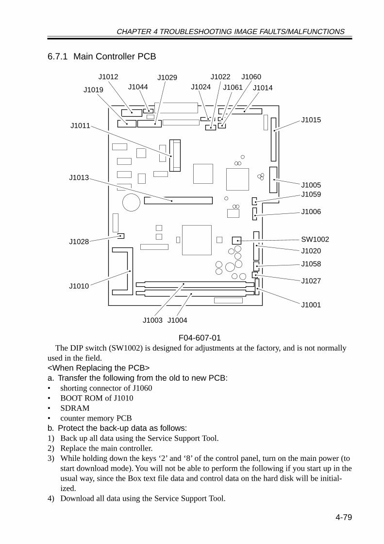
CHAPTER 4 TROUBLESHOOTING IMAGE FAULTS/MALFUNCTIONS
4-79
6.7.1 Main Controller PCB
F04-607-01The DIP switch (SW1002) is designed for adjustments at the factory, and is not normally
used in the field.<When Replacing the PCB>a. Transfer the following from the old to new PCB:• shorting connector of J1060• BOOT ROM of J1010• SDRAM• counter memory PCBb. Protect the back-up data as follows:1) Back up all data using the Service Support Tool.2) Replace the main controller.3) While holding down the keys ‘2’ and ‘8’ of the control panel, turn on the main power (to
start download mode). You will not be able to perform the following if you start up in theusual way, since the Box text file data and control data on the hard disk will be initial-ized.
4) Download all data using the Service Support Tool.
J1019 J1044 J1029
J1024 J1061 J1014
J1015
J1005J1013
J1011
J1028
J1010
J1003 J1004
J1059
J1006
SW1002
J1020
J1058
J1027
J1001
J1012 J1022 J1060
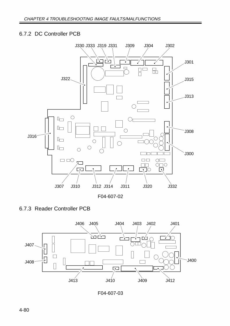
CHAPTER 4 TROUBLESHOOTING IMAGE FAULTS/MALFUNCTIONS
4-80
6.7.2 DC Controller PCB
F04-607-02
6.7.3 Reader Controller PCB
F04-607-03
J330
J322
J333 J319 J331 J309 J304 J302
J301
J315
J313
J308
J300
J332J320J311J314J312J310J307
J316
J400
J412J409J410J413
J408
J407
J406 J405 J404 J403 J402 J401
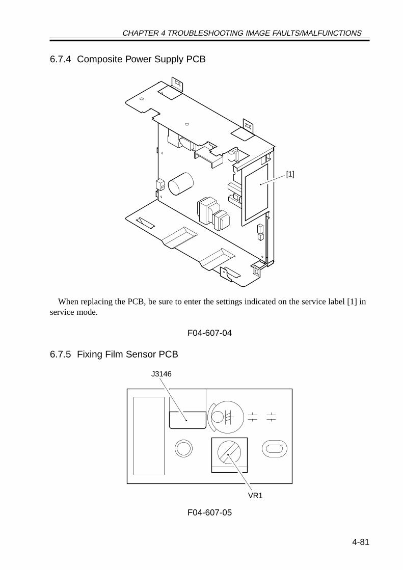
CHAPTER 4 TROUBLESHOOTING IMAGE FAULTS/MALFUNCTIONS
4-81
6.7.4 Composite Power Supply PCB
When replacing the PCB, be sure to enter the settings indicated on the service label [1] inservice mode.
F04-607-04
6.7.5 Fixing Film Sensor PCB
F04-607-05
[1]
J3146
VR1

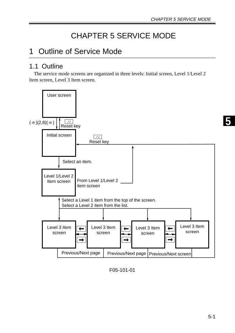
CHAPTER 5 SERVICE MODE
5-1
CHAPTER 5 SERVICE MODE
1 Outline of Service Mode
1.1 OutlineThe service mode screens are organized in three levels: Initial screen, Level 1/Level 2
Item screen, Level 3 Item screen.
F05-101-01
Initial screen
Level 1/Level 2Item screen
Level 3 Itemscreen
Level 3 Itemscreen
Level 3 Itemscreen
User screen
From Level 1/Level 2item screen
Reset key
Previous/Next screenPrevious/Next pagePrevious/Next page
( )(2,8)( )
Reset key
Select a Level 1 item from the top of the screen.Select a Level 2 item from the list.
Level 3 Itemscreen
Select an item.
5
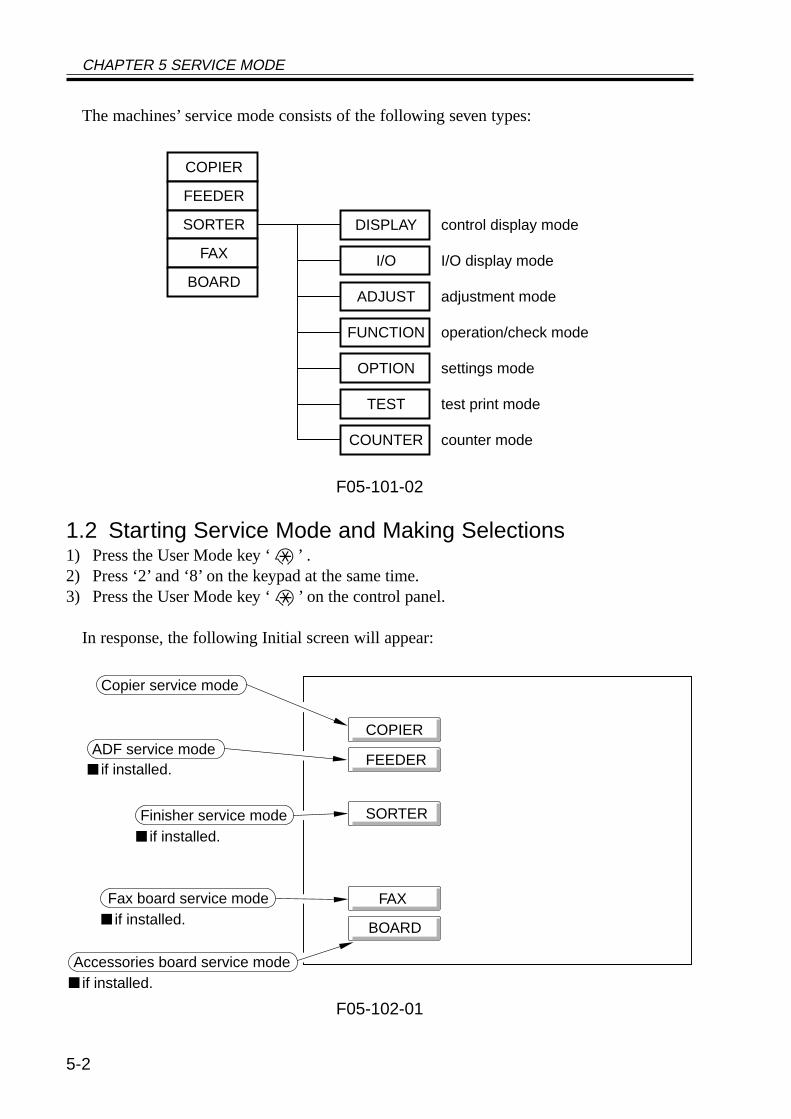
CHAPTER 5 SERVICE MODE
5-2
The machines’ service mode consists of the following seven types:
F05-101-02
1.2 Starting Service Mode and Making Selections1) Press the User Mode key ‘ ’ .2) Press ‘2’ and ‘8’ on the keypad at the same time.3) Press the User Mode key ‘ ’ on the control panel.
In response, the following Initial screen will appear:
F05-102-01
COPIER
FEEDER
SORTER
FAX
BOARD
DISPLAY
I/O
ADJUST
FUNCTION
OPTION
TEST
COUNTER
control display mode
I/O display mode
adjustment mode
operation/check mode
settings mode
test print mode
counter mode
FAX
COPIER
FEEDER
SORTER
FAX
BOARD
if installed.
if installed.
if installed.
Copier service mode
ADF service mode
Finisher service mode
if installed.Fax board service mode
Accessories board service mode
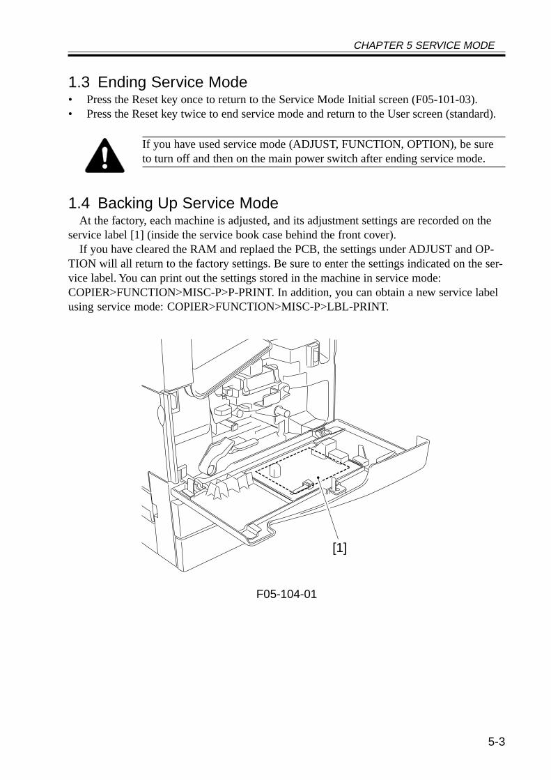
CHAPTER 5 SERVICE MODE
5-3
1.3 Ending Service Mode• Press the Reset key once to return to the Service Mode Initial screen (F05-101-03).• Press the Reset key twice to end service mode and return to the User screen (standard).
If you have used service mode (ADJUST, FUNCTION, OPTION), be sureto turn off and then on the main power switch after ending service mode.
1.4 Backing Up Service ModeAt the factory, each machine is adjusted, and its adjustment settings are recorded on the
service label [1] (inside the service book case behind the front cover).If you have cleared the RAM and replaed the PCB, the settings under ADJUST and OP-
TION will all return to the factory settings. Be sure to enter the settings indicated on the ser-vice label. You can print out the settings stored in the machine in service mode:COPIER>FUNCTION>MISC-P>P-PRINT. In addition, you can obtain a new service labelusing service mode: COPIER>FUNCTION>MISC-P>LBL-PRINT.
F05-104-01
[1]
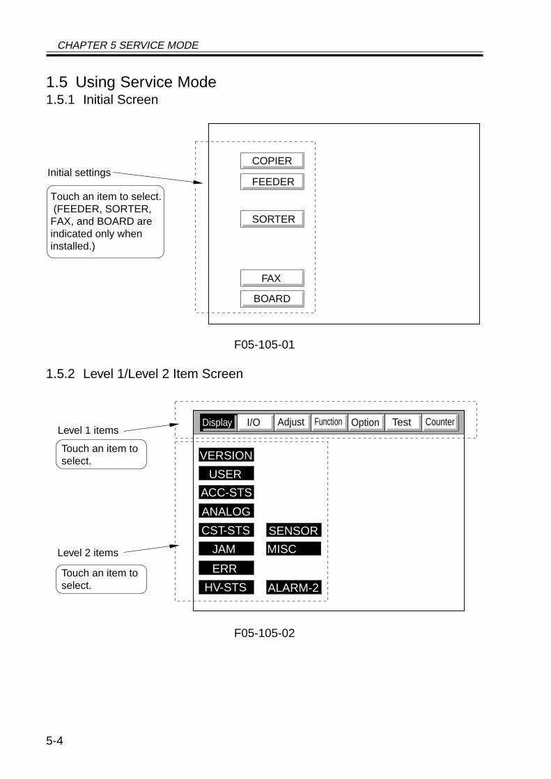
CHAPTER 5 SERVICE MODE
5-4
1.5 Using Service Mode1.5.1 Initial Screen
F05-105-01
1.5.2 Level 1/Level 2 Item Screen
F05-105-02
FAX
COPIER
FEEDER
SORTER
FAX
BOARD
Initial settings
Touch an item to select. (FEEDER, SORTER, FAX, and BOARD are indicated only when installed.)
CounterTestOptionFunctionAdjustI/ODisplay
VERSION
USER
ACC-STS
ANALOG
CST-STS
JAM MISC
ERR
HV-STS
SENSOR
ALARM-2
Level 1 items
Touch an item toselect.
Level 2 items
Touch an item toselect.
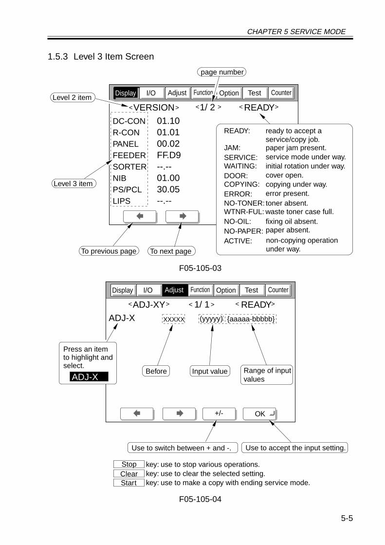
CHAPTER 5 SERVICE MODE
5-5
1.5.3 Level 3 Item Screen
F05-105-03
F05-105-04
CounterTestOptionFunctionAdjustI/ODisplay
VERSION 1/ 2 READY
DC-CONR-CONPANELFEEDERSORTERNIBPS/PCLLIPS
01.1001.0100.02FF.D9--.--01.0030.05--.--
< > < > < >
page number
To previous page To next page
Level 2 item
Level 3 item
READY:
JAM:SERVICE:WAITING:DOOR:COPYING:ERROR:NO-TONER:WTNR-FUL:NO-OIL:NO-PAPER:ACTIVE:
ready to accept aservice/copy job.paper jam present.
initial rotation under way.cover open.copying under way.error present.toner absent.
fixing oil absent.paper absent.non-copying operationunder way.
waste toner case full.
service mode under way.
CounterTestOptionFunctionI/O
ADJ-XY 1/ 1 READY
ADJ-X
< > < > < >
+/- OK
Display Adjust
XXXXX (yyyyy) aaaaa-bbbbb
Before Input value Range of inputvalues
Use to accept the input setting.Use to switch between + and -.
Press an itemto highlight andselect.
ADJ-X
key: use to stop various operations.key: use to clear the selected setting.key: use to make a copy with ending service mode.
Stop Clear Start
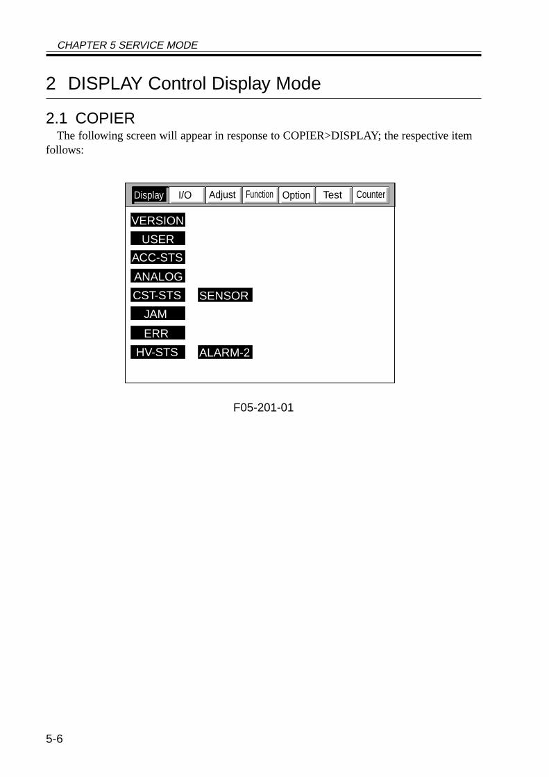
CHAPTER 5 SERVICE MODE
5-6
2 DISPLAY Control Display Mode
2.1 COPIERThe following screen will appear in response to COPIER>DISPLAY; the respective item
follows:
F05-201-01
CounterTestOptionFunctionAdjustI/ODisplay
VERSION
USER
ACC-STS
ANALOG
CST-STS
JAM
ERR
HV-STS
SENSOR
ALARM-2
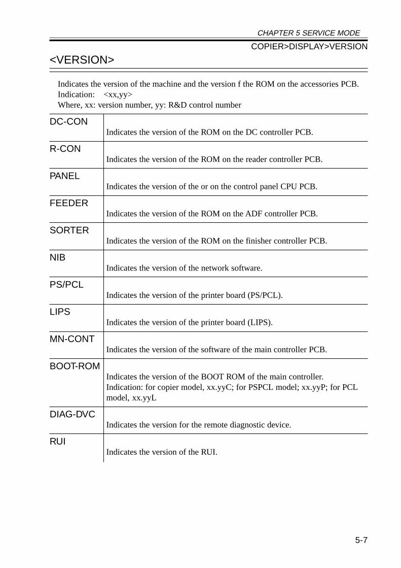
CHAPTER 5 SERVICE MODE
5-7
<VERSION>
Indicates the version of the machine and the version f the ROM on the accessories PCB.Indication: <xx,yy>Where, xx: version number, yy: R&D control number
DC-CONIndicates the version of the ROM on the DC controller PCB.
R-CONIndicates the version of the ROM on the reader controller PCB.
PANELIndicates the version of the or on the control panel CPU PCB.
FEEDERIndicates the version of the ROM on the ADF controller PCB.
SORTERIndicates the version of the ROM on the finisher controller PCB.
NIBIndicates the version of the network software.
PS/PCLIndicates the version of the printer board (PS/PCL).
LIPSIndicates the version of the printer board (LIPS).
MN-CONTIndicates the version of the software of the main controller PCB.
BOOT-ROMIndicates the version of the BOOT ROM of the main controller.Indication: for copier model, xx.yyC; for PSPCL model; xx.yyP; for PCLmodel, xx.yyL
DIAG-DVCIndicates the version for the remote diagnostic device.
RUIIndicates the version of the RUI.
COPIER>DISPLAY>VERSION
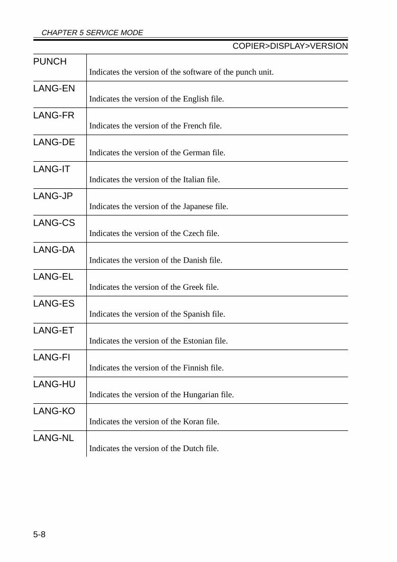
CHAPTER 5 SERVICE MODE
5-8
PUNCHIndicates the version of the software of the punch unit.
LANG-ENIndicates the version of the English file.
LANG-FRIndicates the version of the French file.
LANG-DEIndicates the version of the German file.
LANG-ITIndicates the version of the Italian file.
LANG-JPIndicates the version of the Japanese file.
LANG-CSIndicates the version of the Czech file.
LANG-DAIndicates the version of the Danish file.
LANG-ELIndicates the version of the Greek file.
LANG-ESIndicates the version of the Spanish file.
LANG-ETIndicates the version of the Estonian file.
LANG-FIIndicates the version of the Finnish file.
LANG-HUIndicates the version of the Hungarian file.
LANG-KOIndicates the version of the Koran file.
LANG-NLIndicates the version of the Dutch file.
COPIER>DISPLAY>VERSION
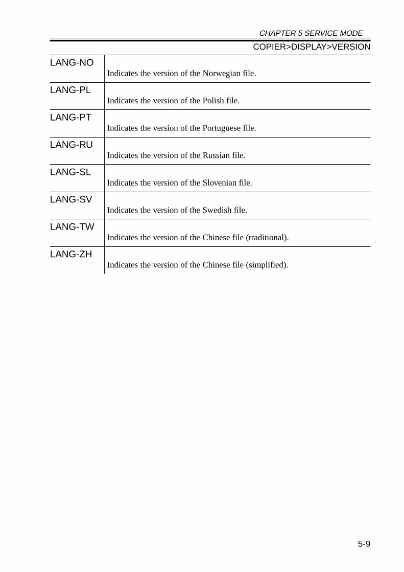
CHAPTER 5 SERVICE MODE
5-9
LANG-NOIndicates the version of the Norwegian file.
LANG-PLIndicates the version of the Polish file.
LANG-PTIndicates the version of the Portuguese file.
LANG-RUIndicates the version of the Russian file.
LANG-SLIndicates the version of the Slovenian file.
LANG-SVIndicates the version of the Swedish file.
LANG-TWIndicates the version of the Chinese file (traditional).
LANG-ZHIndicates the version of the Chinese file (simplified).
COPIER>DISPLAY>VERSION
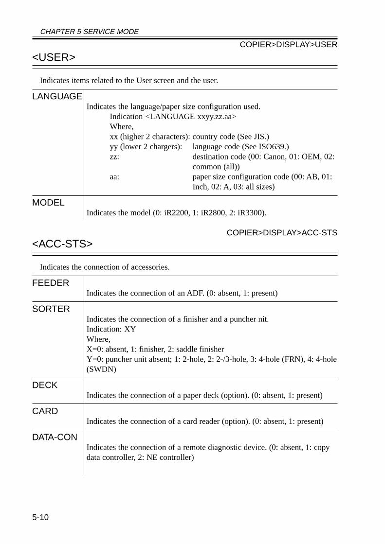
CHAPTER 5 SERVICE MODE
5-10
<USER>
Indicates items related to the User screen and the user.
LANGUAGEIndicates the language/paper size configuration used.
Indication <LANGUAGE xxyy.zz.aa>Where,xx (higher 2 characters): country code (See JIS.)yy (lower 2 chargers): language code (See ISO639.)zz: destination code (00: Canon, 01: OEM, 02:
common (all))aa: paper size configuration code (00: AB, 01:
Inch, 02: A, 03: all sizes)
MODELIndicates the model (0: iR2200, 1: iR2800, 2: iR3300).
COPIER>DISPLAY>ACC-STS
<ACC-STS>
Indicates the connection of accessories.
FEEDERIndicates the connection of an ADF. (0: absent, 1: present)
SORTERIndicates the connection of a finisher and a puncher nit.Indication: XYWhere,X=0: absent, 1: finisher, 2: saddle finisherY=0: puncher unit absent; 1: 2-hole, 2: 2-/3-hole, 3: 4-hole (FRN), 4: 4-hole(SWDN)
DECKIndicates the connection of a paper deck (option). (0: absent, 1: present)
CARDIndicates the connection of a card reader (option). (0: absent, 1: present)
DATA-CONIndicates the connection of a remote diagnostic device. (0: absent, 1: copydata controller, 2: NE controller)
COPIER>DISPLAY>USER
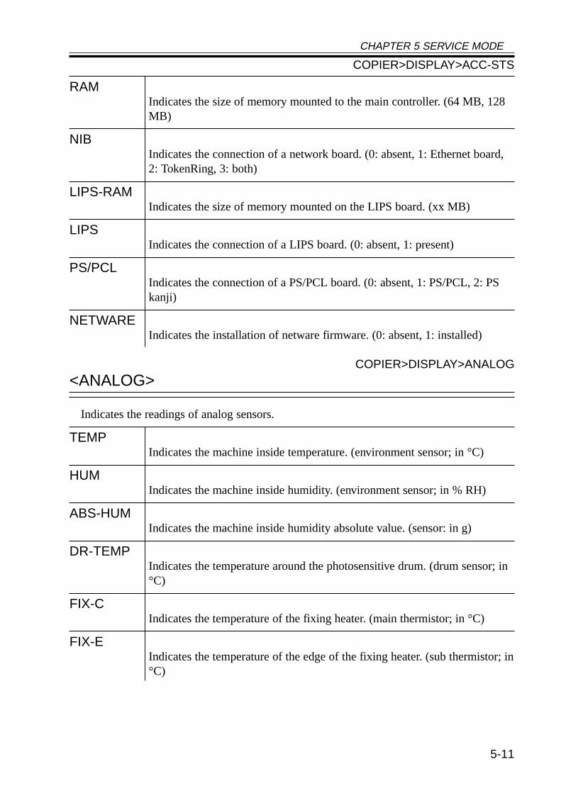
CHAPTER 5 SERVICE MODE
5-11
RAMIndicates the size of memory mounted to the main controller. (64 MB, 128MB)
NIBIndicates the connection of a network board. (0: absent, 1: Ethernet board,2: TokenRing, 3: both)
LIPS-RAMIndicates the size of memory mounted on the LIPS board. (xx MB)
LIPSIndicates the connection of a LIPS board. (0: absent, 1: present)
PS/PCLIndicates the connection of a PS/PCL board. (0: absent, 1: PS/PCL, 2: PSkanji)
NETWAREIndicates the installation of netware firmware. (0: absent, 1: installed)
COPIER>DISPLAY>ANALOG
<ANALOG>
Indicates the readings of analog sensors.
TEMPIndicates the machine inside temperature. (environment sensor; in °C)
HUMIndicates the machine inside humidity. (environment sensor; in % RH)
ABS-HUMIndicates the machine inside humidity absolute value. (sensor: in g)
DR-TEMPIndicates the temperature around the photosensitive drum. (drum sensor; in°C)
FIX-CIndicates the temperature of the fixing heater. (main thermistor; in °C)
FIX-EIndicates the temperature of the edge of the fixing heater. (sub thermistor; in°C)
COPIER>DISPLAY>ACC-STS

CHAPTER 5 SERVICE MODE
5-12
<CST-STS>
Indicates the size of paper in the cassettes and the manual feeder.
WIDTH-MFIndicates the width of paper in terms of paper size (manual feed).
COPIER>DISPLAY>CTS-STS
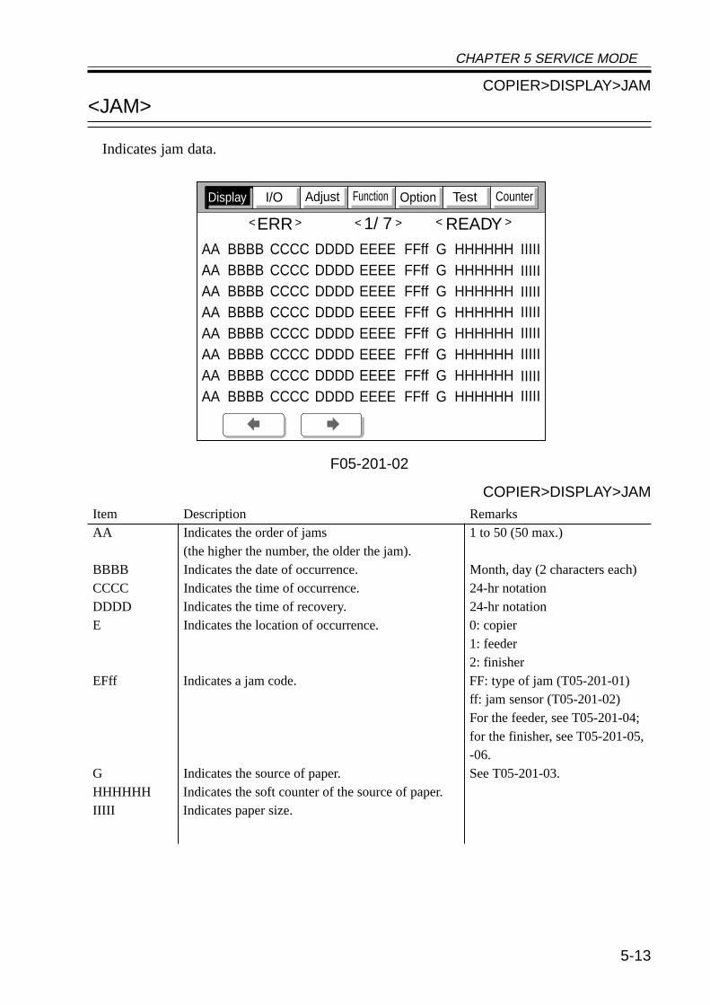
CHAPTER 5 SERVICE MODE
5-13
Item Description RemarksAA Indicates the order of jams 1 to 50 (50 max.)
(the higher the number, the older the jam).BBBB Indicates the date of occurrence. Month, day (2 characters each)CCCC Indicates the time of occurrence. 24-hr notationDDDD Indicates the time of recovery. 24-hr notationE Indicates the location of occurrence. 0: copier
1: feeder2: finisher
EFff Indicates a jam code. FF: type of jam (T05-201-01)ff: jam sensor (T05-201-02)For the feeder, see T05-201-04;for the finisher, see T05-201-05,-06.
G Indicates the source of paper. See T05-201-03.HHHHHH Indicates the soft counter of the source of paper.IIIII Indicates paper size.
COPIER>DISPLAY>JAM
COPIER>DISPLAY>JAM
<JAM>
Indicates jam data.
F05-201-02
CounterTestOptionFunctionAdjustI/ODisplay
ERR 1/ 7 READY
AAAAAAAAAAAAAAAA
BBBBBBBBBBBBBBBBBBBBBBBBBBBBBBBB
CCCCCCCCCCCCCCCCCCCCCCCCCCCCCCCC
DDDDDDDDDDDDDDDDDDDDDDDDDDDDDDDD
EEEEEEEEEEEEEEEEEEEEEEEEEEEEEEEE
HHHHHHHHHHHHHHHHHHHHHHHHHHHHHHHHHHHHHHHHHHHHHHHH
FFffFFffFFffFFffFFffFFffFFffFFff
IIIII
IIIIIIIIII
IIIIIIIIIIIIIIIIIIIIIIIII
GGGGGGGG
< > < > < >
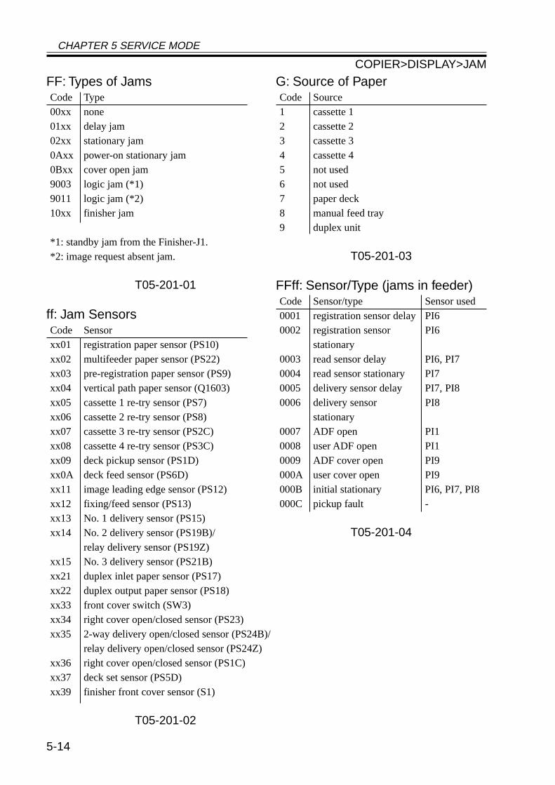
CHAPTER 5 SERVICE MODE
5-14
FF: Types of JamsCode Type00xx none01xx delay jam02xx stationary jam0Axx power-on stationary jam0Bxx cover open jam9003 logic jam (*1)9011 logic jam (*2)10xx finisher jam
*1: standby jam from the Finisher-J1.*2: image request absent jam.
T05-201-01
ff: Jam SensorsCode Sensorxx01 registration paper sensor (PS10)xx02 multifeeder paper sensor (PS22)xx03 pre-registration paper sensor (PS9)xx04 vertical path paper sensor (Q1603)xx05 cassette 1 re-try sensor (PS7)xx06 cassette 2 re-try sensor (PS8)xx07 cassette 3 re-try sensor (PS2C)xx08 cassette 4 re-try sensor (PS3C)xx09 deck pickup sensor (PS1D)xx0A deck feed sensor (PS6D)xx11 image leading edge sensor (PS12)xx12 fixing/feed sensor (PS13)xx13 No. 1 delivery sensor (PS15)xx14 No. 2 delivery sensor (PS19B)/
relay delivery sensor (PS19Z)xx15 No. 3 delivery sensor (PS21B)xx21 duplex inlet paper sensor (PS17)xx22 duplex output paper sensor (PS18)xx33 front cover switch (SW3)xx34 right cover open/closed sensor (PS23)xx35 2-way delivery open/closed sensor (PS24B)/
relay delivery open/closed sensor (PS24Z)xx36 right cover open/closed sensor (PS1C)xx37 deck set sensor (PS5D)xx39 finisher front cover sensor (S1)
T05-201-02
G: Source of PaperCode Source1 cassette 12 cassette 23 cassette 34 cassette 45 not used6 not used7 paper deck8 manual feed tray9 duplex unit
T05-201-03
FFff: Sensor/Type (jams in feeder)Code Sensor/type Sensor used0001 registration sensor delay PI60002 registration sensor PI6
stationary0003 read sensor delay PI6, PI70004 read sensor stationary PI70005 delivery sensor delay PI7, PI80006 delivery sensor PI8
stationary0007 ADF open PI10008 user ADF open PI10009 ADF cover open PI9000A user cover open PI9000B initial stationary PI6, PI7, PI8000C pickup fault -
T05-201-04
COPIER>DISPLAY>JAM
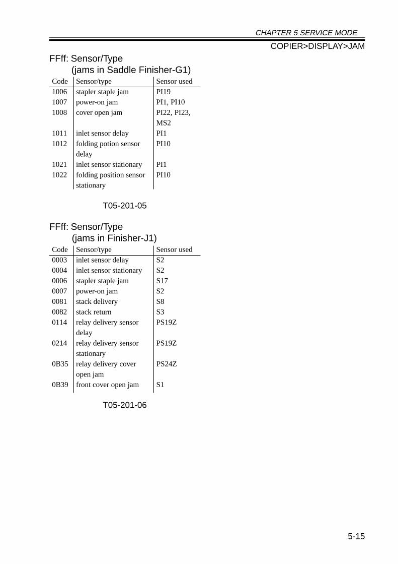
CHAPTER 5 SERVICE MODE
5-15
FFff: Sensor/Type(jams in Saddle Finisher-G1)
Code Sensor/type Sensor used1006 stapler staple jam PI191007 power-on jam PI1, PI101008 cover open jam PI22, PI23,
MS21011 inlet sensor delay PI11012 folding potion sensor PI10
delay1021 inlet sensor stationary PI11022 folding position sensor PI10
stationary
T05-201-05
FFff: Sensor/Type(jams in Finisher-J1)
Code Sensor/type Sensor used0003 inlet sensor delay S20004 inlet sensor stationary S20006 stapler staple jam S170007 power-on jam S20081 stack delivery S80082 stack return S30114 relay delivery sensor PS19Z
delay0214 relay delivery sensor PS19Z
stationary0B35 relay delivery cover PS24Z
open jam0B39 front cover open jam S1
T05-201-06
COPIER>DISPLAY>JAM
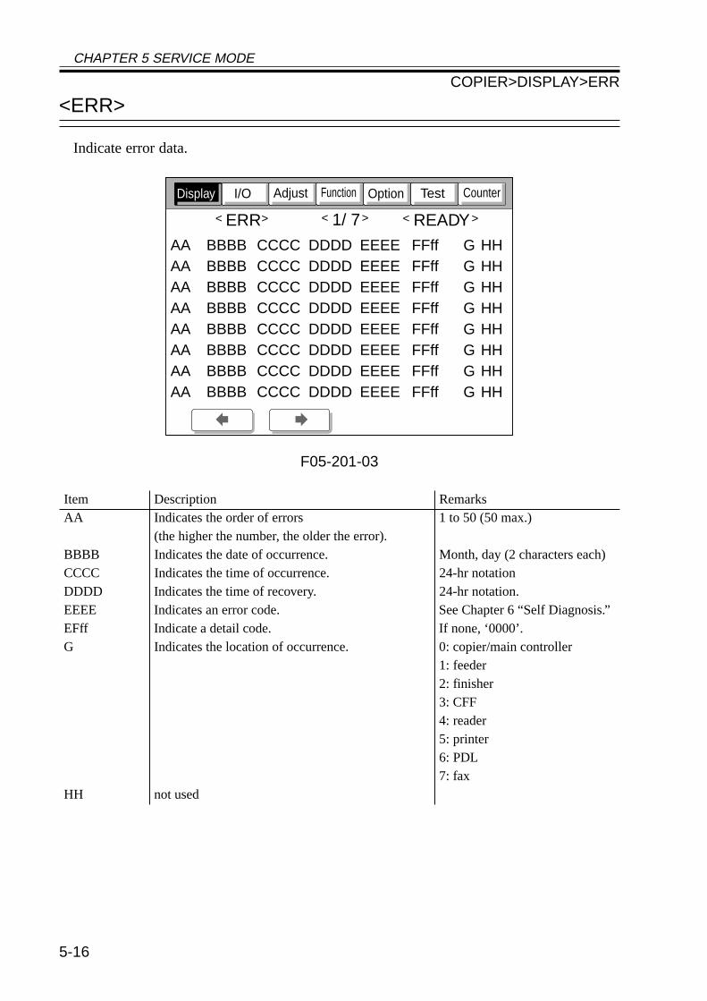
CHAPTER 5 SERVICE MODE
5-16
<ERR>
Indicate error data.
F05-201-03
Item Description RemarksAA Indicates the order of errors 1 to 50 (50 max.)
(the higher the number, the older the error).BBBB Indicates the date of occurrence. Month, day (2 characters each)CCCC Indicates the time of occurrence. 24-hr notationDDDD Indicates the time of recovery. 24-hr notation.EEEE Indicates an error code. See Chapter 6 “Self Diagnosis.”EFff Indicate a detail code. If none, ‘0000’.G Indicates the location of occurrence. 0: copier/main controller
1: feeder2: finisher3: CFF4: reader5: printer6: PDL7: fax
HH not used
CounterTestOptionFunctionAdjustI/ODisplay
ERR 1/ 7 READY
AAAAAAAAAAAAAAAA
BBBBBBBBBBBBBBBBBBBBBBBBBBBBBBBB
CCCCCCCCCCCCCCCCCCCCCCCCCCCCCCCC
DDDDDDDDDDDDDDDDDDDDDDDDDDDDDDDD
EEEEEEEEEEEEEEEEEEEEEEEEEEEEEEEE
FFffFFffFFffFFffFFffFFffFFffFFff
HHHHHHHHHHHHHHHH
GGGGGGGG
< > < > < >
COPIER>DISPLAY>ERR
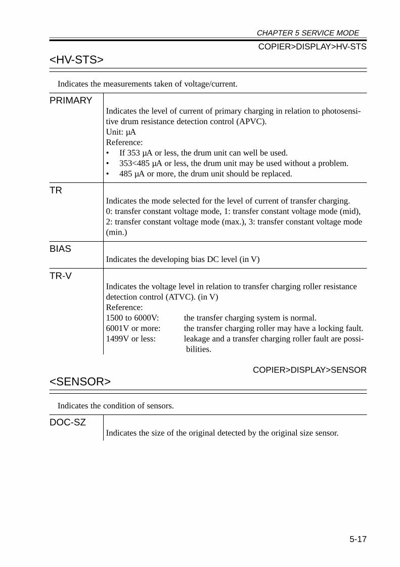
CHAPTER 5 SERVICE MODE
5-17
<HV-STS>
Indicates the measurements taken of voltage/current.
PRIMARYIndicates the level of current of primary charging in relation to photosensi-tive drum resistance detection control (APVC).Unit: µAReference:• If 353 µA or less, the drum unit can well be used.• 353<485 µA or less, the drum unit may be used without a problem.• 485 µA or more, the drum unit should be replaced.
TRIndicates the mode selected for the level of current of transfer charging.0: transfer constant voltage mode, 1: transfer constant voltage mode (mid),2: transfer constant voltage mode (max.), 3: transfer constant voltage mode(min.)
BIASIndicates the developing bias DC level (in V)
TR-VIndicates the voltage level in relation to transfer charging roller resistancedetection control (ATVC). (in V)Reference:1500 to 6000V: the transfer charging system is normal.6001V or more: the transfer charging roller may have a locking fault.1499V or less: leakage and a transfer charging roller fault are possi-
bilities.
COPIER>DISPLAY>SENSOR
<SENSOR>
Indicates the condition of sensors.
DOC-SZIndicates the size of the original detected by the original size sensor.
COPIER>DISPLAY>HV-STS
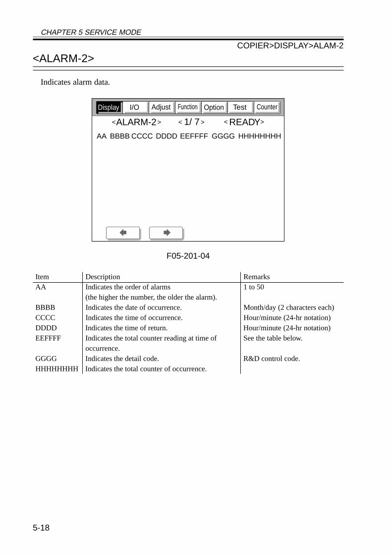
CHAPTER 5 SERVICE MODE
5-18
<ALARM-2>
Indicates alarm data.
F05-201-04
Item Description RemarksAA Indicates the order of alarms 1 to 50
(the higher the number, the older the alarm).BBBB Indicates the date of occurrence. Month/day (2 characters each)CCCC Indicates the time of occurrence. Hour/minute (24-hr notation)DDDD Indicates the time of return. Hour/minute (24-hr notation)EEFFFF Indicates the total counter reading at time of See the table below.
occurrence.GGGG Indicates the detail code. R&D control code.HHHHHHHH Indicates the total counter of occurrence.
CounterTestOptionFunctionAdjustI/ODisplay
ALARM-2 1/ 7 READY< > < > < >
AA BBBB CCCC DDDD EEFFFF GGGG HHHHHHHH
COPIER>DISPLAY>ALAM-2
CHAPTER 5 SERVICE MODE
5-19
EE (location code) EE (location) FFFF (description)02 scanner in reader unit 0002: Indicate of dirt on reading glass in stream
reading mode (small-size)04 pickup/feed system 0008: paper deck lifter fault
0011: cassette 1 re-try alarm0012: cassette 2 re-try alarm0013: cassette 3 re-try alarm0014: cassette 4 re-try alarm0018: paper deck re-try alarm
61 stapler system of 0001: staple absentsorter/finisher
62 saddle stitcher system 0001: stitch staple absent65 puncher system of 0001: punch waste case full
sorter/finisher
FEEDER>DISPLAY
2.2 FEEDER
FEEDSIZEIndicates the size of the original detected by the ADF.
COPIER>DISPLAY>ALAM-2
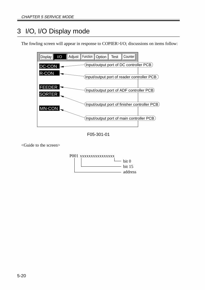
CHAPTER 5 SERVICE MODE
5-20
3 I/O, I/O Display mode
The fowling screen will appear in response to COPIER>I/O; discussions on items follow:
F05-301-01
<Guide to the screen>
P001 xxxxxxxxxxxxxxxxbit 0bit 15address
CounterTestOptionFunctionAdjustDisplay
DC-CON
R-CON
FEEDER
SORTER
MN-CON
I/O
Input/output port of DC controller PCB
Input/output port of ADF controller PCB
Input/output port of finisher controller PCB
Input/output port of main controller PCB
Input/output port of reader controller PCB
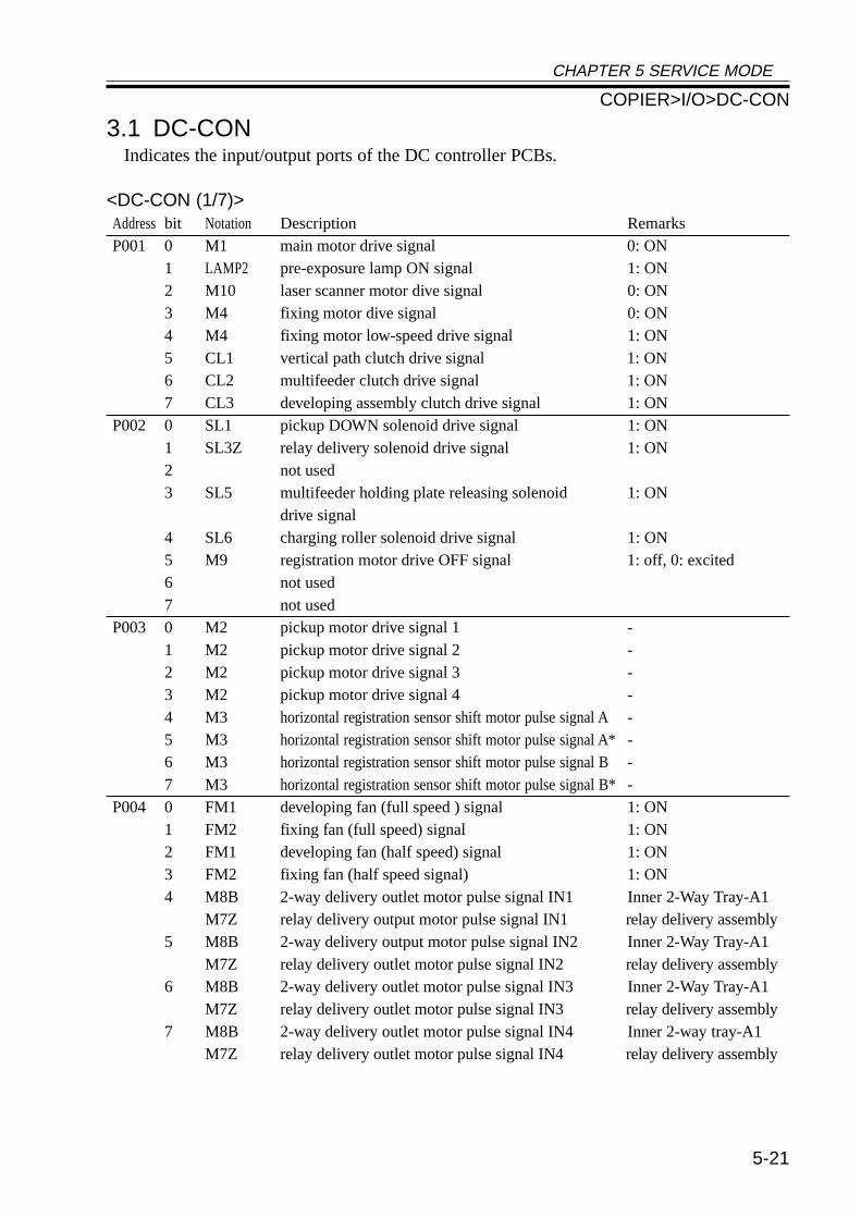
CHAPTER 5 SERVICE MODE
5-21
3.1 DC-CONIndicates the input/output ports of the DC controller PCBs.
<DC-CON (1/7)>Address bit Notation Description RemarksP001 0 M1 main motor drive signal 0: ON
1 LAMP2 pre-exposure lamp ON signal 1: ON2 M10 laser scanner motor dive signal 0: ON3 M4 fixing motor dive signal 0: ON4 M4 fixing motor low-speed drive signal 1: ON5 CL1 vertical path clutch drive signal 1: ON6 CL2 multifeeder clutch drive signal 1: ON7 CL3 developing assembly clutch drive signal 1: ON
P002 0 SL1 pickup DOWN solenoid drive signal 1: ON1 SL3Z relay delivery solenoid drive signal 1: ON2 not used3 SL5 multifeeder holding plate releasing solenoid 1: ON
drive signal4 SL6 charging roller solenoid drive signal 1: ON5 M9 registration motor drive OFF signal 1: off, 0: excited6 not used7 not used
P003 0 M2 pickup motor drive signal 1 -1 M2 pickup motor drive signal 2 -2 M2 pickup motor drive signal 3 -3 M2 pickup motor drive signal 4 -4 M3 horizontal registration sensor shift motor pulse signal A-5 M3 horizontal registration sensor shift motor pulse signal A*-6 M3 horizontal registration sensor shift motor pulse signal B-7 M3 horizontal registration sensor shift motor pulse signal B*-
P004 0 FM1 developing fan (full speed ) signal 1: ON1 FM2 fixing fan (full speed) signal 1: ON2 FM1 developing fan (half speed) signal 1: ON3 FM2 fixing fan (half speed signal) 1: ON4 M8B 2-way delivery outlet motor pulse signal IN1 Inner 2-Way Tray-A1
M7Z relay delivery output motor pulse signal IN1 relay delivery assembly5 M8B 2-way delivery output motor pulse signal IN2 Inner 2-Way Tray-A1
M7Z relay delivery outlet motor pulse signal IN2 relay delivery assembly6 M8B 2-way delivery outlet motor pulse signal IN3 Inner 2-Way Tray-A1
M7Z relay delivery outlet motor pulse signal IN3 relay delivery assembly7 M8B 2-way delivery outlet motor pulse signal IN4 Inner 2-way tray-A1
M7Z relay delivery outlet motor pulse signal IN4 relay delivery assembly
COPIER>I/O>DC-CON
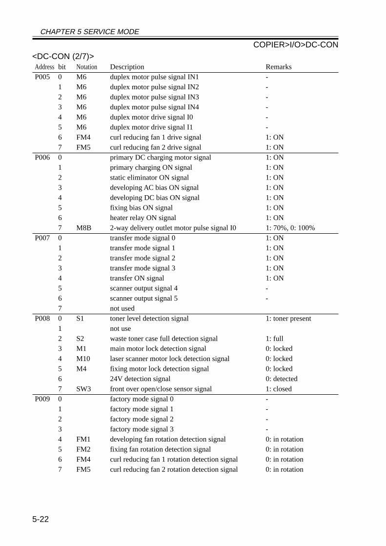
CHAPTER 5 SERVICE MODE
5-22
<DC-CON (2/7)>Address bit Notation Description RemarksP005 0 M6 duplex motor pulse signal IN1 -
1 M6 duplex motor pulse signal IN2 -2 M6 duplex motor pulse signal IN3 -3 M6 duplex motor pulse signal IN4 -4 M6 duplex motor drive signal I0 -5 M6 duplex motor drive signal I1 -6 FM4 curl reducing fan 1 drive signal 1: ON7 FM5 curl reducing fan 2 drive signal 1: ON
P006 0 primary DC charging motor signal 1: ON1 primary charging ON signal 1: ON2 static eliminator ON signal 1: ON3 developing AC bias ON signal 1: ON4 developing DC bias ON signal 1: ON5 fixing bias ON signal 1: ON6 heater relay ON signal 1: ON7 M8B 2-way delivery outlet motor pulse signal I0 1: 70%, 0: 100%
P007 0 transfer mode signal 0 1: ON1 transfer mode signal 1 1: ON2 transfer mode signal 2 1: ON3 transfer mode signal 3 1: ON4 transfer ON signal 1: ON5 scanner output signal 4 -6 scanner output signal 5 -7 not used
P008 0 S1 toner level detection signal 1: toner present1 not use2 S2 waste toner case full detection signal 1: full3 M1 main motor lock detection signal 0: locked4 M10 laser scanner motor lock detection signal 0: locked5 M4 fixing motor lock detection signal 0: locked6 24V detection signal 0: detected7 SW3 front over open/close sensor signal 1: closed
P009 0 factory mode signal 0 -1 factory mode signal 1 -2 factory mode signal 2 -3 factory mode signal 3 -4 FM1 developing fan rotation detection signal 0: in rotation5 FM2 fixing fan rotation detection signal 0: in rotation6 FM4 curl reducing fan 1 rotation detection signal 0: in rotation7 FM5 curl reducing fan 2 rotation detection signal 0: in rotation
COPIER>I/O>DC-CON
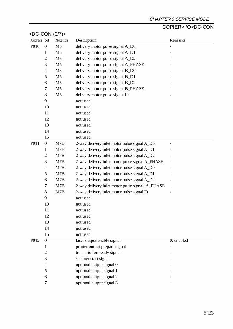
CHAPTER 5 SERVICE MODE
5-23
<DC-CON (3/7)>Address bit Notation Description RemarksP010 0 M5 delivery motor pulse signal A_D0 -
1 M5 delivery motor pulse signal A_D1 -2 M5 delivery motor pulse signal A_D2 -3 M5 delivery motor pulse signal A_PHASE -4 M5 delivery motor pulse signal B_D0 -5 M5 delivery motor pulse signal B_D1 -6 M5 delivery motor pulse signal B_D2 -7 M5 delivery motor pulse signal B_PHASE -8 M5 delivery motor pulse signal I0 -9 not used10 not used11 not used12 not used13 not used14 not used15 not used
P011 0 M7B 2-way delivery inlet motor pulse signal A_D0 -1 M7B 2-way delivery inlet motor pulse signal A_D1 -2 M7B 2-way delivery inlet motor pulse signal A_D2 -3 M7B 2-way delivery inlet motor pulse signal A_PHASE -4 M7B 2-way delivery inlet motor pulse signal A_D0 -5 M7B 2-way delivery inlet motor pulse signal A_D1 -6 M7B 2-way delivery inlet motor pulse signal A_D2 -7 M7B 2-way delivery inlet motor pulse signal lA_PHASE -8 M7B 2-way delivery inlet motor pulse signal I0 -9 not used10 not used11 not used12 not used13 not used14 not used15 not used
P012 0 laser output enable signal 0: enabled1 printer output prepare signal -2 transmission ready signal -3 scanner start signal -4 optional output signal 0 -5 optional output signal 1 -6 optional output signal 2 -7 optional output signal 3 -
COPIER>I/O>DC-CON
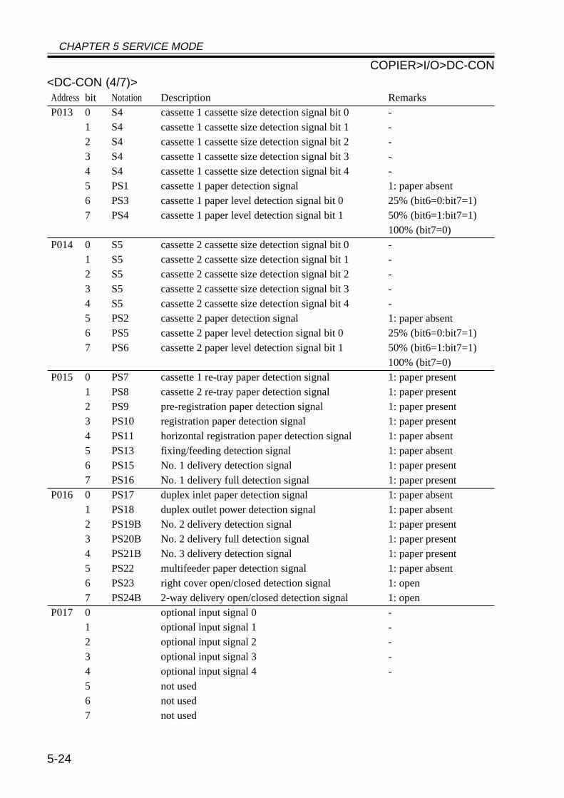
CHAPTER 5 SERVICE MODE
5-24
<DC-CON (4/7)>Address bit Notation Description RemarksP013 0 S4 cassette 1 cassette size detection signal bit 0 -
1 S4 cassette 1 cassette size detection signal bit 1 -2 S4 cassette 1 cassette size detection signal bit 2 -3 S4 cassette 1 cassette size detection signal bit 3 -4 S4 cassette 1 cassette size detection signal bit 4 -5 PS1 cassette 1 paper detection signal 1: paper absent6 PS3 cassette 1 paper level detection signal bit 0 25% (bit6=0:bit7=1)7 PS4 cassette 1 paper level detection signal bit 1 50% (bit6=1:bit7=1)
100% (bit7=0)P014 0 S5 cassette 2 cassette size detection signal bit 0 -
1 S5 cassette 2 cassette size detection signal bit 1 -2 S5 cassette 2 cassette size detection signal bit 2 -3 S5 cassette 2 cassette size detection signal bit 3 -4 S5 cassette 2 cassette size detection signal bit 4 -5 PS2 cassette 2 paper detection signal 1: paper absent6 PS5 cassette 2 paper level detection signal bit 0 25% (bit6=0:bit7=1)7 PS6 cassette 2 paper level detection signal bit 1 50% (bit6=1:bit7=1)
100% (bit7=0)P015 0 PS7 cassette 1 re-tray paper detection signal 1: paper present
1 PS8 cassette 2 re-tray paper detection signal 1: paper present2 PS9 pre-registration paper detection signal 1: paper present3 PS10 registration paper detection signal 1: paper present4 PS11 horizontal registration paper detection signal 1: paper absent5 PS13 fixing/feeding detection signal 1: paper absent6 PS15 No. 1 delivery detection signal 1: paper present7 PS16 No. 1 delivery full detection signal 1: paper present
P016 0 PS17 duplex inlet paper detection signal 1: paper absent1 PS18 duplex outlet power detection signal 1: paper absent2 PS19B No. 2 delivery detection signal 1: paper present3 PS20B No. 2 delivery full detection signal 1: paper present4 PS21B No. 3 delivery detection signal 1: paper present5 PS22 multifeeder paper detection signal 1: paper absent6 PS23 right cover open/closed detection signal 1: open7 PS24B 2-way delivery open/closed detection signal 1: open
P017 0 optional input signal 0 -1 optional input signal 1 -2 optional input signal 2 -3 optional input signal 3 -4 optional input signal 4 -5 not used6 not used7 not used
COPIER>I/O>DC-CON
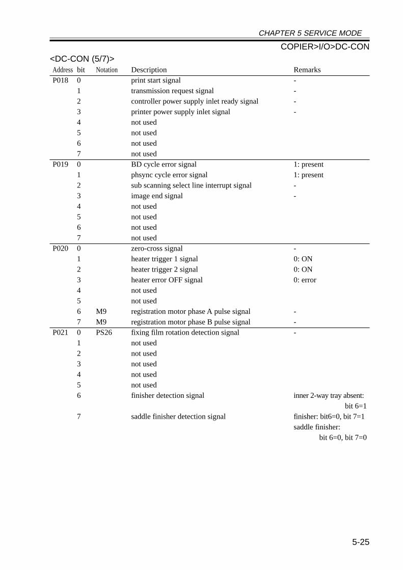
CHAPTER 5 SERVICE MODE
5-25
<DC-CON (5/7)>Address bit Notation Description RemarksP018 0 print start signal -
1 transmission request signal -2 controller power supply inlet ready signal -3 printer power supply inlet signal -4 not used5 not used6 not used7 not used
P019 0 BD cycle error signal 1: present1 phsync cycle error signal 1: present2 sub scanning select line interrupt signal -3 image end signal -4 not used5 not used6 not used7 not used
P020 0 zero-cross signal -1 heater trigger 1 signal 0: ON2 heater trigger 2 signal 0: ON3 heater error OFF signal 0: error4 not used5 not used6 M9 registration motor phase A pulse signal -7 M9 registration motor phase B pulse signal -
P021 0 PS26 fixing film rotation detection signal -1 not used2 not used3 not used4 not used5 not used6 finisher detection signal inner 2-way tray absent:
bit 6=17 saddle finisher detection signal finisher: bit6=0, bit 7=1
saddle finisher:bit 6=0, bit 7=0
COPIER>I/O>DC-CON
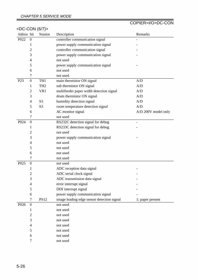
CHAPTER 5 SERVICE MODE
5-26
<DC-CON (6/7)>Address bit Notation Description RemarksP022 0 controller communication signal -
1 power supply communication signal -2 controller communication signal -3 power supply communication signal -4 not used5 power supply communication signal -6 not used7 not used
P23 0 TH1 main thermistor ON signal A/D1 TH2 sub thermistor ON signal A/D2 VR1 multifeeder paper width detection signal A/D3 drum thermistor ON signal A/D4 S3 humidity detection signal A/D5 S3 room temperature detection signal A/D6 AC monitor signal A/D 200V model only7 not used
P024 0 RS232C detection signal for debug -1 RS233C detection signal for debug -2 not used3 power supply communication signal -4 not used5 not used6 not used7 not used
P025 0 not used1 ADC reception data signal -2 ADC serial clock signal -3 ADC transmission data signal -4 error interrupt signal -5 DDI interrupt signal -6 power supply communication signal -7 PS12 image leading edge sensor detection signal 1: paper present
P026 0 not used1 not used2 not used3 not used4 not used5 not used6 not used7 not used
COPIER>I/O>DC-CON
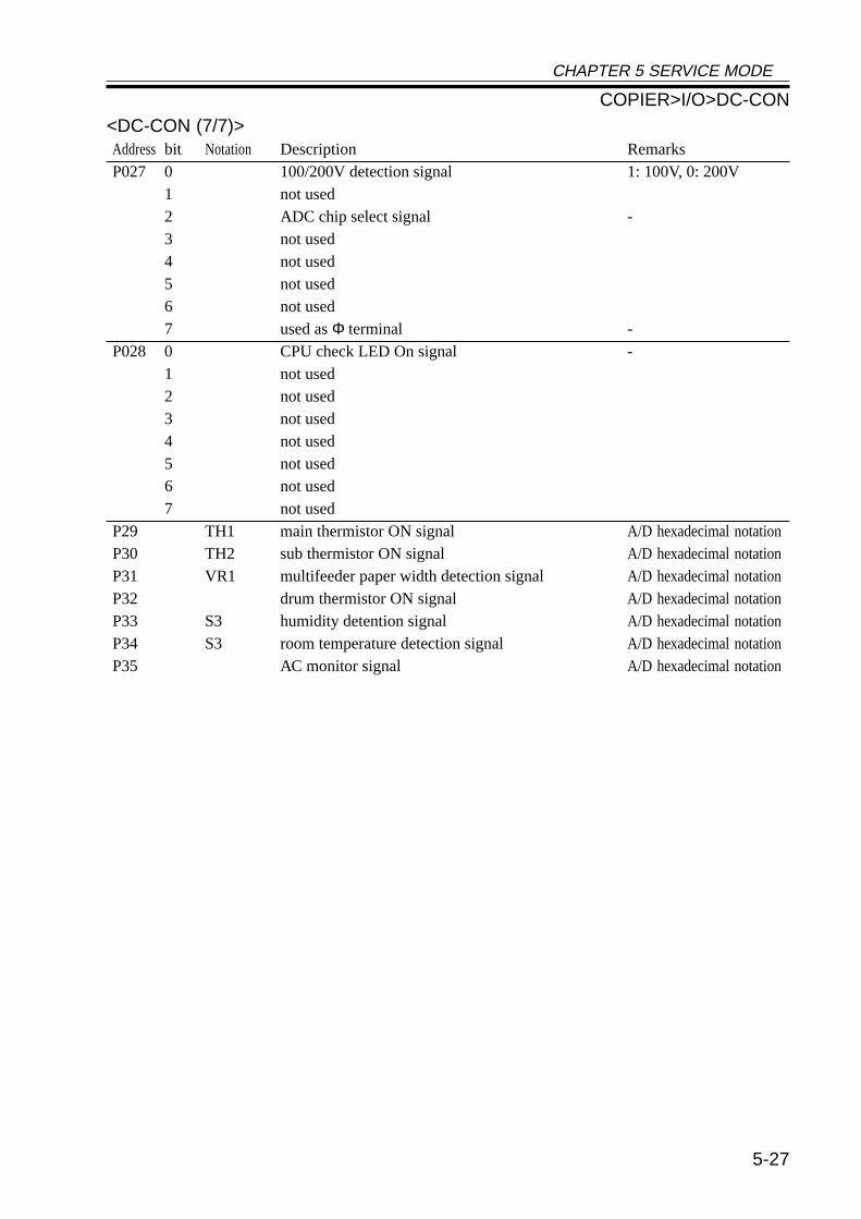
CHAPTER 5 SERVICE MODE
5-27
<DC-CON (7/7)>Address bit Notation Description RemarksP027 0 100/200V detection signal 1: 100V, 0: 200V
1 not used2 ADC chip select signal -3 not used4 not used5 not used6 not used7 used as Φ terminal -
P028 0 CPU check LED On signal -1 not used2 not used3 not used4 not used5 not used6 not used7 not used
P29 TH1 main thermistor ON signal A/D hexadecimal notationP30 TH2 sub thermistor ON signal A/D hexadecimal notationP31 VR1 multifeeder paper width detection signal A/D hexadecimal notationP32 drum thermistor ON signal A/D hexadecimal notationP33 S3 humidity detention signal A/D hexadecimal notationP34 S3 room temperature detection signal A/D hexadecimal notationP35 AC monitor signal A/D hexadecimal notation
COPIER>I/O>DC-CON
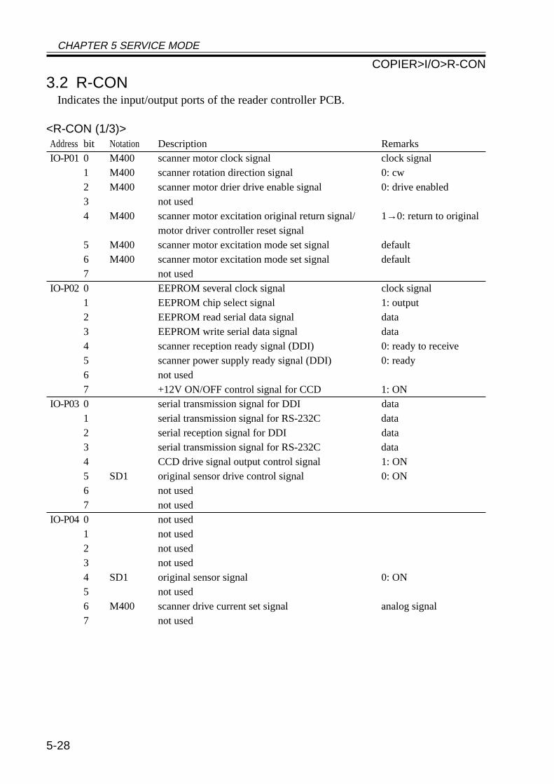
CHAPTER 5 SERVICE MODE
5-28
3.2 R-CONIndicates the input/output ports of the reader controller PCB.
<R-CON (1/3)>Address bit Notation Description RemarksIO-P01 0 M400 scanner motor clock signal clock signal
1 M400 scanner rotation direction signal 0: cw2 M400 scanner motor drier drive enable signal 0: drive enabled3 not used4 M400 scanner motor excitation original return signal/ 1→0: return to original
motor driver controller reset signal5 M400 scanner motor excitation mode set signal default6 M400 scanner motor excitation mode set signal default7 not used
IO-P02 0 EEPROM several clock signal clock signal1 EEPROM chip select signal 1: output2 EEPROM read serial data signal data3 EEPROM write serial data signal data4 scanner reception ready signal (DDI) 0: ready to receive5 scanner power supply ready signal (DDI) 0: ready6 not used7 +12V ON/OFF control signal for CCD 1: ON
IO-P03 0 serial transmission signal for DDI data1 serial transmission signal for RS-232C data2 serial reception signal for DDI data3 serial transmission signal for RS-232C data4 CCD drive signal output control signal 1: ON5 SD1 original sensor drive control signal 0: ON6 not used7 not used
IO-P04 0 not used1 not used2 not used3 not used4 SD1 original sensor signal 0: ON5 not used6 M400 scanner drive current set signal analog signal7 not used
COPIER>I/O>R-CON
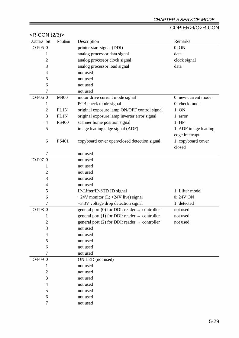
CHAPTER 5 SERVICE MODE
5-29
<R-CON (2/3)>Address bit Notation Description RemarksIO-P05 0 printer start signal (DDI) 0: ON
1 analog processor data signal data2 analog processor clock signal clock signal3 analog processor load signal data4 not used5 not used6 not used7 not used
IO-P06 0 M400 motor drive current mode signal 0: new current mode1 PCB check mode signal 0: check mode2 FL1N original exposure lamp ON/OFF control signal 1: ON3 FL1N original exposure lamp inverter error signal 1: error4 PS400 scanner home position signal 1: HP5 image leading edge signal (ADF) 1: ADF image leading
edge interrupt6 PS401 copyboard cover open/closed detection signal 1: copyboard cover
closed7 not used
IO-P07 0 not used1 not used2 not used3 not used4 not used5 IP-Lifter/IP-STD ID signal 1: Lifter model6 +24V monitor (L: +24V live) signal 0: 24V ON7 +3.3V voltage drop detection signal 1: detected
IO-P08 0 general port (0) for DDI: reader → controller not used1 general port (1) for DDI: reader → controller not used2 general port (2) for DDI: reader → controller not used3 not used4 not used5 not used6 not used7 not used
IO-P09 0 ON LED (not used)1 not used2 not used3 not used4 not used5 not used6 not used7 not used
COPIER>I/O>R-CON
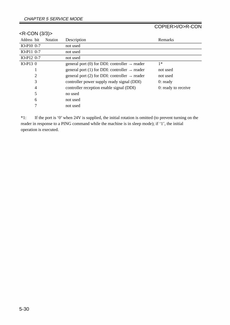
CHAPTER 5 SERVICE MODE
5-30
<R-CON (3/3)>Address bit Notation Description RemarksIO-P10 0-7 not usedIO-P11 0-7 not usedIO-P12 0-7 not usedIO-P13 0 general port (0) for DDI: controller → reader 1*
1 general port (1) for DDI: controller → reader not used2 general port (2) for DDI: controller → reader not used3 controller power supply ready signal (DDI) 0: ready4 controller reception enable signal (DDI) 0: ready to receive5 no used6 not used7 not used
*1: If the port is ‘0’ when 24V is supplied, the initial rotation is omitted (to prevent turning on thereader in response to a PING command while the machine is in sleep mode); if ‘1’, the initialoperation is executed.
COPIER>I/O>R-CON
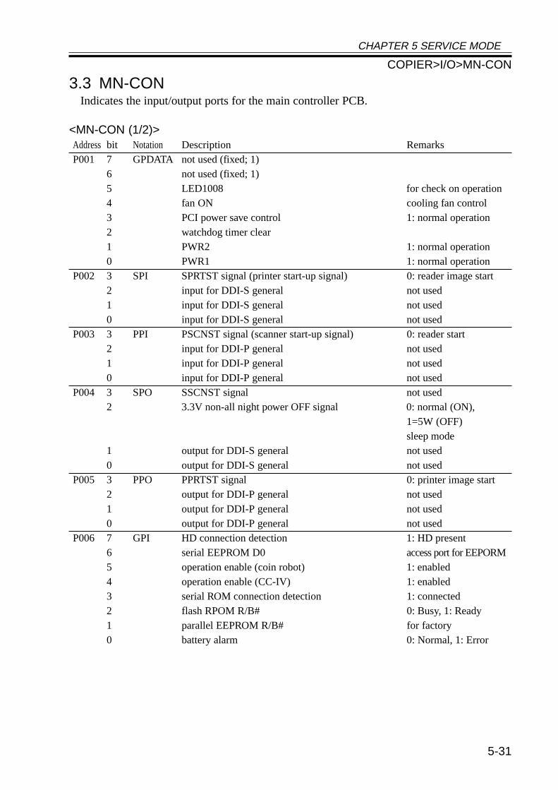
CHAPTER 5 SERVICE MODE
5-31
3.3 MN-CONIndicates the input/output ports for the main controller PCB.
<MN-CON (1/2)>Address bit Notation Description RemarksP001 7 GPDATA not used (fixed; 1)
6 not used (fixed; 1)5 LED1008 for check on operation4 fan ON cooling fan control3 PCI power save control 1: normal operation2 watchdog timer clear1 PWR2 1: normal operation0 PWR1 1: normal operation
P002 3 SPI SPRTST signal (printer start-up signal) 0: reader image start2 input for DDI-S general not used1 input for DDI-S general not used0 input for DDI-S general not used
P003 3 PPI PSCNST signal (scanner start-up signal) 0: reader start2 input for DDI-P general not used1 input for DDI-P general not used0 input for DDI-P general not used
P004 3 SPO SSCNST signal not used2 3.3V non-all night power OFF signal 0: normal (ON),
1=5W (OFF)sleep mode
1 output for DDI-S general not used0 output for DDI-S general not used
P005 3 PPO PPRTST signal 0: printer image start2 output for DDI-P general not used1 output for DDI-P general not used0 output for DDI-P general not used
P006 7 GPI HD connection detection 1: HD present6 serial EEPROM D0 access port for EEPORM5 operation enable (coin robot) 1: enabled4 operation enable (CC-IV) 1: enabled3 serial ROM connection detection 1: connected2 flash RPOM R/B# 0: Busy, 1: Ready1 parallel EEPROM R/B# for factory0 battery alarm 0: Normal, 1: Error
COPIER>I/O>MN-CON
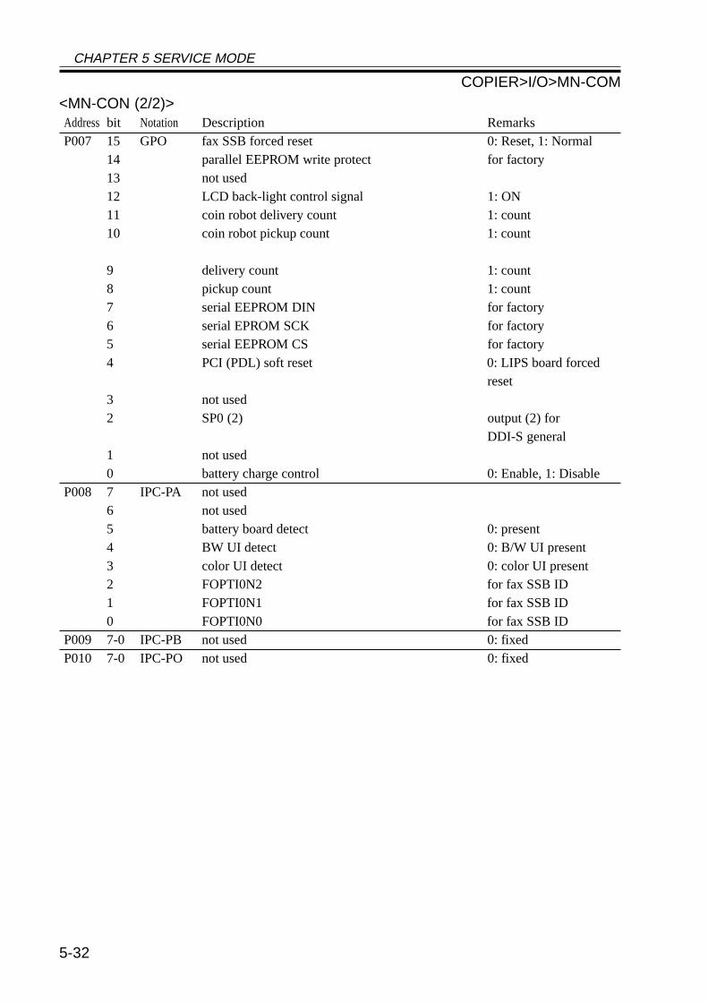
CHAPTER 5 SERVICE MODE
5-32
<MN-CON (2/2)>Address bit Notation Description RemarksP007 15 GPO fax SSB forced reset 0: Reset, 1: Normal
14 parallel EEPROM write protect for factory13 not used12 LCD back-light control signal 1: ON11 coin robot delivery count 1: count10 coin robot pickup count 1: count
9 delivery count 1: count8 pickup count 1: count7 serial EEPROM DIN for factory6 serial EPROM SCK for factory5 serial EEPROM CS for factory4 PCI (PDL) soft reset 0: LIPS board forced
reset3 not used2 SP0 (2) output (2) for
DDI-S general1 not used0 battery charge control 0: Enable, 1: Disable
P008 7 IPC-PA not used6 not used5 battery board detect 0: present4 BW UI detect 0: B/W UI present3 color UI detect 0: color UI present2 FOPTI0N2 for fax SSB ID1 FOPTI0N1 for fax SSB ID0 FOPTI0N0 for fax SSB ID
P009 7-0 IPC-PB not used 0: fixedP010 7-0 IPC-PO not used 0: fixed
COPIER>I/O>MN-COM
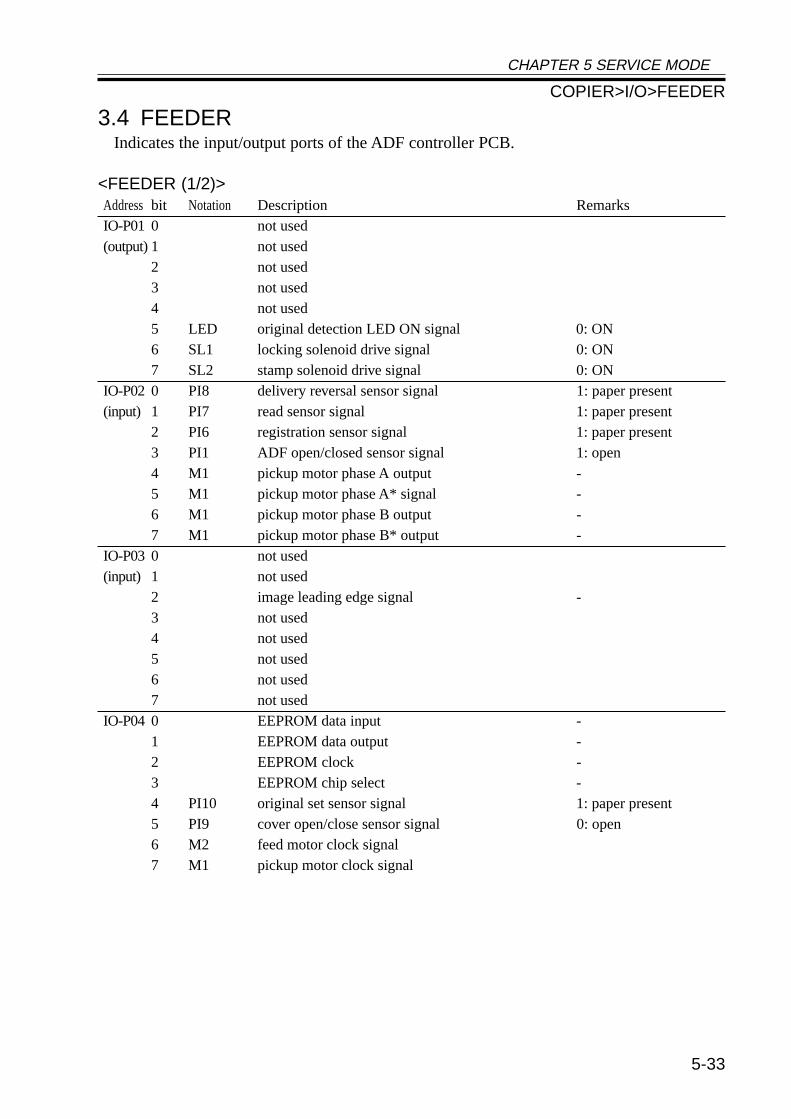
CHAPTER 5 SERVICE MODE
5-33
3.4 FEEDERIndicates the input/output ports of the ADF controller PCB.
<FEEDER (1/2)>Address bit Notation Description RemarksIO-P01 0 not used(output) 1 not used
2 not used3 not used4 not used5 LED original detection LED ON signal 0: ON6 SL1 locking solenoid drive signal 0: ON7 SL2 stamp solenoid drive signal 0: ON
IO-P02 0 PI8 delivery reversal sensor signal 1: paper present(input) 1 PI7 read sensor signal 1: paper present
2 PI6 registration sensor signal 1: paper present3 PI1 ADF open/closed sensor signal 1: open4 M1 pickup motor phase A output -5 M1 pickup motor phase A* signal -6 M1 pickup motor phase B output -7 M1 pickup motor phase B* output -
IO-P03 0 not used(input) 1 not used
2 image leading edge signal -3 not used4 not used5 not used6 not used7 not used
IO-P04 0 EEPROM data input -1 EEPROM data output -2 EEPROM clock -3 EEPROM chip select -4 PI10 original set sensor signal 1: paper present5 PI9 cover open/close sensor signal 0: open6 M2 feed motor clock signal7 M1 pickup motor clock signal
COPIER>I/O>FEEDER
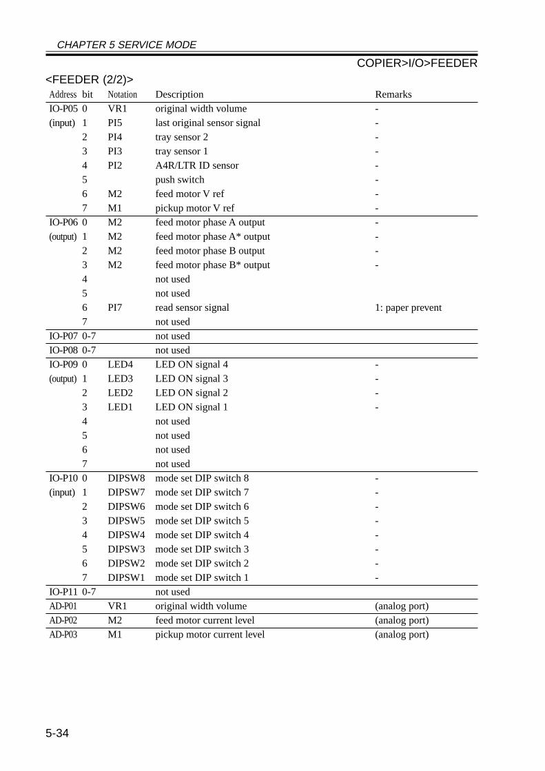
CHAPTER 5 SERVICE MODE
5-34
<FEEDER (2/2)>Address bit Notation Description RemarksIO-P05 0 VR1 original width volume -(input) 1 PI5 last original sensor signal -
2 PI4 tray sensor 2 -3 PI3 tray sensor 1 -4 PI2 A4R/LTR ID sensor -5 push switch -6 M2 feed motor V ref -7 M1 pickup motor V ref -
IO-P06 0 M2 feed motor phase A output -(output) 1 M2 feed motor phase A* output -
2 M2 feed motor phase B output -3 M2 feed motor phase B* output -4 not used5 not used6 PI7 read sensor signal 1: paper prevent7 not used
IO-P07 0-7 not usedIO-P08 0-7 not usedIO-P09 0 LED4 LED ON signal 4 -(output) 1 LED3 LED ON signal 3 -
2 LED2 LED ON signal 2 -3 LED1 LED ON signal 1 -4 not used5 not used6 not used7 not used
IO-P10 0 DIPSW8 mode set DIP switch 8 -(input) 1 DIPSW7 mode set DIP switch 7 -
2 DIPSW6 mode set DIP switch 6 -3 DIPSW5 mode set DIP switch 5 -4 DIPSW4 mode set DIP switch 4 -5 DIPSW3 mode set DIP switch 3 -6 DIPSW2 mode set DIP switch 2 -7 DIPSW1 mode set DIP switch 1 -
IO-P11 0-7 not usedAD-P01 VR1 original width volume (analog port)AD-P02 M2 feed motor current level (analog port)AD-P03 M1 pickup motor current level (analog port)
COPIER>I/O>FEEDER
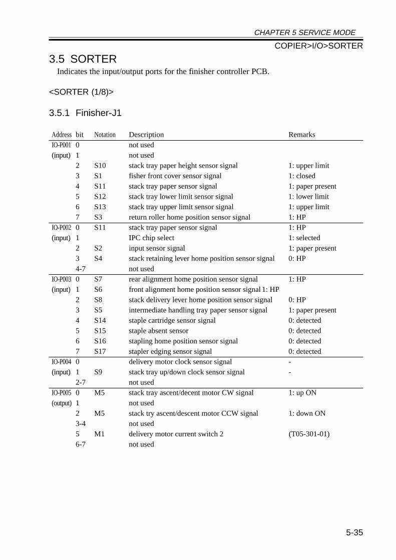
CHAPTER 5 SERVICE MODE
5-35
3.5 SORTERIndicates the input/output ports for the finisher controller PCB.
<SORTER (1/8)>
3.5.1 Finisher-J1
Address bit Notation Description RemarksIO-P001 0 not used(input) 1 not used
2 S10 stack tray paper height sensor signal 1: upper limit3 S1 fisher front cover sensor signal 1: closed4 S11 stack tray paper sensor signal 1: paper present5 S12 stack tray lower limit sensor signal 1: lower limit6 S13 stack tray upper limit sensor signal 1: upper limit7 S3 return roller home position sensor signal 1: HP
IO-P002 0 S11 stack tray paper sensor signal 1: HP(input) 1 IPC chip select 1: selected
2 S2 input sensor signal 1: paper present3 S4 stack retaining lever home position sensor signal 0: HP4-7 not used
IO-P003 0 S7 rear alignment home position sensor signal 1: HP(input) 1 S6 front alignment home position sensor signal 1: HP
2 S8 stack delivery lever home position sensor signal 0: HP3 S5 intermediate handling tray paper sensor signal 1: paper present4 S14 staple cartridge sensor signal 0: detected5 S15 staple absent sensor 0: detected6 S16 stapling home position sensor signal 0: detected7 S17 stapler edging sensor signal 0: detected
IO-P004 0 delivery motor clock sensor signal -(input) 1 S9 stack tray up/down clock sensor signal -
2-7 not usedIO-P005 0 M5 stack tray ascent/decent motor CW signal 1: up ON(output) 1 not used
2 M5 stack try ascent/descent motor CCW signal 1: down ON3-4 not used5 M1 delivery motor current switch 2 (T05-301-01)6-7 not used
COPIER>I/O>SORTER
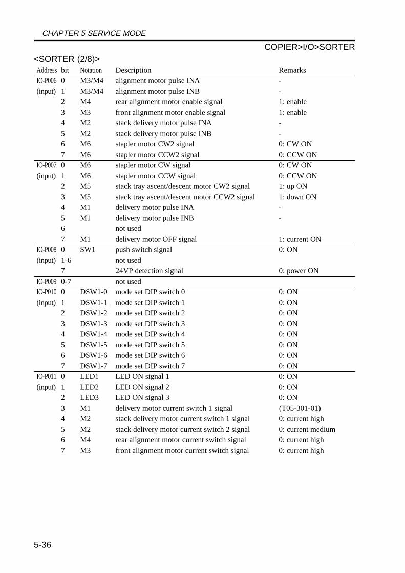
CHAPTER 5 SERVICE MODE
5-36
<SORTER (2/8)>Address bit Notation Description RemarksIO-P006 0 M3/M4 alignment motor pulse INA -(input) 1 M3/M4 alignment motor pulse INB -
2 M4 rear alignment motor enable signal 1: enable3 M3 front alignment motor enable signal 1: enable4 M2 stack delivery motor pulse INA -5 M2 stack delivery motor pulse INB -6 M6 stapler motor CW2 signal 0: CW ON7 M6 stapler motor CCW2 signal 0: CCW ON
IO-P007 0 M6 stapler motor CW signal 0: CW ON(input) 1 M6 stapler motor CCW signal 0: CCW ON
2 M5 stack tray ascent/descent motor CW2 signal 1: up ON3 M5 stack tray ascent/descent motor CCW2 signal 1: down ON4 M1 delivery motor pulse INA -5 M1 delivery motor pulse INB -6 not used7 M1 delivery motor OFF signal 1: current ON
IO-P008 0 SW1 push switch signal 0: ON(input) 1-6 not used
7 24VP detection signal 0: power ONIO-P009 0-7 not usedIO-P010 0 DSW1-0 mode set DIP switch 0 0: ON(input) 1 DSW1-1 mode set DIP switch 1 0: ON
2 DSW1-2 mode set DIP switch 2 0: ON3 DSW1-3 mode set DIP switch 3 0: ON4 DSW1-4 mode set DIP switch 4 0: ON5 DSW1-5 mode set DIP switch 5 0: ON6 DSW1-6 mode set DIP switch 6 0: ON7 DSW1-7 mode set DIP switch 7 0: ON
IO-P011 0 LED1 LED ON signal 1 0: ON(input) 1 LED2 LED ON signal 2 0: ON
2 LED3 LED ON signal 3 0: ON3 M1 delivery motor current switch 1 signal (T05-301-01)4 M2 stack delivery motor current switch 1 signal 0: current high5 M2 stack delivery motor current switch 2 signal 0: current medium6 M4 rear alignment motor current switch signal 0: current high7 M3 front alignment motor current switch signal 0: current high
COPIER>I/O>SORTER
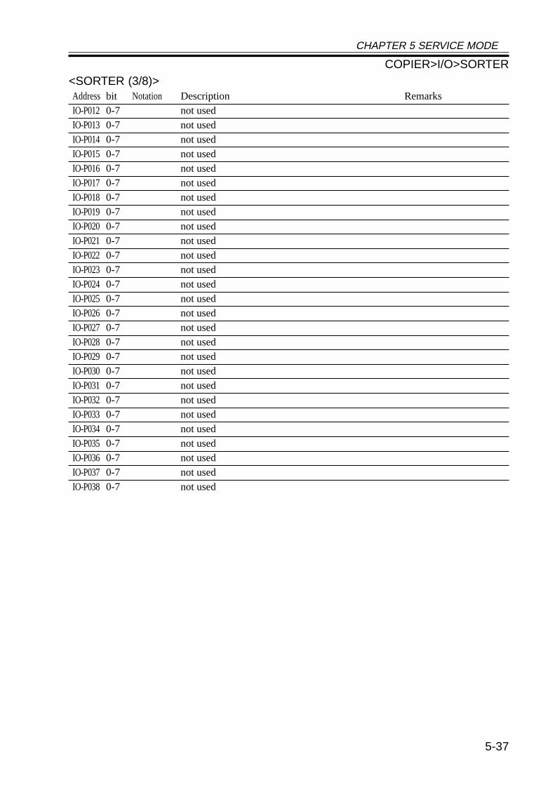
CHAPTER 5 SERVICE MODE
5-37
<SORTER (3/8)>Address bit Notation Description RemarksIO-P012 0-7 not usedIO-P013 0-7 not usedIO-P014 0-7 not usedIO-P015 0-7 not usedIO-P016 0-7 not usedIO-P017 0-7 not usedIO-P018 0-7 not usedIO-P019 0-7 not usedIO-P020 0-7 not usedIO-P021 0-7 not usedIO-P022 0-7 not usedIO-P023 0-7 not usedIO-P024 0-7 not usedIO-P025 0-7 not usedIO-P026 0-7 not usedIO-P027 0-7 not usedIO-P028 0-7 not usedIO-P029 0-7 not usedIO-P030 0-7 not usedIO-P031 0-7 not usedIO-P032 0-7 not usedIO-P033 0-7 not usedIO-P034 0-7 not usedIO-P035 0-7 not usedIO-P036 0-7 not usedIO-P037 0-7 not usedIO-P038 0-7 not used
COPIER>I/O>SORTER
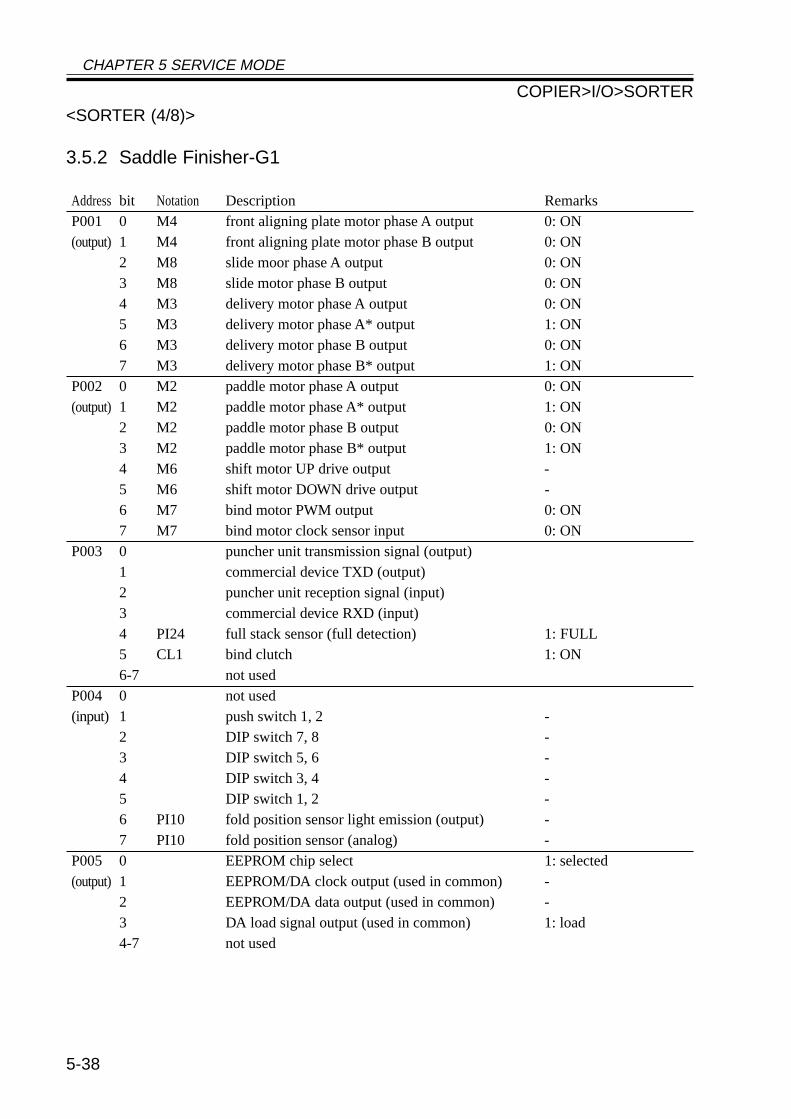
CHAPTER 5 SERVICE MODE
5-38
<SORTER (4/8)>
3.5.2 Saddle Finisher-G1
Address bit Notation Description RemarksP001 0 M4 front aligning plate motor phase A output 0: ON(output) 1 M4 front aligning plate motor phase B output 0: ON
2 M8 slide moor phase A output 0: ON3 M8 slide motor phase B output 0: ON4 M3 delivery motor phase A output 0: ON5 M3 delivery motor phase A* output 1: ON6 M3 delivery motor phase B output 0: ON7 M3 delivery motor phase B* output 1: ON
P002 0 M2 paddle motor phase A output 0: ON(output) 1 M2 paddle motor phase A* output 1: ON
2 M2 paddle motor phase B output 0: ON3 M2 paddle motor phase B* output 1: ON4 M6 shift motor UP drive output -5 M6 shift motor DOWN drive output -6 M7 bind motor PWM output 0: ON7 M7 bind motor clock sensor input 0: ON
P003 0 puncher unit transmission signal (output)1 commercial device TXD (output)2 puncher unit reception signal (input)3 commercial device RXD (input)4 PI24 full stack sensor (full detection) 1: FULL5 CL1 bind clutch 1: ON6-7 not used
P004 0 not used(input) 1 push switch 1, 2 -
2 DIP switch 7, 8 -3 DIP switch 5, 6 -4 DIP switch 3, 4 -5 DIP switch 1, 2 -6 PI10 fold position sensor light emission (output) -7 PI10 fold position sensor (analog) -
P005 0 EEPROM chip select 1: selected(output) 1 EEPROM/DA clock output (used in common) -
2 EEPROM/DA data output (used in common) -3 DA load signal output (used in common) 1: load4-7 not used
COPIER>I/O>SORTER
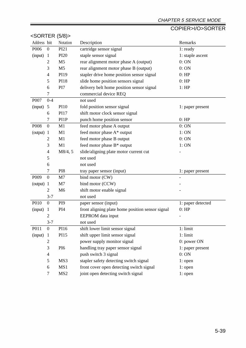
CHAPTER 5 SERVICE MODE
5-39
<SORTER (5/8)>Address bit Notation Description RemarksP006 0 PI21 cartridge sensor signal 1: ready(input) 1 PI20 staple sensor signal 1: staple ascent
2 M5 rear alignment motor phase A (output) 0: ON3 M5 rear alignment motor phase B (output) 0: ON4 PI19 stapler drive home position sensor signal 0: HP5 PI18 slide home position sensors signal 0: HP6 PI7 delivery belt home position sensor signal 1: HP7 commercial device REQ
P007 0-4 not used(input) 5 PI10 fold position sensor signal 1: paper present
6 PI17 shift motor clock sensor signal7 PI1P punch home position sensor 0: HP
P008 0 M1 feed motor phase A output 0: ON(output) 1 M1 feed motor phase A* output 1: ON
2 M1 feed motor phase B output 0: ON3 M1 feed motor phase B* output 1: ON4 M8/4, 5 slide/aligning plate motor current cut -5 not used6 not used7 PI8 tray paper sensor (input) 1: paper present
P009 0 M7 bind motor (CW) -(output) 1 M7 bind motor (CCW) -
2 M6 shift motor enable signal -3-7 not used
P010 0 PI9 paper sensor (input) 1: paper detected(input) 1 PI4 front aligning plate home position sensor signal 0: HP
2 EEPROM data input -3-7 not used
P011 0 PI16 shift lower limit sensor signal 1: limit(input) 1 PI15 shift upper limit sensor signal 1: limit
2 power supply monitor signal 0: power ON3 PI6 handling tray paper sensor signal 1: paper present4 push switch 3 signal 0: ON5 MS3 stapler safety detecting switch signal 1: open6 MS1 front cover open detecting switch signal 1: open7 MS2 joint open detecting switch signal 1: open
COPIER>I/O>SORTER
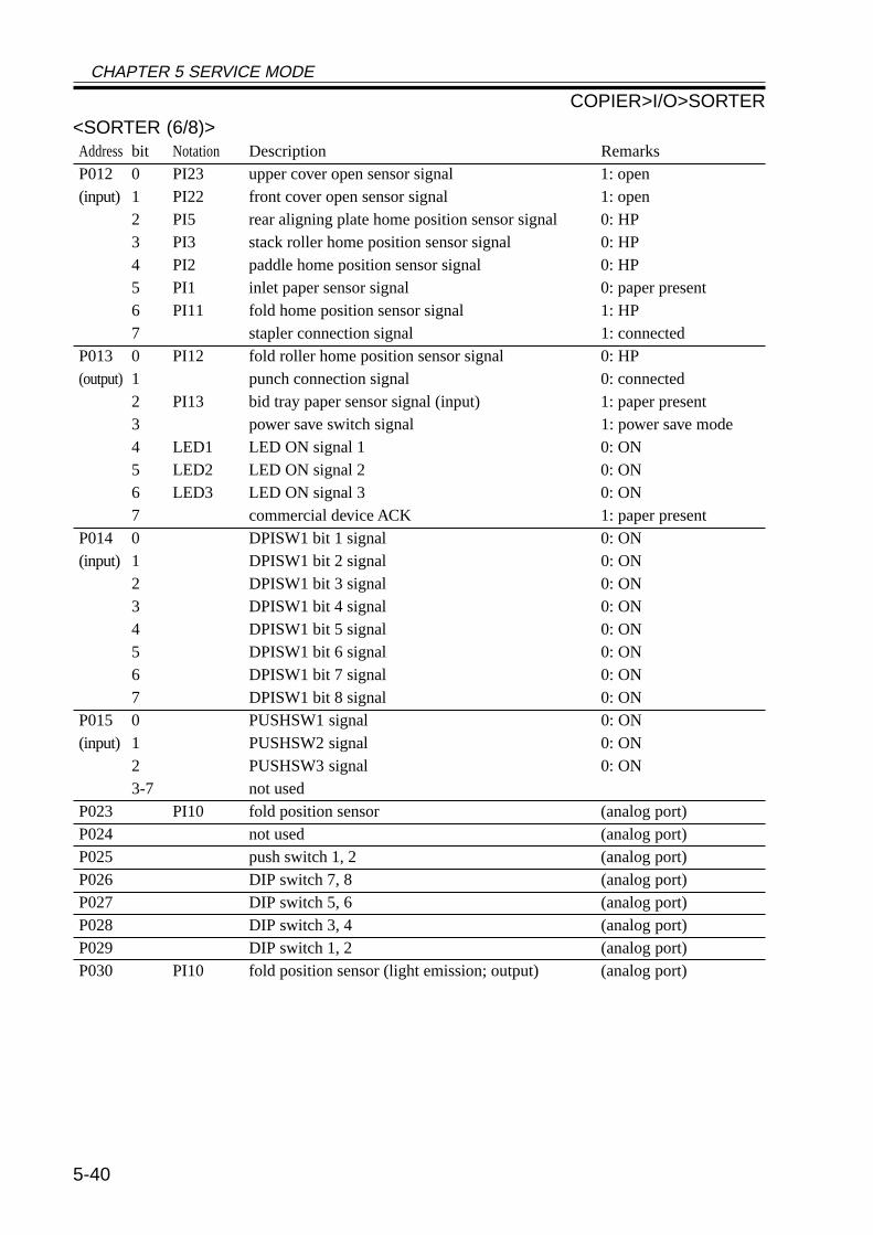
CHAPTER 5 SERVICE MODE
5-40
<SORTER (6/8)>Address bit Notation Description RemarksP012 0 PI23 upper cover open sensor signal 1: open(input) 1 PI22 front cover open sensor signal 1: open
2 PI5 rear aligning plate home position sensor signal 0: HP3 PI3 stack roller home position sensor signal 0: HP4 PI2 paddle home position sensor signal 0: HP5 PI1 inlet paper sensor signal 0: paper present6 PI11 fold home position sensor signal 1: HP7 stapler connection signal 1: connected
P013 0 PI12 fold roller home position sensor signal 0: HP(output) 1 punch connection signal 0: connected
2 PI13 bid tray paper sensor signal (input) 1: paper present3 power save switch signal 1: power save mode4 LED1 LED ON signal 1 0: ON5 LED2 LED ON signal 2 0: ON6 LED3 LED ON signal 3 0: ON7 commercial device ACK 1: paper present
P014 0 DPISW1 bit 1 signal 0: ON(input) 1 DPISW1 bit 2 signal 0: ON
2 DPISW1 bit 3 signal 0: ON3 DPISW1 bit 4 signal 0: ON4 DPISW1 bit 5 signal 0: ON5 DPISW1 bit 6 signal 0: ON6 DPISW1 bit 7 signal 0: ON7 DPISW1 bit 8 signal 0: ON
P015 0 PUSHSW1 signal 0: ON(input) 1 PUSHSW2 signal 0: ON
2 PUSHSW3 signal 0: ON3-7 not used
P023 PI10 fold position sensor (analog port)P024 not used (analog port)P025 push switch 1, 2 (analog port)P026 DIP switch 7, 8 (analog port)P027 DIP switch 5, 6 (analog port)P028 DIP switch 3, 4 (analog port)P029 DIP switch 1, 2 (analog port)P030 PI10 fold position sensor (light emission; output) (analog port)
COPIER>I/O>SORTER
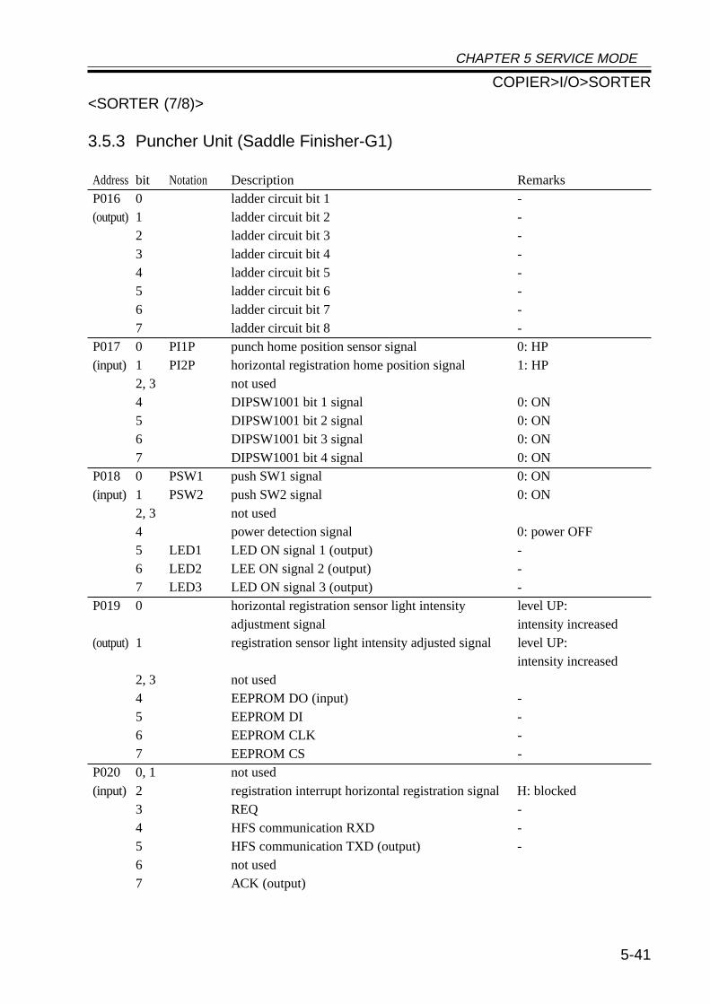
CHAPTER 5 SERVICE MODE
5-41
<SORTER (7/8)>
3.5.3 Puncher Unit (Saddle Finisher-G1)
Address bit Notation Description RemarksP016 0 ladder circuit bit 1 -(output) 1 ladder circuit bit 2 -
2 ladder circuit bit 3 -3 ladder circuit bit 4 -4 ladder circuit bit 5 -5 ladder circuit bit 6 -6 ladder circuit bit 7 -7 ladder circuit bit 8 -
P017 0 PI1P punch home position sensor signal 0: HP(input) 1 PI2P horizontal registration home position signal 1: HP
2, 3 not used4 DIPSW1001 bit 1 signal 0: ON5 DIPSW1001 bit 2 signal 0: ON6 DIPSW1001 bit 3 signal 0: ON7 DIPSW1001 bit 4 signal 0: ON
P018 0 PSW1 push SW1 signal 0: ON(input) 1 PSW2 push SW2 signal 0: ON
2, 3 not used4 power detection signal 0: power OFF5 LED1 LED ON signal 1 (output) -6 LED2 LEE ON signal 2 (output) -7 LED3 LED ON signal 3 (output) -
P019 0 horizontal registration sensor light intensity level UP:adjustment signal intensity increased
(output) 1 registration sensor light intensity adjusted signal level UP:intensity increased
2, 3 not used4 EEPROM DO (input) -5 EEPROM DI -6 EEPROM CLK -7 EEPROM CS -
P020 0, 1 not used(input) 2 registration interrupt horizontal registration signal H: blocked
3 REQ -4 HFS communication RXD -5 HFS communication TXD (output) -6 not used7 ACK (output)
COPIER>I/O>SORTER
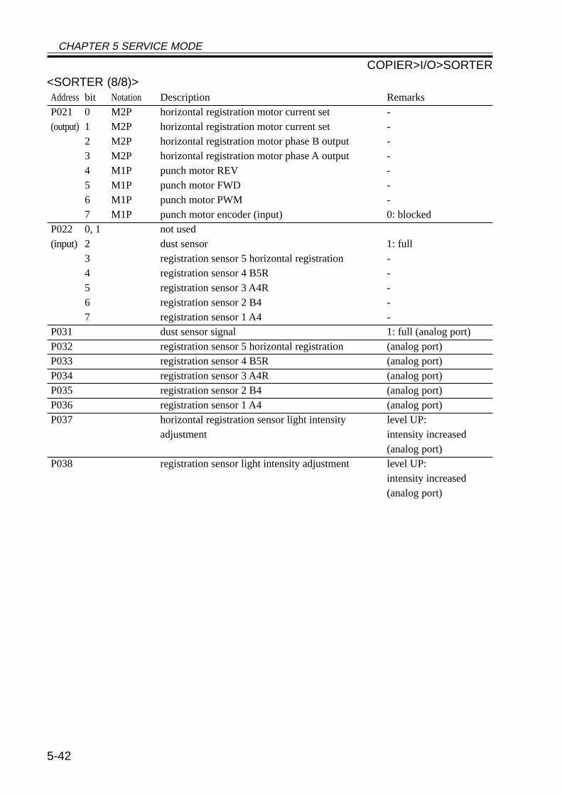
CHAPTER 5 SERVICE MODE
5-42
<SORTER (8/8)>Address bit Notation Description RemarksP021 0 M2P horizontal registration motor current set -(output) 1 M2P horizontal registration motor current set -
2 M2P horizontal registration motor phase B output -3 M2P horizontal registration motor phase A output -4 M1P punch motor REV -5 M1P punch motor FWD -6 M1P punch motor PWM -7 M1P punch motor encoder (input) 0: blocked
P022 0, 1 not used(input) 2 dust sensor 1: full
3 registration sensor 5 horizontal registration -4 registration sensor 4 B5R -5 registration sensor 3 A4R -6 registration sensor 2 B4 -7 registration sensor 1 A4 -
P031 dust sensor signal 1: full (analog port)P032 registration sensor 5 horizontal registration (analog port)P033 registration sensor 4 B5R (analog port)P034 registration sensor 3 A4R (analog port)P035 registration sensor 2 B4 (analog port)P036 registration sensor 1 A4 (analog port)P037 horizontal registration sensor light intensity level UP:
adjustment intensity increased(analog port)
P038 registration sensor light intensity adjustment level UP:intensity increased(analog port)
COPIER>I/O>SORTER
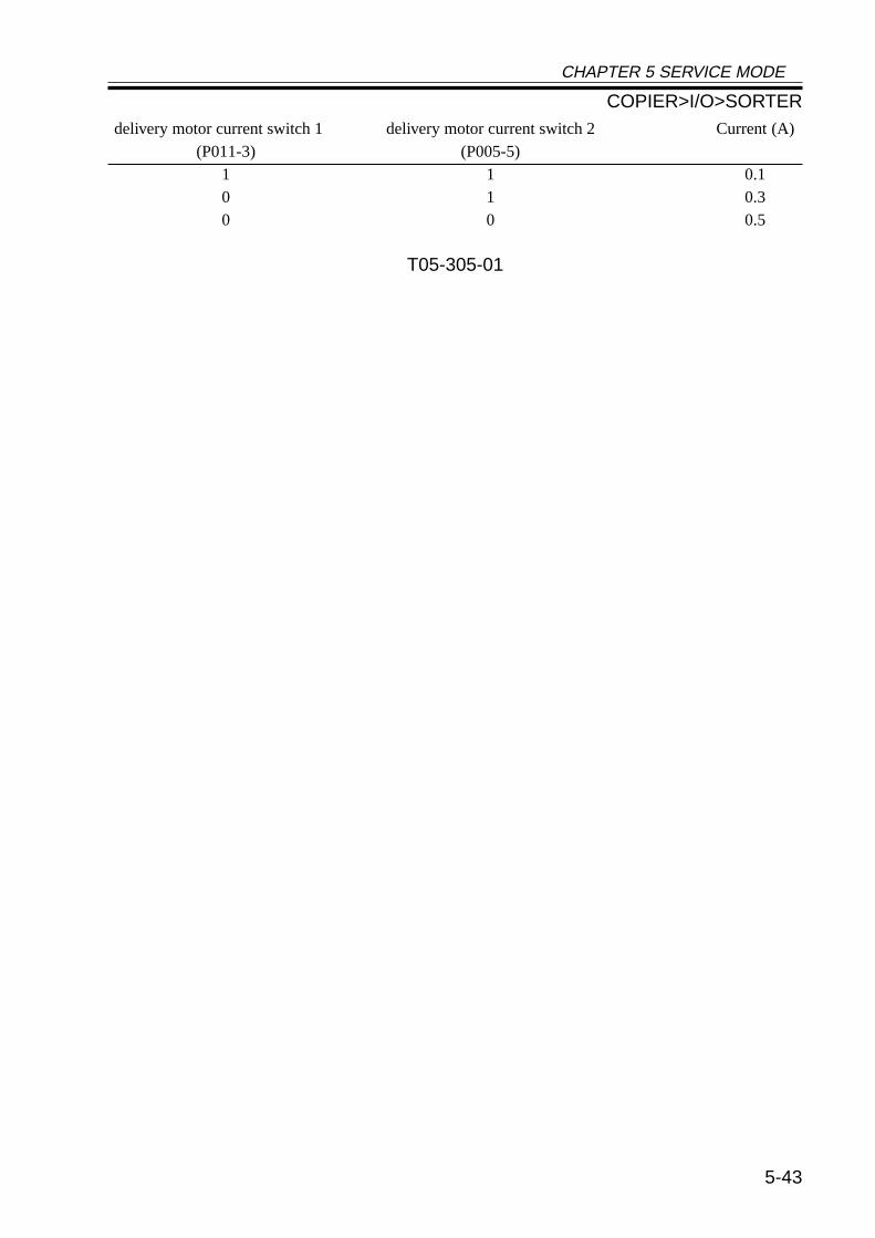
CHAPTER 5 SERVICE MODE
5-43
delivery motor current switch 1 delivery motor current switch 2 Current (A)(P011-3) (P005-5)
1 1 0.10 1 0.30 0 0.5
T05-305-01
COPIER>I/O>SORTER
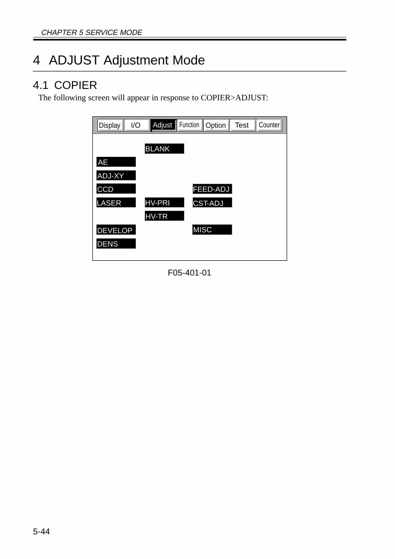
CHAPTER 5 SERVICE MODE
5-44
4 ADJUST Adjustment Mode
4.1 COPIERThe following screen will appear in response to COPIER>ADJUST:
F05-401-01
CounterTestOptionFunctionI/ODisplay
AE
ADJ-XY
CCD
LASER
BLANK
HV-TR
DEVELOP MISC
DENS
HV-PRI CST-ADJ
FEED-ADJ
Adjust
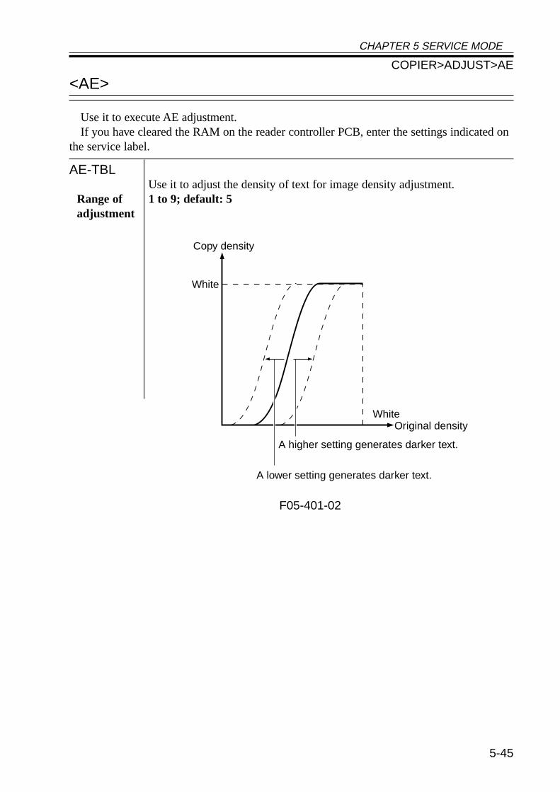
CHAPTER 5 SERVICE MODE
5-45
<AE>
Use it to execute AE adjustment.If you have cleared the RAM on the reader controller PCB, enter the settings indicated on
the service label.
AE-TBLUse it to adjust the density of text for image density adjustment.
Range of 1 to 9; default: 5adjustment
F05-401-02
White
WhiteOriginal density
A lower setting generates darker text.
Copy density
A higher setting generates darker text.
COPIER>ADJUST>AE
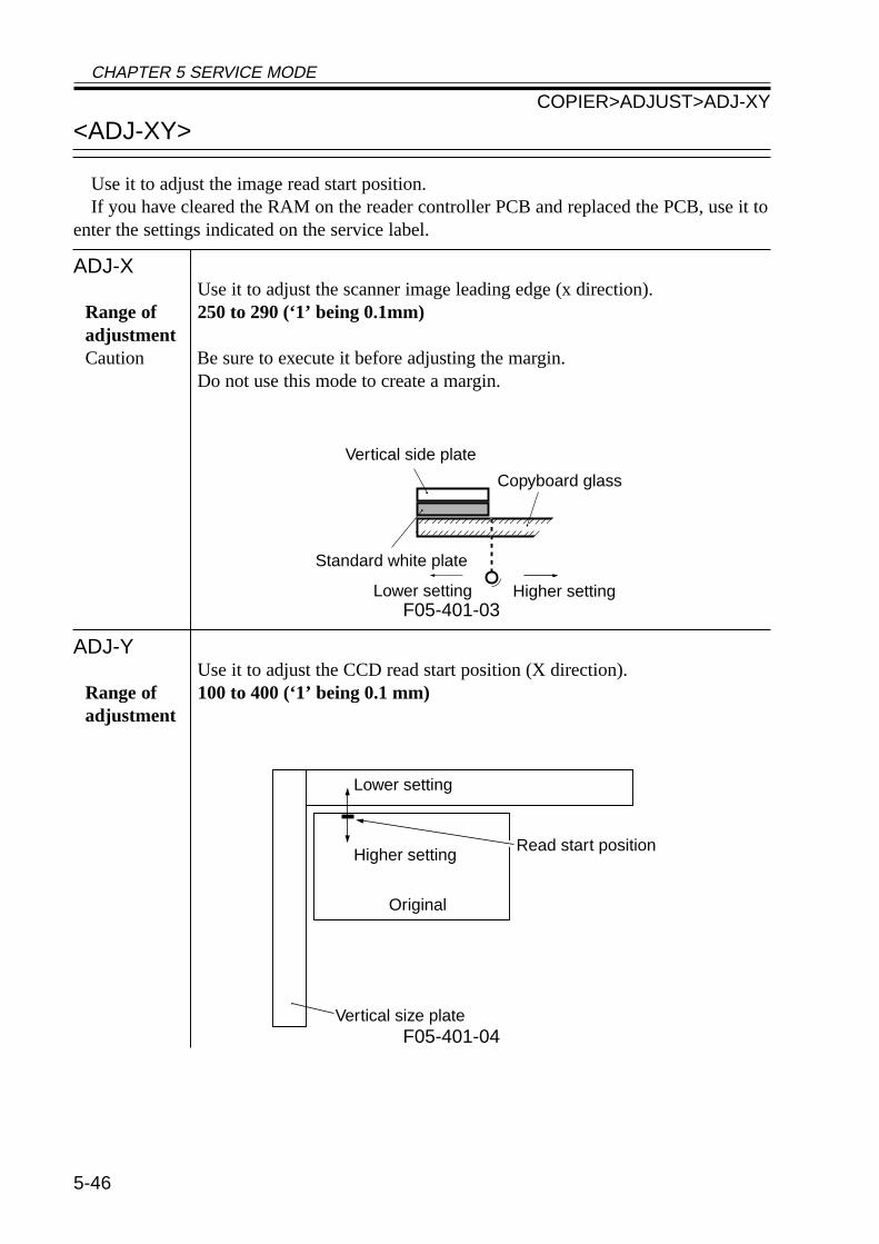
CHAPTER 5 SERVICE MODE
5-46
<ADJ-XY>
Use it to adjust the image read start position.If you have cleared the RAM on the reader controller PCB and replaced the PCB, use it to
enter the settings indicated on the service label.
ADJ-XUse it to adjust the scanner image leading edge (x direction).
Range of 250 to 290 (‘1’ being 0.1mm)adjustmentCaution Be sure to execute it before adjusting the margin.
Do not use this mode to create a margin.
F05-401-03
ADJ-YUse it to adjust the CCD read start position (X direction).
Range of 100 to 400 (‘1’ being 0.1 mm)adjustment
F05-401-04
Vertical side plate
Standard white plate
Higher settingLower setting
Copyboard glass
Lower setting
Higher setting
Original
Vertical size plate
Read start position
COPIER>ADJUST>ADJ-XY
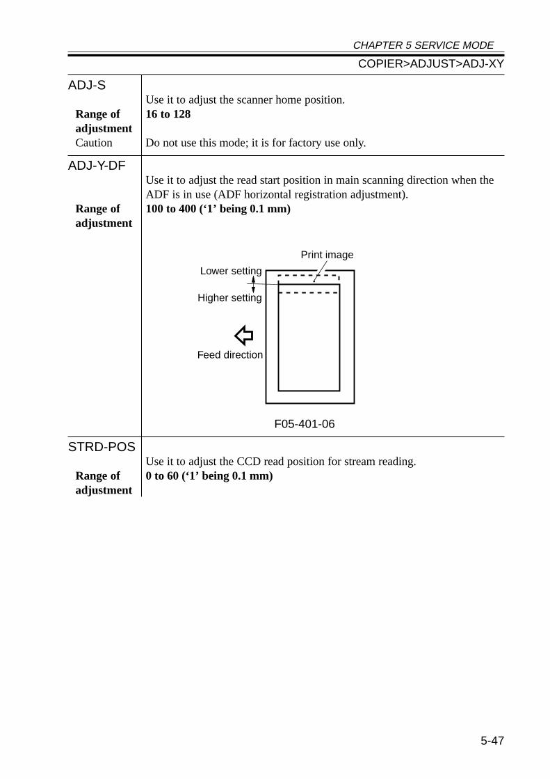
CHAPTER 5 SERVICE MODE
5-47
ADJ-SUse it to adjust the scanner home position.
Range of 16 to 128adjustmentCaution Do not use this mode; it is for factory use only.
ADJ-Y-DFUse it to adjust the read start position in main scanning direction when theADF is in use (ADF horizontal registration adjustment).
Range of 100 to 400 (‘1’ being 0.1 mm)adjustment
F05-401-06
STRD-POSUse it to adjust the CCD read position for stream reading.
Range of 0 to 60 (‘1’ being 0.1 mm)adjustment
Feed direction
Higher setting
Lower setting
Print image
COPIER>ADJUST>ADJ-XY
CHAPTER 5 SERVICE MODE
5-48
<CCD>
Use it to make CCD/shading-related adjustments.If faulty images are generated after the execution of COPIER>FUNCTION>CCD>CCD-
ADJ, enter the settings indicated on the service label.
SH-TRGTUse it to enter the white level target value for shading correction.
SH-PATIOUse it to enter the data on the white level ratio (the standard white plate andthe standard white paper) for shading correction.
EGGN-STUse it to enter the adjustment value for the edge gain correction start posi-tion of the CCD.
EGGN-ENDUse it to enter the adjustment value for the end gain correction end positionof the CCD.
COPIER>ADJUST>LASER
<LASER>
Use it to adjust the laser output.If you have cleared the RAM on the DC controller PCB and replaced the PCB, enter the
settings indicated on the service label.
PVE-OFSTUse it to adjust the point of laser exposure.
Range of -600 to +600 (a change of ‘23’ causes a shift of about 1 mm; a higheradjustment setting shifts the image toward the rear in main scanning direction)
LA-OFFUse it to adjust the laser trailing edge OFF timing when non-default paper isused.
Range of 0 to 600adjustment (a higher setting increases the time interval up to de-activation)
POWERUse it to adjust the laser paper for non-potential control mode.
Range of 0 to 255adjustment
COPIER>ADJUST>CCD
CHAPTER 5 SERVICE MODE
5-49
<DEVELOP>
Use it to adjust the developing bias output.
DE-DCUse it to enter the adjustment value for the DC component of the develop-ing bias within the image area.
Range of 0 to 255 (a higher setting generates lighter images)adjustmentCaution If you have replaced the DC controller PCB, be sure to enter the settings in-
dicated on the service label.
DE-OFSTUse it to enter the offset value for the DC component of the developing bias.
Range of 0 to 255 (a higher setting generates lighter images)adjustmentCaution • be sure to keep the setting between +30 and -30.
• If you have replaced the composite power supply PCB, be sure to enter thesettings indicated on the label attached to the new PCB (case).
COPIER>ADJUST>DEVELOP
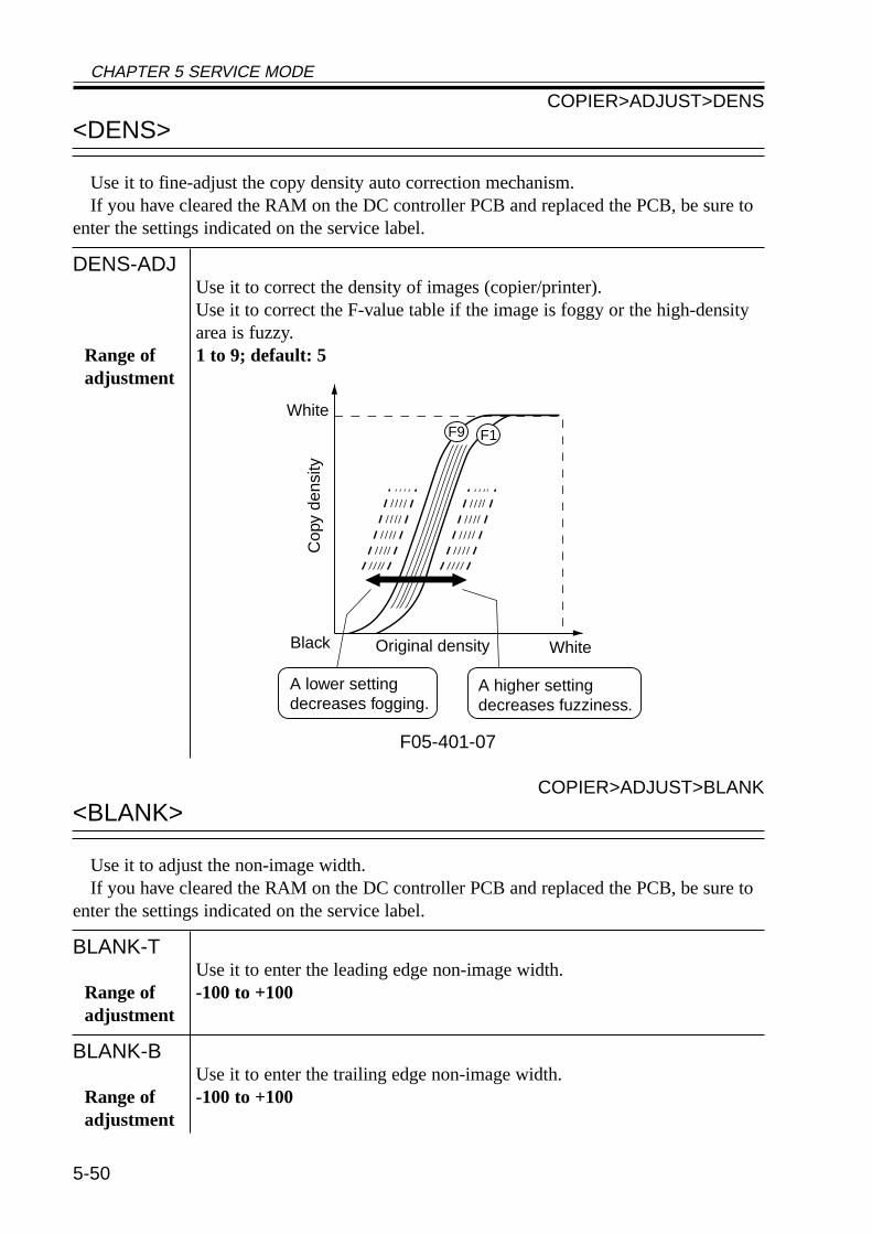
CHAPTER 5 SERVICE MODE
5-50
<DENS>
Use it to fine-adjust the copy density auto correction mechanism.If you have cleared the RAM on the DC controller PCB and replaced the PCB, be sure to
enter the settings indicated on the service label.
DENS-ADJUse it to correct the density of images (copier/printer).Use it to correct the F-value table if the image is foggy or the high-densityarea is fuzzy.
Range of 1 to 9; default: 5adjustment
F05-401-07
COPIER>ADJUST>BLANK
<BLANK>
Use it to adjust the non-image width.If you have cleared the RAM on the DC controller PCB and replaced the PCB, be sure to
enter the settings indicated on the service label.
BLANK-TUse it to enter the leading edge non-image width.
Range of -100 to +100adjustment
BLANK-BUse it to enter the trailing edge non-image width.
Range of -100 to +100adjustment
White
Cop
y de
nsity
Black Original density White
F9 F1
A lower setting decreases fogging.
A higher setting decreases fuzziness.
COPIER>ADJUST>DENS
CHAPTER 5 SERVICE MODE
5-51
<HV-PRI>
Use it to adjust the output of the primary charging assembly.If you have cleared the RAM on the DC controller PCB and replaced the PCB, be sure to
enter the setting indicated on the service label.
P-DCUse it to enter the adjustment value for the primary charging DC componentof the image area.
Range of 0 to 255adjustmentCaution
P-ACUse it to enter the adjustment value for the primary charging AC componentof the image area.
Range of 0 to 255adjustment
AGS-GAINUse it to adjust the gain adjustment value for the photosensitive drum resis-tance detection control (APVC) mechanism.
Caution If you have replaced the composite power supply PCB, be sure to enter thesettings indicated on the label attached to the new PCB (case).
Range of 0 to 255adjustment
AGS-OFSTUse it to enter the offset adjustment value for the photosensitive drum resis-tance detection control (APVC) mechanism.
Caution If you have replaced the composite power supply PCB, be sure to enter thesettings indicated on the label attached to the new PCB (case).
Range of 0 to 255adjustment
COPIER>ADJUST>HV-PRI
CHAPTER 5 SERVICE MODE
5-52
OFST1-DCUse it to enter the adjustment value for the primary charging DC offset 1.
Caution If you have replaced the composite power supply PCB, be sure to enter thesettings indicated on the label attached to the new PCB (case).
Range of 0 to 255 (a lower setting generates lighter images)adjustment
OFST1-ACUse it to enter the adjustment value for the primary charging AC offset 1.
Caution If you have replaced the composite power supply PCB, be sure to enter thesettings indicated on the label attached to the new PCB (case).
Range of 0 to 255adjustment
P-AC2Use it to enter the adjustment value for the primary charging AC component2 for the image area.
Range of 0 to 255adjustment
P-AC3Use it to enter the adjustment value for the primary charging AC component3 for the image area.
Range of 0 to 255adjustment
COPIER>ADJUST>HV-PRI
CHAPTER 5 SERVICE MODE
5-53
<HV-TR>
User it to adjust the output for transfer charging/pre-transfer.If you have cleared the RAM on the DC controller PCB and replaced the PCB, be sure to
enter the settings indicated on the service label.
TR-N1Use it to enter the output adjustment value for the transfer charging current(for plain paper, printing on one side or the 1st side of a double-sided print).
Range of 0 to 10adjustment
TR-N2Use it to enter the output adjustment value for the transfer bias (for plainpaper, the 2nd side of a double-sided print).
Range of 0 to 10adjustment
TR-OFSTUse it to enter the output adjustment offset value for transfer charging cur-rent.
Range of 0 to 255adjustment
TR-SPPUse it to enter the output adjustment bias value of thick paper transfer (forthick paper, printing on one side or printing on the 1st/2nd side of a double-sided print).• A higher setting causes stronger effects.
Range of 0 to 10adjustment
COPIER>ADJUST>HV-TR
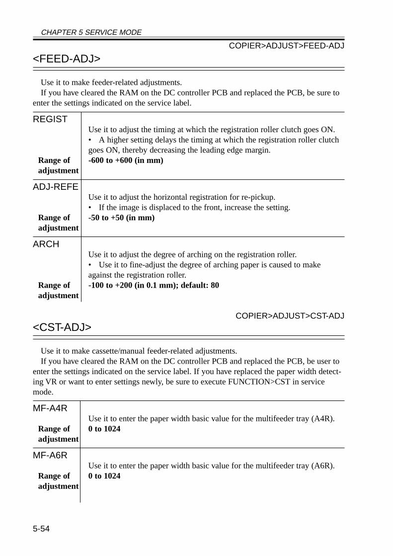
CHAPTER 5 SERVICE MODE
5-54
<FEED-ADJ>
Use it to make feeder-related adjustments.If you have cleared the RAM on the DC controller PCB and replaced the PCB, be sure to
enter the settings indicated on the service label.
REGISTUse it to adjust the timing at which the registration roller clutch goes ON.• A higher setting delays the timing at which the registration roller clutchgoes ON, thereby decreasing the leading edge margin.
Range of -600 to +600 (in mm)adjustment
ADJ-REFEUse it to adjust the horizontal registration for re-pickup.• If the image is displaced to the front, increase the setting.
Range of -50 to +50 (in mm)adjustment
ARCHUse it to adjust the degree of arching on the registration roller.• Use it to fine-adjust the degree of arching paper is caused to makeagainst the registration roller.
Range of -100 to +200 (in 0.1 mm); default: 80adjustment
COPIER>ADJUST>CST-ADJ
<CST-ADJ>
Use it to make cassette/manual feeder-related adjustments.If you have cleared the RAM on the DC controller PCB and replaced the PCB, be user to
enter the settings indicated on the service label. If you have replaced the paper width detect-ing VR or want to enter settings newly, be sure to execute FUNCTION>CST in servicemode.
MF-A4RUse it to enter the paper width basic value for the multifeeder tray (A4R).
Range of 0 to 1024adjustment
MF-A6RUse it to enter the paper width basic value for the multifeeder tray (A6R).
Range of 0 to 1024adjustment
COPIER>ADJUST>FEED-ADJ
CHAPTER 5 SERVICE MODE
5-55
MF-A4Use it to enter the paper width basic value for the multifeeder tray (A4).
Range of 0 to 1024adjustment
COPIER>ADJUST>FIXING
<FIXING>
Use it to make fixing-relating adjustments.If you have cleared the RAM on the DC controller PCB and replaced the PCB, be sure to
enter the settings indicated on the service label.
FX-FL-THUse it to enter the fine-adjusted value for the fixing film speed for thick pa-per.• Use it to make fine-adjustments in relation to the target control speed ofthe fixing film when thick paper is selected.
Range of -3 to +3 (in msec; default: 0)adjustment
FX-FL-SPUse it to enter the fine adjustment value for the fixing film when plain paperis selected.• Use it to fine-adjust the target control speed for the fixing film whenplain paper is selected.
Range of -3 to +3 (in msec; default: 0)adjustment
COPIER>ADJUST>CST-ADJ
CHAPTER 5 SERVICE MODE
5-56
<MISC>
Use it to make other adjustments.If you have cleared the RAM on the DC controller PCB and replaced the PCB, be sure to
enter the settings indicated on the service label.
C1-ADJ-YUse it to enter the cassette 1 horizontal registration adjustment value.• Enter a value in relation to the registered value for the laser write startposition for paper picked up from the cassette 1.
Range of -32 to + 32 (in steps; ‘1’ step being 0.16 mm)adjustment
C2-ADJ-YUse it to enter the cassette 2 horizontal registration adjustment value.• Enter a value in relation to the registered value for the laser write startposition for paper picked up from the cassette 2.
Range of -32 to +32 (in steps; ‘1’ step being 0.16mm)adjustment
C3-ADJ-YUse it to enter the cassette 3 horizontal registration adjustment value.• Enter a value in relation to the registered value for the laser write startposition for paper picked up from the cassette 3.
Range of -32 to +32 (in steps; ‘1’ step being 0.16mm)adjustment
C4-ADJ-YUse it to enter the cassette 4 horizontal registration adjustment value.• Enter a value in relation to the registered value for the laser write startposition for paper picked up from the cassette 4.
Range of -32 to +32 (in steps; ‘1’ step being 0.16mm)adjustment
MF-ADJ-YUse it to enter the horizontal registration adjustment value for themultifeeder.• Use it to enter a laser write start position value in relation to the regis-tered value for paper picked up from the multifeeder tray.
Range of -32 to +32 (in steps; ‘1’ step being 0.16mm)adjustment
COPIER>ADJUST>MISC
CHAPTER 5 SERVICE MODE
5-57
DK-ADJ-YUse it to enter the horizontal registration adjustment value for the paperdeck.• Use it to enter a laser write position value in relation to the registeredvalue for paper picked up from the paper deck.
Range of -32 to +32 (in steps; 1 step being 0.16 mm)adjustment
FRAME-XUse it to enter a zoom fine-adjustment value (sub scanning direction).• Use it to enter an extra length of the image in sub scanning direction inrelation to the registered value.
Range of -50 to +50 (-1% to +1%)adjustment
FRAME-YUse it to enter the zoom fine-adjustment value (main scanning direction).• Use it to enter an extra length for the image in main scanning directionin relation to the register value.
Range of -50 to +50 (-1% to +1%)adjustment
IMG-DLYUse it to enter a fine-adjustment value (sub scanning direction) for imagedelay.• Use it to make fine adjustments for the length of image delay in subscanning direction when sending image data from the main controller PCBto the DC controller PCB.
Range of -20 to +20 (in 0.1 mm)adjustment
COPIER>ADJUST>MISC
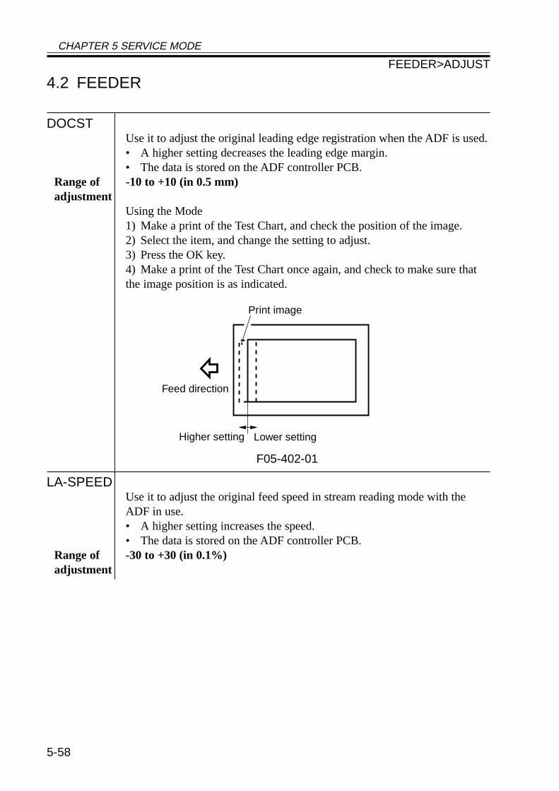
CHAPTER 5 SERVICE MODE
5-58
4.2 FEEDER
DOCSTUse it to adjust the original leading edge registration when the ADF is used.• A higher setting decreases the leading edge margin.• The data is stored on the ADF controller PCB.
Range of -10 to +10 (in 0.5 mm)adjustment
Using the Mode1) Make a print of the Test Chart, and check the position of the image.2) Select the item, and change the setting to adjust.3) Press the OK key.4) Make a print of the Test Chart once again, and check to make sure thatthe image position is as indicated.
F05-402-01
LA-SPEEDUse it to adjust the original feed speed in stream reading mode with theADF in use.• A higher setting increases the speed.• The data is stored on the ADF controller PCB.
Range of -30 to +30 (in 0.1%)adjustment
Feed direction
Higher setting Lower setting
Print image
FEEDER>ADJUST
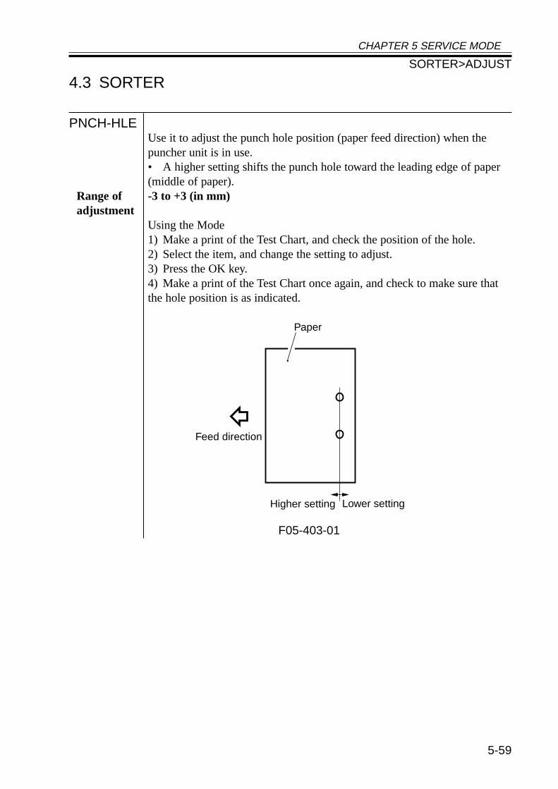
CHAPTER 5 SERVICE MODE
5-59
4.3 SORTER
PNCH-HLEUse it to adjust the punch hole position (paper feed direction) when thepuncher unit is in use.• A higher setting shifts the punch hole toward the leading edge of paper(middle of paper).
Range of -3 to +3 (in mm)adjustment
Using the Mode1) Make a print of the Test Chart, and check the position of the hole.2) Select the item, and change the setting to adjust.3) Press the OK key.4) Make a print of the Test Chart once again, and check to make sure thatthe hole position is as indicated.
F05-403-01
Feed direction
Higher setting Lower setting
Paper
SORTER>ADJUST
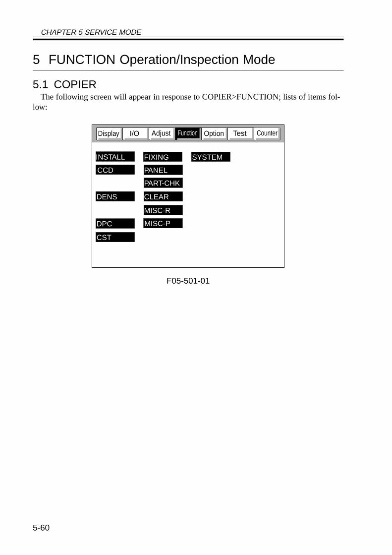
CHAPTER 5 SERVICE MODE
5-60
5 FUNCTION Operation/Inspection Mode
5.1 COPIERThe following screen will appear in response to COPIER>FUNCTION; lists of items fol-
low:
F05-501-01
CounterTestOptionI/ODisplay
CCD
INSTALL
DENS
FIXING SYSTEM
MISC-P
CST
DPC
MISC-R
CLEAR
PART-CHK
PANEL
Adjust Function
CHAPTER 5 SERVICE MODE
5-61
<INSTALL>
Use it as part of installation work.
TONER-SUse it to stir the toner inside the developing assembly.
Caution • Check to make sure that the developing assembly is securely mountedbefore pressing the OK key.• Do not execute any operation. (The Stop key may be pressed.)Using the Mode1) Select <TONER-S> to highlight; then, press the OK key.2) The machine stirs toner (about 4 min), during which time a count-downis indicated to the right of <TONER-S> from 240 to 0.3) The machine automatically stops after stirring toner.
STRD-POSUse it to execute automatic adjustment of the CCD read position in streammode.
Caution • Execute this mode when installing the ADF or if you have removed andthen installed the ADF once again.Using the Mode1) Select <STRD-POS> to highlight; then, press the OK key.• The machine executes automatic adjustment.2) The machine stops operation automatically after adjustment.3) The settings under COPIER>ADJUST>ADJ-XY>STRD-POS is up-dated. Record the new settings to the service label.
CARDUse it when installing the card reader.Using the ModeEnter the number of the card to use. 1 to 2701 (default: 1; as many as 300cards may be used starting with the entered number)Use it to initialize card control information:• initializing the card names (group ID; starting with the entered number).• initializing ID numbers for cards.
COPIER>FUNCTION>INSTALL
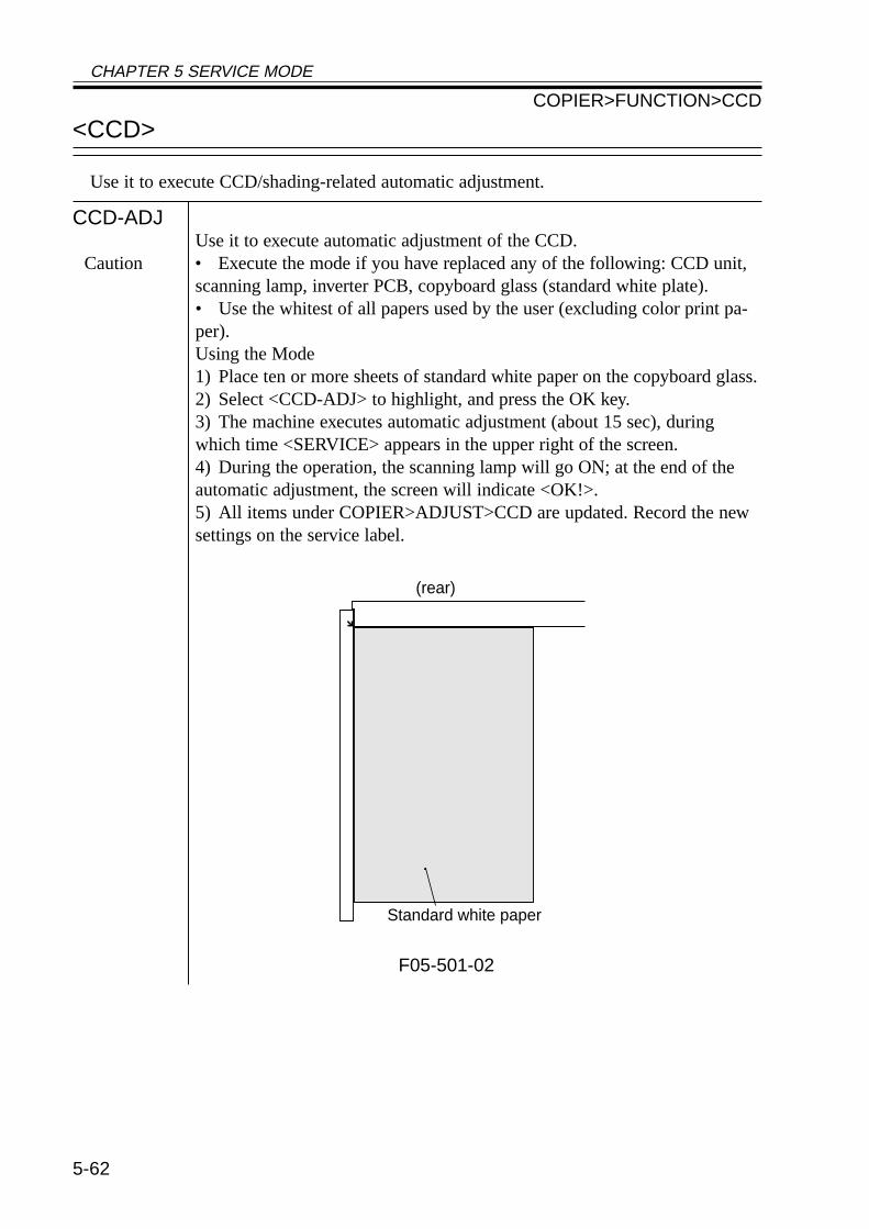
CHAPTER 5 SERVICE MODE
5-62
<CCD>
Use it to execute CCD/shading-related automatic adjustment.
CCD-ADJUse it to execute automatic adjustment of the CCD.
Caution • Execute the mode if you have replaced any of the following: CCD unit,scanning lamp, inverter PCB, copyboard glass (standard white plate).• Use the whitest of all papers used by the user (excluding color print pa-per).Using the Mode1) Place ten or more sheets of standard white paper on the copyboard glass.2) Select <CCD-ADJ> to highlight, and press the OK key.3) The machine executes automatic adjustment (about 15 sec), duringwhich time <SERVICE> appears in the upper right of the screen.4) During the operation, the scanning lamp will go ON; at the end of theautomatic adjustment, the screen will indicate <OK!>.5) All items under COPIER>ADJUST>CCD are updated. Record the newsettings on the service label.
F05-501-02
(rear)
Standard white paper
COPIER>FUNCTION>CCD
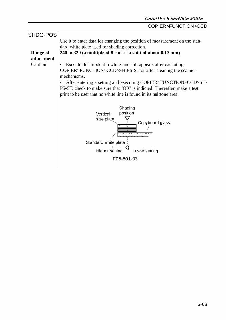
CHAPTER 5 SERVICE MODE
5-63
SHDG-POSUse it to enter data for changing the position of measurement on the stan-dard white plate used for shading correction.
Range of 240 to 320 (a multiple of 8 causes a shift of about 0.17 mm)adjustmentCaution • Execute this mode if a white line still appears after executing
COPIER>FUNCTION>CCD>SH-PS-ST or after cleaning the scannermechanisms.• After entering a setting and executing COPIER>FUNCTION>CCD>SH-PS-ST, check to make sure that ‘OK’ is indicted. Thereafter, make a testprint to be user that no white line is found in its halftone area.
F05-501-03
Verticalsize plate
Standard white plate
Lower settingHigher setting
Copyboard glass
Shadingposition
COPIER>FUNCTION>CCD
CHAPTER 5 SERVICE MODE
5-64
SH-PS-STUse it to execute optimum position auto adjustment for the standard whiteplate for shading correction.
Caution • You must execute COPIER>FUNCTION>CCD>CCD-ADJ before ex-ecuting this move.• Execute this mode if you have replaced the copyboard glass (standardwhite plate) or a white line is noted in halftone areas.Using the Mode1) Clean the back of the copyboard glass.2) Open the ADF (copyboard cover).3) Select <SH-PS-ST> to highlight, and press the OK key.4) The machine executes automatic adjustment (about 10 sec).5) When done, the machine stops automatically indicating the result (OK/NG).• If ‘NG’ is indicated, perform the following, and execute the mode onceagain:a. Is the ADF (copyboard cover) open?b Is the copyboard glass mounted correctly?c. Is the standard white plate (attached to the copyboard glass) normal?d. Does the scanning lamp go ON?6) The items under COPIER>ADJUST>ADJ-XY and ADJ-S are updated.Record the new settings on the service label.
COPIER>FUNCTION>CCD
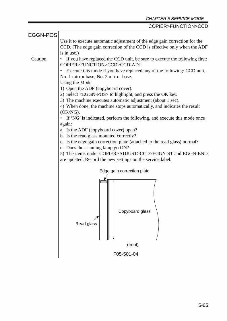
CHAPTER 5 SERVICE MODE
5-65
EGGN-POSUse it to execute automatic adjustment of the edge gain correction for theCCD. (The edge gain correction of the CCD is effective only when the ADFis in use.)
Caution • If you have replaced the CCD unit, be sure to execute the following first:COPIER>FUNCTION>CCD>CCD-ADJ.• Execute this mode if you have replaced any of the following: CCD unit,No. 1 mirror base, No. 2 mirror base.Using the Mode1) Open the ADF (copyboard cover).2) Select <EGGN-POS> to highlight, and press the OK key.3) The machine executes automatic adjustment (about 1 sec).4) When done, the machine stops automatically, and indicates the result(OK/NG).• If ‘NG’ is indicated, perform the following, and execute this mode onceagain:a. Is the ADF (copyboard cover) open?b. Is the read glass mounted correctly?c. Is the edge gain correction plate (attached to the read glass) normal?d. Does the scanning lamp go ON?5) The items under COPIER>ADJUST>CCD>EGGN-ST and EGGN-ENDare updated. Record the new settings on the service label.
F05-501-04
Edge gain correction plate
Copyboard glass
(front)
Read glass
COPIER>FUNCTION>CCD
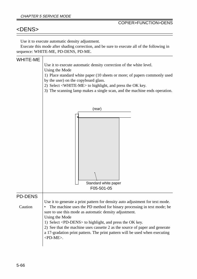
CHAPTER 5 SERVICE MODE
5-66
<DENS>
Use it to execute automatic density adjustment.Execute this mode after shading correction, and be sure to execute all of the following in
sequence: WHITE-ME, PD-DENS, PD-ME.
WHITE-MEUse it to execute automatic density correction of the white level.Using the Mode1) Place standard white paper (10 sheets or more; of papers commonly usedby the user) on the copyboard glass.2) Select <WHITE-ME> to highlight, and press the OK key.3) The scanning lamp makes a single scan, and the machine ends operation.
F05-501-05
PD-DENSUse it to generate a print pattern for density auto adjustment for text mode.
Caution • The machine uses the PD method for binary processing in text mode; besure to use this mode as automatic density adjustment.Using the Mode1) Select <PD-DENS> to highlight, and press the OK key.2) See that the machine uses cassette 2 as the source of paper and generatea 17-gradation print pattern. The print pattern will be used when executing<PD-ME>.
(rear)
Standard white paper
COPIER>FUNCTION>DENS
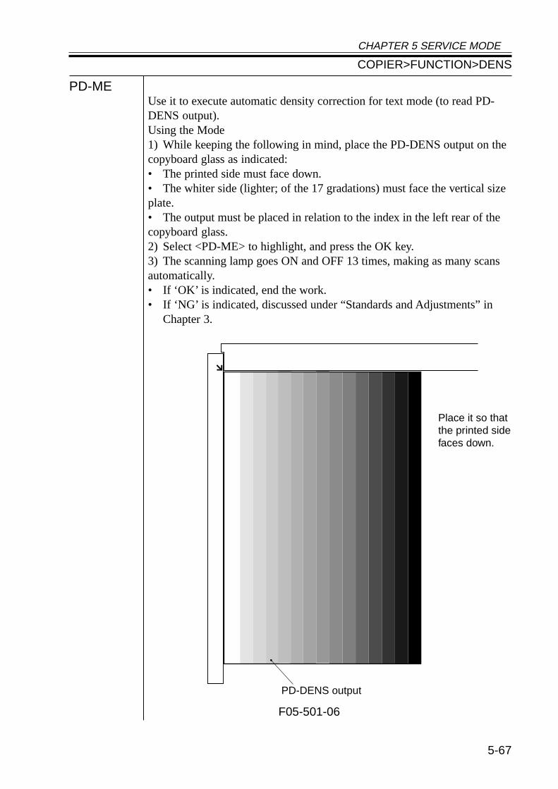
CHAPTER 5 SERVICE MODE
5-67
PD-MEUse it to execute automatic density correction for text mode (to read PD-DENS output).Using the Mode1) While keeping the following in mind, place the PD-DENS output on thecopyboard glass as indicated:• The printed side must face down.• The whiter side (lighter; of the 17 gradations) must face the vertical sizeplate.• The output must be placed in relation to the index in the left rear of thecopyboard glass.2) Select <PD-ME> to highlight, and press the OK key.3) The scanning lamp goes ON and OFF 13 times, making as many scansautomatically.• If ‘OK’ is indicated, end the work.• If ‘NG’ is indicated, discussed under “Standards and Adjustments” in
Chapter 3.
F05-501-06
Place it so thatthe printed sidefaces down.
PD-DENS output
COPIER>FUNCTION>DENS
CHAPTER 5 SERVICE MODE
5-68
<DPC>
Use it to execute potential-related operations.
D-GAMMAUse it to execute photosensitive drum resistance measurement control(APVC).
Caution Use this mode only for the following; do not rely on this mode unless nec-essary:• When making adjustments after replacing the drum unit.• When isolating the cause when copy density automatic adjustment (PD-ME) ends in NG.• When obtaining an idea of the life of the drum.Using the Mode1) Select the item, and press the OK key.2) The machine generates a blank copy and ends automatically.3) See that the machine indicates the result of measurement underDISPLAY>HV-STS>PRIMARY.
COPIER>FUNCTION>CST
<CST>
Use it to execute size automatic adjustment for the multifeeder.
MF-A4RMF-A6RMF-A4
Use it to adjust the paper width basic value for the multifeeder.A4R: width: 210 mm, A6R width: 105 mm, A4 width: 297 mm
Caution To make fine-adjustments after entering the basic value, use ADJUST>CST-ADJ>MF-A4R, MF-A6R, MF-A4.Using the Mode1) Place A4R paper in the multifeeder, and adjust the side guide to A4R.2) Select <MF-A4R> to highlight, and press the OK key.• The machine executes automatic adjustment and stores the value.3) Likewise, perform steps 1. and 2. for A6R and A4.
COPIER>FUNCTION>DPC
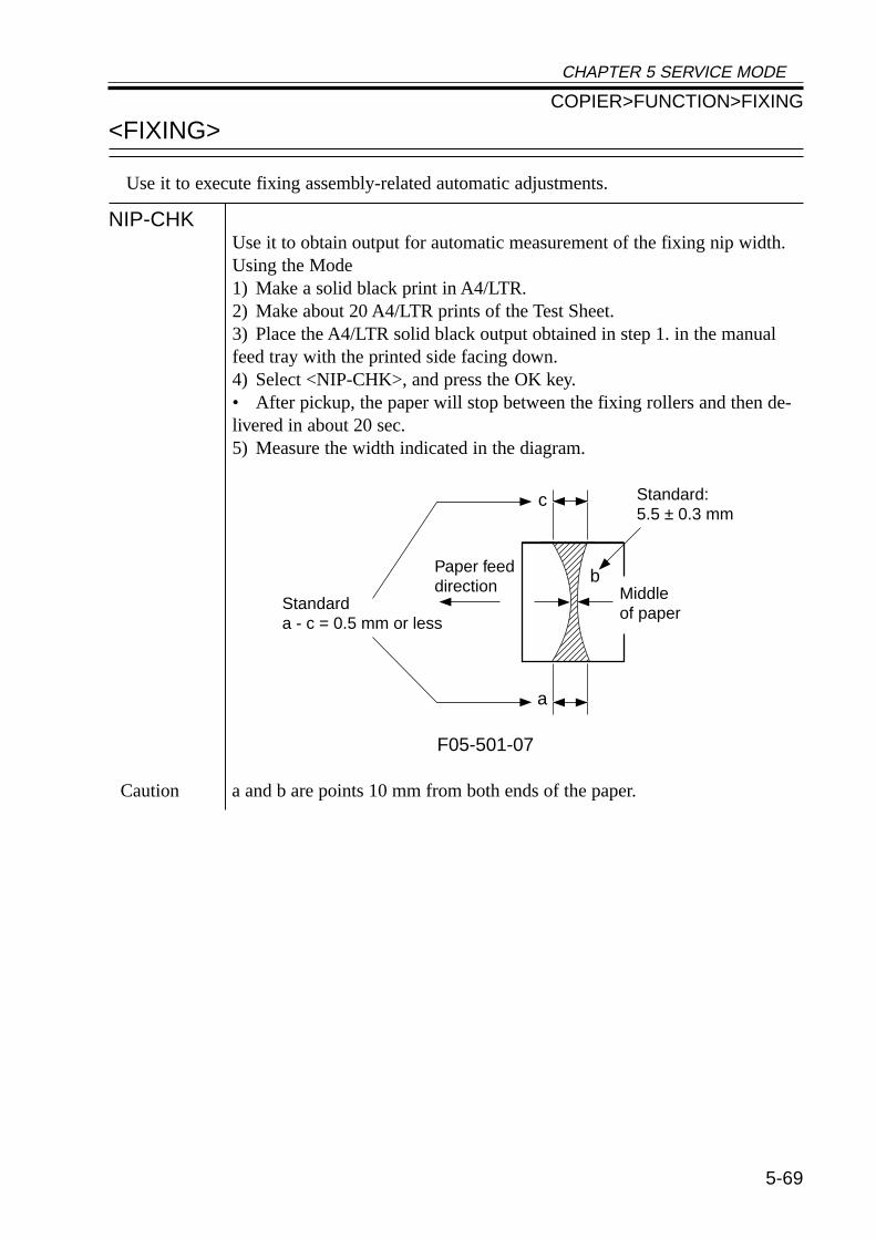
CHAPTER 5 SERVICE MODE
5-69
<FIXING>
Use it to execute fixing assembly-related automatic adjustments.
NIP-CHKUse it to obtain output for automatic measurement of the fixing nip width.Using the Mode1) Make a solid black print in A4/LTR.2) Make about 20 A4/LTR prints of the Test Sheet.3) Place the A4/LTR solid black output obtained in step 1. in the manualfeed tray with the printed side facing down.4) Select <NIP-CHK>, and press the OK key.• After pickup, the paper will stop between the fixing rollers and then de-livered in about 20 sec.5) Measure the width indicated in the diagram.
F05-501-07
Caution a and b are points 10 mm from both ends of the paper.
Paper feeddirection
Standarda - c = 0.5 mm or less
Standard:5.5 ± 0.3 mm
c
a
bMiddleof paper
COPIER>FUNCTION>FIXING
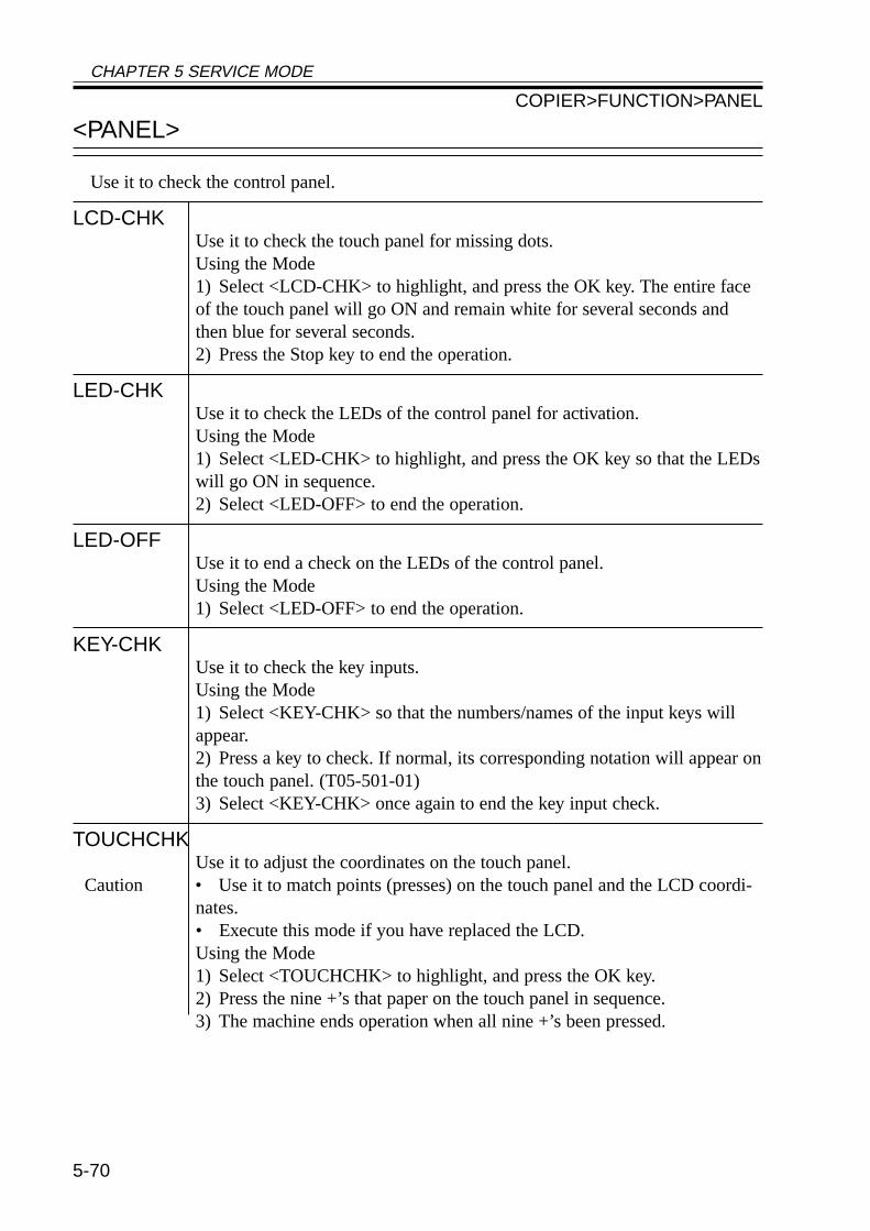
CHAPTER 5 SERVICE MODE
5-70
<PANEL>
Use it to check the control panel.
LCD-CHKUse it to check the touch panel for missing dots.Using the Mode1) Select <LCD-CHK> to highlight, and press the OK key. The entire faceof the touch panel will go ON and remain white for several seconds andthen blue for several seconds.2) Press the Stop key to end the operation.
LED-CHKUse it to check the LEDs of the control panel for activation.Using the Mode1) Select <LED-CHK> to highlight, and press the OK key so that the LEDswill go ON in sequence.2) Select <LED-OFF> to end the operation.
LED-OFFUse it to end a check on the LEDs of the control panel.Using the Mode1) Select <LED-OFF> to end the operation.
KEY-CHKUse it to check the key inputs.Using the Mode1) Select <KEY-CHK> so that the numbers/names of the input keys willappear.2) Press a key to check. If normal, its corresponding notation will appear onthe touch panel. (T05-501-01)3) Select <KEY-CHK> once again to end the key input check.
TOUCHCHKUse it to adjust the coordinates on the touch panel.
Caution • Use it to match points (presses) on the touch panel and the LCD coordi-nates.• Execute this mode if you have replaced the LCD.Using the Mode1) Select <TOUCHCHK> to highlight, and press the OK key.2) Press the nine +’s that paper on the touch panel in sequence.3) The machine ends operation when all nine +’s been pressed.
COPIER>FUNCTION>PANEL
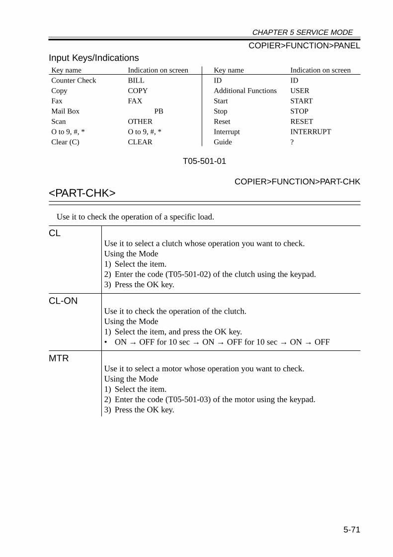
CHAPTER 5 SERVICE MODE
5-71
Input Keys/Indications
T05-501-01
COPIER>FUNCTION>PART-CHK
<PART-CHK>
Use it to check the operation of a specific load.
CLUse it to select a clutch whose operation you want to check.Using the Mode1) Select the item.2) Enter the code (T05-501-02) of the clutch using the keypad.3) Press the OK key.
CL-ONUse it to check the operation of the clutch.Using the Mode1) Select the item, and press the OK key.• ON → OFF for 10 sec → ON → OFF for 10 sec → ON → OFF
MTRUse it to select a motor whose operation you want to check.Using the Mode1) Select the item.2) Enter the code (T05-501-03) of the motor using the keypad.3) Press the OK key.
Key name Indication on screenCounter Check BILLCopy COPYFax FAXMail Box PBScan OTHERO to 9, #, * O to 9, #, *Clear (C) CLEAR
Key name Indication on screenID IDAdditional Functions USERStart STARTStop STOPReset RESETInterrupt INTERRUPTGuide ?
COPIER>FUNCTION>PANEL
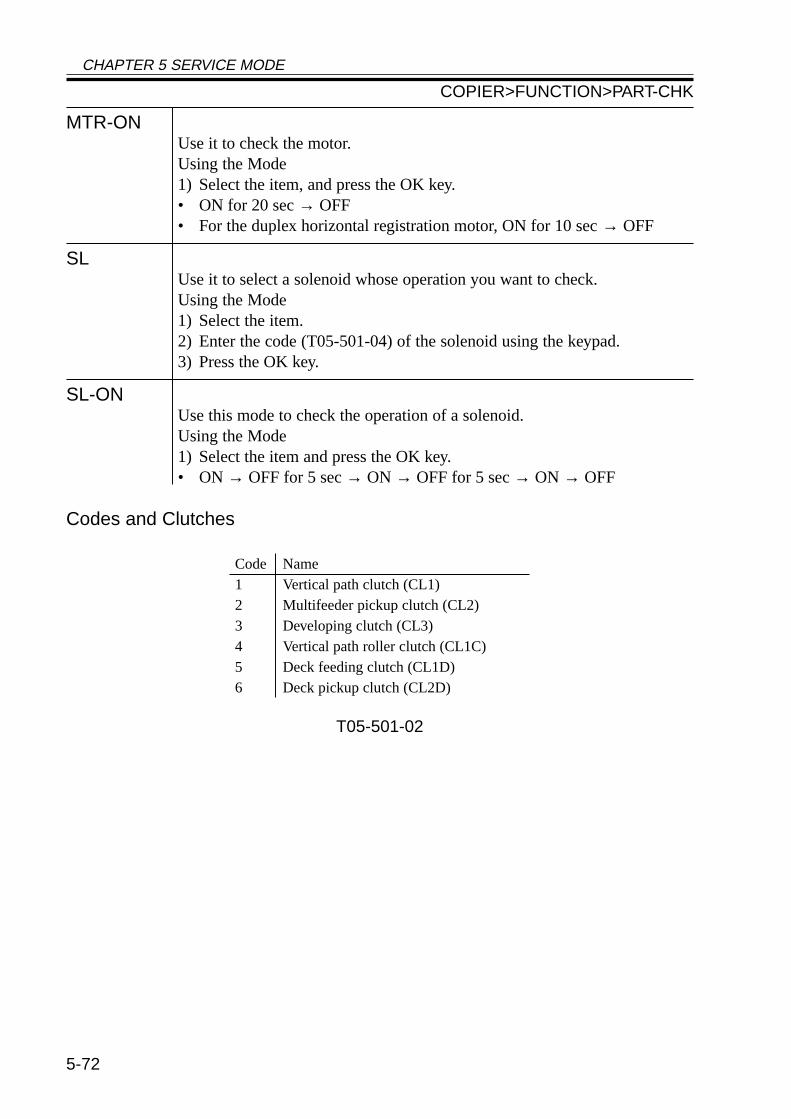
CHAPTER 5 SERVICE MODE
5-72
MTR-ONUse it to check the motor.Using the Mode1) Select the item, and press the OK key.• ON for 20 sec → OFF• For the duplex horizontal registration motor, ON for 10 sec → OFF
SLUse it to select a solenoid whose operation you want to check.Using the Mode1) Select the item.2) Enter the code (T05-501-04) of the solenoid using the keypad.3) Press the OK key.
SL-ONUse this mode to check the operation of a solenoid.Using the Mode1) Select the item and press the OK key.• ON → OFF for 5 sec → ON → OFF for 5 sec → ON → OFF
Codes and Clutches
T05-501-02
Code Name1 Vertical path clutch (CL1)2 Multifeeder pickup clutch (CL2)3 Developing clutch (CL3)4 Vertical path roller clutch (CL1C)5 Deck feeding clutch (CL1D)6 Deck pickup clutch (CL2D)
COPIER>FUNCTION>PART-CHK
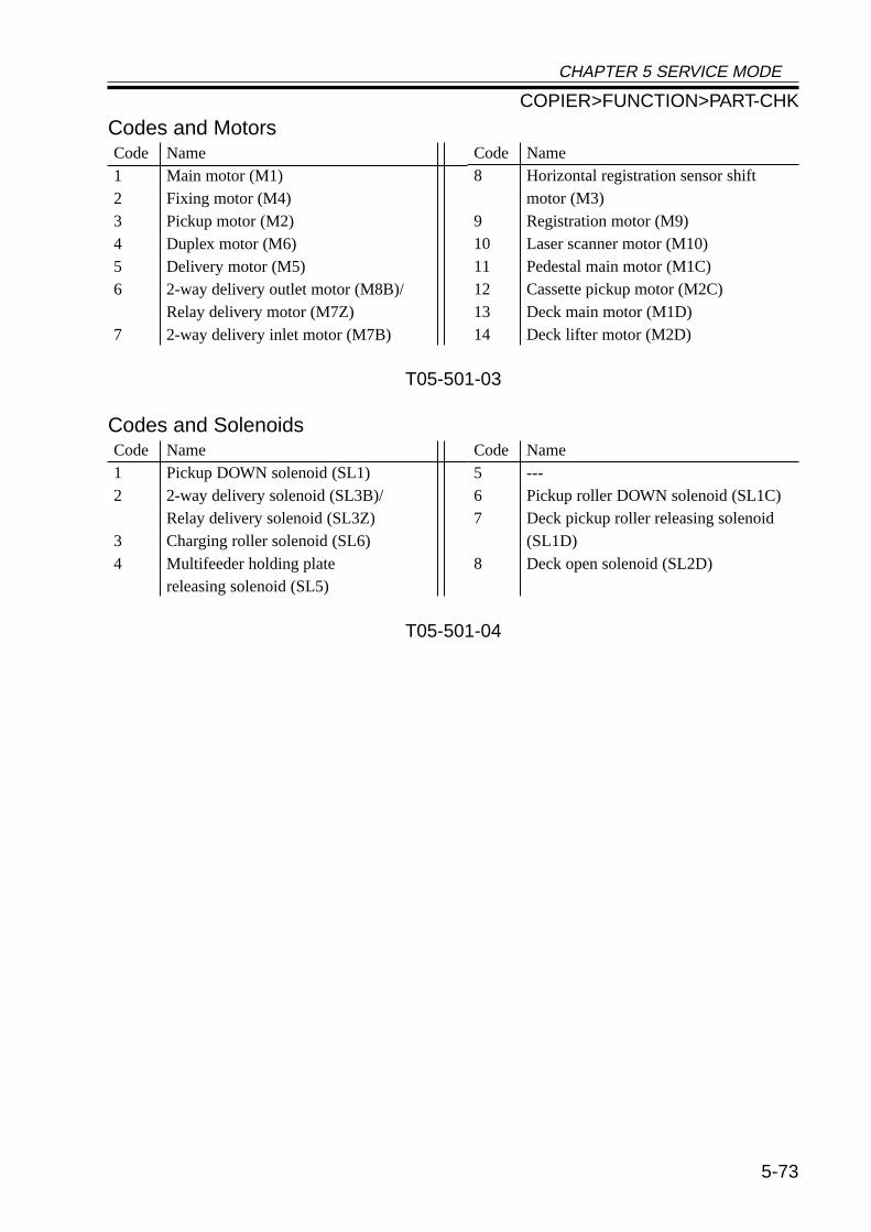
CHAPTER 5 SERVICE MODE
5-73
Codes and Motors
T05-501-03
Codes and Solenoids
T05-501-04
Code Name1 Main motor (M1)2 Fixing motor (M4)3 Pickup motor (M2)4 Duplex motor (M6)5 Delivery motor (M5)6 2-way delivery outlet motor (M8B)/
Relay delivery motor (M7Z)7 2-way delivery inlet motor (M7B)
Code Name8 Horizontal registration sensor shift
motor (M3)9 Registration motor (M9)10 Laser scanner motor (M10)11 Pedestal main motor (M1C)12 Cassette pickup motor (M2C)13 Deck main motor (M1D)14 Deck lifter motor (M2D)
Code Name1 Pickup DOWN solenoid (SL1)2 2-way delivery solenoid (SL3B)/
Relay delivery solenoid (SL3Z)3 Charging roller solenoid (SL6)4 Multifeeder holding plate
releasing solenoid (SL5)
Code Name5 ---6 Pickup roller DOWN solenoid (SL1C)7 Deck pickup roller releasing solenoid
(SL1D)8 Deck open solenoid (SL2D)
COPIER>FUNCTION>PART-CHK
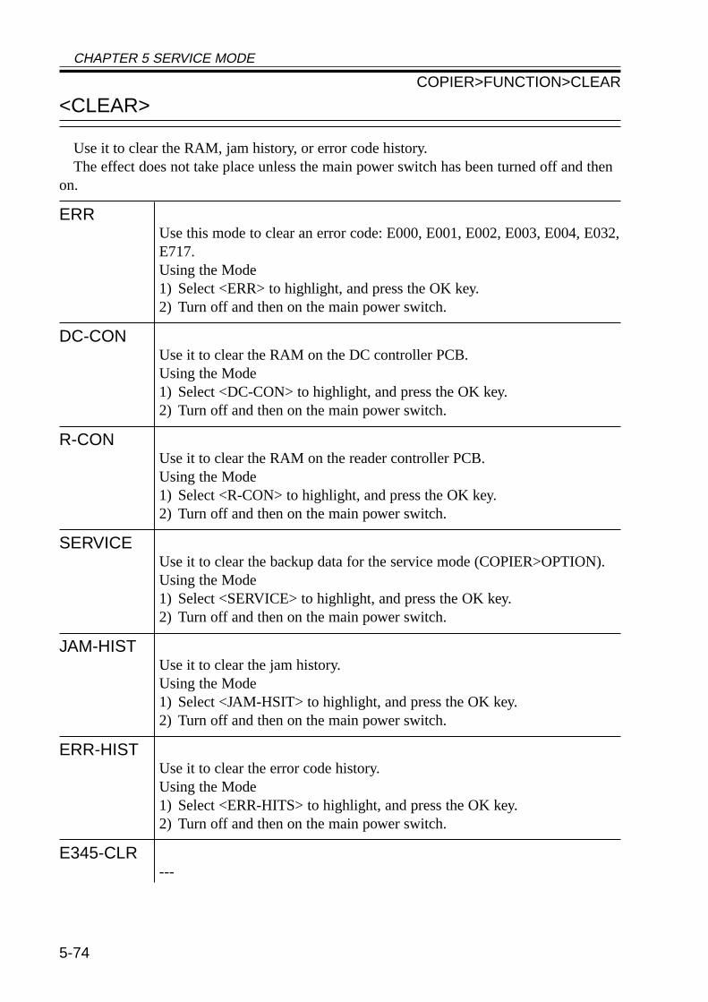
CHAPTER 5 SERVICE MODE
5-74
<CLEAR>
Use it to clear the RAM, jam history, or error code history.The effect does not take place unless the main power switch has been turned off and then
on.
ERRUse this mode to clear an error code: E000, E001, E002, E003, E004, E032,E717.Using the Mode1) Select <ERR> to highlight, and press the OK key.2) Turn off and then on the main power switch.
DC-CONUse it to clear the RAM on the DC controller PCB.Using the Mode1) Select <DC-CON> to highlight, and press the OK key.2) Turn off and then on the main power switch.
R-CONUse it to clear the RAM on the reader controller PCB.Using the Mode1) Select <R-CON> to highlight, and press the OK key.2) Turn off and then on the main power switch.
SERVICEUse it to clear the backup data for the service mode (COPIER>OPTION).Using the Mode1) Select <SERVICE> to highlight, and press the OK key.2) Turn off and then on the main power switch.
JAM-HISTUse it to clear the jam history.Using the Mode1) Select <JAM-HSIT> to highlight, and press the OK key.2) Turn off and then on the main power switch.
ERR-HISTUse it to clear the error code history.Using the Mode1) Select <ERR-HITS> to highlight, and press the OK key.2) Turn off and then on the main power switch.
E345-CLR---
COPIER>FUNCTION>CLEAR
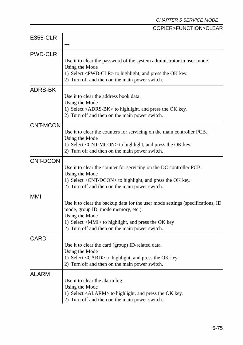
CHAPTER 5 SERVICE MODE
5-75
E355-CLR---
PWD-CLRUse it to clear the password of the system administrator in user mode.Using the Mode1) Select <PWD-CLR> to highlight, and press the OK key.2) Turn off and then on the main power switch.
ADRS-BKUse it to clear the address book data.Using the Mode1) Select <ADRS-BK> to highlight, and press the OK key.2) Turn off and then on the main power switch.
CNT-MCONUse it to clear the counters for servicing on the main controller PCB.Using the Mode1) Select <CNT-MCON> to highlight, and press the OK key.2) Turn off and then on the main power switch.
CNT-DCONUse it to clear the counter for servicing on the DC controller PCB.Using the Mode1) Select <CNT-DCON> to highlight, and press the OK key.2) Turn off and then on the main power switch.
MMIUse it to clear the backup data for the user mode settings (specifications, IDmode, group ID, mode memory, etc.).Using the Mode1) Select <MMI> to highlight, and press the OK key2) Turn off and then on the main power switch.
CARDUse it to clear the card (group) ID-related data.Using the Mode1) Select <CARD> to highlight, and press the OK key.2) Turn off and then on the main power switch.
ALARMUse it to clear the alarm log.Using the Mode1) Select <ALARM> to highlight, and press the OK key.2) Turn off and then on the main power switch.
COPIER>FUNCTION>CLEAR

CHAPTER 5 SERVICE MODE
5-76
<MISC-R>
Checking reader unit-related operations.
SCANLAMPUse it to check the scanning lamp for activation.Using the Mode1) Select <SCANLAMP> to highlight, and press the OK key.2) The scanning lamp goes ON.3) Press the Stop key to turn off the lamp.
COPIER>FUNCTION>MISC-R
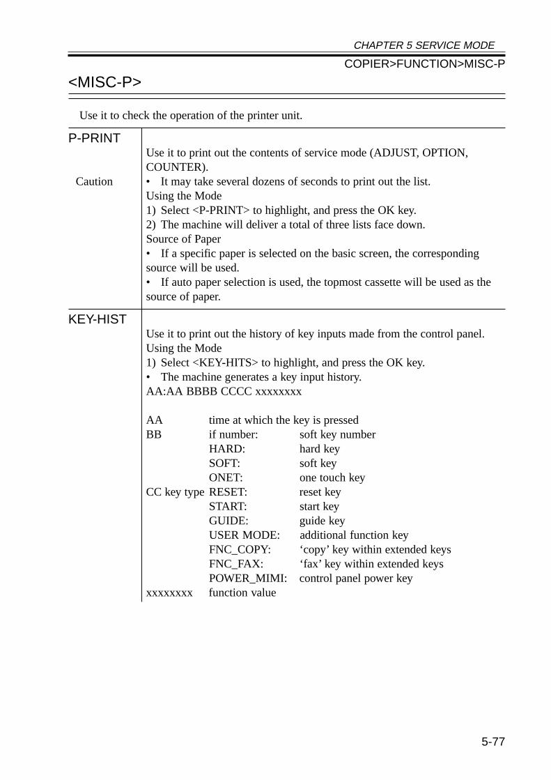
CHAPTER 5 SERVICE MODE
5-77
<MISC-P>
Use it to check the operation of the printer unit.
P-PRINTUse it to print out the contents of service mode (ADJUST, OPTION,COUNTER).
Caution • It may take several dozens of seconds to print out the list.Using the Mode1) Select <P-PRINT> to highlight, and press the OK key.2) The machine will deliver a total of three lists face down.Source of Paper• If a specific paper is selected on the basic screen, the correspondingsource will be used.• If auto paper selection is used, the topmost cassette will be used as thesource of paper.
KEY-HISTUse it to print out the history of key inputs made from the control panel.Using the Mode1) Select <KEY-HITS> to highlight, and press the OK key.• The machine generates a key input history.AA:AA BBBB CCCC xxxxxxxx
AA time at which the key is pressedBB if number: soft key number
HARD: hard keySOFT: soft keyONET: one touch key
CC key type RESET: reset keySTART: start keyGUIDE: guide keyUSER MODE: additional function keyFNC_COPY: ‘copy’ key within extended keysFNC_FAX: ‘fax’ key within extended keysPOWER_MIMI: control panel power key
xxxxxxxx function value
COPIER>FUNCTION>MISC-P
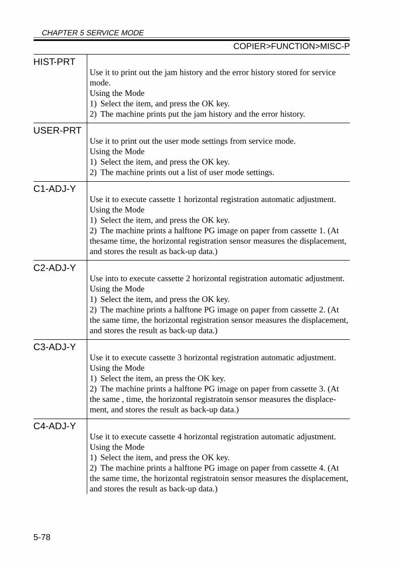
CHAPTER 5 SERVICE MODE
5-78
HIST-PRTUse it to print out the jam history and the error history stored for servicemode.Using the Mode1) Select the item, and press the OK key.2) The machine prints put the jam history and the error history.
USER-PRTUse it to print out the user mode settings from service mode.Using the Mode1) Select the item, and press the OK key.2) The machine prints out a list of user mode settings.
C1-ADJ-YUse it to execute cassette 1 horizontal registration automatic adjustment.Using the Mode1) Select the item, and press the OK key.2) The machine prints a halftone PG image on paper from cassette 1. (Atthesame time, the horizontal registration sensor measures the displacement,and stores the result as back-up data.)
C2-ADJ-YUse into to execute cassette 2 horizontal registration automatic adjustment.Using the Mode1) Select the item, and press the OK key.2) The machine prints a halftone PG image on paper from cassette 2. (Atthe same time, the horizontal registration sensor measures the displacement,and stores the result as back-up data.)
C3-ADJ-YUse it to execute cassette 3 horizontal registration automatic adjustment.Using the Mode1) Select the item, an press the OK key.2) The machine prints a halftone PG image on paper from cassette 3. (Atthe same , time, the horizontal registratoin sensor measures the displace-ment, and stores the result as back-up data.)
C4-ADJ-YUse it to execute cassette 4 horizontal registration automatic adjustment.Using the Mode1) Select the item, and press the OK key.2) The machine prints a halftone PG image on paper from cassette 4. (Atthe same time, the horizontal registratoin sensor measures the displacement,and stores the result as back-up data.)
COPIER>FUNCTION>MISC-P
CHAPTER 5 SERVICE MODE
5-79
MF-ADJ-YUse it to execute multifeeder horizontal registration automatic adjustment.Using the Mode1) Select the item, and press the OK key.2) The machine prints a halftone PG image on paper from the multifeedertray. (At the same time, the horizontal registration sensor measures the dis-placement, and stores the result as back-up data.)
DK-ADJ-YUse it to execute paper deck horizontal registration automatic adjustment.Using the Mode1) Select the item, and press the OK key.2) The machine prints a halftone PG image on paper from the paper deck.(At the same time, the horizontal registration sensor measures the displace-ment, and stores the result as back-up data.)
LBL-PRNTUse it to print out a service label.Using the Mode1) Put paper in the manual feed tray.2) Select the item, and press the OK key.3) The machine prints out a service label.• The label also indicates the settings of ADJUST and OPTION.
PRE-EXPUse it to check the pre-exposure lamp for activation.Using the Mode1) Select the item, and press the OK key.2) The pre-exposure lamp goes ON and remains ON for several seconds,and goes OFF automatically.
COPIER>FUNCTION>MISC-P
CHAPTER 5 SERVICE MODE
5-80
<SYSTEM>
Use it to check system-related operations.
DOWNLOADUse it to switch to system program download mode.
Caution • Use it to download the system program.Using the Mode1) Turn off the machine and the PC.2) Disconnect the network cable from the machine.3) Connect the machine and the PC with a bi-Centronics cable.4) Turn on the PC.5) Turn on the machine.6) Select <DOWNLOAD> to highlight, and press the OK key.7) Use the Service Support Tool to download the data.8) When done, turn off and then on the main power switch.
CHK-TYPEUse it to select a partition number for HD-CHECK.Using the Mode1) Selects the item.2) Selects a partition number using the keypad (0: check and recover entireHDD for faulty sectors, 1: image storage area, 2: general file storage area,3: PDL-related file storage area, 4: firmware storage area).• A general file refers to the following: user settings data, log data, PDLspool data, image data.3) Press the OK key.
HD-CHECKUse it to execute a check and recovery of the partition selection using CHK-TYPE.Using the Mode1) Select the item.2) Press the OK key.3) The machine indicates the result (1: OK, 2: NG (hardware), 3: NG (soft-ware); recovery sensor/alternate sector).
HD-CLEARUse it to initialize the partition selected using CHK-TYPE.
Caution • If ‘0’ or ‘4’ is selected, the executing will be invalid.• If’ ‘1’ is selected, the image control data stored in the SRAM area or thegeneral file storage area will also be initialized.Using the Mode1) Select the item.2) Press the OK key.
COPIER>FUNCTION>SYSTEM
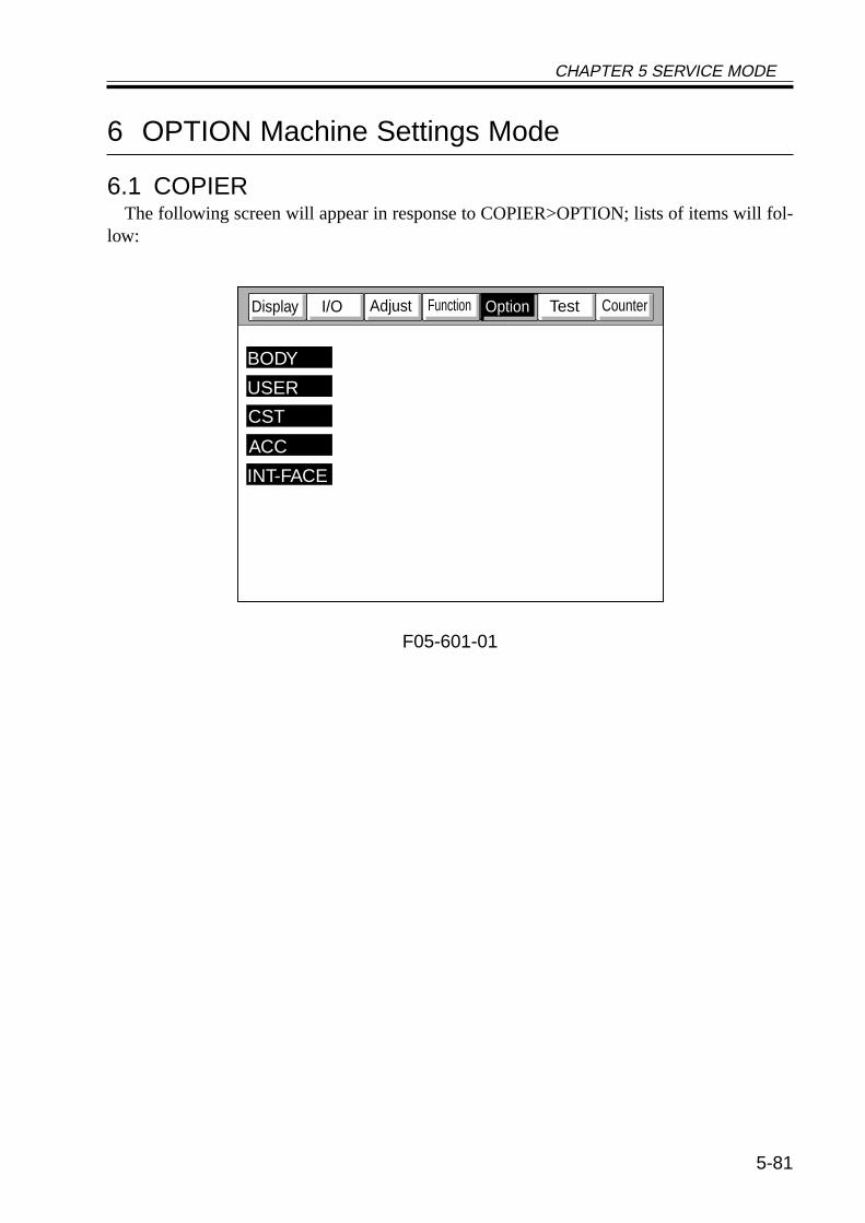
CHAPTER 5 SERVICE MODE
5-81
6 OPTION Machine Settings Mode
6.1 COPIERThe following screen will appear in response to COPIER>OPTION; lists of items will fol-
low:
F05-601-01
CounterTestFunctionAdjustI/ODisplay
BODY
USER
CST
ACC
INT-FACE
Option
CHAPTER 5 SERVICE MODE
5-82
BODY
Use it to make machine-related settings.
MODEL-SZUse it to select the mode of indication by destination and of the ADF origi-nal size detection.
Settings 0: AB (6R5E), 1: INCH (5R4E), 2: A (3R3E), 3: AB/INCH (6R5E)
FIX-CLNUse it to set fixing cleaning mode:• During last rotation after the end of printing, the fixing assembly is ro-tated idly at 1/4 the fixing speed.
Settings 0: no cleaning (default)1: once per 500 sheets; temperature control at 225 °C , idle rotation for60 sec2: once per 200 sheets; temperature control at 225 °C , idle rotation for60 sec3: once per 100 sheets; temperature control at 225 °C , idle rotation for60 sec4: not used5: not used
FIX-TEMPUse it to select a fixing control temperature.
Settings 0: disable (default)1: place priority on productivity; keep control temperature constant: -10 °C2: keep control temperature constant: -6 °C3: keep control temperature constant: -3 °C4: place priority on fixing; keep control temperature constant: +3 °C5: keep control temperature constant: +6 °C6: keep control temperature constant: +10 °C7: keep control temperature constant: +15 °C
HUM-SWUse it to enable or disable the environment sensor.
Settings 0: auto control by environment sensor1: fixed mode (for high humidity)2: fixed mode (for normal humidity)3: fixed mode (for low humidity)(In 1, 2, or 3, the move of control does not depend on the environmentsensor.)
COPIER>OPTION>BODY
CHAPTER 5 SERVICE MODE
5-83
SCANSLCTUse it to enable or disable the original size detection mechanism for theADF.• When enabled, the scan size is determined in relation to the original size.
Settings 0: off (default), 1: on
TRANS-SWUse it to set the transfer charging bias output control method for large-sizepaper.
Settings 0: normal (auto mode), 1: constant voltage control (manual mode)Caution When manual mode is selected, make fine settings in ADJUST>HV-
TR>TR-N1.
PRIAC-SWIf an image fault occurs as a result of faulty charging of the drum unit,change the level of primary charging current to correct the fault. It is effec-tive if a sandy image (white dots in solid areas) occurs between the installa-tion of the drum unit to printing of 2000 sheets.
Settings 0: no increase in charging current (default), 1: increase in chargingcurrent
Caution The setting of this mode is cleared (1 → 0) for the following:• When APVC is executed after installing a new drum unit.• When COPIER>FUNCTION>D-GAMMA is executed in service mode.• When the setting is changed in this service mode.
SENS-CNFUse it to set the arrangement of the original sensors.
Settings 0: AB-configuration (default, 1: Inch-configuration, 2: A-configuration)Caution If you have changed the arrangement of the original sensors, select the ap-
propriate setting to suit the new arrangement.
COPIER>OPTION>BODY
CHAPTER 5 SERVICE MODE
5-84
CONFIGUse it to select any of the multiple pieces of firmware stored on the harddisk to suit the selected destination and paper size:
Settings XXYYZZAAXX: country (JP), YY: language (ja), ZZ (00): destination, AA (00): paperconfigurationThe method of indication COPIER>DISPLAY>USER>LANGUAGE.The selections in parentheses are default selections; for the country and thelanguages, names are given.Using the Mode1) Select <CONFIG>.2) Select the item to change (to highlight), and press the +/- key.3) Each press on the +/- key move the selection to the next item.4) When the desired item is indicated, press the OK key.5) Turn off and then on the main power switch.
SHARPUse it to change the level of sharpness of soft the image.• A higher setting makes the image sharper.
Settings 1 to 5 (default: 3)
COTDPC-Dfor factory.
Settings 0 to 3 (default: 0)
DF-BLINEUse it to enable or disable black line reduction mode (disabling edge em-phasis) for stream reading.
Caution When enabled, the black lines will be less conspicuous but the edges of theimages will be less crisp.
Settings 0: disable (default)1: enable
FIX-SMRUse it to set the fixing trail removal mode in a high humidity environment.
Caution When ‘1’ is set, the following will occur:• The laser intensity will be reduced by 50 V.• The fixing film control speed is changed from 539 to 535 m/sec.• The fixing/feeding speed is reduced:
B4: from 14 → 10 ppmB5R: from 28 → 15 ppmLGL: from 14 → 10 ppmA4R,etc.: from 18 → 10 ppm
Settings 0: disable (default)1: enable
COPIER>OPTION>BODY
CHAPTER 5 SERVICE MODE
5-85
DECRL-FNUse it to enable or disable delivery curl reducing fan.
Settings 0: disable (default)1: enable
Caution When ‘1’ is selected, the curl reducing fan is rotated for 30 sec after the im-age leading edge sensor goes ON.
TR-CLNUse it to enable or disable transfer charging roller cleaning enhancementmode.
Settings 0: disable (default)1: enable
Caution Make sure that the transfer output between sheets for single-sided printingis set to cleaning bias output.
FAN-EXTNUse it to enable or disable the fan extension mode at the end of a job.
Settings 0: disable (default)1: enable
Caution Use it to drive all fans for 5 min after the end of a print job received in sleepmode.
COPIER>OPTION>USER
USER
Making user-related settings
COPY-LIMUse it to change the upper limit imposed on the number of copies.
Settings 1 to 999 copies (default: 999)
SLEEPUse it to enable or disable sleep mode.
Settings 0: enable (default), 1: disable
SIZE-DETUse it to enable or disable the original size detection function.
Settings 0: enable (default), 1: disableCaution After making a selection, be user to turn off and then on the main power
switch.
COUNTER1Use it to indicate the type of software counter 1 of the control panel.
Caution The type of soft counter 1 cannot be changed.Settings 101: total 1 (default: fixed to 101) (T05-601-01)
COPIER>OPTION>BODY
CHAPTER 5 SERVICE MODE
5-86
COUNTER2Use it to change the type of soft counter 2 of the control panel to suit theneeds of the user.
Settings 000 to 804 (T05-601-01); default: 000 (100V model), 103 (120/230Vmodel)
COUNTER3Use it to change the type of soft counter 3 in the control panel to suit theneeds of the user.
Settings 000 to 804 (T05-601-01); default: 000 (100V model), 201 (120/230Vmodel)
COUNTER4Use it to change the type of soft counter 4 of the control panel to suit theneeds of the user.
Settings 000 to 804 (T05-601-01); default: 000 (100V model), 203 (120/230Vmodel)
COUNTER5Use it to change the type of soft counter 5 of the control panel to suit theneeds of the user.
Settings 000 to 804 (T05-601-01); default: 000
COUNTER6Use it to change the type of soft counter 6 of the control panel to suit theneeds of the user.
Settings 000 to 804 (T05-601-01); default: 000
DATE-DSPUse it to change the notation of date.
Caution In the 120V model, the default is ‘1’.Settings 0: YY MM/DD (default), 1: DD/MM YY, 2: MM/DD/YY
MB-CCVUse it to impose restrictions on the Box function for the Control Card IV(CC-IV).
Settings 0: enable operation and do not use remote charge regardless of pres-ence/absence of card1: enable operation regardless of presence/absence of card; enableprint job, but disable print with card (if card is present, enable printingand charge); default2: disable operation for remote; disable print job from remote
B4-L-CNTUse it to specify whether B4 paper is counted as large-size or small-size forsoft counters 1 through 6.
Settings 0: small size (default), 1: large size
COPIER>OPTION>USER
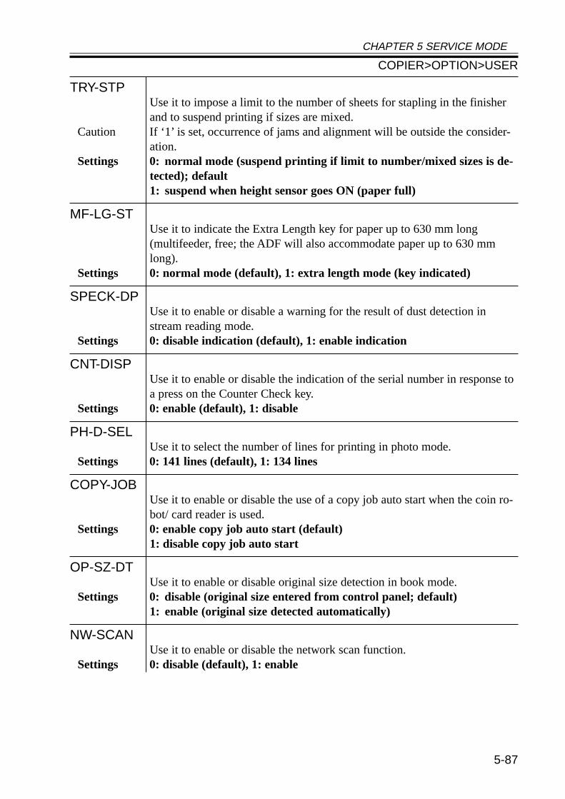
CHAPTER 5 SERVICE MODE
5-87
TRY-STPUse it to impose a limit to the number of sheets for stapling in the finisherand to suspend printing if sizes are mixed.
Caution If ‘1’ is set, occurrence of jams and alignment will be outside the consider-ation.
Settings 0: normal mode (suspend printing if limit to number/mixed sizes is de-tected); default1: suspend when height sensor goes ON (paper full)
MF-LG-STUse it to indicate the Extra Length key for paper up to 630 mm long(multifeeder, free; the ADF will also accommodate paper up to 630 mmlong).
Settings 0: normal mode (default), 1: extra length mode (key indicated)
SPECK-DPUse it to enable or disable a warning for the result of dust detection instream reading mode.
Settings 0: disable indication (default), 1: enable indication
CNT-DISPUse it to enable or disable the indication of the serial number in response toa press on the Counter Check key.
Settings 0: enable (default), 1: disable
PH-D-SELUse it to select the number of lines for printing in photo mode.
Settings 0: 141 lines (default), 1: 134 lines
COPY-JOBUse it to enable or disable the use of a copy job auto start when the coin ro-bot/ card reader is used.
Settings 0: enable copy job auto start (default)1: disable copy job auto start
OP-SZ-DTUse it to enable or disable original size detection in book mode.
Settings 0: disable (original size entered from control panel; default)1: enable (original size detected automatically)
NW-SCANUse it to enable or disable the network scan function.
Settings 0: disable (default), 1: enable
COPIER>OPTION>USER
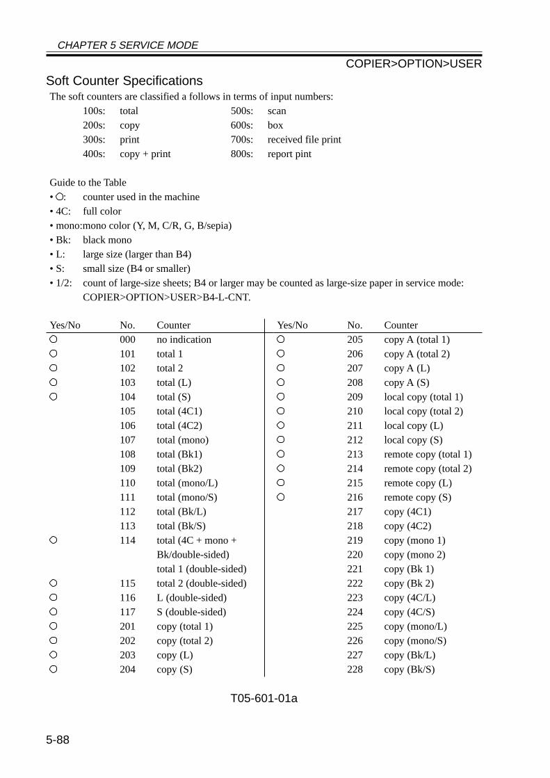
CHAPTER 5 SERVICE MODE
5-88
Soft Counter SpecificationsThe soft counters are classified a follows in terms of input numbers:
100s: total 500s: scan200s: copy 600s: box300s: print 700s: received file print400s: copy + print 800s: report pint
Guide to the Table• : counter used in the machine• 4C: full color• mono:mono color (Y, M, C/R, G, B/sepia)• Bk: black mono• L: large size (larger than B4)• S: small size (B4 or smaller)• 1/2: count of large-size sheets; B4 or larger may be counted as large-size paper in service mode:
COPIER>OPTION>USER>B4-L-CNT.
T05-601-01a
Yes/No No. Counter000 no indication101 total 1102 total 2103 total (L)104 total (S)105 total (4C1)106 total (4C2)107 total (mono)108 total (Bk1)109 total (Bk2)110 total (mono/L)111 total (mono/S)112 total (Bk/L)113 total (Bk/S)114 total (4C + mono +
Bk/double-sided)total 1 (double-sided)
115 total 2 (double-sided)116 L (double-sided)117 S (double-sided)201 copy (total 1)202 copy (total 2)203 copy (L)204 copy (S)
Yes/No No. Counter205 copy A (total 1)206 copy A (total 2)207 copy A (L)208 copy A (S)209 local copy (total 1)210 local copy (total 2)211 local copy (L)212 local copy (S)213 remote copy (total 1)214 remote copy (total 2)215 remote copy (L)216 remote copy (S)217 copy (4C1)218 copy (4C2)219 copy (mono 1)220 copy (mono 2)221 copy (Bk 1)222 copy (Bk 2)223 copy (4C/L)224 copy (4C/S)225 copy (mono/L)226 copy (mono/S)227 copy (Bk/L)228 copy (Bk/S)
COPIER>OPTION>USER
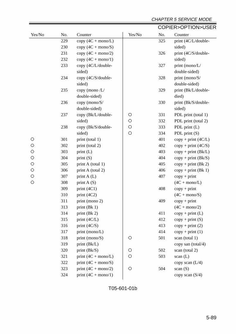
CHAPTER 5 SERVICE MODE
5-89
Yes/No No. Counter229 copy (4C + mono/L)230 copy (4C + mono/S)231 copy (4C + mono/2)232 copy (4C + mono/1)233 copy (4C/L/double-
sided)234 copy (4C/S/double-
sided)235 copy (mono /L/
double-sided)236 copy (mono/S/
double-sided)237 copy (Bk/L/double-
sided)238 copy (Bk/S/double-
sided)301 print (total 1)302 print (total 2)303 print (L)304 print (S)305 print A (total 1)306 print A (total 2)307 print A (L)308 print A (S)309 print (4C1)310 print (4C2)311 print (mono 2)313 print (Bk 1)314 print (Bk 2)315 print (4C/L)316 print (4C/S)317 print (mono/L)318 print (mono/S)319 print (Bk/L)320 print (Bk/S)321 print (4C + mono/L)322 print (4C + mono/S)323 print (4C + mono/2)324 print (4C + mono/1)
Yes/No No. Counter325 print (4C/L/double-
sided)326 print (4C/S/double-
sided)327 print (mono/L/
double-sided)328 print (mono/S/
double-sided)329 print (Bk/L/double-
died)330 print (Bk/S/double-
sided)331 PDL print (total 1)332 PDL print (total 2)333 PDL print (L)334 PDL print (S)401 copy + print (4C/L)402 copy + print (4C/S)403 copy + print (Bk/L)404 copy + print (Bk/S)405 copy + print (Bk 2)406 copy + print (Bk 1)407 copy + print
(4C + mono/L)408 copy + print
(4C + mono/S)409 copy + print
(4C + mono/2)411 copy + print (L)412 copy + print (S)413 copy + print (2)414 copy + print (1)501 scan (total 1)
copy san (total/4)502 scan (total 2)503 scan (L)
copy scan (L/4)504 scan (S)
copy scan (S/4)
T05-601-01b
COPIER>OPTION>USER
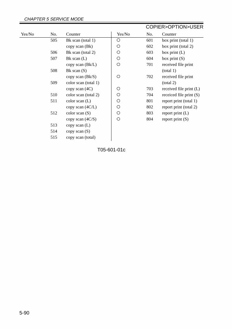
CHAPTER 5 SERVICE MODE
5-90
Yes/No No. Counter505 Bk scan (total 1)
copy scan (Bk)506 Bk scan (total 2)507 Bk scan (L)
copy scan (Bk/L)508 Bk scan (S)
copy scan (Bk/S)509 color scan (total 1)
copy scan (4C)510 color scan (total 2)511 color scan (L)
copy scan (4C/L)512 color scan (S)
copy scan (4C/S)513 copy scan (L)514 copy scan (S)515 copy scan (total)
Yes/No No. Counter601 box print (total 1)602 box print (total 2)603 box print (L)604 box print (S)701 received file print
(total 1)702 received file print
(total 2)703 received file print (L)704 receiced file print (S)801 report print (total 1)802 report print (total 2)803 report print (L)804 report print (S)
T05-601-01c
COPIER>OPTION>USER
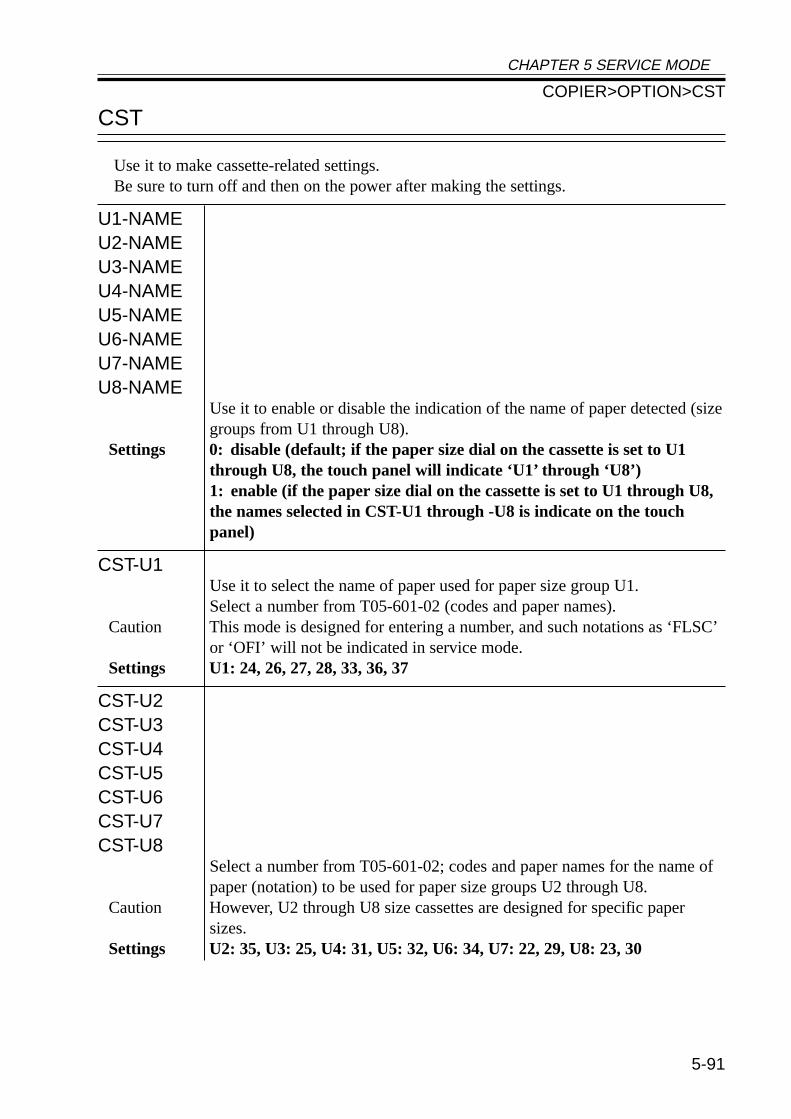
CHAPTER 5 SERVICE MODE
5-91
CST
Use it to make cassette-related settings.Be sure to turn off and then on the power after making the settings.
U1-NAMEU2-NAMEU3-NAMEU4-NAMEU5-NAMEU6-NAMEU7-NAMEU8-NAME
Use it to enable or disable the indication of the name of paper detected (sizegroups from U1 through U8).
Settings 0: disable (default; if the paper size dial on the cassette is set to U1through U8, the touch panel will indicate ‘U1’ through ‘U8’)1: enable (if the paper size dial on the cassette is set to U1 through U8,the names selected in CST-U1 through -U8 is indicate on the touchpanel)
CST-U1Use it to select the name of paper used for paper size group U1.Select a number from T05-601-02 (codes and paper names).
Caution This mode is designed for entering a number, and such notations as ‘FLSC’or ‘OFI’ will not be indicated in service mode.
Settings U1: 24, 26, 27, 28, 33, 36, 37
CST-U2CST-U3CST-U4CST-U5CST-U6CST-U7CST-U8
Select a number from T05-601-02; codes and paper names for the name ofpaper (notation) to be used for paper size groups U2 through U8.
Caution However, U2 through U8 size cassettes are designed for specific papersizes.
Settings U2: 35, U3: 25, U4: 31, U5: 32, U6: 34, U7: 22, 29, U8: 23, 30
COPIER>OPTION>CST
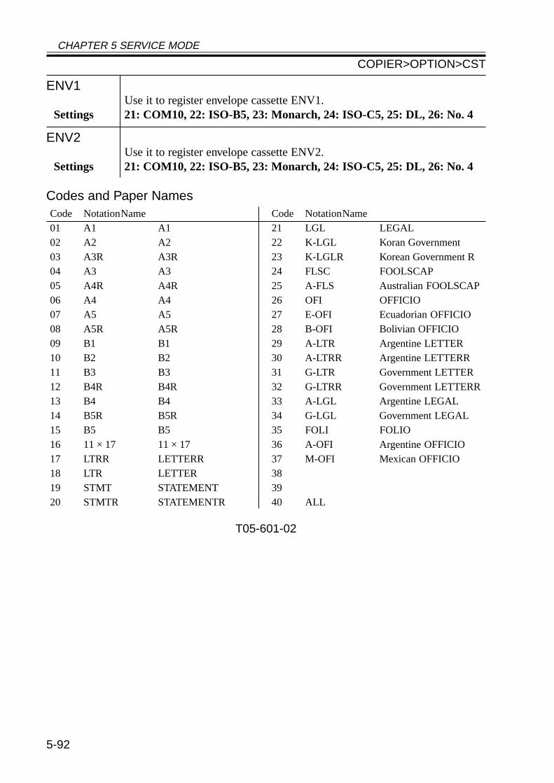
CHAPTER 5 SERVICE MODE
5-92
ENV1Use it to register envelope cassette ENV1.
Settings 21: COM10, 22: ISO-B5, 23: Monarch, 24: ISO-C5, 25: DL, 26: No. 4
ENV2Use it to register envelope cassette ENV2.
Settings 21: COM10, 22: ISO-B5, 23: Monarch, 24: ISO-C5, 25: DL, 26: No. 4
Codes and Paper Names
T05-601-02
Code NotationName01 A1 A102 A2 A203 A3R A3R04 A3 A305 A4R A4R06 A4 A407 A5 A508 A5R A5R09 B1 B110 B2 B211 B3 B312 B4R B4R13 B4 B414 B5R B5R15 B5 B516 11 × 17 11 × 1717 LTRR LETTERR18 LTR LETTER19 STMT STATEMENT20 STMTR STATEMENTR
Code NotationName21 LGL LEGAL22 K-LGL Koran Government23 K-LGLR Korean Government R24 FLSC FOOLSCAP25 A-FLS Australian FOOLSCAP26 OFI OFFICIO27 E-OFI Ecuadorian OFFICIO28 B-OFI Bolivian OFFICIO29 A-LTR Argentine LETTER30 A-LTRR Argentine LETTERR31 G-LTR Government LETTER32 G-LTRR Government LETTERR33 A-LGL Argentine LEGAL34 G-LGL Government LEGAL35 FOLI FOLIO36 A-OFI Argentine OFFICIO37 M-OFI Mexican OFFICIO383940 ALL
COPIER>OPTION>CST
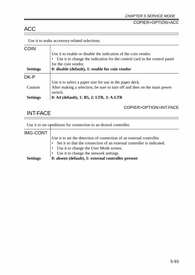
CHAPTER 5 SERVICE MODE
5-93
ACC
Use it to make accessory-related selections.
COINUse it to enable or disable the indication of the coin vendor.• Use it to change the indication for the control card in the control panelfor the coin vendor.
Settings 0: disable (default), 1: enable for coin vendor
DK-PUse it to select a paper size for use in the paper deck.
Caution After making a selection, be sure to turn off and then on the main powerswitch.
Settings 0: A4 (default), 1: B5, 2: LTR, 3: A-LTR
COPIER>OPTION>INT-FACE
INT-FACE
Use it to set conditions for connection to an dextral controller.
IMG-CONTUse it to set the detection of connection of an external controller.• Set it so that the connection of an external controller is indicated.• Use it to change the User Mode screen.• Use it to change the network settings.
Settings 0: absent (default), 1: external controller present
COPIER>OPTION>ACC
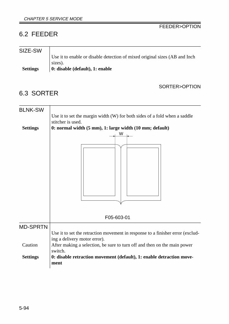
CHAPTER 5 SERVICE MODE
5-94
6.2 FEEDER
SIZE-SWUse it to enable or disable detection of mixed original sizes (AB and Inchsizes).
Settings 0: disable (default), 1: enable
SORTER>OPTION
6.3 SORTER
BLNK-SWUse it to set the margin width (W) for both sides of a fold when a saddlestitcher is used.
Settings 0: normal width (5 mm), 1: large width (10 mm; default)
F05-603-01
MD-SPRTNUse it to set the retraction movement in response to a finisher error (exclud-ing a delivery motor error).
Caution After making a selection, be sure to turn off and then on the main powerswitch.
Settings 0: disable retraction movement (default), 1: enable detraction move-ment
W
FEEDER>OPTION
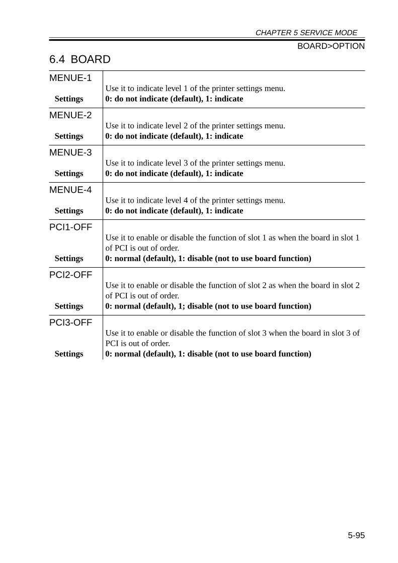
CHAPTER 5 SERVICE MODE
5-95
6.4 BOARD
MENUE-1Use it to indicate level 1 of the printer settings menu.
Settings 0: do not indicate (default), 1: indicate
MENUE-2Use it to indicate level 2 of the printer settings menu.
Settings 0: do not indicate (default), 1: indicate
MENUE-3Use it to indicate level 3 of the printer settings menu.
Settings 0: do not indicate (default), 1: indicate
MENUE-4Use it to indicate level 4 of the printer settings menu.
Settings 0: do not indicate (default), 1: indicate
PCI1-OFFUse it to enable or disable the function of slot 1 as when the board in slot 1of PCI is out of order.
Settings 0: normal (default), 1: disable (not to use board function)
PCI2-OFFUse it to enable or disable the function of slot 2 as when the board in slot 2of PCI is out of order.
Settings 0: normal (default), 1; disable (not to use board function)
PCI3-OFFUse it to enable or disable the function of slot 3 when the board in slot 3 ofPCI is out of order.
Settings 0: normal (default), 1: disable (not to use board function)
BOARD>OPTION
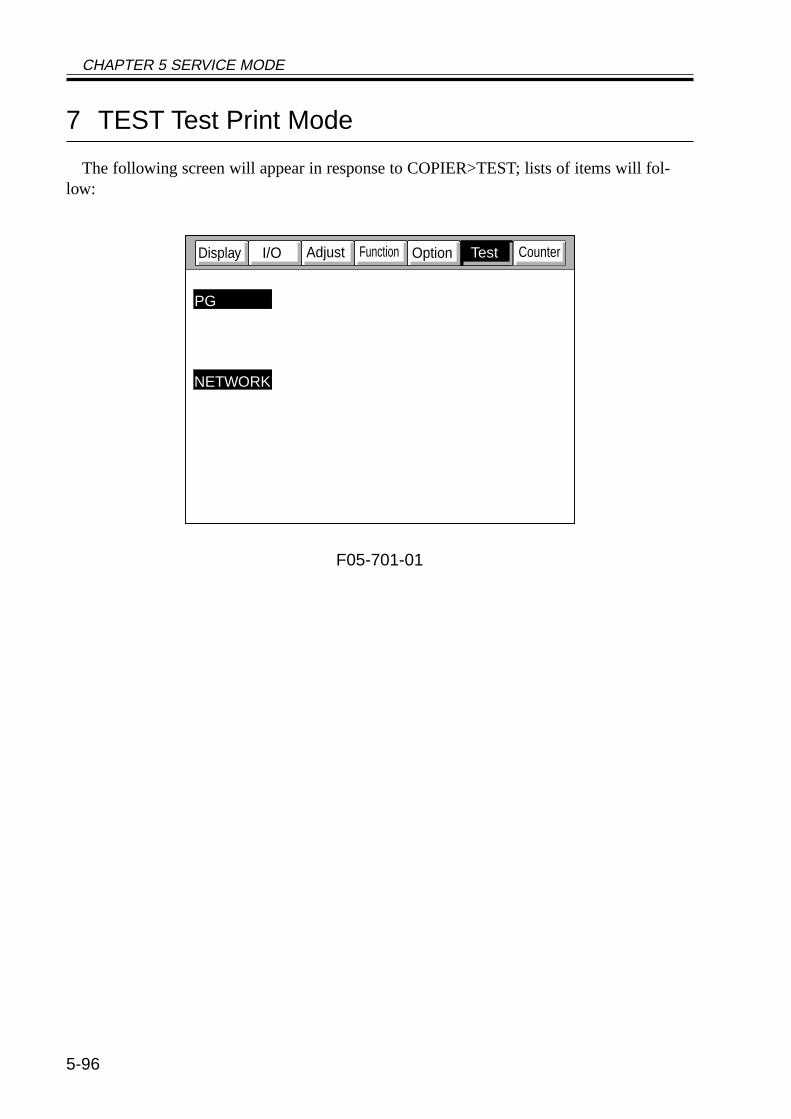
CHAPTER 5 SERVICE MODE
5-96
7 TEST Test Print Mode
The following screen will appear in response to COPIER>TEST; lists of items will fol-low:
F05-701-01
CounterFunctionAdjustI/ODisplay
PG
NETWORK
Option Test
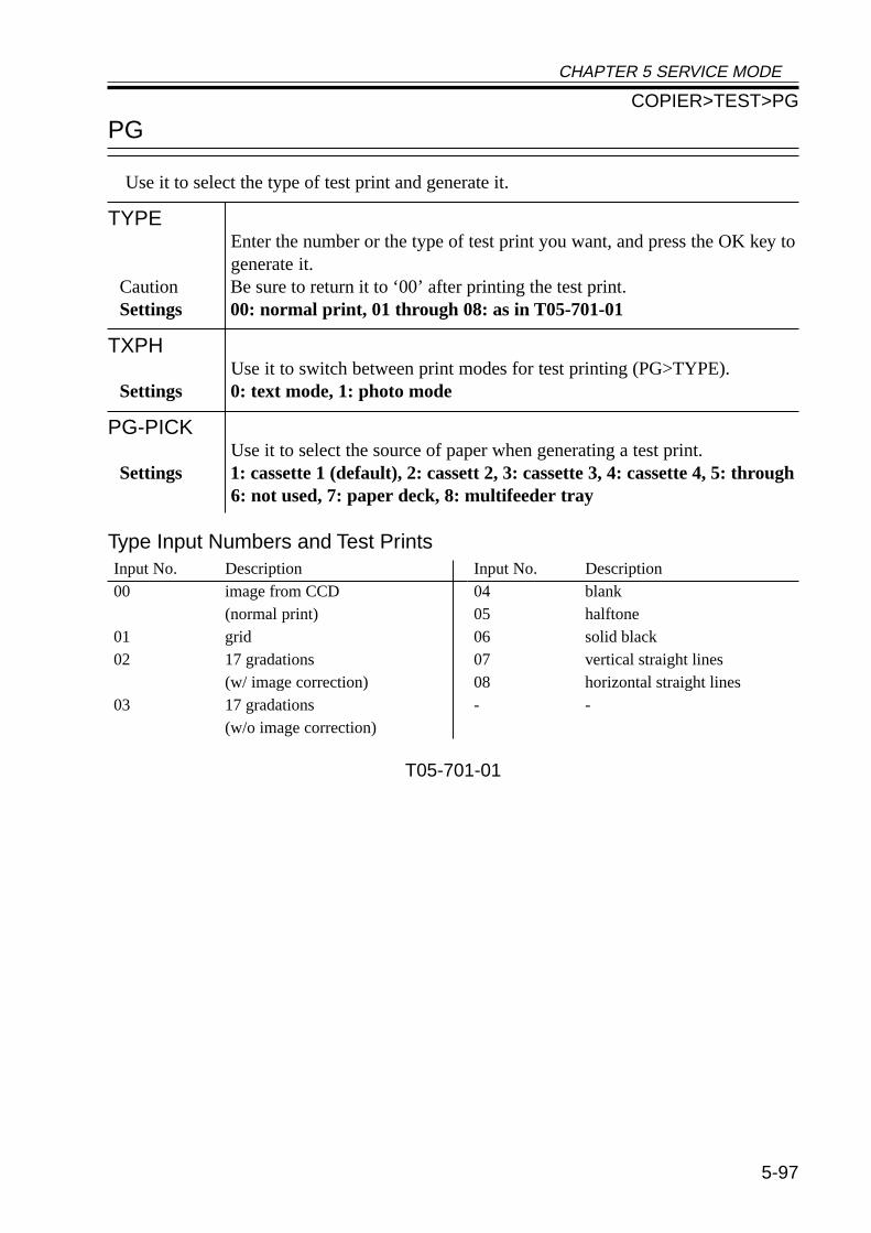
CHAPTER 5 SERVICE MODE
5-97
PG
Use it to select the type of test print and generate it.
TYPEEnter the number or the type of test print you want, and press the OK key togenerate it.
Caution Be sure to return it to ‘00’ after printing the test print.Settings 00: normal print, 01 through 08: as in T05-701-01
TXPHUse it to switch between print modes for test printing (PG>TYPE).
Settings 0: text mode, 1: photo mode
PG-PICKUse it to select the source of paper when generating a test print.
Settings 1: cassette 1 (default), 2: cassett 2, 3: cassette 3, 4: cassette 4, 5: through6: not used, 7: paper deck, 8: multifeeder tray
Type Input Numbers and Test Prints
T05-701-01
Input No. Description00 image from CCD
(normal print)01 grid02 17 gradations
(w/ image correction)03 17 gradations
(w/o image correction)
Input No. Description04 blank05 halftone06 solid black07 vertical straight lines08 horizontal straight lines- -
COPIER>TEST>PG
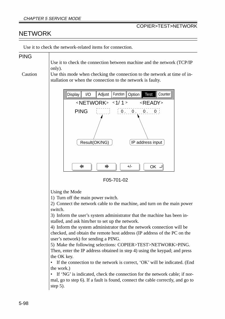
CHAPTER 5 SERVICE MODE
5-98
NETWORK
Use it to check the network-related items for connection.
PINGUse it to check the connection between machine and the network (TCP/IPonly).
Caution Use this mode when checking the connection to the network at time of in-stallation or when the connection to the network is faulty.
F05-701-02
Using the Mode1) Turn off the main power switch.2) Connect the network cable to the machine, and turn on the main powerswitch.3) Inform the user’s system administrator that the machine has been in-stalled, and ask him/her to set up the network.4) Inform the system administrator that the network connection will bechecked, and obtain the remote host address (IP address of the PC on theuser’s network) for sending a PING.5) Make the following selections: COPIER>TEST>NETWORK>PING.Then, enter the IP address obtained in step 4) using the keypad; and pressthe OK key.• If the connection to the network is correct, ‘OK’ will be indicated. (Endthe work.)• If ‘NG’ is indicated, check the connection for the network cable; if nor-mal, go to step 6). If a fault is found, connect the cable correctly, and go tostep 5).
CounterOptionFunctionI/O
NETWORK 1/ 1 READY< > < > < >
+/- OK
Display Adjust
Result(OK/NG)
PING
IP address input
0 . 0 . 0 . 0
Test
COPIER>TEST>NETWORK
CHAPTER 5 SERVICE MODE
5-99
6) Make the following selections : COPIER>TEST>NETWORK>PING.Then, enter the loop-back address* (127.0.0.1), and press the OK key andthen the Start key.• If ‘NG’ is indicated, suspect a fault in the TCP/IP settings of the ma-chine. Go back to step 3), and check the settings once again.• If ‘OK’ is indicated, the TCP/IP setting may be assumed to be free of aproblem. However, the connection of the network interface board (NIC) orthe board itself may have a fault. Go to step 7).*The loop-back address is returned in front of the NIC and, therefore, it en-ables a check on the TCP/IP settings of the machine.7) Make the following selections in service mode:COPIER>TEST>NETWORK>PING. Then, press the OK key.• If ‘NG’ is indicated, suspect a fault in the connection of the NIC or in theNIC itself. Check the connection of the NIC or replace it.• If ‘OK is indicated, the network setting of the machine and the NIC maybe assumed to be free of a fault.In this case, the user’s network may have a problem. Report to the systemadministrator for corrective action.
COPIER>TEST>NETWORK
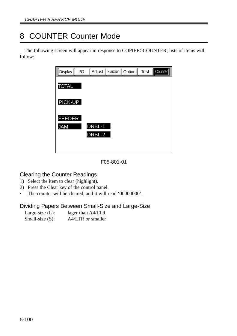
CHAPTER 5 SERVICE MODE
5-100
8 COUNTER Counter Mode
The following screen will appear in response to COPIER>COUNTER; lists of items willfollow:
F05-801-01
Clearing the Counter Readings1) Select the item to clear (highlight).2) Press the Clear key of the control panel.• The counter will be cleared, and it will read ‘00000000’.
Dividing Papers Between Small-Size and Large-SizeLarge-size (L): lager than A4/LTRSmall-size (S): A4/LTR or smaller
TestOptionI/ODisplay
PICK-UP
TOTAL
DRBL-1
DRBL-2
JAM
FEEDER
Adjust Function Counter
CHAPTER 5 SERVICE MODE
5-101
Guide to the Counters for Periodically Replaced Parts and DurablesThe machine is equipped with counters for periodically replaced parts and durables
(DRBL-1/DRBL-2) so as to provide an idea of when to replace the parts.A small-size sheet increments the counter reading by ‘1’, while a large-size sheet incre-
ments the count by ‘2’.
EX.TR-ROOL / 00000201 / 00240000 / 0% !! 000082
[1] [2] [3] [4] [5] [6][1] indicates the name of the part; in the case of the example, the transfer charging roller.[2] indicates the counter reading (actual number of sheets; be sure to clear the reading after
replacing the part).[3] indicates the limit (number of sheets before replacement); to change, select the item, and
enter a number using the keypad, and then press the OK key.[4] indicates the relationship between the counter reading and the limit.[5] indicates a single exclamation mark (!) for a ratio between 90% and 100%, two marks
for 100% and higher; in the case of the example, no indication is made.[6] indicates the number of days to the estimated time of replacement; the example shows
82 days.
List of COUNTER ItemsLevel 1: COUNETR Mode description
Level 2: TOTALLevel 3: SERVICE1 total counter 1 for service
SERVICE2 total counter 2 for serviceCOPY copy counterPDL-PRT PDL print counterFAX-PRT fax received file print counterRMT-PRT remote copy/print counterBOX-PRT Box print counterRPT-PRT repro print counter2-SIDE double-sided print counterSCAN scan counter
COPIER>COUNTER>TOTAL
CHAPTER 5 SERVICE MODE
5-102
Level 2: PICK-UPLevel 3: C1 cassette 1 pickup counter
C2 cassette 2 pickup counterC3 cassette 3 pickup counterC4 cassette 4 pickup counterMF multifeeder tray pickup counterDK paper deck pickup counter2-SIDE double-sided 2nd side pickup counter
COPIER>COUNTER>FEEDERLevel 2: FEEDER
Level 3: FEED feeder(ADF) pickup total counter
COPIER>COUNTER>JAMLevel 2: JAM
Level 3: TOTAL machine total jam counterFEEDER feeder (ADF) jam counterSORTER sorter (finisher) jam counter2-SIDE duplex unit jam counterMF multifeeder tray jam counterC1 cassette 1 jam counterC2 cassette 2 jam counterC3 cassette 3 jam counterC4 cassette 4 jam counterDK paper deck jam counter
COPIER>COUNTER>PICK-UP
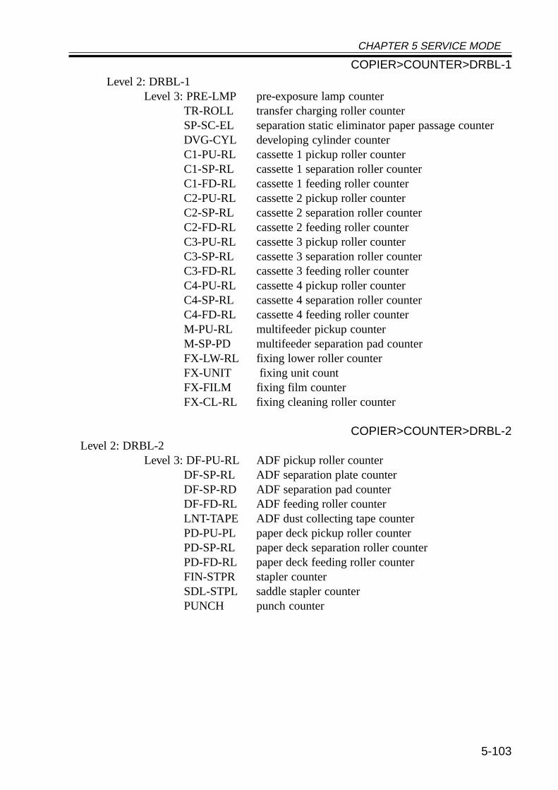
CHAPTER 5 SERVICE MODE
5-103
Level 2: DRBL-1Level 3: PRE-LMP pre-exposure lamp counter
TR-ROLL transfer charging roller counterSP-SC-EL separation static eliminator paper passage counterDVG-CYL developing cylinder counterC1-PU-RL cassette 1 pickup roller counterC1-SP-RL cassette 1 separation roller counterC1-FD-RL cassette 1 feeding roller counterC2-PU-RL cassette 2 pickup roller counterC2-SP-RL cassette 2 separation roller counterC2-FD-RL cassette 2 feeding roller counterC3-PU-RL cassette 3 pickup roller counterC3-SP-RL cassette 3 separation roller counterC3-FD-RL cassette 3 feeding roller counterC4-PU-RL cassette 4 pickup roller counterC4-SP-RL cassette 4 separation roller counterC4-FD-RL cassette 4 feeding roller counterM-PU-RL multifeeder pickup counterM-SP-PD multifeeder separation pad counterFX-LW-RL fixing lower roller counterFX-UNIT fixing unit countFX-FILM fixing film counterFX-CL-RL fixing cleaning roller counter
COPIER>COUNTER>DRBL-2Level 2: DRBL-2
Level 3: DF-PU-RL ADF pickup roller counterDF-SP-RL ADF separation plate counterDF-SP-RD ADF separation pad counterDF-FD-RL ADF feeding roller counterLNT-TAPE ADF dust collecting tape counterPD-PU-PL paper deck pickup roller counterPD-SP-RL paper deck separation roller counterPD-FD-RL paper deck feeding roller counterFIN-STPR stapler counterSDL-STPL saddle stapler counterPUNCH punch counter
COPIER>COUNTER>DRBL-1


CHAPTER 6 SELF DIAGNOSIS
6-1
CHAPTER 6 SELF DIAGNOSIS
1 Self Diagnosis
The machine is equipped with a mechanism that checks the condition of the machine (es-pecially sensor outputs) and indicates an error code in the control panel upon detection of afault.
The following tables show the codes used, timing of detection, and possible causes; a 4-digit code is a detail code, and may be checked in service mode (COPIER>DISPLAY>JAM/ERR).
6
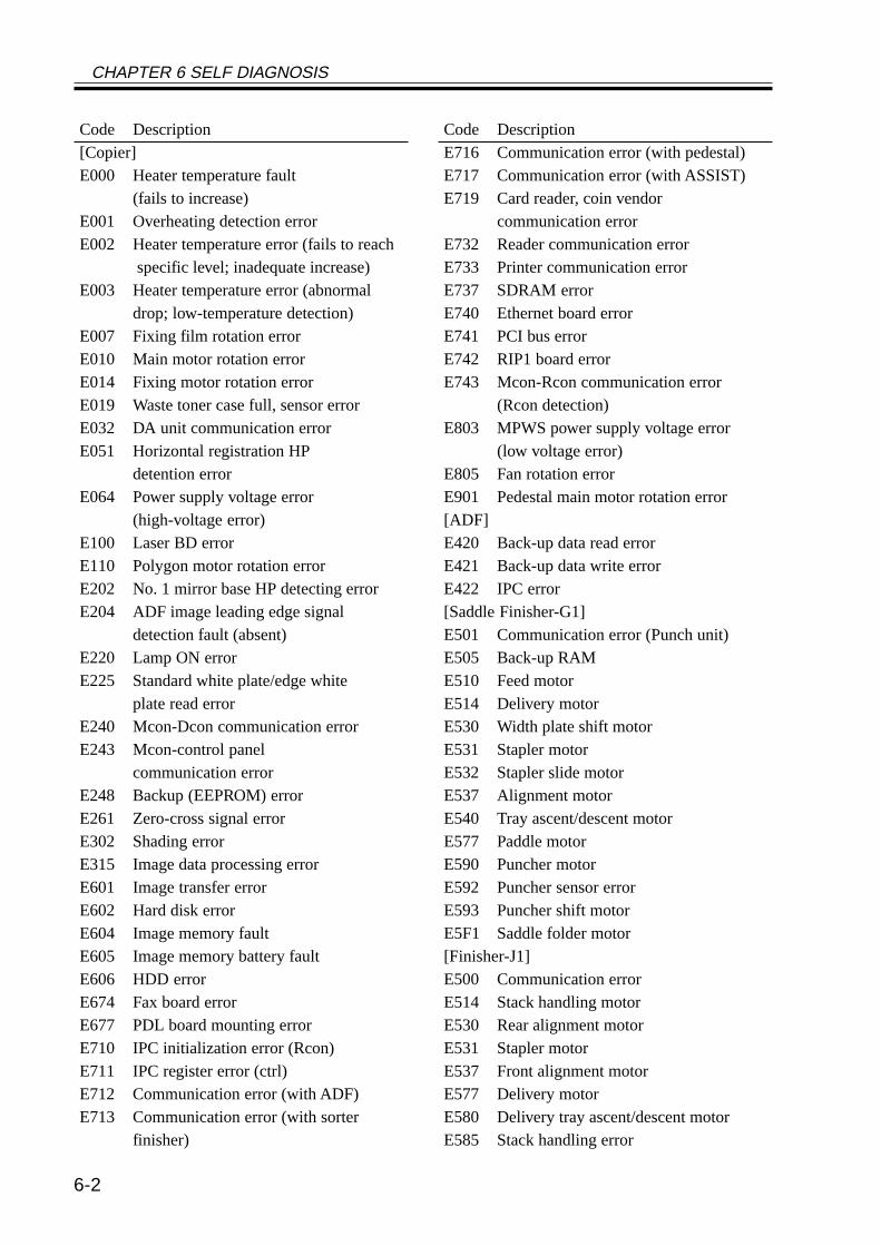
CHAPTER 6 SELF DIAGNOSIS
6-2
Code DescriptionE716 Communication error (with pedestal)E717 Communication error (with ASSIST)E719 Card reader, coin vendor
communication errorE732 Reader communication errorE733 Printer communication errorE737 SDRAM errorE740 Ethernet board errorE741 PCI bus errorE742 RIP1 board errorE743 Mcon-Rcon communication error
(Rcon detection)E803 MPWS power supply voltage error
(low voltage error)E805 Fan rotation errorE901 Pedestal main motor rotation error[ADF]E420 Back-up data read errorE421 Back-up data write errorE422 IPC error[Saddle Finisher-G1]E501 Communication error (Punch unit)E505 Back-up RAME510 Feed motorE514 Delivery motorE530 Width plate shift motorE531 Stapler motorE532 Stapler slide motorE537 Alignment motorE540 Tray ascent/descent motorE577 Paddle motorE590 Puncher motorE592 Puncher sensor errorE593 Puncher shift motorE5F1 Saddle folder motor[Finisher-J1]E500 Communication errorE514 Stack handling motorE530 Rear alignment motorE531 Stapler motorE537 Front alignment motorE577 Delivery motorE580 Delivery tray ascent/descent motorE585 Stack handling error
Code Description[Copier]E000 Heater temperature fault
(fails to increase)E001 Overheating detection errorE002 Heater temperature error (fails to reach
specific level; inadequate increase)E003 Heater temperature error (abnormal
drop; low-temperature detection)E007 Fixing film rotation errorE010 Main motor rotation errorE014 Fixing motor rotation errorE019 Waste toner case full, sensor errorE032 DA unit communication errorE051 Horizontal registration HP
detention errorE064 Power supply voltage error
(high-voltage error)E100 Laser BD errorE110 Polygon motor rotation errorE202 No. 1 mirror base HP detecting errorE204 ADF image leading edge signal
detection fault (absent)E220 Lamp ON errorE225 Standard white plate/edge white
plate read errorE240 Mcon-Dcon communication errorE243 Mcon-control panel
communication errorE248 Backup (EEPROM) errorE261 Zero-cross signal errorE302 Shading errorE315 Image data processing errorE601 Image transfer errorE602 Hard disk errorE604 Image memory faultE605 Image memory battery faultE606 HDD errorE674 Fax board errorE677 PDL board mounting errorE710 IPC initialization error (Rcon)E711 IPC register error (ctrl)E712 Communication error (with ADF)E713 Communication error (with sorter
finisher)
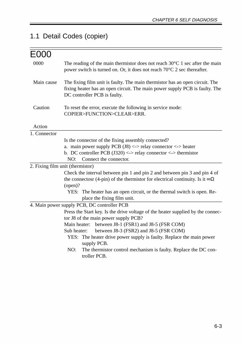
CHAPTER 6 SELF DIAGNOSIS
6-3
1.1 Detail Codes (copier)
E0000000 The reading of the main thermistor does not reach 30°C 1 sec after the main
power switch is turned on. Or, it does not reach 70°C 2 sec thereafter.
Main cause The fixing film unit is faulty. The main thermistor has an open circuit. Thefixing heater has an open circuit. The main power supply PCB is faulty. TheDC controller PCB is faulty.
Caution To reset the error, execute the following in service mode:COPIER>FUNCTION>CLEAR>ERR.
Action1. Connector
Is the connector of the fixing assembly connected?a. main power supply PCB (J8) <-> relay connector <-> heaterb. DC controller PCB (J320) <-> relay connector <-> thermistor
NO: Connect the connector.2. Fixing film unit (thermistor)
Check the interval between pin 1 and pin 2 and between pin 3 and pin 4 ofthe connectosr (4-pin) of the thermistor for electrical continuity. Is it ∞Ω(open)?
YES: The heater has an open circuit, or the thermal switch is open. Re-place the fixing film unit.
4. Main power supply PCB, DC controller PCBPress the Start key. Is the drive voltage of the heater supplied by the connec-tor J8 of the main power supply PCB?Main heater: between J8-1 (FSR1) and J8-5 (FSR COM)Sub heater: between J8-3 (FSR2) and J8-5 (FSR COM)
YES: The heater drive power supply is faulty. Replace the main powersupply PCB.
NO: The thermistor control mechanism is faulty. Replace the DC con-troller PCB.
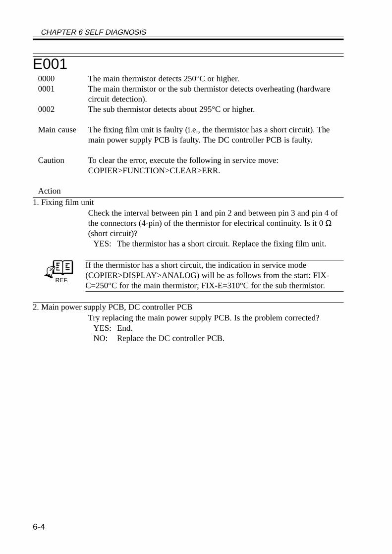
CHAPTER 6 SELF DIAGNOSIS
6-4
E0010000 The main thermistor detects 250°C or higher.0001 The main thermistor or the sub thermistor detects overheating (hardware
circuit detection).0002 The sub thermistor detects about 295°C or higher.
Main cause The fixing film unit is faulty (i.e., the thermistor has a short circuit). Themain power supply PCB is faulty. The DC controller PCB is faulty.
Caution To clear the error, execute the following in service move:COPIER>FUNCTION>CLEAR>ERR.
Action1. Fixing film unit
Check the interval between pin 1 and pin 2 and between pin 3 and pin 4 ofthe connectors (4-pin) of the thermistor for electrical continuity. Is it 0 Ω(short circuit)?
YES: The thermistor has a short circuit. Replace the fixing film unit.
REF.
If the thermistor has a short circuit, the indication in service mode(COPIER>DISPLAY>ANALOG) will be as follows from the start: FIX-C=250°C for the main thermistor; FIX-E=310°C for the sub thermistor.
2. Main power supply PCB, DC controller PCBTry replacing the main power supply PCB. Is the problem corrected?
YES: End.NO: Replace the DC controller PCB.
CHAPTER 6 SELF DIAGNOSIS
6-5
E0020000 The temperature of the fixing film is as follows:
1. has exceeded 100°C, but does not reach 115°C within 1 sec thereafter.2. has exceeded 140°C, but does not reach 150°C within 1 sec thereafter.3. has exceeded 160°C, but does not reach 165°C within 1 sec thereafter.
Main cause The fixing film unit is faulty (i.e., the main thermistor TH1 has poor con-tact, or the fixing heater is faulty). The main power supply PCB is faulty.The DC controller PCB is faulty.
Caution To clear the error, execute the following in service mode:COPIER>FUNCTION>FCLEAR>ERR.
Action See the description for E003.
E0030000 The main thermistor reading is lower than 140°C when paper is moved.
Main cause The fixing film unit is faulty (i.e., the main thermistor (TH1) has poor con-tact or has an open circuit; or, the fixing heater is faulty). The main powersupply PCB is faulty. The DC controller PCB is faulty.
Caution To clear the error, execute the following in service mode:COPIER>FUNCTION>CLEAR>ERR.
Action1. State
Turn on the power switch, and clear E002/E003. Thereafter, turn off andthen on the power switch. Does the fixing heater operate?
NO: See “The fixing heater fails to operate.”2. Wiring
Is the wiring from the DC controller PCB to the fixing film unit normal?NO: Correct the wiring.
3. Fixing film unit, DC controller PCBTry replacing the fixing film unit. Is the problem corrected?
YES: End.NO: Replace the DC controller PCB.
CHAPTER 6 SELF DIAGNOSIS
6-6
E0070000 An error in the rotation of the fixing film is detected.
The reading of the main thermistor is 100°C or higher and, in addition, thefixing film sensor does not detect the rotation of the film for 6 sec or morewhile the fixing motor is driven.
Main cause The fixing film sensor (PS45) is faulty. The DC controller PCB is faulty.
Caution To clear the error, execute the following in service mode:COPIER>FUNCTION>CLEAR>ERR.
Action1. Wiring
Are the wring and the connectors connected securely?DC controller PCB (J311) <-> relay connector <-> fixing film sensor
NO: Connect the wiring and the connectors.2. Fixing film sensor
Check the fixing film rotation signal.When the fixing motor is rotating, isthe film rotation detection signal sent by the fixing film sensor to theconcoctor J311 of the DC controller PCB?Film rotation detection signal: 5V pulse signal between J311-A9(FILM_ROT_D) and J311-A8 (GND); at intervals of 100 msec ON and 440msec OFF
NO: If the fixing film is normal, replace the sensor.3. Fixing film unit, DC controller PCB
Is there a fault in the fixing film edge rotation detection mechanism?YES: Replace the fixing film unit.NO: Replace the DC controller PCB.
CHAPTER 6 SELF DIAGNOSIS
6-7
E0100000 After the main motor drive signal is generated, the clock signal does to ar-
rive within 1.3 sec.
Main cause The main motor (M2) is faulty. the DC controller PCB is faulty.
Action1. Connector
Is the connector of the main motor connected?NO: Connect the connector.
2. Main power supply PCBIs the drive voltage (24 V) of the main motor supplied by the main powersupply PCB?Main power supply PCB: between J202-1 (24VU1-SW) and J202-2(OVU1)
NO: Replace the main power supply PCB.3. Main motor (M2), DC controller PCB
Press the Start key. Is the lock signal of the main motor present at the con-nector J308 on the DC controller PCB?Lock signal: J318-A10 (MM_LOCK)
YES: Replace the main motor.NO: Check the wiring; if normal, replace the DC controller PCB.
CHAPTER 6 SELF DIAGNOSIS
6-8
E014000 After the fixing motor drive signal is generated, the clock signal does not
arrive within 1.3 sec.
Main cause The fixing motor (M19) is faulty. The DC controller PCB is faulty.
Action1. Connector
Is the connector of the fixing motor connected?NO: Connect the connector.
2. Main power supply PCBIs the drive voltage (24 V) of the fixing motor supplied by the main powersupply PCB?Main power supply PCB: between J202-3 (24VU1-S) and J202-4 (OVU1)
NO: Replace the main power supply PCB.3. Fixing motor (M19), DC controller PCB
Press the Start key. Is the lock signal of the fixing motor present at the con-nector (J312) on the DC controller PCB?Lock signal: J312-B4 (FSRM_LOCK*)the DC controller PCB change from 0 to about 5 V?
YES: Replace the fixing motor.NO: Replace the DC controller PCB.
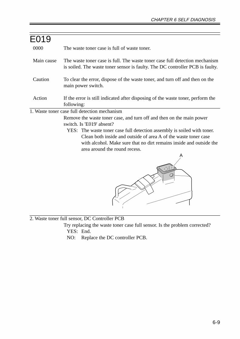
CHAPTER 6 SELF DIAGNOSIS
6-9
E0190000 The waste toner case is full of waste toner.
Main cause The waste toner case is full. The waste toner case full detection mechanismis soiled. The waste toner sensor is faulty. The DC controller PCB is faulty.
Caution To clear the error, dispose of the waste toner, and turn off and then on themain power switch.
Action If the error is still indicated after disposing of the waste toner, perform thefollowing:
1. Waste toner case full detection mechanismRemove the waste toner case, and turn off and then on the main powerswitch. Is 'E019' absent?
YES: The waste toner case full detection assembly is soiled with toner.Clean both inside and outside of area A of the waste toner casewith alcohol. Make sure that no dirt remains inside and outside thearea around the round recess.
2. Waste toner full sensor, DC Controller PCBTry replacing the waste toner case full sensor. Is the problem corrected?
YES: End.NO: Replace the DC controller PCB.
A
CHAPTER 6 SELF DIAGNOSIS
6-10
E0320001 The DA unit connection is disconnected (after connection).
Main cause The DA unit is faulty. The main controller PCB is faulty.
Action1. Connector
Is the DA unit connected securely?NO: Connect it securely.
2. DA controller, Main controller PCBTry replacing the DA unit. Is the problem corrected?
YES: End.NO: Replace the main controller PCB.
CHAPTER 6 SELF DIAGNOSIS
6-11
E0510000 At start-up, home position is not detected when the horizontal registration
assembly is moved 100 mm in the direction of home position.
Main cause The horizontal home position sensor is faulty. The horizontal registrationmotor is faulty. The DC controller PCB is faulty.
Action1. Connector
Are the connectors of the horizontal registration home position sensor andthe horizontal registration motor connected?a. DC controller PCB (J304) <-> relay connector <-> horizontal registra-tion home position sensorb. DC controller PCB (J304) <-> relay connector <-> horizontal registra-tion motor
NO: Connect the connectors.2. Sensor lever (damage and interference), Sensor
Is abnormal noise heard from the horizontal registration assembly in keep-ing with the motor rotation?
YES: a. The horizontal registration assembly is out of place because ofdamage to the sensor lever. Replace the sensor lever.b. The horizontal registration assembly malfunctions because of thepresence of foreign matter. Remove the foreign matter.c. The sensor is faulty and cannot detect home position. Replace thesensor.
3. Horizontal registration motor, DC controller PCBIs the horizontal registration motor control signal generated by the DC con-troller PCB?J304-1/2: 24 V, J304-3/4/5/6: motor excitation signal
YES: The horizontal registration motor is faulty. Replace the motor.NO: Replace the DC controller PCB.
CHAPTER 6 SELF DIAGNOSIS
6-12
E0640000 The presence of a high-voltage error is communicated by the composite
power supply PCB. (The output for primary charging, developing, or trans-fer has deviated from a specific level of voltage.)
Main cause The contact has poor connection. The wiring is faulty. The composite powersupply PCB is faulty. The DC controller PCB is faulty.
Action1. Contact
Is any of the contacts of the primary charging roller, developing assembly,or transfer charging roller soiled? Or, is there poor contact?
YES: Clean the contact, and set it once again.2. Wiring
Is the wiring between the contacts for the following normal: DC controllerPCB (J301), composite power supply PCB (J136), primary charging roller,developing assembly, transfer charging roller?a. DC controller PCB (J301) <-> composite power supply PCB (J136)b. composite power supply PCB (J130-7) <-> primary charging roller con-tactc. composite power supply PCB (J130-1) <-> developing assembly contactd. composite power supply PCB (FT133) <-> transfer roller contact
NO: Correct the connection.3. Composite power supply PCB, DC controller PCB
Try replacing the composite power supply PCB. Is the problem corrected?YES: Yes.NO: Replace the DC controller PCB.
CHAPTER 6 SELF DIAGNOSIS
6-13
E1000001 The BD signal is not detected 10 times or more within 10 msec in 5 msec
after the generation of the laser drive signal.0002 While the laser is ON, the BD signal cycle is outside a specific range 20
times or more continuously.0003 While the laser is ON, the horizontal sync signal cycle is outside a specific
range 20 times or more.
Main cause The wiring is faulty (short circuit, open circuit). The BD PCB is faulty. Thelaser scanner unit is faulty. The DC controller PCB is faulty.
Action1. BD PCB
Try replacing the BD PCB. Is the problem corrected?YES: End.
2. Laser scanner unit, DC controller PCBTry replacing the laser scanner unit. Is the problem corrected?
YES: End.NO: Replace the DC controller PCB.
CHAPTER 6 SELF DIAGNOSIS
6-14
E1100000 The motor ready signal does not arrive within 15 sec after the laser scanner
motor drive signal is generated.
Main cause The wiring is faulty (short circuit, open circuit, disconnection). The laserscanner motor (M10) is faulty. The main power supply PCB is faulty. TheDC controller PCB is faulty.
Action1. Connector
Are the connector (J312) on the DC controller PCB and the relay connectorconnected securely?
NO: Connect the connectors securely.2. Main power supply PCB
During printing, does the voltage between J204-1 (+) and J204-2 (-) on themain power supply PCB change from 0 to about 24 V?
NO: Replace the main power supply PCB.3. Laser scanner unit, DC controller PCB
Try replacing the laser scanner unit. Is the problem corrected?YES: End.NO: Replace the DC controller PCB.
CHAPTER 6 SELF DIAGNOSIS
6-15
E202The home position sensor does not go ON when the main power switch is turned on.0001 The scanner home position sensor does not go OFF when the scanner is
moved forward by 40 mm.0002 The scanner home position sensor does not go ON when the scanner is
moved reverse 450 mm.
Main cause The scanner home position sensor (PS400) is faulty. The scanner motor(M400) is faulty. The reader controller PCB is faulty.
Action1. State
Does the scanner operate when the power is turned on?NO: See 4.2.9 “The No. 1 mirror base does not operate.”
2. Scanner home position sensor (PS400), Reader controller PCBMove the No. 1 mirror base by hand from home position. Does the outputof the scanner home position sensor change? (J405-2 on the reader control-ler PCB is 5 V (in HP) or 0V (away from HP))
NO: Replace the sensor.YES: Replace the rear controller PCB.
E2040001 While an original is being read, the image leading edge signal does not ar-
rive from the ADF.
Main cause The ADF controller PCB is faulty. The reader controller PCB is faulty.
Caution When this code occurs, no code is indicated, but the keys are locked. Thecode may be checked in service mode: COPIER>DISPLAY>ERR.
Action1. Read sensor (S2)
Try replacing the read sensor of the ADF. Is the problem corrected?YES: End.
2. ADF controller PCB, Reader controller PCBTry replacing the ADF controller PCB. Is the problem corrected?
YES: End.NO: Replace the reader controller PCB.
CHAPTER 6 SELF DIAGNOSIS
6-16
E2200001 A fault is detected on the inverter PCB for the scanning lamp.
Main cause The inverter PCB is faulty. The reader controller PCB is faulty.
Action1. Wiring
Is the wiring from the scanning lamp to the reader controller PCB normal?NO: Connect the connector firmly, and correct or replace the wiring.
2. Inverter PCB, Reader controller PCBTry replacing the lamp inverter PCB. Is the problem corrected?
YES: End.NO: Replace the reader controller PCB.
E2250000 A specific level cannot be attained for the signal during CCD gain correc-
tion at power-on.0002 The edge gain correction level is different from the correction level for the
preceding sheet by a specific level or more.
Main cause The scanning lamp is faulty. The CCD PCB is faulty. The rear controllerPCB is faulty.
Action1. Scanning lamp (LAMP1)
Is the lamp ON during the initial operation after the main power switch isturned on?
NO: Replace the scanning lamp.2. CCD unit, Reader controller PCB
Try replacing the CCD unit. Is the problem corrected?YES: End.NO: Replace the reader controller PCB.
CHAPTER 6 SELF DIAGNOSIS
6-17
E2400000 A fault occurs in communication between the CPU of the main controller
PCB and the CPU of the DC controller PCB.
Main cause The main controller PCB is faulty. The DC controller PCB is faulty.
Action1. Wiring
Is the wiring from the min controller PCB to the DC controller PCB nor-mal?
NO: Correct the wiring.2. DC controller PCB, Main controlled PCB
Try replacing the DC controller PCB. Is the problem corrected?YES: End.NO: Replace the main controller PCB.
E2430000 A fault occurs in the communication between the CPU of the control panel
PCB and the CPU of the main controller PCB.
Main cause The control panel CPU PCB is faulty. The main controller PCB is faulty.
Action1. Wiring
Is the wiring from the main controller PCB to the DC controller PCB nor-mal?
NO: Correct the wiring.2. Control panel CPU PCB, Main controller PCB
Try replacing the control panel CPU PCB. Is the problem corrected?YES: End.NO: Replace the main controller PCB.
CHAPTER 6 SELF DIAGNOSIS
6-18
E2480001 A difference is discovered between the ID in EEPROM read when the main
power switch is turned on and the ID in ROM upon comparison.0002 The data read does not match the data written to EEPROM.0003 A difference is discovered between the ID of EEPROM and the ID of ROM
upon comparison while writing data.
Main cause The EEPROM (IC403) of the reader controller PCB is faulty. The readercontroller PCB is faulty.
Action1. Execute the following in service mode: COPIER>FUNCTION>CLEAR>CON. Is the
proem corrected?YES: End. After executing the service mode, be sure to enter the service
mode data newly.2. EE-PROM, Reader controller PCB
Try replacing the EE-PROM. Is the problem corrected?YES: End. After replacement, be sure to enter the service mode data
newly.NO: Replace the rear controller PCB. After replacement, be sure to en-
ter the service mode date newly.
E2610000 The intervals of zero-cross signals deviate from the tolerance range while
the fixing heater is supplied with power.
Main cause The wiring is faulty (short circuit, open circuit). The main power supplyPCB is faulty. The DC controller PCB is faulty.
Making Corrections1. Connectors
Are the connector J205 on the main power supply PCB and the connectorJ308B on the DC controller PCB securely connected? (zero-cross signal:J205-7 <-> J308B-1)
NO: Connect the connectors securely.2. Main power supply PCB, Main controller PCB
Try replacing the main power supply PCB. Is the problem corrected?YES: End.NO: Replace the DC controller PCB.
CHAPTER 6 SELF DIAGNOSIS
6-19
E3020001 During shading, the shading processing does not end on the reader control-
ler PCB after 1 sec.0002 During stream reading, the edge white addition processing does not end on
the rear controller PCB after 10 sec.
Main cause The CCD PCB is faulty. The wiring is faulty (short circuit, open circuit).The reader controller PCB is faulty.
Action1. Connector
Are the connectors (J6001/J6002) on the CCD PCB and the connectors(J5002/J5003) on the reader controller PCB connected securely?
NO: Connect the connectors securely.2. CCD unit
Try replacing the CCD unit. Is the problem corrected?YES: End.
3. Reader controller PCB, Main controller PCBTry replacing the reader controller PCB. Is the problem corrected?
YES: End.NO: Check the wiring; if normal, replace the main controller PCB.
CHAPTER 6 SELF DIAGNOSIS
6-20
E315Any of the following is true in the image processing by the main controller:1. The image data has a fault.2. The encoding/decoding operation for image data has a fault.3. The image processing element of the main controller PCB has a fault.
Main cause The image data is faulty. The main controller PCB is faulty. The HDD isfaulty.
Action
If this error occurs during normal copying or printing, the job in question(image data) is cleared when the main power switch is turned off and thenon again; i.e., the machine will be reset.If this error occurs frequently, however, a fault on the main controller PCBis a possibility. Further, if this error occurs in a specific image within theMAIL BOX, damage in data may be assumed; be sure to delete the imagefrom the MAIL BOX.
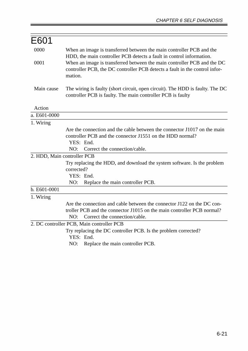
CHAPTER 6 SELF DIAGNOSIS
6-21
E6010000 When an image is transferred between the main controller PCB and the
HDD, the main controller PCB detects a fault in control information.0001 When an image is transferred between the main controller PCB and the DC
controller PCB, the DC controller PCB detects a fault in the control infor-mation.
Main cause The wiring is faulty (short circuit, open circuit). The HDD is faulty. The DCcontroller PCB is faulty. The main controller PCB is faulty
Actiona. E601-0000
1. WiringAre the connection and the cable between the connector J1017 on the maincontroller PCB and the connector J1551 on the HDD normal?
YES: End.NO: Correct the connection/cable.
2. HDD, Main controller PCBTry replacing the HDD, and download the system software. Is the problemcorrected?
YES: End.NO: Replace the main controller PCB.
b. E601-0001
1. WiringAre the connection and cable between the connector J122 on the DC con-troller PCB and the connector J1015 on the main controller PCB normal?
NO: Correct the connection/cable.2. DC controller PCB, Main controller PCB
Try replacing the DC controller PCB. Is the problem corrected?YES: End.NO: Replace the main controller PCB.
CHAPTER 6 SELF DIAGNOSIS
6-22
E6020001 A mounting fault of the HDD is detected when the HDD is started up from
the BOOT ROM.0002 A data read fault of the HDD is detected when the HDD is started up from
the BOOT ROM.
Main cause The wiring is faulty (short circuit, open circuit). The HDD is faulty. Themain controller PCB is faulty.
Action1. Wiring
Are the connection and the cable between connector J1025 of the main con-troller PCB and the connector J2005 of the HDD normal?
NO: Correct the connector/cable.2. System software
Try re-installing the system software. Is the problem corrected?YES: End.
3. HDD, Main controller PCBTry replacing the HDD, and download the system software. Is the problemcorrected?
YES: End.NO: Replace the main controller PCB.
E6040000 A fault is detected in the image memory.
Main cause The wiring is faulty (short circuit, open circuit). The HDD is faulty. Themain controller PCB is faulty.
E6050001 A fault is detected in the battery for the image memory.
Main cause The wiring is faulty (short circuit, open circuit). The HDD is faulty. Themain controller PCB is faulty.
CHAPTER 6 SELF DIAGNOSIS
6-23
E6060001 A mounting fault of the HDD is detected when the HDD is started up from
the BOOT ROM.
Main cause The HDD is faulty. The main controller PCB is faulty.
Making Corrections1. Wiring
Are the connection and cable normal between the connector J1025 on themain controller PCB and the connector J2005 of the HDD?
NO: Correct the connection and the cable.2. System software
Try re-installing the system software. Is the problem corrected?YES: End.
3. HDD, Main controller PCBTry replacing the HDD and downloading the system software. Is the prob-lem corrected?
YES: End.NO: Replace the main controller PCB.
E6740000 A faulty occurs in the communication between the fax PCB and the main
controller PCB.
Main cause The wiring is faulty (short circuit, open circuit). The fax PCB is faulty. Themain controller PCB is faulty.
Making Corrections1. Wiring
Are the connection and the cable between the connector J 1005 on the maincontroller PCB and the connector J31 on the FAX PCB normal?
NO: Correct the connection and the cable.2. FAX PCB, Main controller PCB
Try replacing the FAX PCB. Is the problem corrected?YES: End.NO: Replace the main controller PCB.
CHAPTER 6 SELF DIAGNOSIS
6-24
E6770001 A fault occurs it the combination between any of the printer boards (acces-
sories) and the main controller PCB.
Main cause Any of the printer boards (accessories) is faulty. The main controller PCB isfaulty.
Action1. Connector
Is the printer board (accessory) connected correctly?NO: Correct the connection.
2. Printer board, Main controller PCBTry replacing the printer board. Is the problem corrected?
YES: End.NO: Replace the main controller PCB.
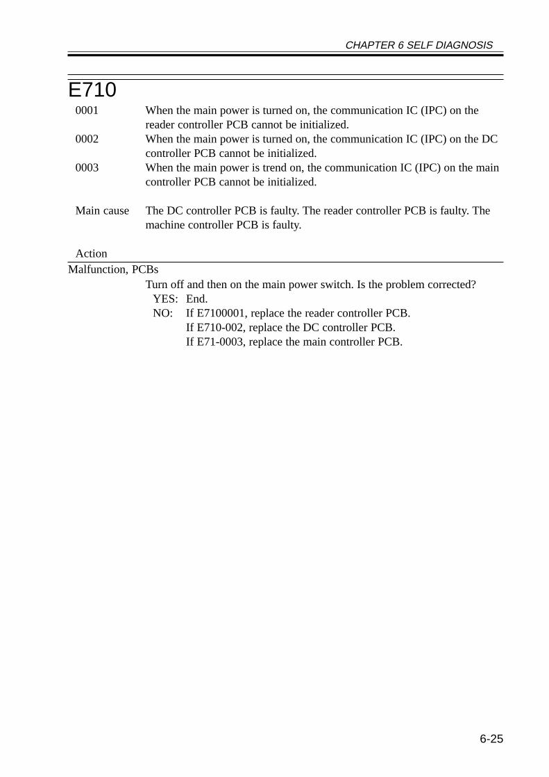
CHAPTER 6 SELF DIAGNOSIS
6-25
E7100001 When the main power is turned on, the communication IC (IPC) on the
reader controller PCB cannot be initialized.0002 When the main power is turned on, the communication IC (IPC) on the DC
controller PCB cannot be initialized.0003 When the main power is trend on, the communication IC (IPC) on the main
controller PCB cannot be initialized.
Main cause The DC controller PCB is faulty. The reader controller PCB is faulty. Themachine controller PCB is faulty.
ActionMalfunction, PCBs
Turn off and then on the main power switch. Is the problem corrected?YES: End.NO: If E7100001, replace the reader controller PCB.
If E710-002, replace the DC controller PCB.If E71-0003, replace the main controller PCB.
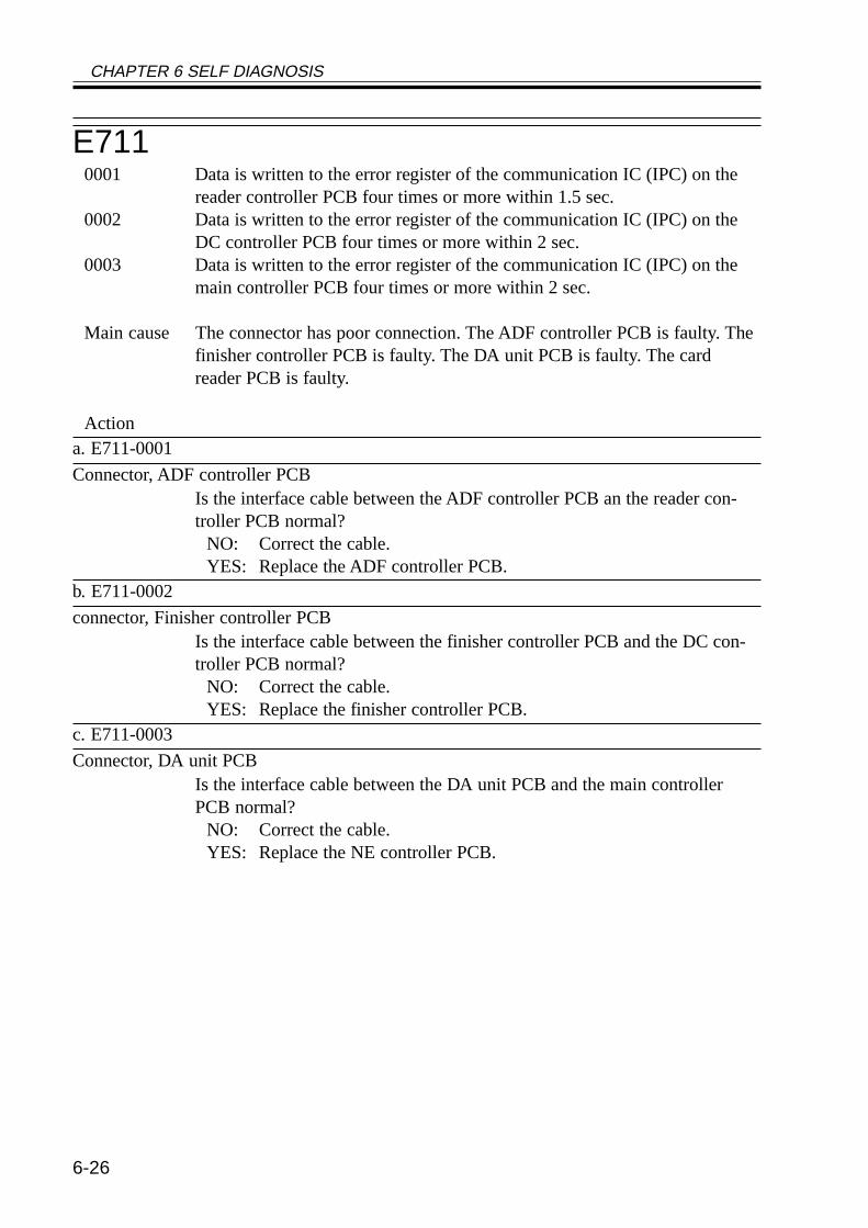
CHAPTER 6 SELF DIAGNOSIS
6-26
E7110001 Data is written to the error register of the communication IC (IPC) on the
reader controller PCB four times or more within 1.5 sec.0002 Data is written to the error register of the communication IC (IPC) on the
DC controller PCB four times or more within 2 sec.0003 Data is written to the error register of the communication IC (IPC) on the
main controller PCB four times or more within 2 sec.
Main cause The connector has poor connection. The ADF controller PCB is faulty. Thefinisher controller PCB is faulty. The DA unit PCB is faulty. The cardreader PCB is faulty.
Actiona. E711-0001
Connector, ADF controller PCBIs the interface cable between the ADF controller PCB an the reader con-troller PCB normal?
NO: Correct the cable.YES: Replace the ADF controller PCB.
b. E711-0002
connector, Finisher controller PCBIs the interface cable between the finisher controller PCB and the DC con-troller PCB normal?
NO: Correct the cable.YES: Replace the finisher controller PCB.
c. E711-0003
Connector, DA unit PCBIs the interface cable between the DA unit PCB and the main controllerPCB normal?
NO: Correct the cable.YES: Replace the NE controller PCB.
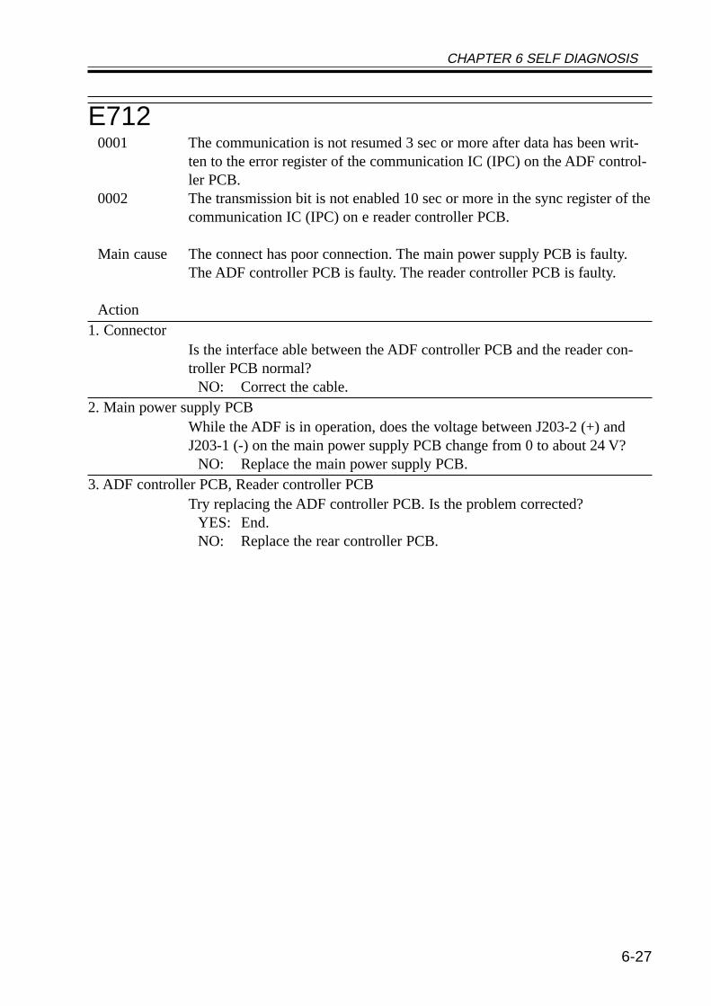
CHAPTER 6 SELF DIAGNOSIS
6-27
E7120001 The communication is not resumed 3 sec or more after data has been writ-
ten to the error register of the communication IC (IPC) on the ADF control-ler PCB.
0002 The transmission bit is not enabled 10 sec or more in the sync register of thecommunication IC (IPC) on e reader controller PCB.
Main cause The connect has poor connection. The main power supply PCB is faulty.The ADF controller PCB is faulty. The reader controller PCB is faulty.
Action1. Connector
Is the interface able between the ADF controller PCB and the reader con-troller PCB normal?
NO: Correct the cable.2. Main power supply PCB
While the ADF is in operation, does the voltage between J203-2 (+) andJ203-1 (-) on the main power supply PCB change from 0 to about 24 V?
NO: Replace the main power supply PCB.3. ADF controller PCB, Reader controller PCB
Try replacing the ADF controller PCB. Is the problem corrected?YES: End.NO: Replace the rear controller PCB.
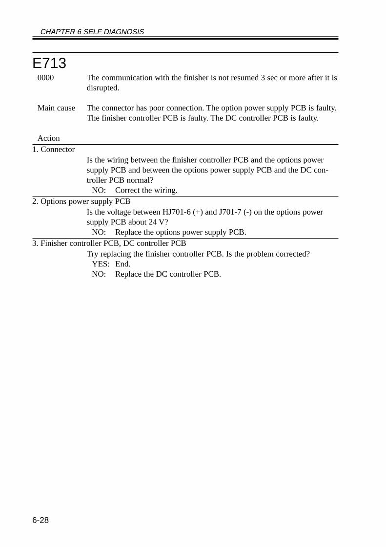
CHAPTER 6 SELF DIAGNOSIS
6-28
E7130000 The communication with the finisher is not resumed 3 sec or more after it is
disrupted.
Main cause The connector has poor connection. The option power supply PCB is faulty.The finisher controller PCB is faulty. The DC controller PCB is faulty.
Action1. Connector
Is the wiring between the finisher controller PCB and the options powersupply PCB and between the options power supply PCB and the DC con-troller PCB normal?
NO: Correct the wiring.2. Options power supply PCB
Is the voltage between HJ701-6 (+) and J701-7 (-) on the options powersupply PCB about 24 V?
NO: Replace the options power supply PCB.3. Finisher controller PCB, DC controller PCB
Try replacing the finisher controller PCB. Is the problem corrected?YES: End.NO: Replace the DC controller PCB.
CHAPTER 6 SELF DIAGNOSIS
6-29
E7160000 The ID signal is not detected within a specific period of time after the pres-
ence of a pedestal is detected.
Main cause The connector has poor connection. The main power supply PCB is faulty.The pedestal controller PCB is faulty. The DC controller PCB is faulty.
Action1. Connector
Is the wiring between the pedestal controller PCB and the main power sup-ply PCB and between the main power supply PCB and the DC controllerPCB normal?
NO: Correct the wiring.2. Main power supply PCB
Is the voltage between J206-2 (+) and J206-1 (-) on the main power supplyPCB about 24 V?
NO: Replace the main power supply PCB.3. Pedestal controller PCB, DC controller PCB
Try replacing the pedestal controller PCB. Is the problem corrected?YES: End.NO: Replace the DC controller.
E7170001 The communication with the DA unit is not resumed 3 sec or more after it is
disrupted.
Main cause The wiring is faulty (short circuit, open circuit). The DA unit PCB is faulty.The main controller PCB is faulty.
Caution To clear the error, execute the following in service mode:COPIER>FUNCTION>CLEAR>ERR.
Action1. Connector
Is the connection between the DA unit PCB and the main controller PCBsecure?
NO: Correct the connection.2. DA unit PCB, main controller PCB
Try replacing the DA unit PCB. Is the problem corrected?YES: End.NO: Replace the main controller PCB.
CHAPTER 6 SELF DIAGNOSIS
6-30
E7190001 The communication between the Card Reader-C1 or the coin vendor and the
main controller PCB is disrupted.
Main cause The wiring is faulty (short circuit, open circuit). The Card Reader-C1 isfaulty. The coin vendor is faulty. The main controller PCB is faulty.
Caution To clear the error, execute the following in service mode:COPIER>FUNCTION>CLEAR>ERR.
Action1. Connector
Is the Cad Reader-C1 or the coin vendor connected securely?NO: Connect it securely.
2. Coin vendor, Main controller PCBTry replacing the Card Reader-C1 or the coin vendor. Is the problem cor-rected?
YES: End.NO: Replace the main controller PCB.
E7320001 A fault is detected by the main controller PCB in the communication be-
tween reader controller PCB and the main controller PCB.
Main cause The connector has poor connection. The reader controller PCB is faulty.
Action1. Connector, Reader controller PCB
Is the connection between the connector J1014 on the main controller PCBand the connector J409 on the reader controller PCB normal?
NO: Correct the connection.YES: Replace the reader controller PCB.
CHAPTER 6 SELF DIAGNOSIS
6-31
E7330001 A fault is detected by the main controller PCB in the communication be-
tween the DC controller PCB and the main controller PCB.
Main cause The connector has poor connection. The DC controller PCB is faulty.
Action1. Connector, DC controller PCB
Is the connection between the connector J1015 on the main controller PCBand the conductor J316 on the DC controlled PCB normal?
NO: Correct the connection.YES: Replace the DC controller PCB.
E7370000 During self diagnosis at power-on, the DRAM check finds a fault in the
main controller PCB.
Main cause The connection of the IC socket is faulty. The main controller PCB is faulty.
Action1. Connection
Is the DRAM fitted to the socket securely?NO: Fit the DRAM securely.
2. DRAM, Main controller PCBTry replacing the DRAM. Is the problem corrected?
YES: End.NO: Replace the main controller PCB.
CHAPTER 6 SELF DIAGNOSIS
6-32
E7400001 At power-on, the LAN card has a fault.0002 The MAC address has a fault.0003 The LAN card cannot be read.
Main cause The LAN card is faulty. The main controller PCB is faulty.
Action1. Connector
Is the connection between the LAN card and the main controller PCB nor-mal?
NO: Correct the connection.2. LAN card, Main controller PCB
Try replacing the LAN card. Is the problem corrected?YES: End.NO: Replace the main controller PCB.
E7410000 The PCI bus has a fault.
Main cause The PCI bus has poor connection. The main controller PCB is faulty.
Action Each PCI slot may be disabled in service mode to prevent the error:BOARD>PCI1-OFF through PCI3-OFF.
1. BoardIs the connection between the relay board and the main controller PCB nor-mal?
NO: Correct the connection.2. Relay board, Main Controller PCB
Try replacing the relay board. Is the problem corrected?YES: End.NO: Replace the main controller PCB.
CHAPTER 6 SELF DIAGNOSIS
6-33
E7430000 The reader controller PCB detects a fault in the communication between the
main controller PCB and the reader controller PCB.
Main cause The connector has poor connection. The main controller PCB has a fault.
Action1. Connector, Main controller PCB
Is the connection between the connector J1014 on the main controller PCBand the connector J409 on the reader controller PCB normal?
NO: Correct the connection.YES: Replace the main controller PCB.
E7440000 The BootROM on the main controller PCB and the system software are for
different models or are of different types.
Main cause The BootROM is not mounted correctly, or a fault occurred during down-loading or when downloading the system software.
Making CorrectionsDownloading (system software)
Check the types of the BootROM and the system software, and downloadsystem software of the correct type.
CHAPTER 6 SELF DIAGNOSIS
6-34
E8030000 The 24V output from the composite main power supply PCB is absent for 1
sec or more.
Main cause The wiring is faulty (short circuit, open circuit). The composite power sup-ply PCB is faulty. The DC controller PCB is faulty.
Making Corrections1. Connectors
Are the connectors J204 on the main power supply PCB and the connectorJ300 on the DC controller PCB connected securely?
NO: Connect the connectors securely.2. Main power supply PCB
Is 24 V supplied by the main power supply PCB (J204) to the DC controllerPCB (J300)?(J204-5 <-> J300-5: OVU3, J204-6 <-> J300-6: OVU3,J204-7 <-> J300-7: 24VU3, J204-8 <-> J300-8: 24VU3)NO: Replace the main power supply PCB.YES: Replace the DC controller PCB.
CHAPTER 6 SELF DIAGNOSIS
6-35
E805The clock signal is absent for 5 sec or more after the fan drive signal hasbeen generated. The detail codes of the fans in question are as follows:
0001 developing fan (FM1)0002 fixing fan (FM2)0003 curl reducing fan (FM4)0004 curl reducing fan (FM5)0005 electrical unit fan (FM3)
Main cause The fan wiring is faulty (short circuit, open circuit). The fan is faulty. TheDC controller PCB is faulty.
Action1. Foreign matter
Is there foreign matter that prevents the rotation of the fan?YES: Remove the foreign matter.
2. Wiring, ConnectorAre the wiring and connector of the fan normal?Developing fan (FM1): DC controller PCB (J302B)Fixing fan (FM2): DC controller PCB (J308B)Curl reducing fan (FM4): DC controller PCB (J311B)Curl reducing fan (FM5): DC controller PCB (J311B)Electrical unit fan (FM3): main controller PCB (J1028)
NO: Correct the wiring and the connection.3. Fan, DC controller PCB
Try replacing the fan. Is the problem corrected?YES: End.NO: Replace the DC controller PCB.
CHAPTER 6 SELF DIAGNOSIS
6-36
E9010000 The motor ready signal does not arrive within 1.3 sec after the pedestal
main motor drive signal is generated.
Main cause The connector has poor connector. The pedestal main motor is faulty. Themain power supply PCB is faulty. The pedestal controller PCB is faulty. TheDC controller PCB is faulty.
Action1. Connector
Is the wiring between the pedestal controller PCB and the main power sup-ply PCB and between the main power supply PCB and the DC controllerPCB normal?
NO: Correct the wiring.2. Main power supply PCB
Is the voltage between J206-2 (+) and J206-1 (-) on the main power supplyPCB about 24 V?
NO: Replace the main power supply PCB.3. Pedestal main motor
Try replacing the pedestal main motor. Is the problem corrected?YES: End.
4. Pedestal controller PCB, DC controller PCBTry replacing the pedestal controller PCB. Is the problem corrected?
YES: End.NO: Replace the DC controller PCB.

CHAPTER 6 SELF DIAGNOSIS
6-37
1.2 ADF Error CodesWhen the ADF’s self diagnostic mechanism has gone ON, it may be reset by turning off
and then on its host machine.The host machine can still generate copies in book mode if the ADF cable is discontented
even while the ADF is out of order.
E4200001 When the power switch of the host machine is turned on, the back-up data
from the EEPROM cannot be read or the data that has been read has a fault.
Main cause The EEPROM is faulty. The ADF controller PCB is faulty.
E4210001 The back-up data cannot be written to the EEPROM, or the data that has
been written has a fault.
Main cause The EEPROM has a fault. The ADF controller PCB has a fault.
E4220001 While the ADF is in standby, the communication with its host machine is
disrupted for 5 sec or more; or, while the ADF is in operation, the commu-nication with its host machine is disrupted for 0.5 sec or more.
Main cause The IPC communication is faulty. The communication line has an open cir-cuit. The ADF controller PCB is faulty.
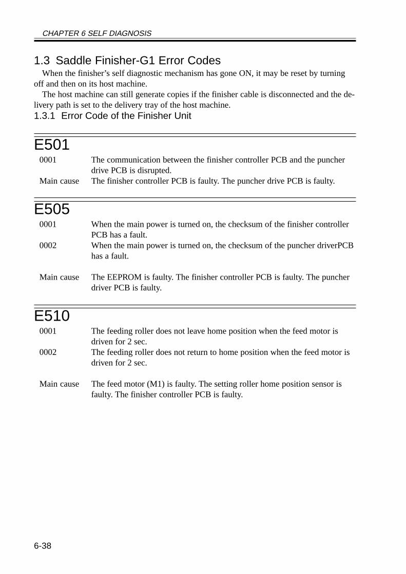
CHAPTER 6 SELF DIAGNOSIS
6-38
1.3 Saddle Finisher-G1 Error CodesWhen the finisher’s self diagnostic mechanism has gone ON, it may be reset by turning
off and then on its host machine.The host machine can still generate copies if the finisher cable is disconnected and the de-
livery path is set to the delivery tray of the host machine.1.3.1 Error Code of the Finisher Unit
E5010001 The communication between the finisher controller PCB and the puncher
drive PCB is disrupted.Main cause The finisher controller PCB is faulty. The puncher drive PCB is faulty.
E5050001 When the main power is turned on, the checksum of the finisher controller
PCB has a fault.0002 When the main power is turned on, the checksum of the puncher driverPCB
has a fault.
Main cause The EEPROM is faulty. The finisher controller PCB is faulty. The puncherdriver PCB is faulty.
E5100001 The feeding roller does not leave home position when the feed motor is
driven for 2 sec.0002 The feeding roller does not return to home position when the feed motor is
driven for 2 sec.
Main cause The feed motor (M1) is faulty. The setting roller home position sensor isfaulty. The finisher controller PCB is faulty.
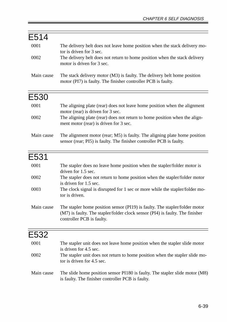
CHAPTER 6 SELF DIAGNOSIS
6-39
E5140001 The delivery belt does not leave home position when the stack delivery mo-
tor is driven for 3 sec.0002 The delivery belt does not return to home position when the stack delivery
motor is driven for 3 sec.
Main cause The stack delivery motor (M3) is faulty. The delivery belt home positionmotor (PI7) is faulty. The finisher controller PCB is faulty.
E5300001 The aligning plate (rear) does not leave home position when the alignment
motor (rear) is driven for 3 sec.0002 The aligning plate (rear) does not return to home position when the align-
ment motor (rear) is driven for 3 sec.
Main cause The alignment motor (rear; M5) is faulty. The aligning plate home positionsensor (rear; PI5) is faulty. The finisher controller PCB is faulty.
E5310001 The stapler does no leave home position when the stapler/folder motor is
driven for 1.5 sec.0002 The stapler does not return to home position when the stapler/folder motor
is driven for 1.5 sec.0003 The clock signal is disrupted for 1 sec or more while the stapler/folder mo-
tor is driven.
Main cause The stapler home position sensor (PI19) is faulty. The stapler/folder motor(M7) is faulty. The stapler/folder clock sensor (PI4) is faulty. The finishercontroller PCB is faulty.
E5320001 The stapler unit does not leave home position when the stapler slide motor
is driven for 4.5 sec.0002 The stapler unit does not return to home position when the stapler slide mo-
tor is driven for 4.5 sec.
Main cause The slide home position sensor PI180 is faulty. The stapler slide motor (M8)is faulty. The finisher controller PCB is faulty.
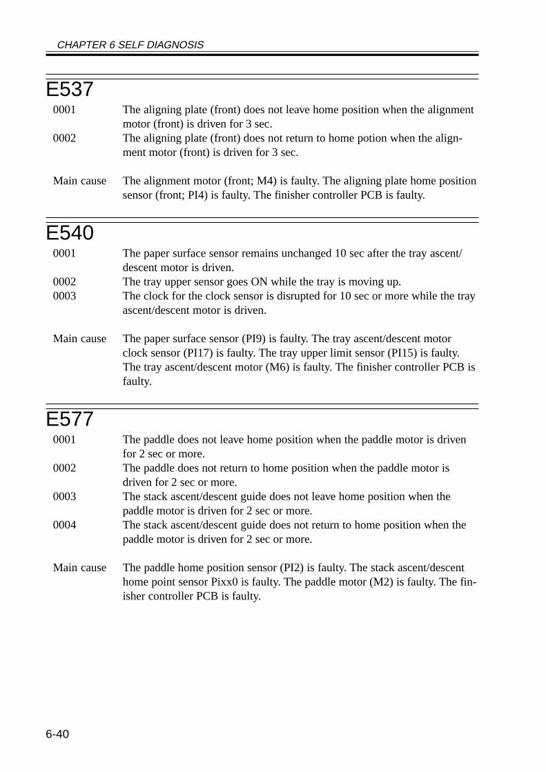
CHAPTER 6 SELF DIAGNOSIS
6-40
E5370001 The aligning plate (front) does not leave home position when the alignment
motor (front) is driven for 3 sec.0002 The aligning plate (front) does not return to home potion when the align-
ment motor (front) is driven for 3 sec.
Main cause The alignment motor (front; M4) is faulty. The aligning plate home positionsensor (front; PI4) is faulty. The finisher controller PCB is faulty.
E5400001 The paper surface sensor remains unchanged 10 sec after the tray ascent/
descent motor is driven.0002 The tray upper sensor goes ON while the tray is moving up.0003 The clock for the clock sensor is disrupted for 10 sec or more while the tray
ascent/descent motor is driven.
Main cause The paper surface sensor (PI9) is faulty. The tray ascent/descent motorclock sensor (PI17) is faulty. The tray upper limit sensor (PI15) is faulty.The tray ascent/descent motor (M6) is faulty. The finisher controller PCB isfaulty.
E5770001 The paddle does not leave home position when the paddle motor is driven
for 2 sec or more.0002 The paddle does not return to home position when the paddle motor is
driven for 2 sec or more.0003 The stack ascent/descent guide does not leave home position when the
paddle motor is driven for 2 sec or more.0004 The stack ascent/descent guide does not return to home position when the
paddle motor is driven for 2 sec or more.
Main cause The paddle home position sensor (PI2) is faulty. The stack ascent/descenthome point sensor Pixx0 is faulty. The paddle motor (M2) is faulty. The fin-isher controller PCB is faulty.
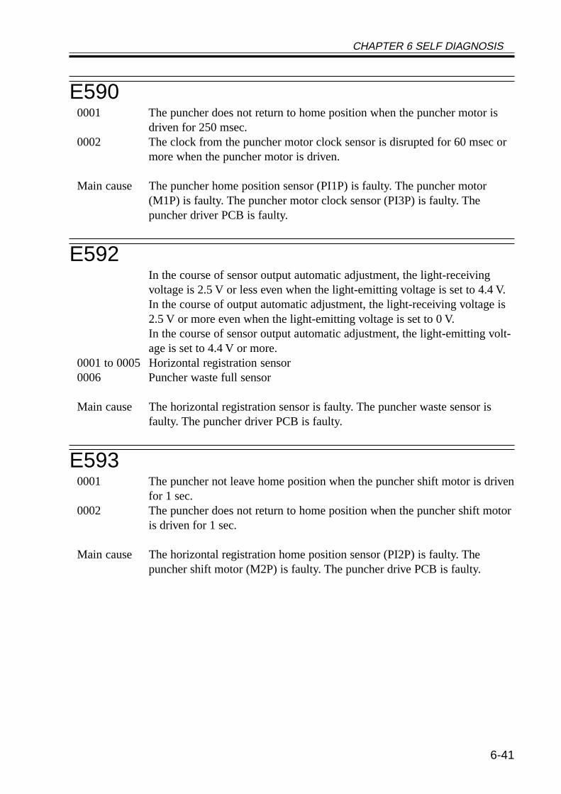
CHAPTER 6 SELF DIAGNOSIS
6-41
E5900001 The puncher does not return to home position when the puncher motor is
driven for 250 msec.0002 The clock from the puncher motor clock sensor is disrupted for 60 msec or
more when the puncher motor is driven.
Main cause The puncher home position sensor (PI1P) is faulty. The puncher motor(M1P) is faulty. The puncher motor clock sensor (PI3P) is faulty. Thepuncher driver PCB is faulty.
E592In the course of sensor output automatic adjustment, the light-receivingvoltage is 2.5 V or less even when the light-emitting voltage is set to 4.4 V.In the course of output automatic adjustment, the light-receiving voltage is2.5 V or more even when the light-emitting voltage is set to 0 V.In the course of sensor output automatic adjustment, the light-emitting volt-age is set to 4.4 V or more.
0001 to 0005 Horizontal registration sensor0006 Puncher waste full sensor
Main cause The horizontal registration sensor is faulty. The puncher waste sensor isfaulty. The puncher driver PCB is faulty.
E5930001 The puncher not leave home position when the puncher shift motor is driven
for 1 sec.0002 The puncher does not return to home position when the puncher shift motor
is driven for 1 sec.
Main cause The horizontal registration home position sensor (PI2P) is faulty. Thepuncher shift motor (M2P) is faulty. The puncher drive PCB is faulty.
CHAPTER 6 SELF DIAGNOSIS
6-42
E5F10001 The folding roller does not leave home position when the stapler/folder mo-
tor is driven for 1.5 sec.0002 The folding roller does to return to home position when the stapler/folder
motor is driven for 3.5 sec or more.0003 The clock is disrupted for 1 sec or more while the stapler/folder motor is
driven.
Main cause The folding roller home position sensor (PI12) is faulty. The stapler/foldermotor (M7) is faulty. The stapler/folder clock sensor (PI14) is faulty. Thefinisher controller PCB is faulty.
CHAPTER 6 SELF DIAGNOSIS
6-43
1.4 Finisher-J1 Error CodesWhen the finisher’s self diagnostic mechanism has gone ON, it may be reset by turning
off and then on its host machine.While the finisher is out of order, prints can still be made by disabling the finisher opera-
tion as follows (other than delivery):
1) Service mode[1] Turn off and then on the main power switch.[2] Set '1' to SORTER>OPTION>MD-SPRTN.[3] Turn off and then on the main power switch.
2) User mode[1] Turn off and then on the main power switch.[2] Set 'OFF' the following: 'adjustment/cleaning'>'staple/offset function'.[3] Turn off and then on the main power switch.
E5000000 The communication between the copier and the finisher is disrupted and is
not corrected for 5 sec or less.
Cause The copier harness is faulty. (disconnected connector, open circuit) The fin-isher controller PCB or the copier’s DC controller PCB is faulty.
E5140000 At the start of the motor CW operation, the stack handling motor (M2) may
be driven for a specific number of rotations; however, the stack delivery le-ver home position sensor (S8) does not go ON.
Cause The stack handling motor (M2) is faulty. The stack delivery lever home po-sition sensor (S8) is faulty, the connector is disconnected, or an open circuitexits. The stack handling motor (M2) relay harness is faulty. The returnroller is faulty.
E5300000 The alignment motor (M4) is driven for a specific number of rotations, but
the aligning plate home position sensor (S7) does not go ON.The alignment motor (M4) is driven for a specific number of rotations, butthe aligning plate home position sensor (S7) does not go OFF.
Cause The rear alignment motor (M4) is faulty. The rear aligning plate home posi-tion sensor (S7) is faulty. The rear alignment motor relay harness is faulty.The rear aligning plate is subjected to an excess load.
CHAPTER 6 SELF DIAGNOSIS
6-44
E5310000 The stapling home position sensor (S16) does not go off 0.5 sec after the
stapler motor is rotated CW.The stapling home position sensor (S16) dos not go ON with 0.5 sec afterthe stapler motor is rotated CW and, thereafter, the sensor does not go ONwithin 0.5 sec after the motor is rotated in reverse.
Cause The stapler motor (M6) is faulty. The stapling home position sensor (S16) isfaulty. The stapler harness is faulty. The finisher controller PCB is faulty.
E5370000 The aligning plate home position sensor (S6) does not go ON when the
front alignment motor (M3) is driven for a specific number of rotations.The aligning plate home position sensor (S6) does not go OFF when thefront alignment motor (M3) is driven for a specific number of rotations.
Cause The front alignment motor (M3) is faulty. The front aligning plate home po-sition sensor (S6) is faulty. The front alignment motor relay harness isfaulty. The front aligning plate is subjected to an excess load.
E5770000 The return roller does not reach home position when the delivery motor
(Ml) has been driven as much as will move it to the return roller home posi-tion sensor (S3).
Cause The delivery motor (M1) or the finisher controller PCB is faulty. The returnroller home position sensor (S3) is faulty, the harness connector is discon-nected, or an open circuit exits. The delivery motor relay harness is faulty.The return roller is faulty.
CHAPTER 6 SELF DIAGNOSIS
6-45
E5800000 The delivery tray upper limit sensor (S13) goes ON while the delivery tray
ascent/descent motor (M5) is in operation.The clock signal of the delivery tray ascent/descent motor clock sensor (S9)is not detected 15 times or more within 0.8 sec while the delivery tray as-cent/descent motor (M5) is in operation.The delivery tray paper height sensor (S10) does not go ON 4 sec after thedelivery tray ascent/descent motor (M5) starts to move up.The delivery tray paper height sensor (S10) does not go OFF 4 sec after thedelivery tray ascent/descent motor (M5) starts to move down.
Cause The delivery tray ascent/descent motor (M5) is faulty. The delivery tray pa-per height sensor (S10) is faulty, the harness is disconnected, or an open cir-cuit exits. The delivery tray ascent/descent motor lock sensor (S9) is faulty,the connector is disconnected, or an open circuit exits. The delivery trayascent/descent motor is subjected to an excess load. The finisher controllerPCB is faulty.
E5850000 At the start of the motor CCW operation, the stack handling motor (M2)
may be driven for a specific number of rotations; however, the stack deliv-ery lever home position sensor (S8) does not go ON.
Cause The stack handling motor (M2) is faulty. The stack delivery lever home po-sition sensor (S8) is faulty, the connector is disconnected, or an open circuitexits. The stack handling motor (M2) relay harness is faulty. The returnroller is faulty.

CHAPTER 7 UPGRADING
7-1
CHAPTER 7 UPGRADING
1 Upgrading
1.1 OutlineThe machine is upgraded either by downloading data from a PC or by replacing its
DIMM/ROM.The following five items are upgraded by downloading from a PC:
• BOOT ROM (machine J1009 DIMM ROM)• HD Format (machine HDD; formatting)• Language (machine HDD)• RUI (machine HDD)• System (machine HDD)• DADF-H1 (CPU; Use the downloader PCB) See 1.6 Downloader PCB• Finisher-J1 (CPU; Use the downloader PCB) See 1.6 Downloader PCB
As indicated, the language module may also be downloaded.The machine may be connected to a network when downloading data from a PC.For instructions on upgrading by means of replacing the DIMM/ROM, see 1.7 “Upgrad-
ing by Replacing the DIMM/ROM.”
1.1.1 Download ModeThe machine provides two types of download modes; although any of the two may be
used to download all files, select with care if you want to format the hard disk (select the HDFormat), as a specific partition must be selected.
You can use any of the two when using a parallel cable; however, the use of a networkcable will require you to start up the machine’s network environment, necessitating the useof downloading in service mode.• Downloading in Download Mode
To start download mode,1) While holding down ‘2’ and ‘8’ on the keypad at the same time, turn on the power
switch.2) Hold down ‘2’ and ‘8’ on the keypad until the bottom of the touch panel indicates the
message “Download Mode.”
Partition Available for Formatting the Hard Disk/BOOTDEVALL
7
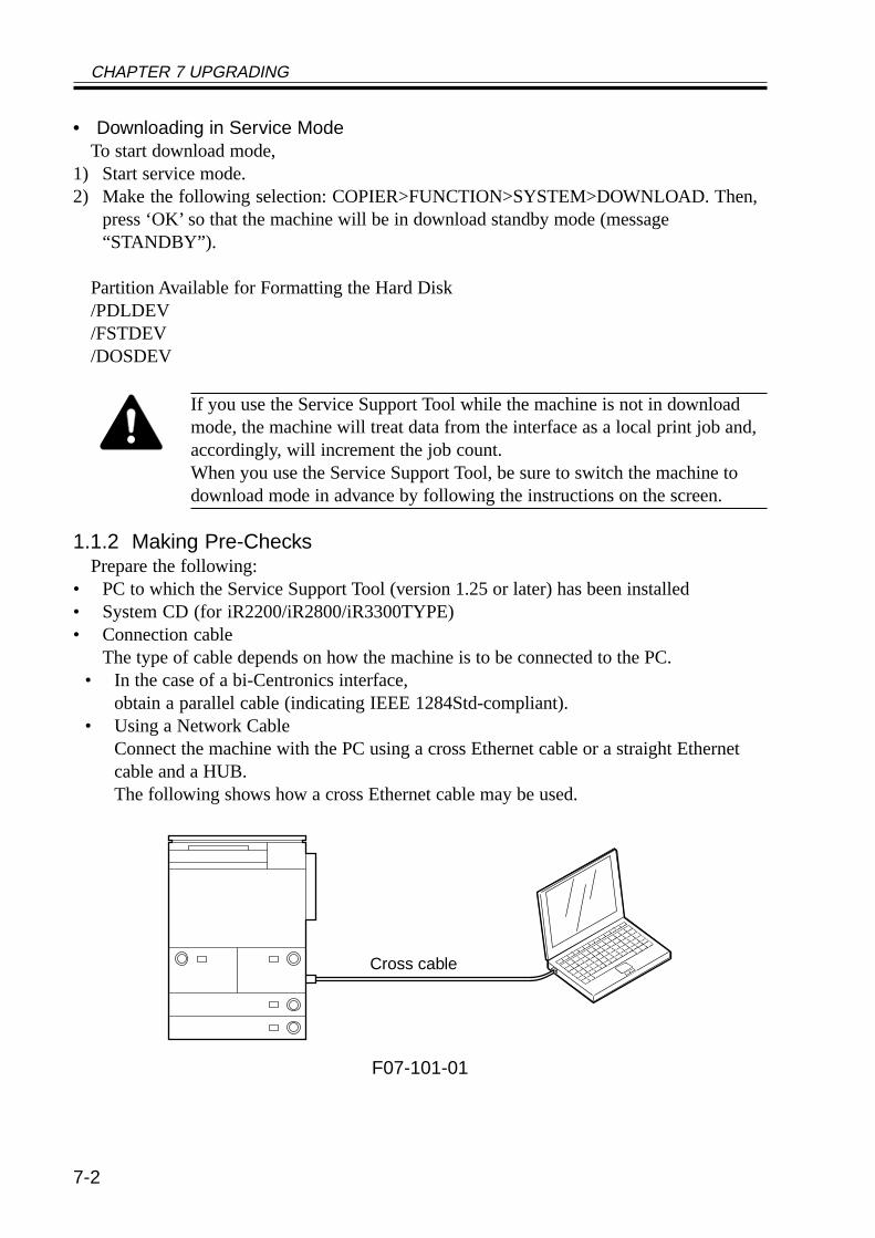
CHAPTER 7 UPGRADING
7-2
• Downloading in Service ModeTo start download mode,
1) Start service mode.2) Make the following selection: COPIER>FUNCTION>SYSTEM>DOWNLOAD. Then,
press ‘OK’ so that the machine will be in download standby mode (message“STANDBY”).
Partition Available for Formatting the Hard Disk/PDLDEV/FSTDEV/DOSDEV
If you use the Service Support Tool while the machine is not in downloadmode, the machine will treat data from the interface as a local print job and,accordingly, will increment the job count.When you use the Service Support Tool, be sure to switch the machine todownload mode in advance by following the instructions on the screen.
1.1.2 Making Pre-ChecksPrepare the following:
• PC to which the Service Support Tool (version 1.25 or later) has been installed• System CD (for iR2200/iR2800/iR3300TYPE)• Connection cable
The type of cable depends on how the machine is to be connected to the PC.• In the case of a bi-Centronics interface,
obtain a parallel cable (indicating IEEE 1284Std-compliant).• Using a Network Cable
Connect the machine with the PC using a cross Ethernet cable or a straight Ethernetcable and a HUB.The following shows how a cross Ethernet cable may be used.
F07-101-01
Cross cable
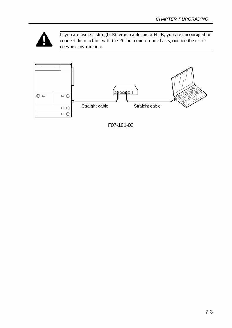
CHAPTER 7 UPGRADING
7-3
If you are using a straight Ethernet cable and a HUB, you are encouraged toconnect the machine with the PC on a one-on-one basis, outside the user’snetwork environment.
F07-101-02
Straight cable Straight cable
CHAPTER 7 UPGRADING
7-4
Memo
Differences in Connection Between Bi-Centronics Cable and NetworkCableEach has its own advantages and disadvantages; select one to suit specificneeds:
Connection with a Bi-Centronics Cable (using a parallel cable)Advantages:• You can use the Service Support Tool without considering the environ-
ment of the user’s network.• If the system is not installed on the hard disk, the system may be installed
or the hard disk may be formatted using download mode.Disadvantages:• The specifications of the PC used or the chip set may not allow the use of
high-speed mode, i.e., it has a low level of compatibility.• The PC must have a parallel interface.• You can not use high-speed mode on Windows NT or Windows 2000.
Connection with a Network CableAdvantages:• It is relatively high speed.• It is less dependent on the PC to be used.• The use of a cross cable enables direct connection.Disadvantages:• You must change the network settings of the machine or the PC to suit the
user’s network environment. More importantly, you must change the ma-chine back to its initial settings after the task.
• You must have a good knowledge of networking.• The system must start up normally and the network settings must be cor-
rect.
Memo
Points to Note When Using a Bi-Centronics Interface and a NetworkThe Service Support Tool allows you to select one of two interfaces to suitspecific needs. If both are in use, you must turn the machine off and then onfirst before making a switch-over (i.e., from Bi-Centronics to Network orvice versa), thereby preventing errors in the event of simultaneous writingoperations.
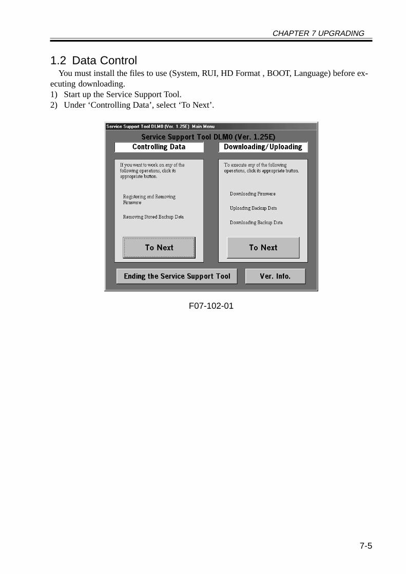
CHAPTER 7 UPGRADING
7-5
1.2 Data ControlYou must install the files to use (System, RUI, HD Format , BOOT, Language) before ex-
ecuting downloading.1) Start up the Service Support Tool.2) Under ‘Controlling Data’, select ‘To Next’.
F07-102-01
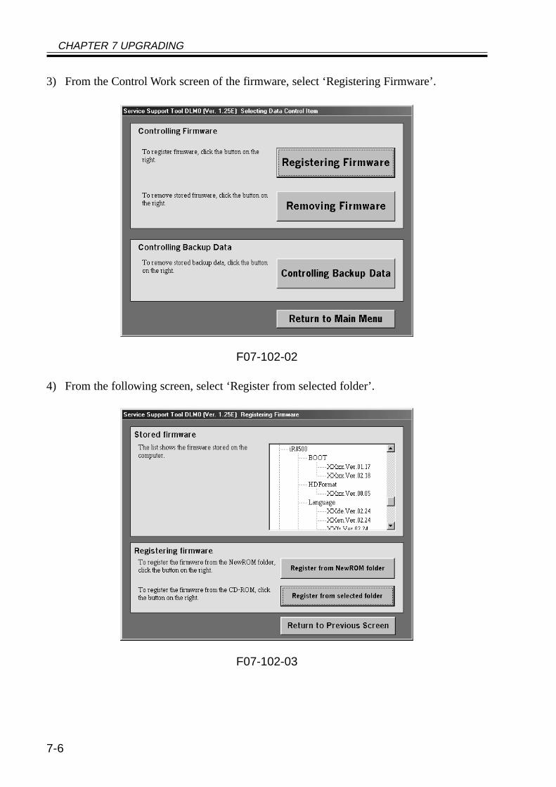
CHAPTER 7 UPGRADING
7-6
3) From the Control Work screen of the firmware, select ‘Registering Firmware’.
F07-102-02
4) From the following screen, select ‘Register from selected folder’.
F07-102-03
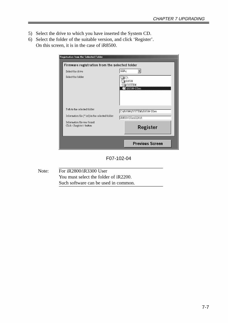
CHAPTER 7 UPGRADING
7-7
5) Select the drive to which you have inserted the System CD.6) Select the folder of the suitable version, and click ‘Register’.
On this screen, it is in the case of iR8500.
F07-102-04
Note: For iR2800/iR3300 UserYou must select the folder of iR2200.Such software can be used in common.
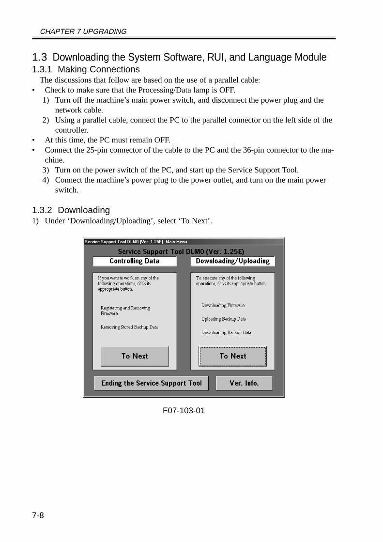
CHAPTER 7 UPGRADING
7-8
1.3 Downloading the System Software, RUI, and Language Module1.3.1 Making Connections
The discussions that follow are based on the use of a parallel cable:• Check to make sure that the Processing/Data lamp is OFF.
1) Turn off the machine’s main power switch, and disconnect the power plug and thenetwork cable.
2) Using a parallel cable, connect the PC to the parallel connector on the left side of thecontroller.
• At this time, the PC must remain OFF.• Connect the 25-pin connector of the cable to the PC and the 36-pin connector to the ma-
chine.3) Turn on the power switch of the PC, and start up the Service Support Tool.4) Connect the machine’s power plug to the power outlet, and turn on the main power
switch.
1.3.2 Downloading1) Under ‘Downloading/Uploading’, select ‘To Next’.
F07-103-01
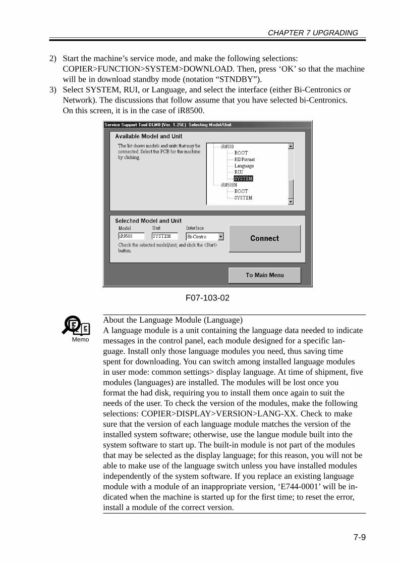
CHAPTER 7 UPGRADING
7-9
2) Start the machine’s service mode, and make the following selections:COPIER>FUNCTION>SYSTEM>DOWNLOAD. Then, press ‘OK’ so that the machinewill be in download standby mode (notation “STNDBY”).
3) Select SYSTEM, RUI, or Language, and select the interface (either Bi-Centronics orNetwork). The discussions that follow assume that you have selected bi-Centronics.On this screen, it is in the case of iR8500.
F07-103-02
Memo
About the Language Module (Language)A language module is a unit containing the language data needed to indicatemessages in the control panel, each module designed for a specific lan-guage. Install only those language modules you need, thus saving timespent for downloading. You can switch among installed language modulesin user mode: common settings> display language. At time of shipment, fivemodules (languages) are installed. The modules will be lost once youformat the had disk, requiring you to install them once again to suit theneeds of the user. To check the version of the modules, make the followingselections: COPIER>DISPLAY>VERSION>LANG-XX. Check to makesure that the version of each language module matches the version of theinstalled system software; otherwise, use the langue module built into thesystem software to start up. The built-in module is not part of the modulesthat may be selected as the display language; for this reason, you will not beable to make use of the language switch unless you have installed modulesindependently of the system software. If you replace an existing languagemodule with a module of an inappropriate version, ‘E744-0001’ will be in-dicated when the machine is started up for the first time; to reset the error,install a module of the correct version.
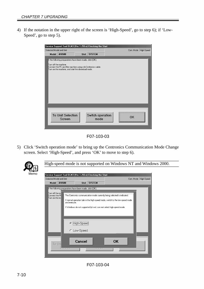
CHAPTER 7 UPGRADING
7-10
4) If the notation in the upper right of the screen is ‘High-Speed’, go to step 6); if ‘Low-Speed’, go to step 5).
F07-103-03
5) Click ‘Switch operation mode’ to bring up the Centronics Communication Mode Changescreen. Select ‘High-Speed’, and press ‘OK’ to move to step 6).
Memo
High-speed mode is not supported on Windows NT and Windows 2000.
F07-103-04
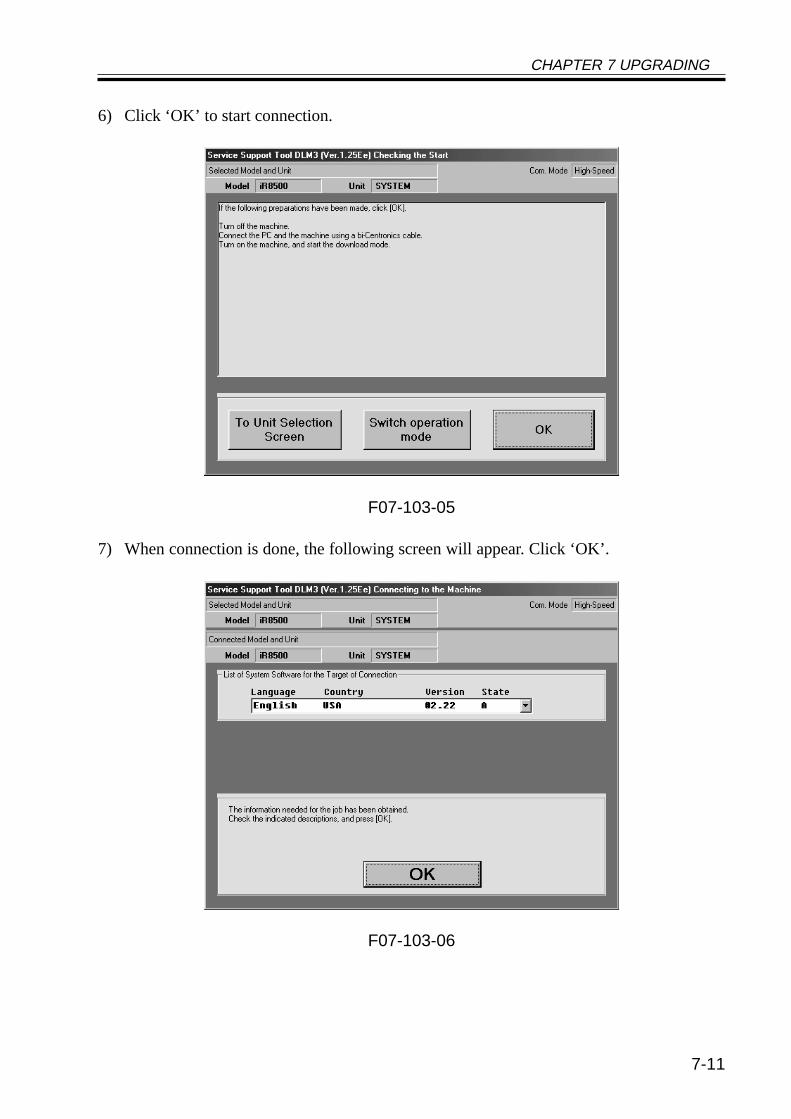
CHAPTER 7 UPGRADING
7-11
6) Click ‘OK’ to start connection.
F07-103-05
7) When connection is done, the following screen will appear. Click ‘OK’.
F07-103-06
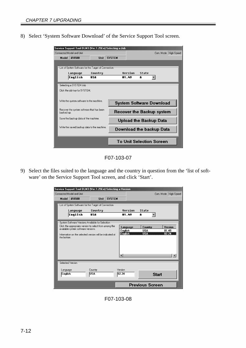
CHAPTER 7 UPGRADING
7-12
8) Select ‘System Software Download’ of the Service Support Tool screen.
F07-103-07
9) Select the files suited to the language and the country in question from the ‘list of soft-ware’ on the Service Support Tool screen, and click ‘Start’.
F07-103-08
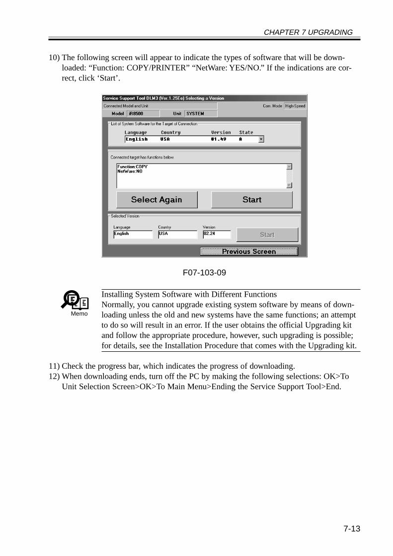
CHAPTER 7 UPGRADING
7-13
10) The following screen will appear to indicate the types of software that will be down-loaded: “Function: COPY/PRINTER” “NetWare: YES/NO.” If the indications are cor-rect, click ‘Start’.
F07-103-09
Memo
Installing System Software with Different FunctionsNormally, you cannot upgrade existing system software by means of down-loading unless the old and new systems have the same functions; an attemptto do so will result in an error. If the user obtains the official Upgrading kitand follow the appropriate procedure, however, such upgrading is possible;for details, see the Installation Procedure that comes with the Upgrading kit.
11) Check the progress bar, which indicates the progress of downloading.12) When downloading ends, turn off the PC by making the following selections: OK>To
Unit Selection Screen>OK>To Main Menu>Ending the Service Support Tool>End.
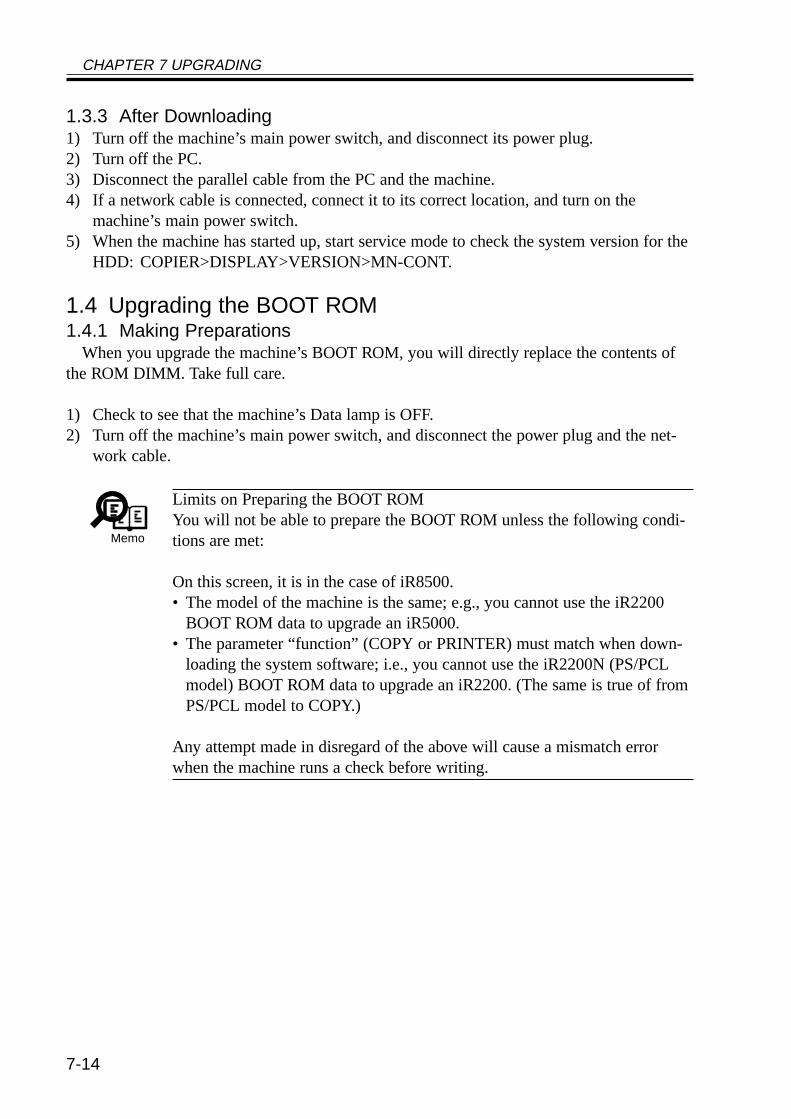
CHAPTER 7 UPGRADING
7-14
1.3.3 After Downloading1) Turn off the machine’s main power switch, and disconnect its power plug.2) Turn off the PC.3) Disconnect the parallel cable from the PC and the machine.4) If a network cable is connected, connect it to its correct location, and turn on the
machine’s main power switch.5) When the machine has started up, start service mode to check the system version for the
HDD: COPIER>DISPLAY>VERSION>MN-CONT.
1.4 Upgrading the BOOT ROM1.4.1 Making Preparations
When you upgrade the machine’s BOOT ROM, you will directly replace the contents ofthe ROM DIMM. Take full care.
1) Check to see that the machine’s Data lamp is OFF.2) Turn off the machine’s main power switch, and disconnect the power plug and the net-
work cable.
Memo
Limits on Preparing the BOOT ROMYou will not be able to prepare the BOOT ROM unless the following condi-tions are met:
On this screen, it is in the case of iR8500.• The model of the machine is the same; e.g., you cannot use the iR2200
BOOT ROM data to upgrade an iR5000.• The parameter “function” (COPY or PRINTER) must match when down-
loading the system software; i.e., you cannot use the iR2200N (PS/PCLmodel) BOOT ROM data to upgrade an iR2200. (The same is true of fromPS/PCL model to COPY.)
Any attempt made in disregard of the above will cause a mismatch errorwhen the machine runs a check before writing.
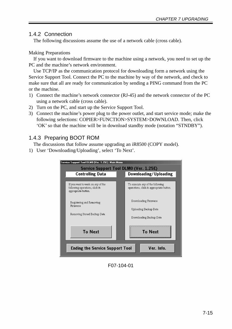
CHAPTER 7 UPGRADING
7-15
1.4.2 ConnectionThe following discussions assume the use of a network cable (cross cable).
Making PreparationsIf you want to download firmware to the machine using a network, you need to set up the
PC and the machine’s network environment.Use TCP/IP as the communication protocol for downloading form a network using the
Service Support Tool. Connect the PC to the machine by way of the network, and check tomake sure that all are ready for communication by sending a PING command from the PCor the machine.1) Connect the machine’s network connector (RJ-45) and the network connector of the PC
using a network cable (cross cable).2) Turn on the PC, and start up the Service Support Tool.3) Connect the machine’s power plug to the power outlet, and start service mode; make the
following selections: COPIER>FUNCTION>SYSTEM>DOWNLOAD. Then, click‘OK’ so that the machine will be in download standby mode (notation “STNDBY”).
1.4.3 Preparing BOOT ROMThe discussions that follow assume upgrading an iR8500 (COPY model).
1) User ‘Downloading/Uploading’, select ‘To Next’.
F07-104-01
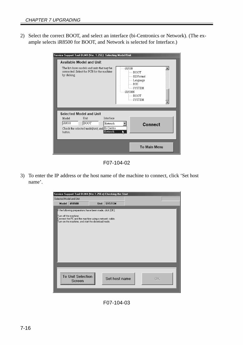
CHAPTER 7 UPGRADING
7-16
2) Select the correct BOOT, and select an interface (bi-Centronics or Network). (The ex-ample selects iR8500 for BOOT, and Network is selected for Interface.)
F07-104-02
3) To enter the IP address or the host name of the machine to connect, click ‘Set hostname’.
F07-104-03
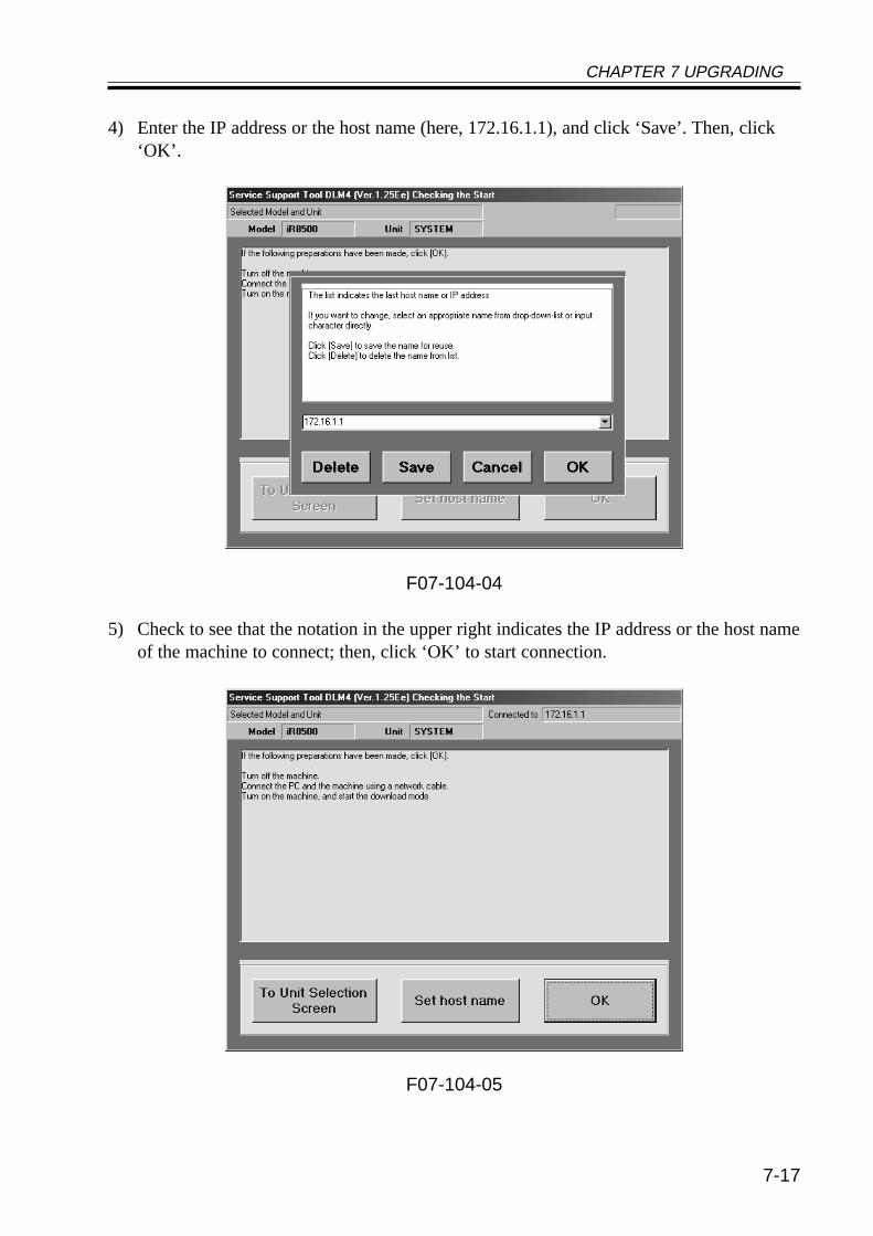
CHAPTER 7 UPGRADING
7-17
4) Enter the IP address or the host name (here, 172.16.1.1), and click ‘Save’. Then, click‘OK’.
F07-104-04
5) Check to see that the notation in the upper right indicates the IP address or the host nameof the machine to connect; then, click ‘OK’ to start connection.
F07-104-05
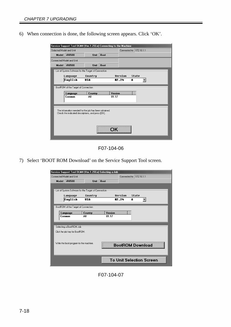
CHAPTER 7 UPGRADING
7-18
6) When connection is done, the following screen appears. Click ‘OK’.
F07-104-06
7) Select ‘BOOT ROM Download’ on the Service Support Tool screen.
F07-104-07
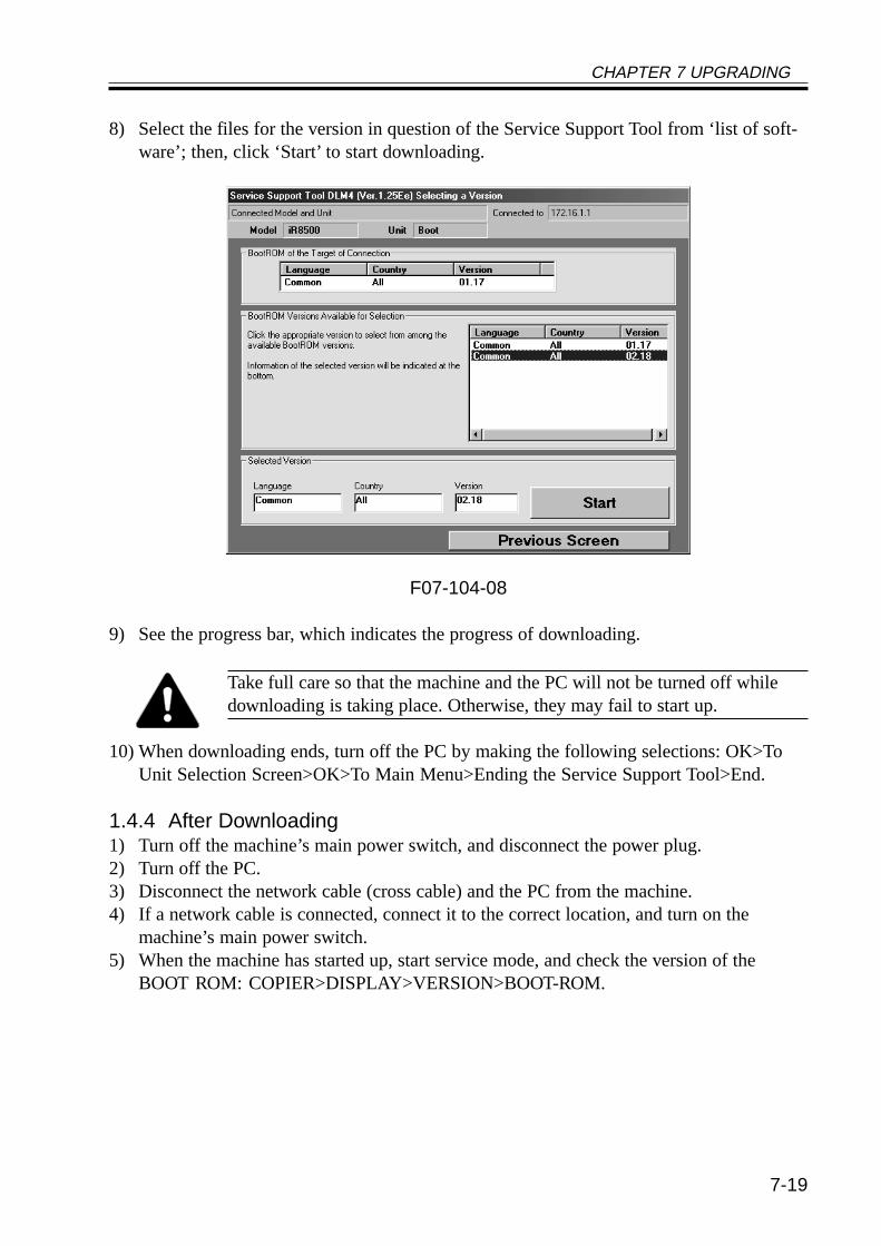
CHAPTER 7 UPGRADING
7-19
8) Select the files for the version in question of the Service Support Tool from ‘list of soft-ware’; then, click ‘Start’ to start downloading.
F07-104-08
9) See the progress bar, which indicates the progress of downloading.
Take full care so that the machine and the PC will not be turned off whiledownloading is taking place. Otherwise, they may fail to start up.
10) When downloading ends, turn off the PC by making the following selections: OK>ToUnit Selection Screen>OK>To Main Menu>Ending the Service Support Tool>End.
1.4.4 After Downloading1) Turn off the machine’s main power switch, and disconnect the power plug.2) Turn off the PC.3) Disconnect the network cable (cross cable) and the PC from the machine.4) If a network cable is connected, connect it to the correct location, and turn on the
machine’s main power switch.5) When the machine has started up, start service mode, and check the version of the
BOOT ROM: COPIER>DISPLAY>VERSION>BOOT-ROM.
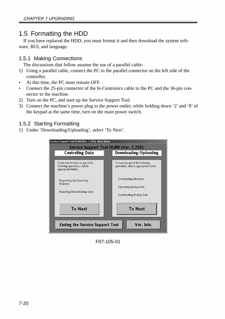
CHAPTER 7 UPGRADING
7-20
1.5 Formatting the HDDIf you have replaced the HDD, you must format it and then download the system soft-
ware, RUI, and language.
1.5.1 Making ConnectionsThe discussions that follow assume the use of a parallel cable:
1) Using a parallel cable, connect the PC to the parallel connector on the left side of thecontroller.
• At this time, the PC must remain OFF.• Connect the 25-pin connector of the bi-Centronics cable to the PC and the 36-pin con-
nector to the machine.2) Turn on the PC, and start up the Service Support Tool.3) Connect the machine’s power plug to the power outlet; while holding down ‘2’ and ‘8’ of
the keypad at the same time, turn on the main power switch.
1.5.2 Starting Formatting1) Under ‘Downloading/Uploading’, select ‘To Next’.
F07-105-01
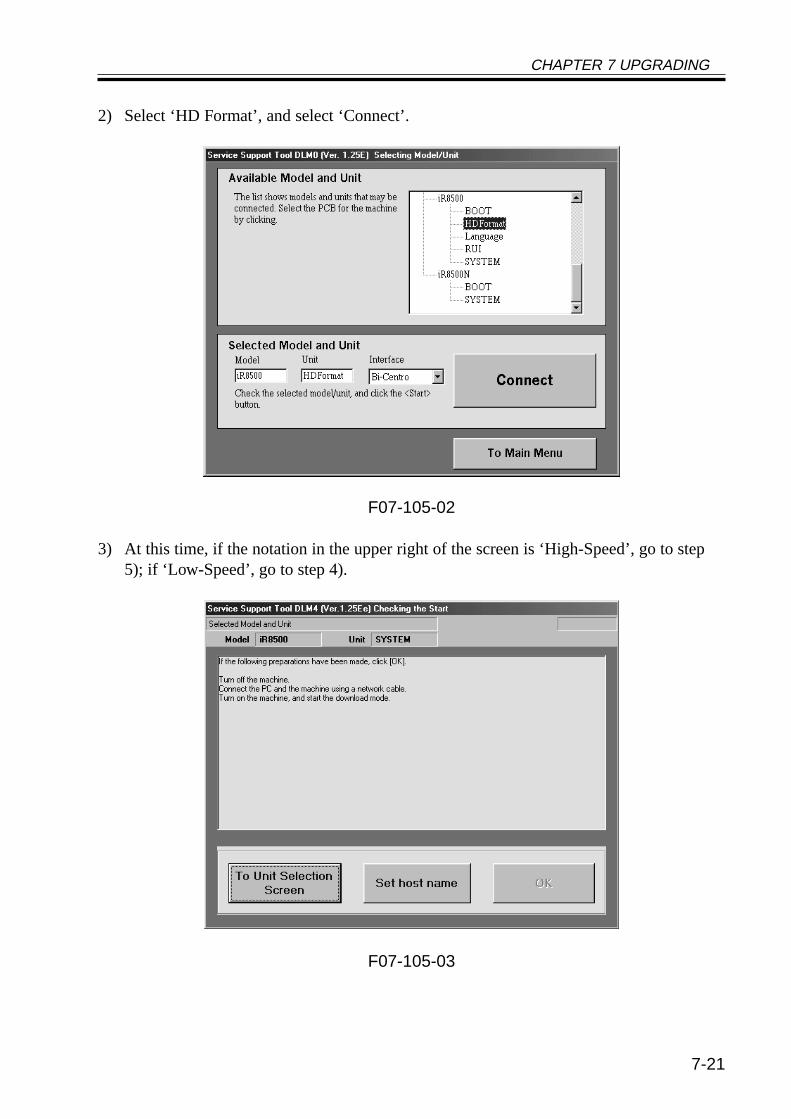
CHAPTER 7 UPGRADING
7-21
2) Select ‘HD Format’, and select ‘Connect’.
F07-105-02
3) At this time, if the notation in the upper right of the screen is ‘High-Speed’, go to step5); if ‘Low-Speed’, go to step 4).
F07-105-03
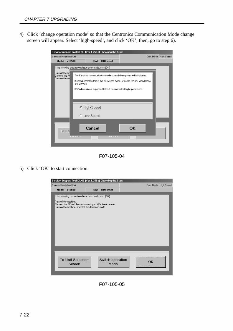
CHAPTER 7 UPGRADING
7-22
4) Click ‘change operation mode’ so that the Centronics Communication Mode changescreen will appear. Select ‘high-speed’, and click ‘OK’; then, go to step 6).
F07-105-04
5) Click ‘OK’ to start connection.
F07-105-05
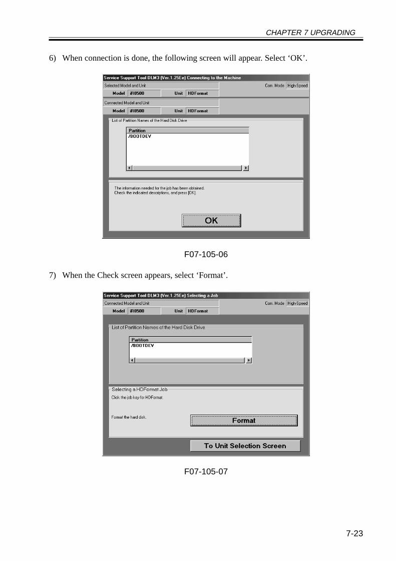
CHAPTER 7 UPGRADING
7-23
6) When connection is done, the following screen will appear. Select ‘OK’.
F07-105-06
7) When the Check screen appears, select ‘Format’.
F07-105-07
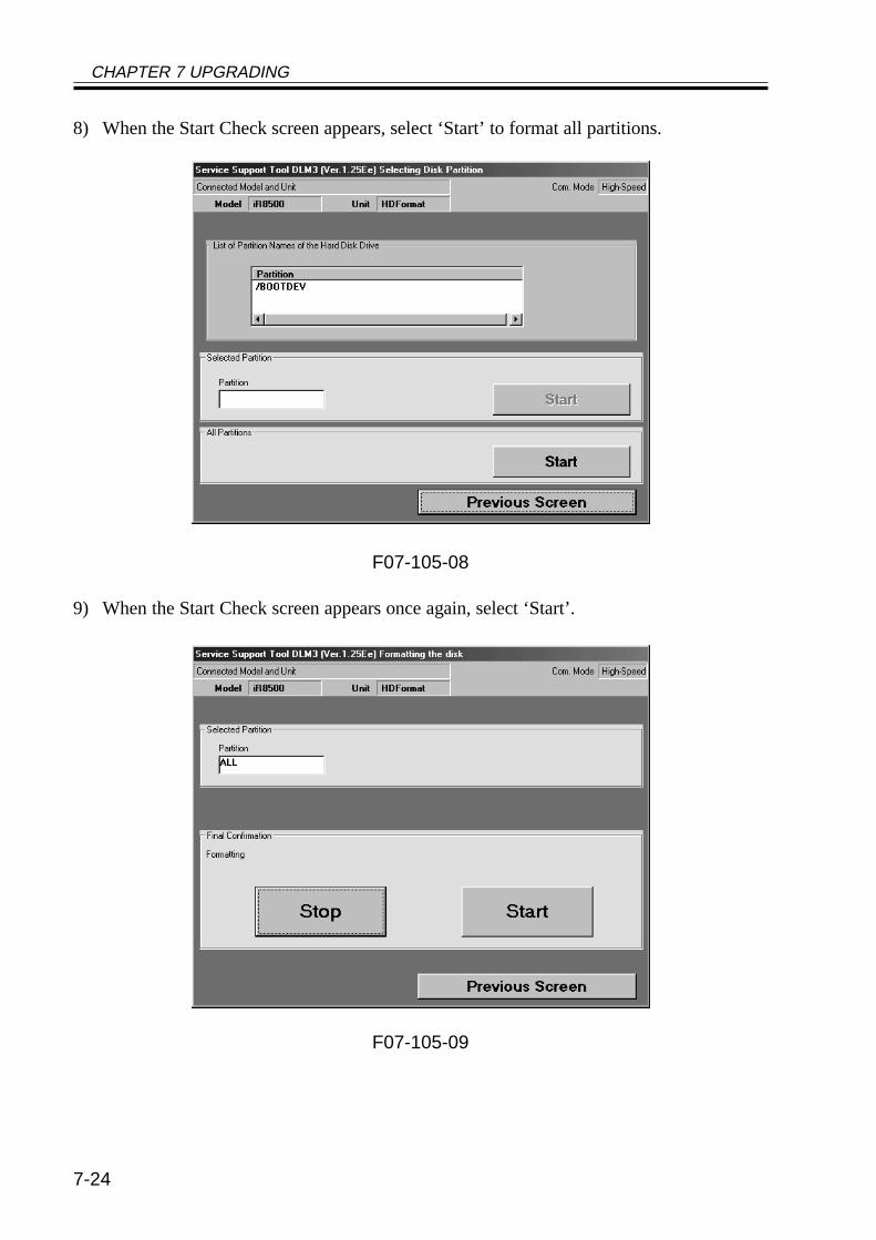
CHAPTER 7 UPGRADING
7-24
8) When the Start Check screen appears, select ‘Start’ to format all partitions.
F07-105-08
9) When the Start Check screen appears once again, select ‘Start’.
F07-105-09
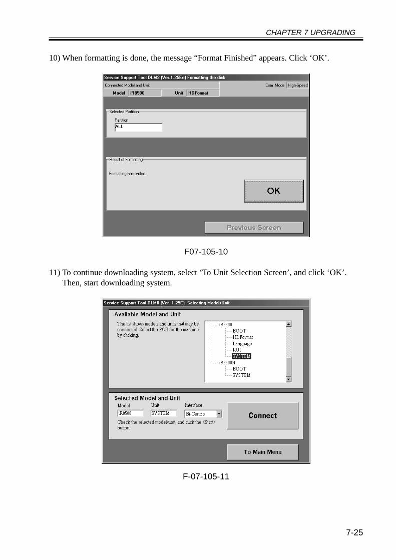
CHAPTER 7 UPGRADING
7-25
10) When formatting is done, the message “Format Finished” appears. Click ‘OK’.
F07-105-10
11) To continue downloading system, select ‘To Unit Selection Screen’, and click ‘OK’.Then, start downloading system.
F-07-105-11
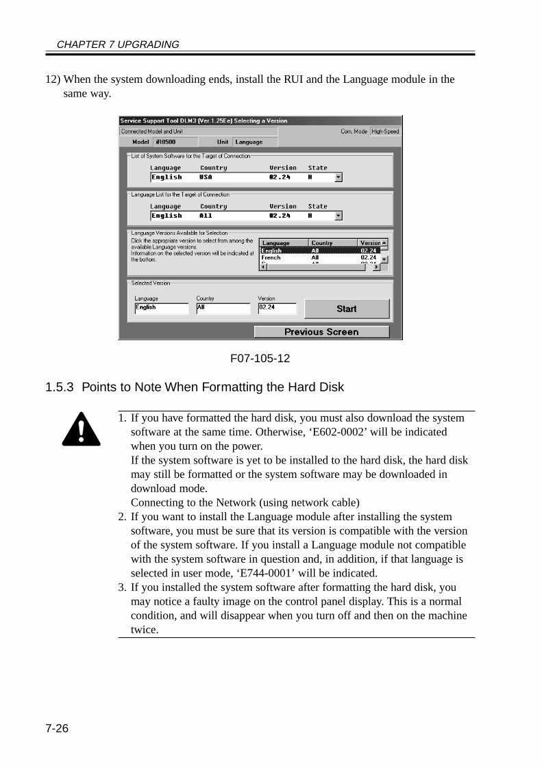
CHAPTER 7 UPGRADING
7-26
12) When the system downloading ends, install the RUI and the Language module in thesame way.
F07-105-12
1.5.3 Points to Note When Formatting the Hard Disk
1. If you have formatted the hard disk, you must also download the systemsoftware at the same time. Otherwise, ‘E602-0002’ will be indicatedwhen you turn on the power.If the system software is yet to be installed to the hard disk, the hard diskmay still be formatted or the system software may be downloaded indownload mode.Connecting to the Network (using network cable)
2. If you want to install the Language module after installing the systemsoftware, you must be sure that its version is compatible with the versionof the system software. If you install a Language module not compatiblewith the system software in question and, in addition, if that language isselected in user mode, ‘E744-0001’ will be indicated.
3. If you installed the system software after formatting the hard disk, youmay notice a faulty image on the control panel display. This is a normalcondition, and will disappear when you turn off and then on the machinetwice.
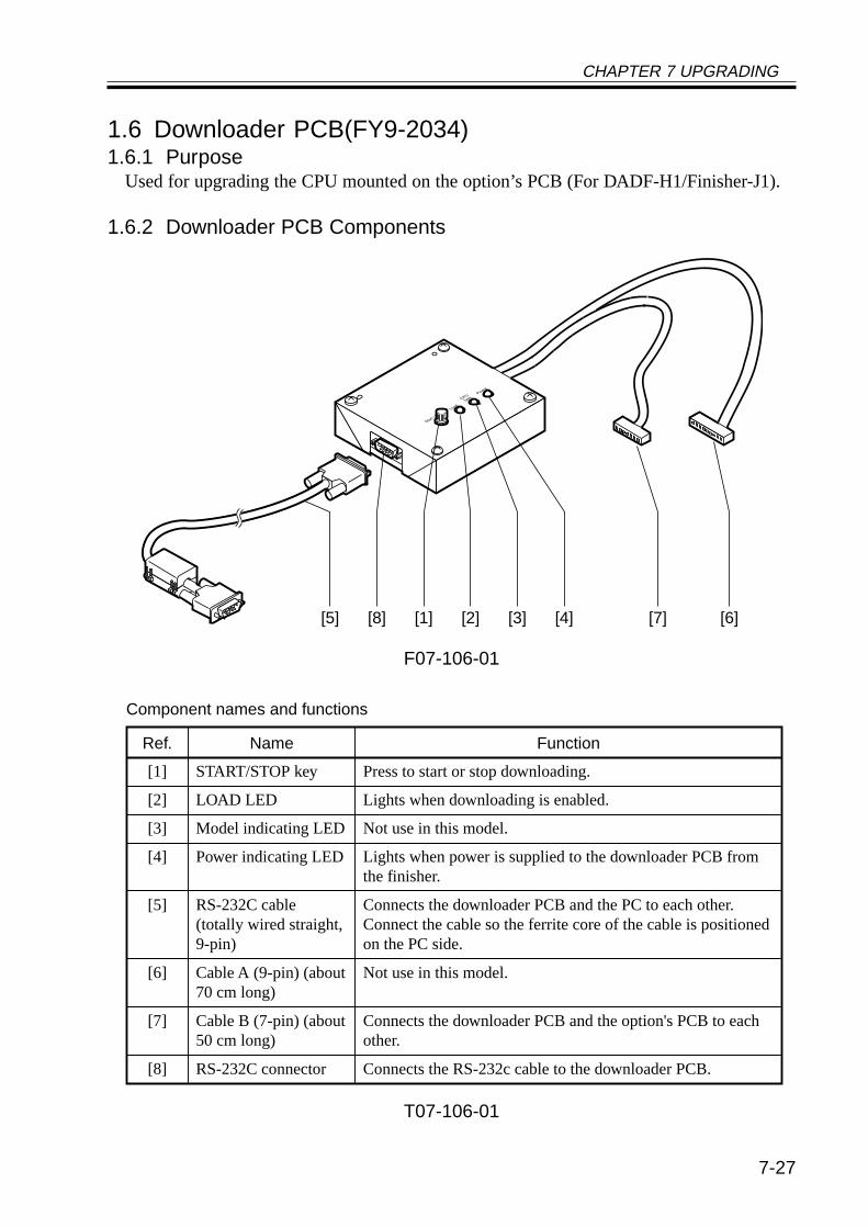
CHAPTER 7 UPGRADING
7-27
1.6 Downloader PCB(FY9-2034)1.6.1 Purpose
Used for upgrading the CPU mounted on the option’s PCB (For DADF-H1/Finisher-J1).
1.6.2 Downloader PCB Components
F07-106-01
T07-106-01
[1] [2] [3] [4] [6][7][5] [8]
[1] START/STOP key
[4] Power indicating LED
Press to start or stop downloading.
[2] LOAD LED Lights when downloading is enabled.
[3] Model indicating LED Not use in this model.
Ref. Name Function
Lights when power is supplied to the downloader PCB from the finisher.
[5] Connects the downloader PCB and the PC to each other. Connect the cable so the ferrite core of the cable is positioned on the PC side.
[6] Cable A (9-pin) (about 70 cm long)
Not use in this model.
[7] Cable B (7-pin) (about 50 cm long)
Connects the downloader PCB and the option's PCB to each other.
[8] RS-232C connector Connects the RS-232c cable to the downloader PCB.
RS-232C cable (totally wired straight, 9-pin)
Component names and functions
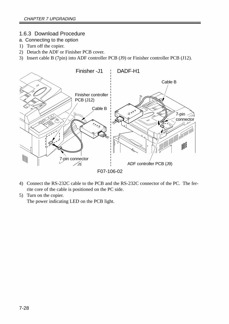
CHAPTER 7 UPGRADING
7-28
1.6.3 Download Procedurea. Connecting to the option1) Turn off the copier.2) Detach the ADF or Finisher PCB cover.3) Insert cable B (7pin) into ADF controller PCB (J9) or Finisher controller PCB (J12).
F07-106-02
4) Connect the RS-232C cable to the PCB and the RS-232C connector of the PC. The fer-rite core of the cable is positioned on the PC side.
5) Turn on the copier.The power indicating LED on the PCB light.
ADF controller PCB (J9)
DADF-H1
Cable B
Finisher controllerPCB (J12)
Finisher -J1
7-pin connector
7-pinconnector
Cable B
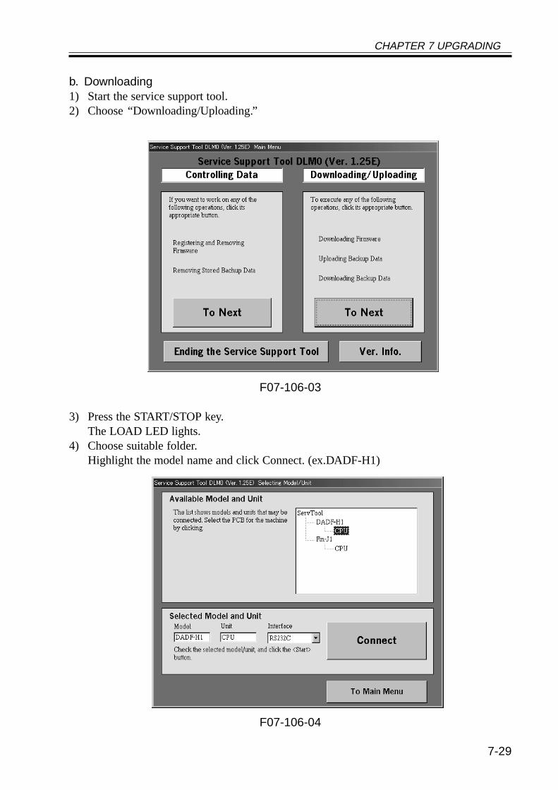
CHAPTER 7 UPGRADING
7-29
b. Downloading1) Start the service support tool.2) Choose “Downloading/Uploading.”
F07-106-03
3) Press the START/STOP key.The LOAD LED lights.
4) Choose suitable folder.Highlight the model name and click Connect. (ex.DADF-H1)
F07-106-04
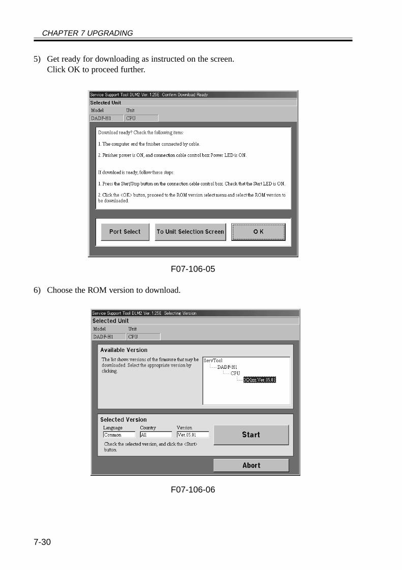
CHAPTER 7 UPGRADING
7-30
5) Get ready for downloading as instructed on the screen.Click OK to proceed further.
F07-106-05
6) Choose the ROM version to download.
F07-106-06
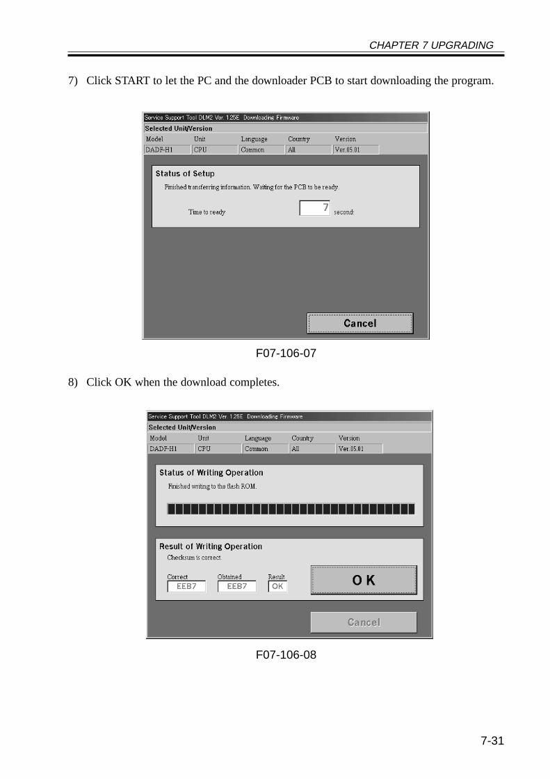
CHAPTER 7 UPGRADING
7-31
7) Click START to let the PC and the downloader PCB to start downloading the program.
F07-106-07
8) Click OK when the download completes.
F07-106-08
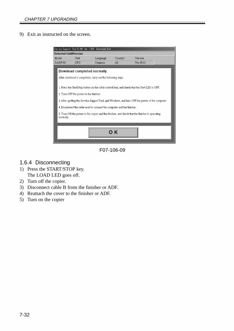
CHAPTER 7 UPGRADING
7-32
9) Exit as instructed on the screen.
F07-106-09
1.6.4 Disconnecting1) Press the START/STOP key.
The LOAD LED goes off.2) Turn off the copier.3) Disconnect cable B from the finisher or ADF.4) Reattach the cover to the finisher or ADF.5) Turn on the copier
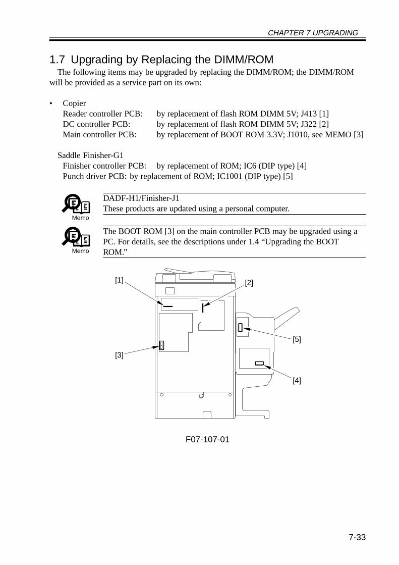
CHAPTER 7 UPGRADING
7-33
1.7 Upgrading by Replacing the DIMM/ROMThe following items may be upgraded by replacing the DIMM/ROM; the DIMM/ROM
will be provided as a service part on its own:
• CopierReader controller PCB: by replacement of flash ROM DIMM 5V; J413 [1]DC controller PCB: by replacement of flash ROM DIMM 5V; J322 [2]Main controller PCB: by replacement of BOOT ROM 3.3V; J1010, see MEMO [3]
Saddle Finisher-G1Finisher controller PCB: by replacement of ROM; IC6 (DIP type) [4]Punch driver PCB: by replacement of ROM; IC1001 (DIP type) [5]
Memo
DADF-H1/Finisher-J1These products are updated using a personal computer.
Memo
The BOOT ROM [3] on the main controller PCB may be upgraded using aPC. For details, see the descriptions under 1.4 “Upgrading the BOOTROM.”
F07-107-01
[1]
[3]
[5]
[4]
[2]
CHAPTER 7 UPGRADING
7-34
2 Backing Up Data
2.1 OutlineUsing the Service Support Tool, you can back up the data of the SRAM mounted to the
main controller PCB.The SRAM contains the following items of data:
• Service mode settings• User mode settings• Various MACHINE DATA
Once you have backed up the data, you may write it to the main controller PCB after re-placing the PCB; or, you can simplify the work involved in entering service mode or usermode settings.
It is recommended to back up the data whenever possible using the Service Support Toolwhen you have updated the service mode settings or the user mode settings.
CHAPTER 7 UPGRADING
7-35
2.2 Backing Up Data2.2.1 Making Preparations• Install the system software to the Service Support Tool, making sure that its version is
the same as that of the machine in question.• Check to make sure that the machine’s Data lamp is OFF.• Turn off the machine’s main power switch, and disconnect the power plug; as necessary,
disconnect the network cable.
2.2.2 Making ConnectionsThe discussions that follow assume the use of a parallel cable:
1) Using a parallel cable, connect the PC to the parallel connector on the right side of thecontroller.
• At this time, the PC must remain OFF.• Connect the 25-point connector of the parallel cable to the PC and the 36-pin connector
to the machine.2) Turn on the power switch of the PC, and start up the Service Support Tool.3) Connect the machine’s power plug to the power outlet, and turn on its main power
switch.4) Start service mode.5) Make the following selections so that the machine will enter download standby mode
(notation “STNDBY”): COPIER>FUNCTION>SYSTEM>DOWNLOAD.
Memo
You can select ‘network’ as the interface for data backup. Here, the use of abi-Centronics cable is assumed.
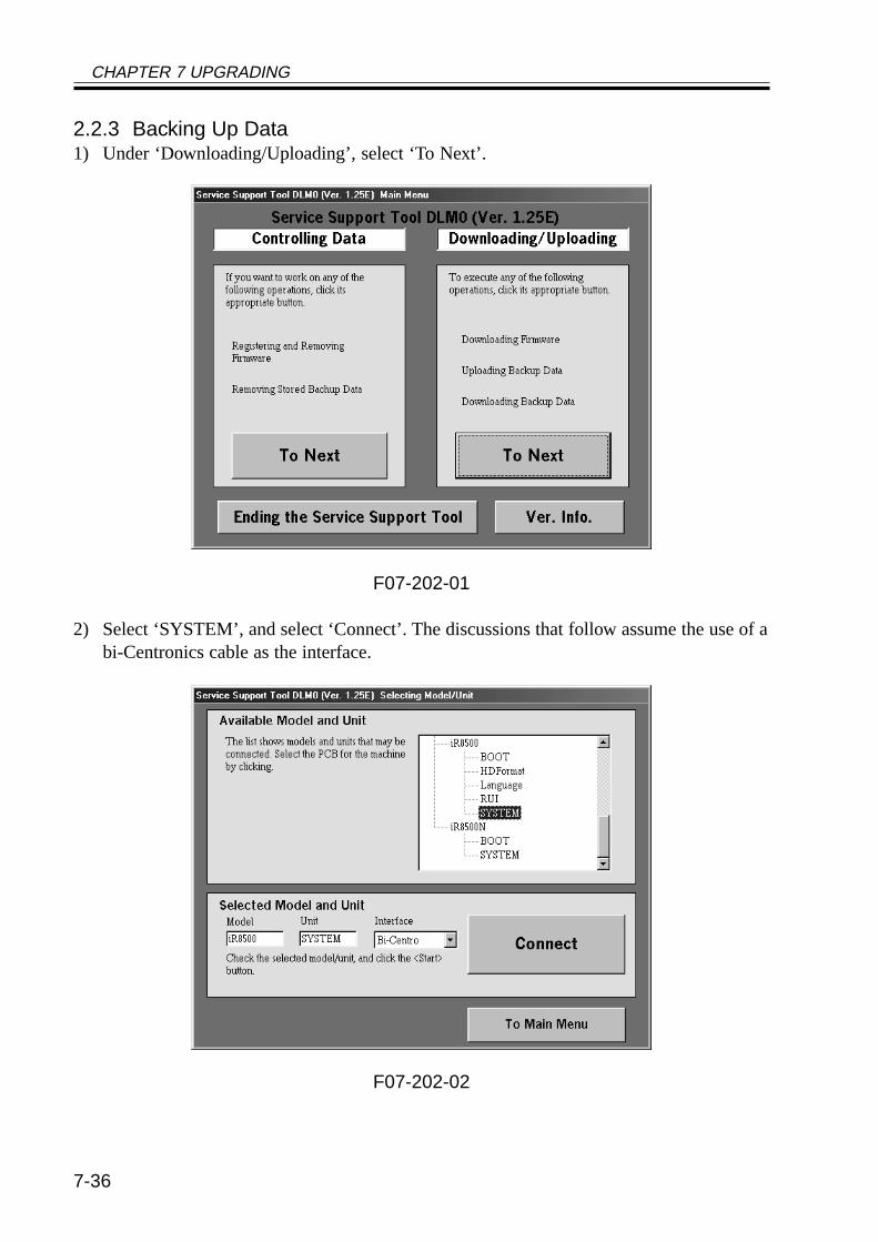
CHAPTER 7 UPGRADING
7-36
2.2.3 Backing Up Data1) Under ‘Downloading/Uploading’, select ‘To Next’.
F07-202-01
2) Select ‘SYSTEM’, and select ‘Connect’. The discussions that follow assume the use of abi-Centronics cable as the interface.
F07-202-02
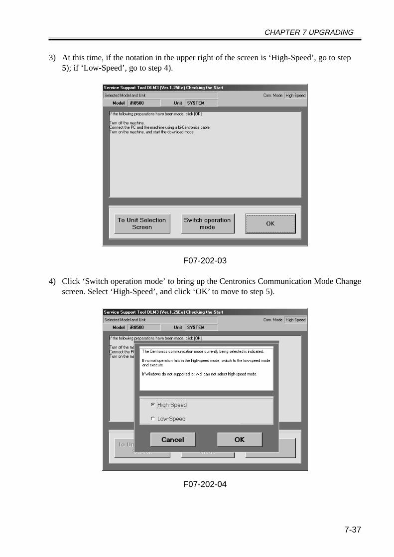
CHAPTER 7 UPGRADING
7-37
3) At this time, if the notation in the upper right of the screen is ‘High-Speed’, go to step5); if ‘Low-Speed’, go to step 4).
F07-202-03
4) Click ‘Switch operation mode’ to bring up the Centronics Communication Mode Changescreen. Select ‘High-Speed’, and click ‘OK’ to move to step 5).
F07-202-04
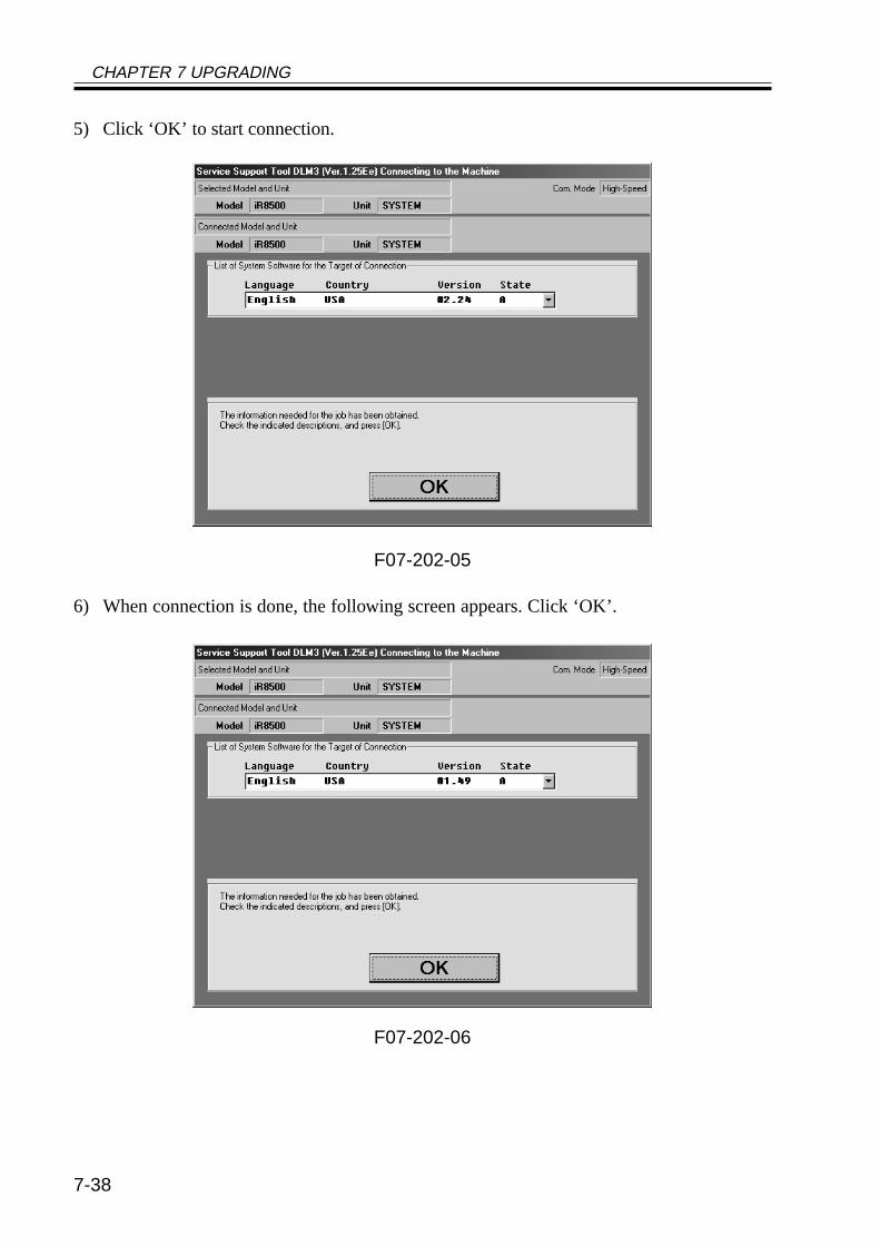
CHAPTER 7 UPGRADING
7-38
5) Click ‘OK’ to start connection.
F07-202-05
6) When connection is done, the following screen appears. Click ‘OK’.
F07-202-06
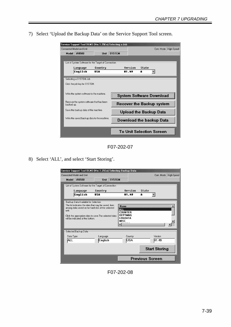
CHAPTER 7 UPGRADING
7-39
7) Select ‘Upload the Backup Data’ on the Service Support Tool screen.
F07-202-07
8) Select ‘ALL’, and select ‘Start Storing’.
F07-202-08
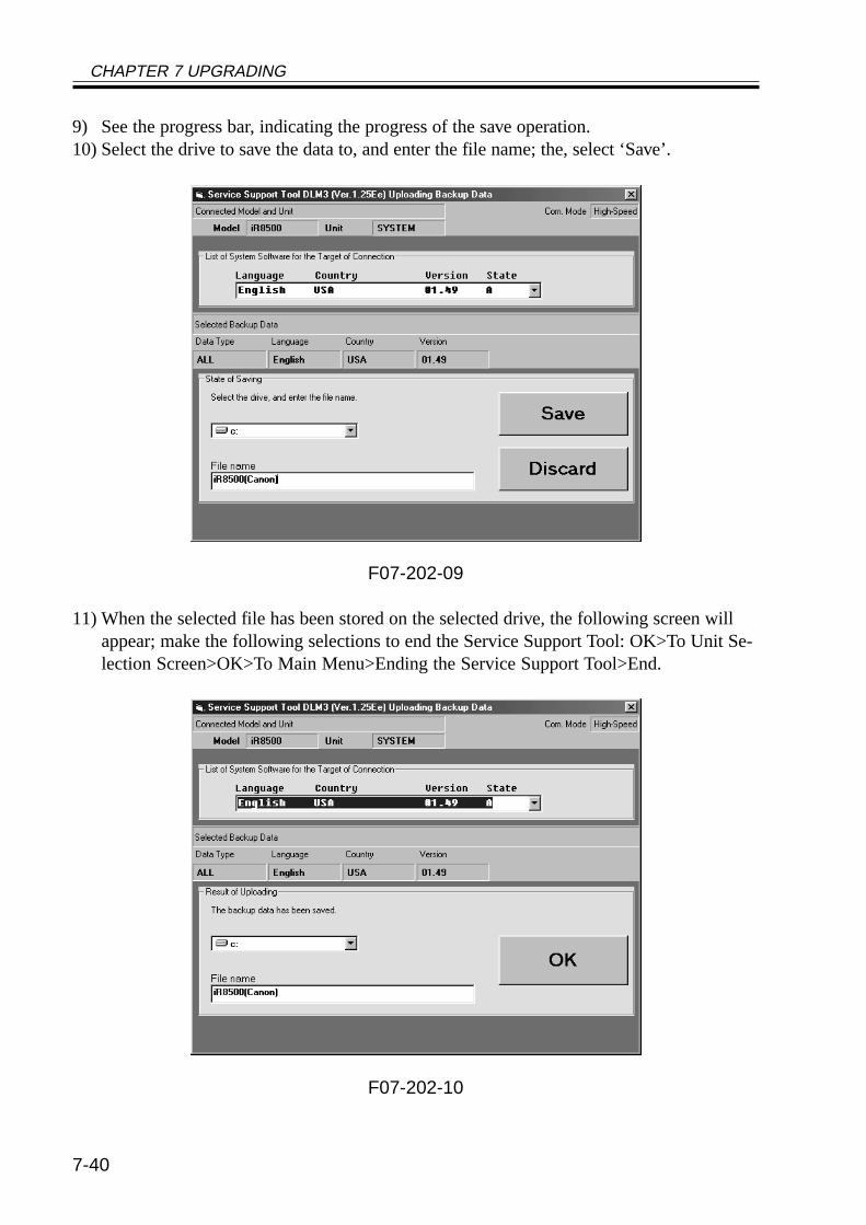
CHAPTER 7 UPGRADING
7-40
9) See the progress bar, indicating the progress of the save operation.10) Select the drive to save the data to, and enter the file name; the, select ‘Save’.
F07-202-09
11) When the selected file has been stored on the selected drive, the following screen willappear; make the following selections to end the Service Support Tool: OK>To Unit Se-lection Screen>OK>To Main Menu>Ending the Service Support Tool>End.
F07-202-10
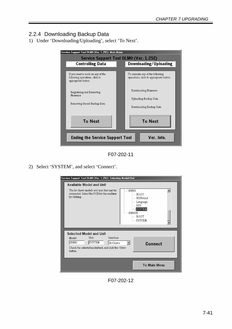
CHAPTER 7 UPGRADING
7-41
2.2.4 Downloading Backup Data1) Under ‘Downloading/Uploading’, select ‘To Next’.
F07-202-11
2) Select ‘SYSTEM’, and select ‘Connect’.
F07-202-12
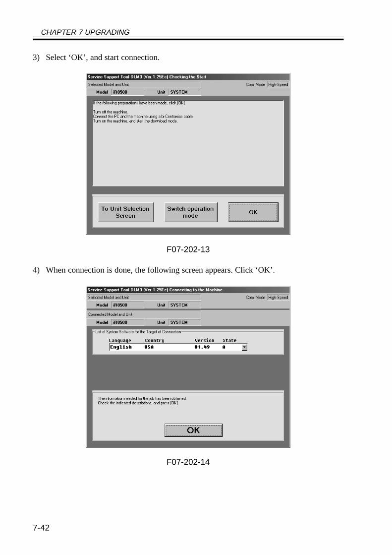
CHAPTER 7 UPGRADING
7-42
3) Select ‘OK’, and start connection.
F07-202-13
4) When connection is done, the following screen appears. Click ‘OK’.
F07-202-14
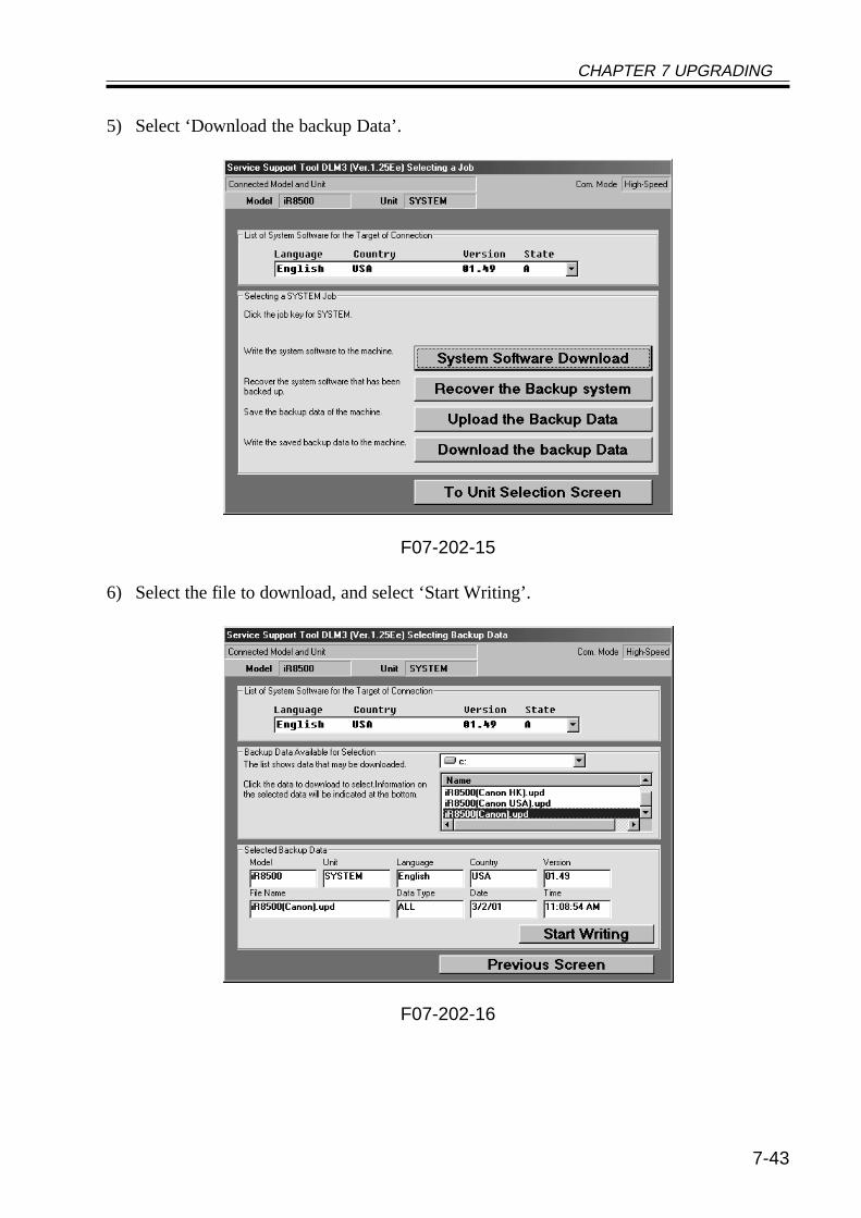
CHAPTER 7 UPGRADING
7-43
5) Select ‘Download the backup Data’.
F07-202-15
6) Select the file to download, and select ‘Start Writing’.
F07-202-16
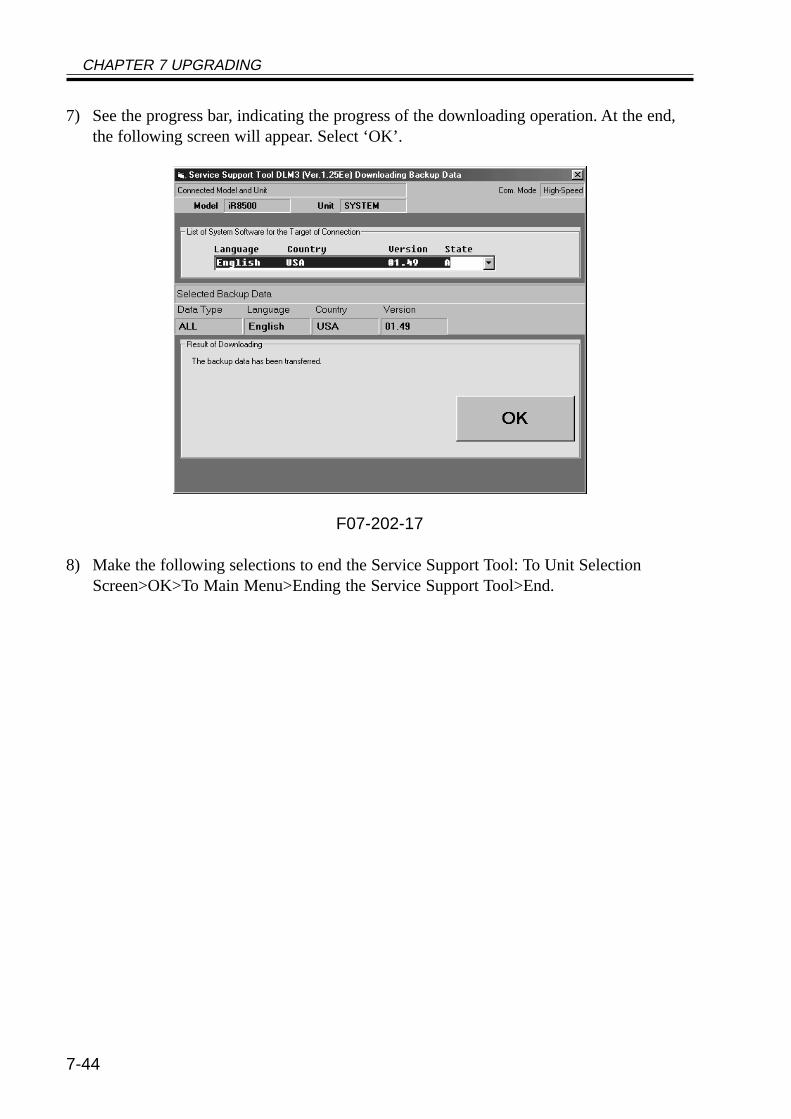
CHAPTER 7 UPGRADING
7-44
7) See the progress bar, indicating the progress of the downloading operation. At the end,the following screen will appear. Select ‘OK’.
F07-202-17
8) Make the following selections to end the Service Support Tool: To Unit SelectionScreen>OK>To Main Menu>Ending the Service Support Tool>End.
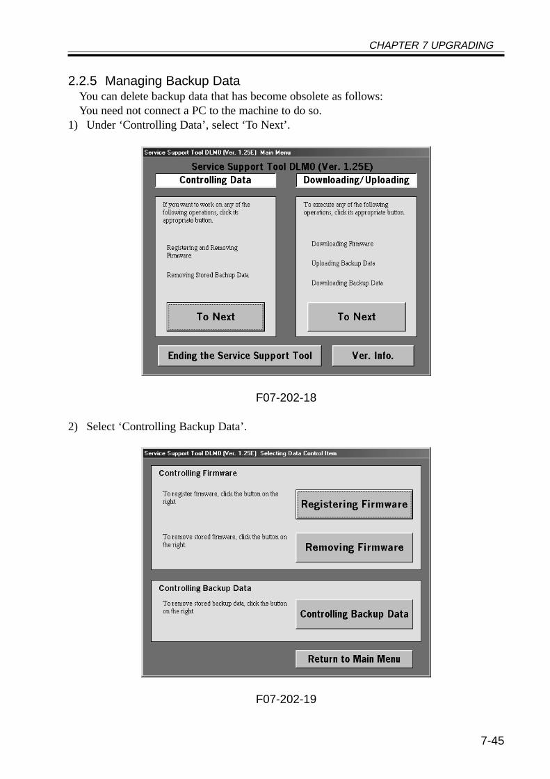
CHAPTER 7 UPGRADING
7-45
2.2.5 Managing Backup DataYou can delete backup data that has become obsolete as follows:You need not connect a PC to the machine to do so.
1) Under ‘Controlling Data’, select ‘To Next’.
F07-202-18
2) Select ‘Controlling Backup Data’.
F07-202-19
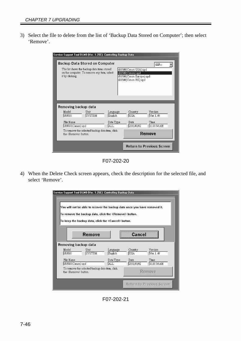
CHAPTER 7 UPGRADING
7-46
3) Select the file to delete from the list of ‘Backup Data Stored on Computer’; then select‘Remove’.
F07-202-20
4) When the Delete Check screen appears, check the description for the selected file, andselect ‘Remove’.
F07-202-21
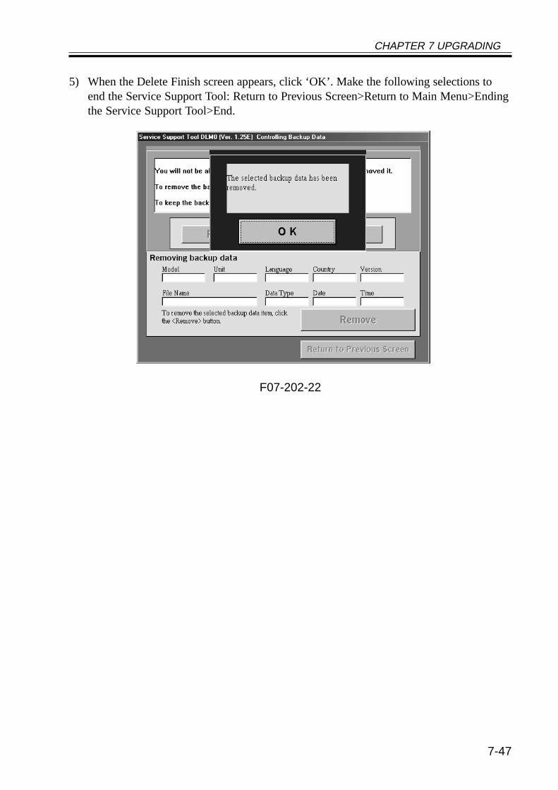
CHAPTER 7 UPGRADING
7-47
5) When the Delete Finish screen appears, click ‘OK’. Make the following selections toend the Service Support Tool: Return to Previous Screen>Return to Main Menu>Endingthe Service Support Tool>End.
F07-202-22

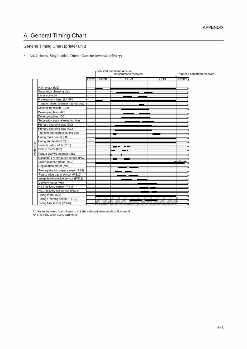
A-1
A. General Timing Chart
General Timing Chart (printer unit)
• A4, 2 sheets, Single-sided, Direct, Cassette (reversal delivery)
Main motor (M1)
Developing bias (DC)Separation static eliminating bias
Pre-exposure lamp (LAMP2)Transfer sheet-to-sheet interval biasDeveloping clutch (CL3)
Developing bias (AC)
Primary charging bias (DC)Primary charging bias (AC)
Separation charging bias
Transfer changing cleaning bias
Fixing main heater (H1)
Laser activation
Pickup motor (M2)
Pickup DOWN solenoid (SL1)Cassette 1 re-try paper sensor (PS7)
Registration motor (M9)Laser scanner motor (M10)
Registration paper sensor (PS10)Image leading edge sensor (PS12)
Fixing / feeding sensor (PS13)
Vertical path clutch (CL1)
Pre-registration paper sensor (PS9)
No.1 delivery sensor (PS15)No.1 delivery full sensor (PS16)Fixing motor (M4)
Fixing film sensor (PS26)
Delivery motor (M5)
Prin
ter
Uni
t
PSTBY PINTR PRINT LSTR PSTBY
Print command receivedJob start command received
Print end command received
Fixing sub heater(H2)
*2
*1
*1: Varies between 0 and 9 min to suit the selected silent mode shift interval.*2: Goes ON once every 540 msec.
APPENDIX
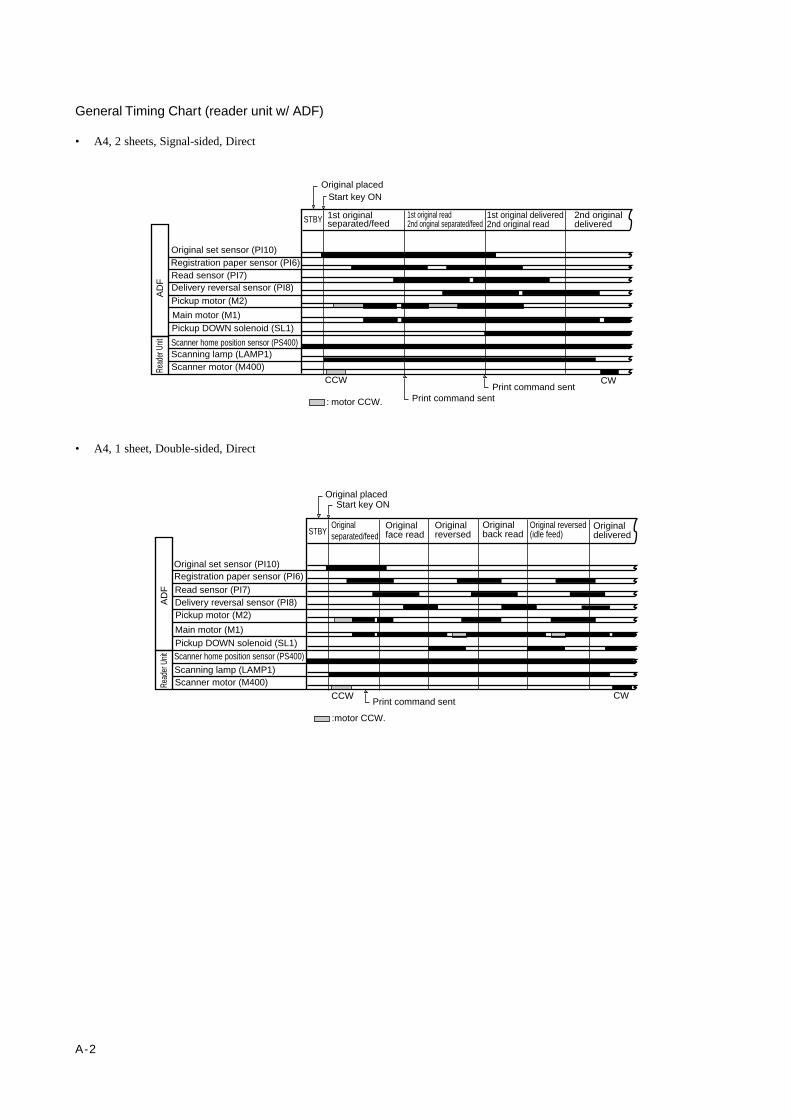
A-2
General Timing Chart (reader unit w/ ADF)
• A4, 2 sheets, Signal-sided, Direct
• A4, 1 sheet, Double-sided, Direct
Read
er U
nitA
DF
STBY
Original set sensor (PI10)Registration paper sensor (PI6)Read sensor (PI7)Delivery reversal sensor (PI8)
Pickup motor (M2)
Main motor (M1)Pickup DOWN solenoid (SL1)
Original placed
1st originalseparated/feed
1st original read2nd original separated/feed
1st original delivered2nd original read
2nd originaldelivered
Scanner home position sensor (PS400)Scanning lamp (LAMP1)Scanner motor (M400)
CCW CW
Start key ON
Print command sentPrint command sent
: motor CCW.
Read
er U
nitA
DF
STBY
Original set sensor (PI10)Registration paper sensor (PI6)
Read sensor (PI7)Delivery reversal sensor (PI8)Pickup motor (M2)
Main motor (M1)Pickup DOWN solenoid (SL1)
Original placed
Originalseparated/feed
Originalface read
Originalreversed
Original reversed(idle feed)
Scanner home position sensor (PS400)
Scanning lamp (LAMP1)Scanner motor (M400)
CCW CW
Start key ON
Print command sent
Originaldelivered
:motor CCW.
Originalback read
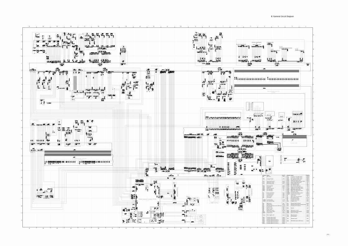
A-3
B. General Circuit Diagram
N
M
L
K
J
I
H
G
F
E
D
C
B
A
N
M
L
K
J
I
H
G
F
E
D
C
B
A
12345678912 11131415161718192021 10
12345678912 11131415161718192021 10
0VA
13V
U
0VD 5V
0VU
3
0VU
3
24V
U3
24V
U3
24
V
24
V
24
V
J3086
LAMP 1
24V
U3
0VU
3
13V
U3
0VA 5V
0VD
J4101F
24V
HTTRG1_ON
HTTRG2_ON
HTRLY_ON
(Fro
m 3
-M)
H5
H4
5V GN
D
AP
ON
J 3 0 8 8
J3126
J320
0M
To Super G4 FAX Board-B1
Off-hookdetection PCB
To FAX Unit
To FAX Unit
To FAX Unit
NameBD sensor
Leakage breaker
Vertical path clutchMultifeeder clutchDeveloping clutch
Developing fanFixing fanElectrical unit fanCarl reducing 1Carl reducing 2
Fixing main heaterFixing sub heaterCassette heaterMirror heaterLens heater
Scanning lampPre-exposure lamp
Main motorPickup motorHorizontal registration sensor shift motorFixing motorDelivery motorDuplex motorRegistration motorLaser scanner motorScanner moter
Power supply cord
Cassette1 paper sensorCassette2 paper sensorCassette1 paper level sensor 1Cassette1 paper level sensor 2Cassette2 paper level sensor 1Cassette2 paper level sensor 2
Position13-K
14-A
20-N18-N20-J
18-N18-J2-H7-I7-I
9-C9-B9-B9-A9-A
17-H14-J
20-I20-N17-N15-J9-N8-N
14-M14-J18-G
14-A
19-N19-M20-M20-M20-M20-M
NotaionBD
CB1
CL1CL2CL3
FM1FM2FM3FM4FM5
H1H2H3H4H5
LAMP1LAMP2
M1M2M3M4M5M6M9M10M400
PLG1
PS1PS2PS3PS4PS5PS6
NameCassette1 re-try paper sensorCassette2 re-try paper sensorPre-registration paper sensorRegistration paper sensorHorizontal registration paper sensorImage leading edge sensorFixing/feeding sensorNo.1 delivery sensorNo.1 delivery full sensorDuplex unit inlet paper sensorDuplex unit outlet paper sensorMultifeeder paper sensorRight cover open/close sensorFixing film sensorScanner home position sensorCopyboard cover sensorToner sensorWaste toner case full sensorEnvironment sensorCassette1 size sensorCassette2 size sensorOriginal sensor
Pickup DOWN solenoidMultifeeder holding plate releasing solenoidCharging roller solenoid
Speaker
Main power switchEnvironment heater switchFront cover switch
Main thermisterSub thermister
Thermal switch
Multifeeder paper width sensor
Position20-M20-M16-N16-N16-N16-I8-J8-N9-N7-N7-N
15-N15-N8-J
18-H17-H18-N6-I
17-N17-J16-J19-H
20-N20-J20-J
1-E
12-B12-B14-B
12-J12-J
9-B
18-M
NotationPS7PS8PS9PS10PS11PS12PS13PS15PS16PS17PS18PS22PS23PS26PS400PS401S1S2S3S4S5SD1
SL1SL5SL6
SP1
SW1SW2SW3
TH1TH2
TP1
VR1
Composite power supply PCB
Main power supply PCB
Switch PCB
Accessoriespower supply PCB
DC controller PCB
Thermistor separation powersupply PCB (200V model only)
Reader controller PCB
Pickup PCB
Laser driver PCB
Control Panel PCB
CCD PCB
Inverter PCB
( 1 0 0 V O N LY )
Main controller PCB (1/2)<U1000>
To DADF-H1
To 2-Cassette F
eeding Unit-W
1
To FAX Unit
Fixing Unit
<INV1>Inverter
PCB
To Side P
aper Deck-L1
To Finisher-J1
To S
addl
e F
inis
her-
G1
(Fro
m 3
-M)
(Fro
m 1
-M)
Counter PCB
Software ID PCB
Centronics PCB
To Inner 2-way Tray-A1
To Inner 2-way Tray-A1 or
Relay delivery unit
To Delivery Unit
To 6-C(Side Paper Deck-L1)
To 12-C(2-Cassette Feeding Unit-W1)
To 6-B(Saddle Finisher-G1)
Main controller PCB (2/2)<U1000>
HDD (2.5INCH) CC-IV N
(accessory)
(accessory)
(accessory)
From FA
X U
nit

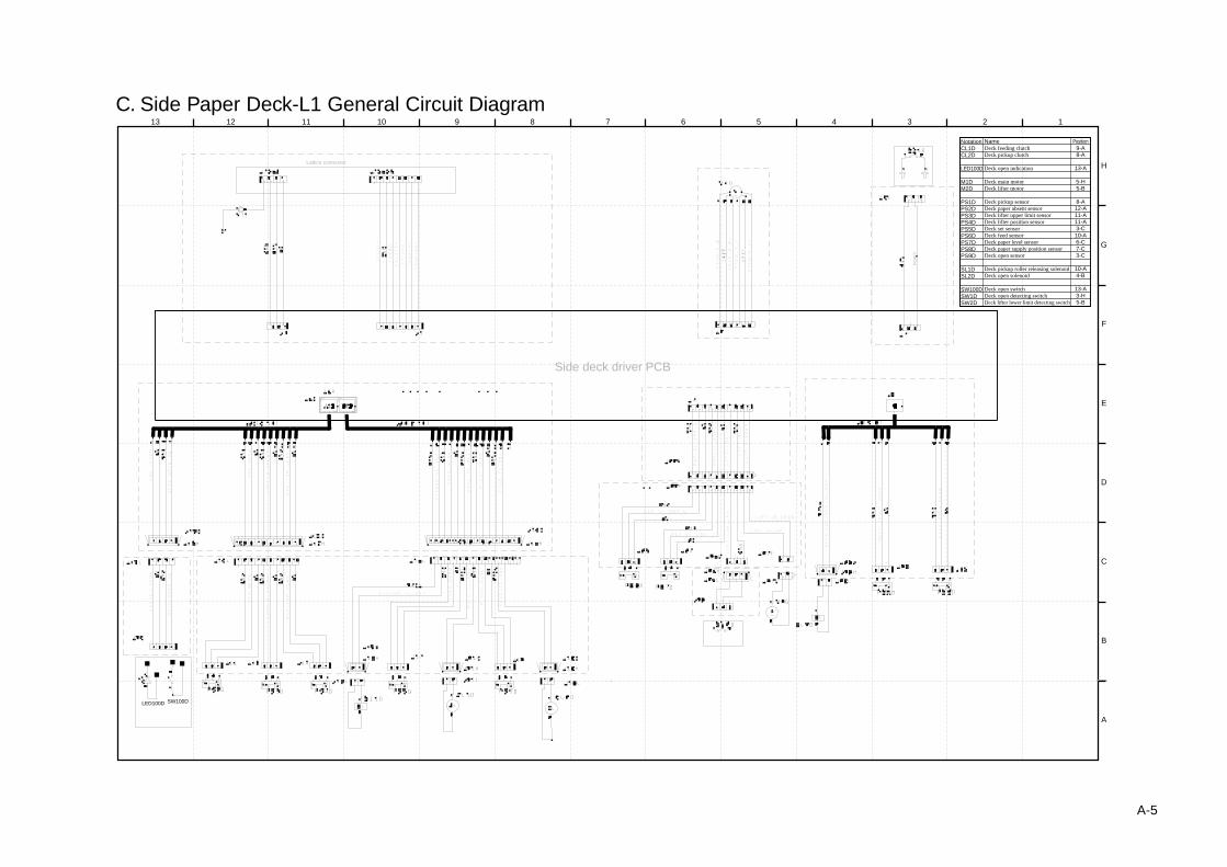
A-5
13 12 11 10 9 8 7 6 5 4 3 2 1
H
G
F
E
D
C
B
A
LED100D SW100D
PO
PD
*
Side deck driver PCB
Lattice connector
NameDeck feeding clutchDeck pickup clutch
Deck open indication
Deck main motorDeck lifter motor
Deck pickup sensorDeck paper absent sensorDeck lifter upper limit sensorDeck lifter position sensorDeck set sensorDeck feed sensorDeck paper level sensorDeck paper supply position sensorDeck open sensor
Deck pickup roller releasing solenoidDeck open solenoid
Deck open switchDeck open detecting switchDeck lifter lower limit detecting switch
Position9-A8-A
13-A
5-H5-B
8-A12-A11-A11-A3-C10-A6-C7-C3-C
10-A4-B
13-A3-H5-B
NotationCL1DCL2D
LED100D
M1DM2D
PS1DPS2DPS3DPS4DPS5DPS6DPS7DPS8DPS9D
SL1DSL2D
SW100DSW1DSW2D
C. Side Paper Deck-L1 General Circuit Diagram
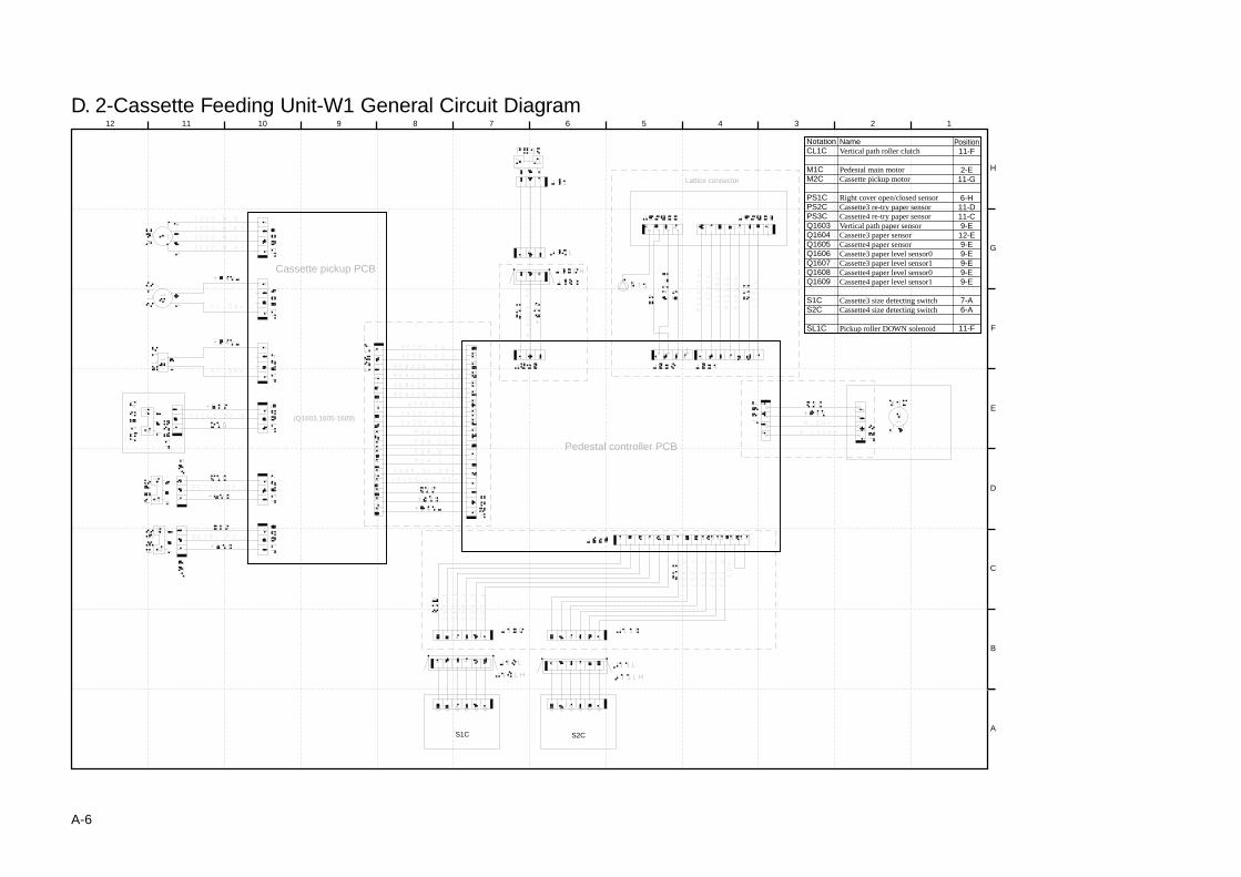
A-6
D. 2-Cassette Feeding Unit-W1 General Circuit Diagram12 11 10 9 8 7 6 5 4 3 2 1
H
G
F
E
D
C
B
AS1C S2C
(Q1603,1605-1609)
Lattice connector
Cassette pickup PCB
Pedestal controller PCB
NameVertical path roller clutch
Pedestal main motorCassette pickup motor
Right cover open/closed sensorCassette3 re-try paper sensorCassette4 re-try paper sensorVertical path paper sensorCassette3 paper sensorCassette4 paper sensorCassette3 paper level sensor0Cassette3 paper level sensor1Cassette4 paper level sensor0Cassette4 paper level sensor1
Cassette3 size detecting switchCassette4 size detecting switch
Pickup roller DOWN solenoid
Position11-F
2-E11-G
6-H11-D11-C9-E12-E9-E9-E9-E9-E9-E
7-A6-A
11-F
NotationCL1C
M1CM2C
PS1CPS2CPS3CQ1603Q1604Q1605Q1606Q1607Q1608Q1609
S1CS2C
SL1C
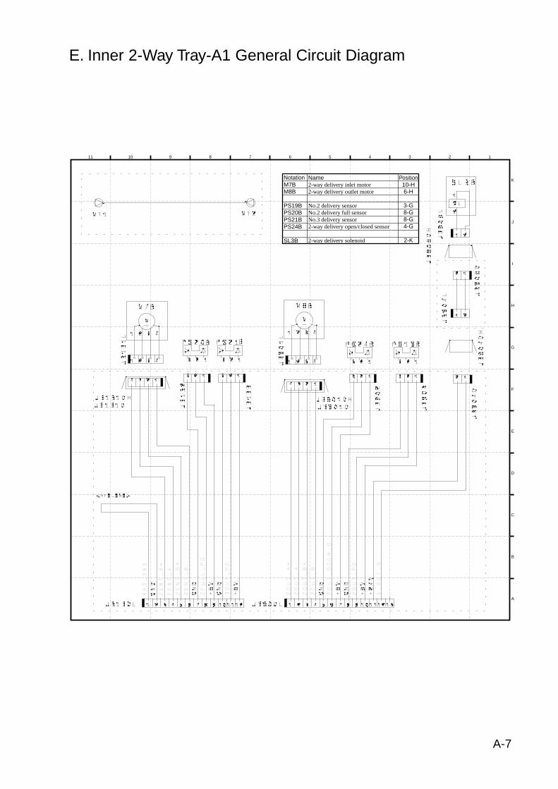
A-7
E. Inner 2-Way Tray-A1 General Circuit Diagram
11 10 9 8 7 6 5 4 3 2 1
H
I
J
K
G
F
E
D
C
B
A
Name2-way delivery inlet motor2-way delivery outlet motor
No.2 delivery sensorNo.2 delivery full sensorNo.3 delivery sensor2-way delivery open/closed sensor
2-way delivery solenoid
Position10-H6-H
3-G8-G8-G4-G
2-K
NotationM7BM8B
PS19BPS20BPS21BPS24B
SL3B
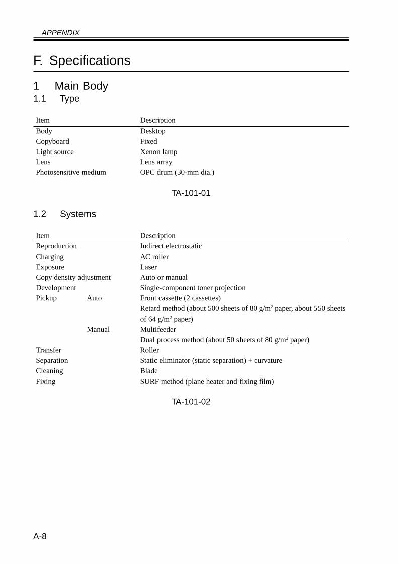
APPENDIX
A-8
F. Specifications
1 Main Body1.1 Type
Item DescriptionBody DesktopCopyboard FixedLight source Xenon lampLens Lens arrayPhotosensitive medium OPC drum (30-mm dia.)
TA-101-01
1.2 Systems
Item DescriptionReproduction Indirect electrostaticCharging AC rollerExposure LaserCopy density adjustment Auto or manualDevelopment Single-component toner projectionPickup Auto Front cassette (2 cassettes)
Retard method (about 500 sheets of 80 g/m2 paper, about 550 sheetsof 64 g/m2 paper)
Manual MultifeederDual process method (about 50 sheets of 80 g/m2 paper)
Transfer RollerSeparation Static eliminator (static separation) + curvatureCleaning BladeFixing SURF method (plane heater and fixing film)
TA-101-02
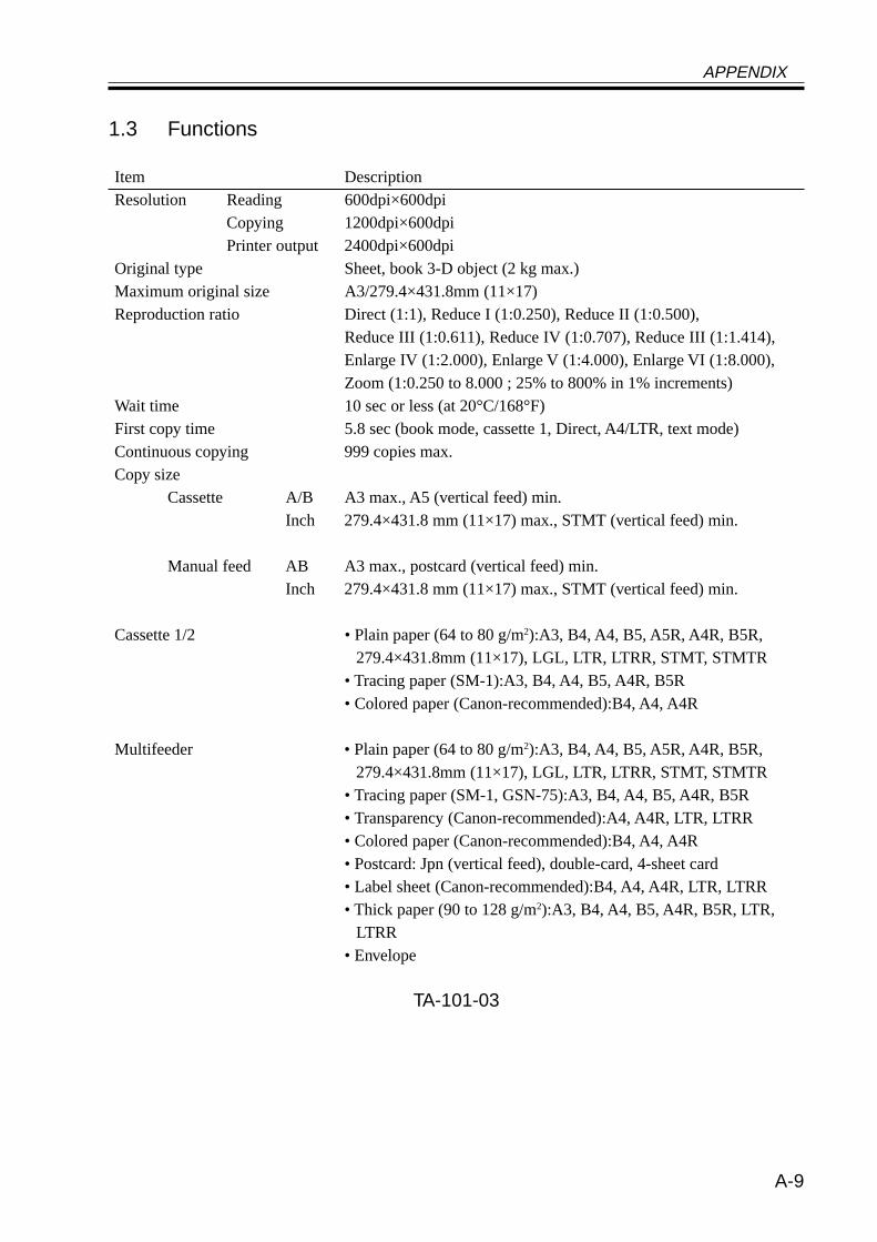
APPENDIX
A-9
1.3 Functions
Item DescriptionResolution Reading 600dpi×600dpi
Copying 1200dpi×600dpiPrinter output 2400dpi×600dpi
Original type Sheet, book 3-D object (2 kg max.)Maximum original size A3/279.4×431.8mm (11×17)Reproduction ratio Direct (1:1), Reduce I (1:0.250), Reduce II (1:0.500),
Reduce III (1:0.611), Reduce IV (1:0.707), Reduce III (1:1.414),Enlarge IV (1:2.000), Enlarge V (1:4.000), Enlarge VI (1:8.000),Zoom (1:0.250 to 8.000 ; 25% to 800% in 1% increments)
Wait time 10 sec or less (at 20°C/168°F)First copy time 5.8 sec (book mode, cassette 1, Direct, A4/LTR, text mode)Continuous copying 999 copies max.Copy size
Cassette A/B A3 max., A5 (vertical feed) min.Inch 279.4×431.8 mm (11×17) max., STMT (vertical feed) min.
Manual feed AB A3 max., postcard (vertical feed) min.Inch 279.4×431.8 mm (11×17) max., STMT (vertical feed) min.
Cassette 1/2 • Plain paper (64 to 80 g/m2):A3, B4, A4, B5, A5R, A4R, B5R,279.4×431.8mm (11×17), LGL, LTR, LTRR, STMT, STMTR
• Tracing paper (SM-1):A3, B4, A4, B5, A4R, B5R• Colored paper (Canon-recommended):B4, A4, A4R
Multifeeder • Plain paper (64 to 80 g/m2):A3, B4, A4, B5, A5R, A4R, B5R,279.4×431.8mm (11×17), LGL, LTR, LTRR, STMT, STMTR
• Tracing paper (SM-1, GSN-75):A3, B4, A4, B5, A4R, B5R• Transparency (Canon-recommended):A4, A4R, LTR, LTRR• Colored paper (Canon-recommended):B4, A4, A4R• Postcard: Jpn (vertical feed), double-card, 4-sheet card• Label sheet (Canon-recommended):B4, A4, A4R, LTR, LTRR• Thick paper (90 to 128 g/m2):A3, B4, A4, B5, A4R, B5R, LTR,
LTRR• Envelope
TA-101-03
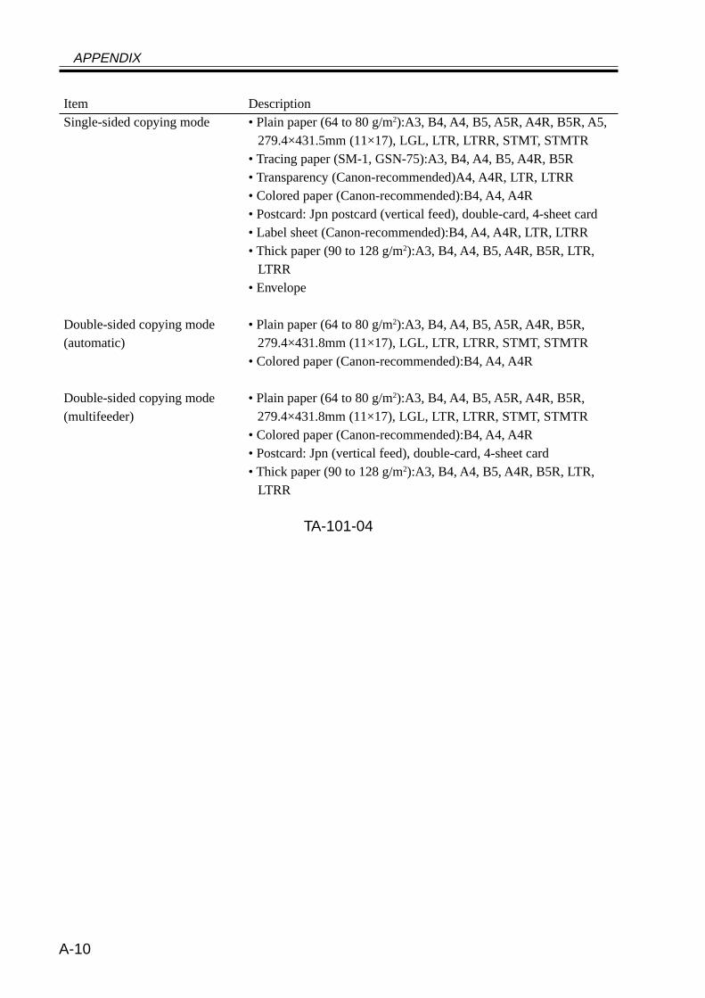
APPENDIX
A-10
Item DescriptionSingle-sided copying mode • Plain paper (64 to 80 g/m2):A3, B4, A4, B5, A5R, A4R, B5R, A5,
279.4×431.5mm (11×17), LGL, LTR, LTRR, STMT, STMTR• Tracing paper (SM-1, GSN-75):A3, B4, A4, B5, A4R, B5R• Transparency (Canon-recommended)A4, A4R, LTR, LTRR• Colored paper (Canon-recommended):B4, A4, A4R• Postcard: Jpn postcard (vertical feed), double-card, 4-sheet card• Label sheet (Canon-recommended):B4, A4, A4R, LTR, LTRR• Thick paper (90 to 128 g/m2):A3, B4, A4, B5, A4R, B5R, LTR,
LTRR• Envelope
Double-sided copying mode • Plain paper (64 to 80 g/m2):A3, B4, A4, B5, A5R, A4R, B5R,(automatic) 279.4×431.8mm (11×17), LGL, LTR, LTRR, STMT, STMTR
• Colored paper (Canon-recommended):B4, A4, A4R
Double-sided copying mode • Plain paper (64 to 80 g/m2):A3, B4, A4, B5, A5R, A4R, B5R,(multifeeder) 279.4×431.8mm (11×17), LGL, LTR, LTRR, STMT, STMTR
• Colored paper (Canon-recommended):B4, A4, A4R• Postcard: Jpn (vertical feed), double-card, 4-sheet card• Thick paper (90 to 128 g/m2):A3, B4, A4, B5, A4R, B5R, LTR,
LTRR
TA-101-04
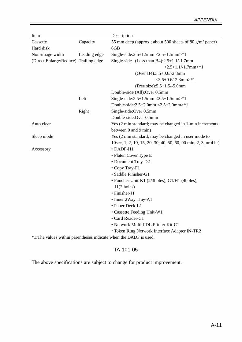
APPENDIX
A-11
Item DescriptionCassette Capacity 55 mm deep (approx.; about 500 sheets of 80 g/m2 paper)Hard disk 6GBNon-image width Leading edge Single-side:2.5±1.5mm <2.5±1.5mm>*1(Direct,Enlarge/Reduce) Trailing edge Single-side (Less than B4):2.5+1.1/-1.7mm
<2.5+1.1/-1.7mm>*1(Over B4):3.5+0.6/-2.8mm
<3.5+0.6/-2.8mm>*1(Free size):5.5+1.5/-5.0mm
Double-side (All):Over 0.5mmLeft Single-side:2.5±1.5mm <2.5±1.5mm>*1
Double-side:2.5±2.0mm <2.5±2.0mm>*1Right Single-side:Over 0.5mm
Double-side:Over 0.5mmAuto clear Yes (2 min standard; may be changed in 1-min increments
between 0 and 9 min)Sleep mode Yes (2 min standard; may be changed in user mode to
10sec, 1, 2, 10, 15, 20, 30, 40, 50, 60, 90 min, 2, 3, or 4 hr)Accessory • DADF-H1
• Platen Cover Type E• Document Tray-D2• Copy Tray-F1• Saddle Finisher-G1• Puncher Unit-K1 (2/3holes), G1/H1 (4holes),
J1(2 holes)• Finisher-J1• Inner 2Way Tray-A1• Paper Deck-L1• Cassette Feeding Unit-W1• Card Reader-C1• Network Multi-PDL Printer Kit-C1• Token Ring Network Interface Adapter iN-TR2
*1:The values within parentheses indicate when the DADF is used.
TA-101-05
The above specifications are subject to change for product improvement.
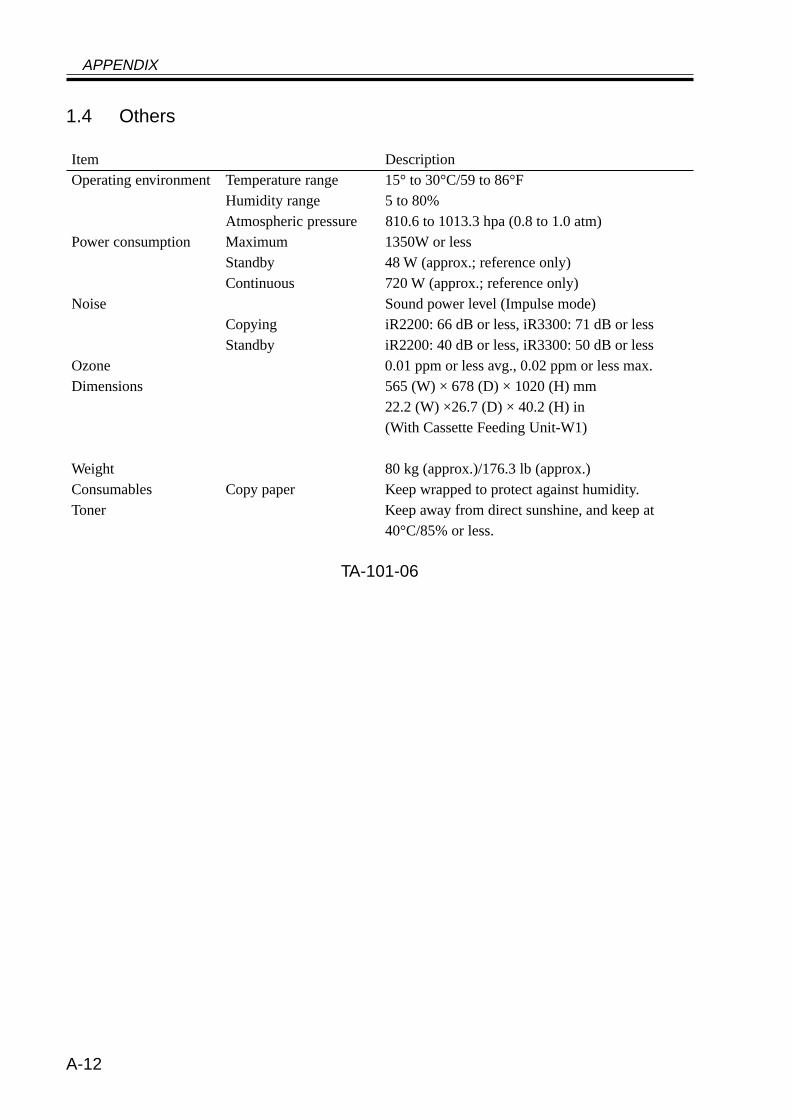
APPENDIX
A-12
1.4 Others
Item DescriptionOperating environment Temperature range 15° to 30°C/59 to 86°F
Humidity range 5 to 80%Atmospheric pressure 810.6 to 1013.3 hpa (0.8 to 1.0 atm)
Power consumption Maximum 1350W or lessStandby 48 W (approx.; reference only)Continuous 720 W (approx.; reference only)
Noise Sound power level (Impulse mode)Copying iR2200: 66 dB or less, iR3300: 71 dB or lessStandby iR2200: 40 dB or less, iR3300: 50 dB or less
Ozone 0.01 ppm or less avg., 0.02 ppm or less max.Dimensions 565 (W) × 678 (D) × 1020 (H) mm
22.2 (W) ×26.7 (D) × 40.2 (H) in(With Cassette Feeding Unit-W1)
Weight 80 kg (approx.)/176.3 lb (approx.)Consumables Copy paper Keep wrapped to protect against humidity.Toner Keep away from direct sunshine, and keep at
40°C/85% or less.
TA-101-06
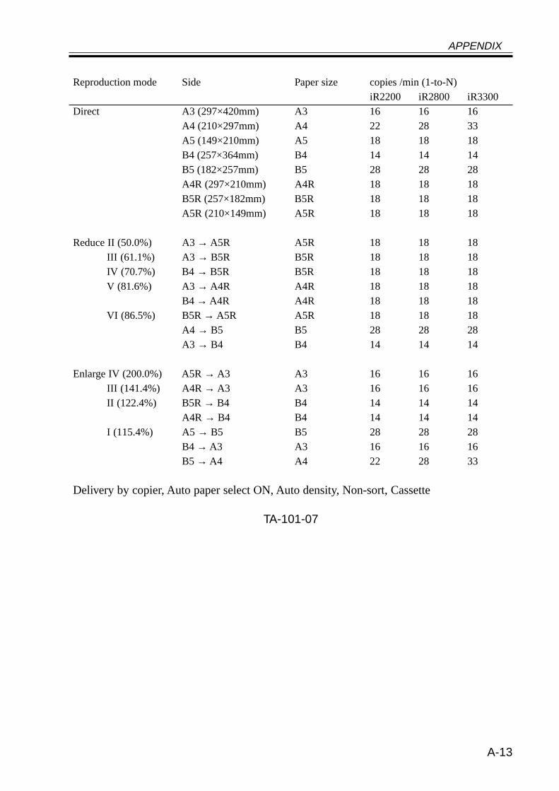
APPENDIX
A-13
Reproduction mode Side Paper size copies /min (1-to-N)iR2200 iR2800 iR3300
Direct A3 (297×420mm) A3 16 16 16A4 (210×297mm) A4 22 28 33A5 (149×210mm) A5 18 18 18B4 (257×364mm) B4 14 14 14B5 (182×257mm) B5 28 28 28A4R (297×210mm) A4R 18 18 18B5R (257×182mm) B5R 18 18 18A5R (210×149mm) A5R 18 18 18
Reduce II (50.0%) A3 → A5R A5R 18 18 18III (61.1%) A3 → B5R B5R 18 18 18IV (70.7%) B4 → B5R B5R 18 18 18V (81.6%) A3 → A4R A4R 18 18 18
B4 → A4R A4R 18 18 18VI (86.5%) B5R → A5R A5R 18 18 18
A4 → B5 B5 28 28 28A3 → B4 B4 14 14 14
Enlarge IV (200.0%) A5R → A3 A3 16 16 16III (141.4%) A4R → A3 A3 16 16 16II (122.4%) B5R → B4 B4 14 14 14
A4R → B4 B4 14 14 14I (115.4%) A5 → B5 B5 28 28 28
B4 → A3 A3 16 16 16B5 → A4 A4 22 28 33
Delivery by copier, Auto paper select ON, Auto density, Non-sort, Cassette
TA-101-07
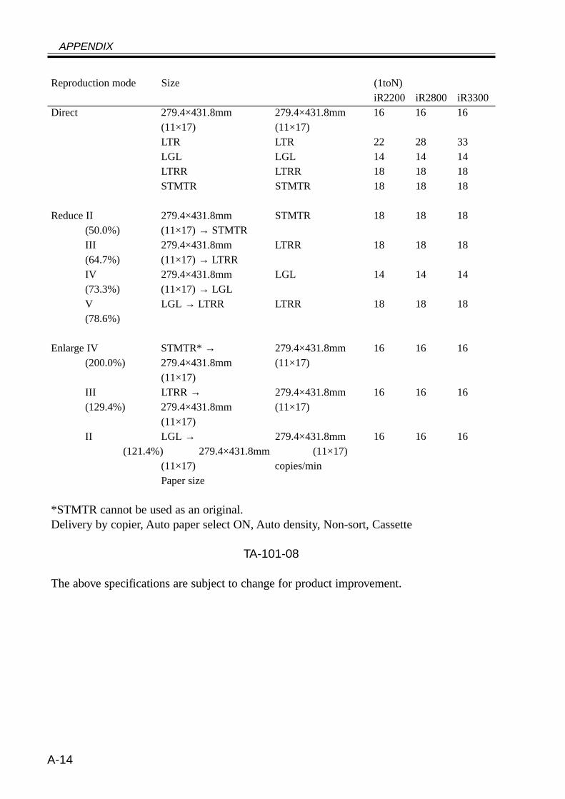
APPENDIX
A-14
Reproduction mode Size (1toN)iR2200 iR2800 iR3300
Direct 279.4×431.8mm 279.4×431.8mm 16 16 16(11×17) (11×17)LTR LTR 22 28 33LGL LGL 14 14 14LTRR LTRR 18 18 18STMTR STMTR 18 18 18
Reduce II 279.4×431.8mm STMTR 18 18 18(50.0%) (11×17) → STMTRIII 279.4×431.8mm LTRR 18 18 18(64.7%) (11×17) → LTRRIV 279.4×431.8mm LGL 14 14 14(73.3%) (11×17) → LGLV LGL → LTRR LTRR 18 18 18(78.6%)
Enlarge IV STMTR* → 279.4×431.8mm 16 16 16(200.0%) 279.4×431.8mm (11×17)
(11×17)III LTRR → 279.4×431.8mm 16 16 16(129.4%) 279.4×431.8mm (11×17)
(11×17)II LGL → 279.4×431.8mm 16 16 16
(121.4%) 279.4×431.8mm (11×17)(11×17) copies/minPaper size
*STMTR cannot be used as an original.Delivery by copier, Auto paper select ON, Auto density, Non-sort, Cassette
TA-101-08
The above specifications are subject to change for product improvement.
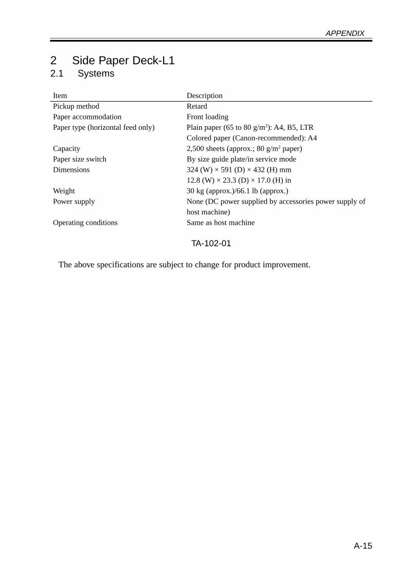
APPENDIX
A-15
2 Side Paper Deck-L12.1 Systems
Item DescriptionPickup method RetardPaper accommodation Front loadingPaper type (horizontal feed only) Plain paper (65 to 80 g/m2): A4, B5, LTR
Colored paper (Canon-recommended): A4Capacity 2,500 sheets (approx.; 80 g/m2 paper)Paper size switch By size guide plate/in service modeDimensions 324 (W) × 591 (D) × 432 (H) mm
12.8 (W) × 23.3 (D) × 17.0 (H) inWeight 30 kg (approx.)/66.1 lb (approx.)Power supply None (DC power supplied by accessories power supply of
host machine)Operating conditions Same as host machine
TA-102-01
The above specifications are subject to change for product improvement.
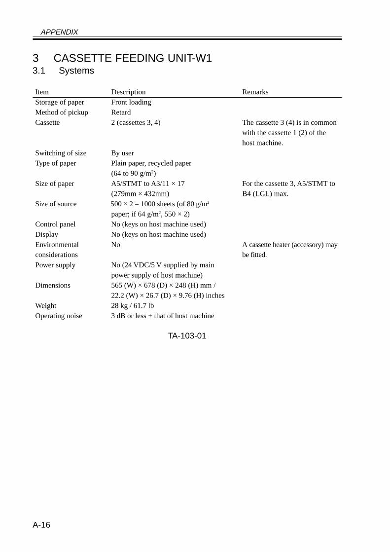
APPENDIX
A-16
3 CASSETTE FEEDING UNIT-W13.1 Systems
Item Description RemarksStorage of paper Front loadingMethod of pickup RetardCassette 2 (cassettes 3, 4) The cassette 3 (4) is in common
with the cassette 1 (2) of thehost machine.
Switching of size By userType of paper Plain paper, recycled paper
(64 to 90 g/m2)Size of paper A5/STMT to A3/11 × 17 For the cassette 3, A5/STMT to
(279mm × 432mm) B4 (LGL) max.Size of source 500 × 2 = 1000 sheets (of 80 g/m2
paper; if 64 g/m2, 550 × 2)Control panel No (keys on host machine used)Display No (keys on host machine used)Environmental No A cassette heater (accessory) mayconsiderations be fitted.Power supply No (24 VDC/5 V supplied by main
power supply of host machine)Dimensions 565 (W) × 678 (D) × 248 (H) mm /
22.2 (W) × 26.7 (D) × 9.76 (H) inchesWeight 28 kg / 61.7 lbOperating noise 3 dB or less + that of host machine
TA-103-01
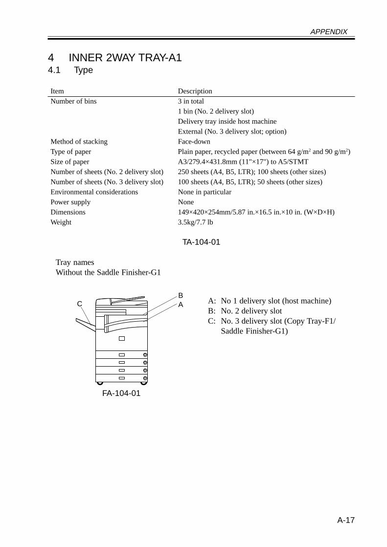
APPENDIX
A-17
4 INNER 2WAY TRAY-A14.1 Type
Item DescriptionNumber of bins 3 in total
1 bin (No. 2 delivery slot)Delivery tray inside host machineExternal (No. 3 delivery slot; option)
Method of stacking Face-downType of paper Plain paper, recycled paper (between 64 g/m2 and 90 g/m2)Size of paper A3/279.4×431.8mm (11"×17") to A5/STMTNumber of sheets (No. 2 delivery slot) 250 sheets (A4, B5, LTR); 100 sheets (other sizes)Number of sheets (No. 3 delivery slot) 100 sheets (A4, B5, LTR); 50 sheets (other sizes)Environmental considerations None in particularPower supply NoneDimensions 149×420×254mm/5.87 in.×16.5 in.×10 in. (W×D×H)Weight 3.5kg/7.7 lb
TA-104-01
Tray namesWithout the Saddle Finisher-G1
FA-104-01
C AB
A: No 1 delivery slot (host machine)B: No. 2 delivery slotC: No. 3 delivery slot (Copy Tray-F1/
Saddle Finisher-G1)
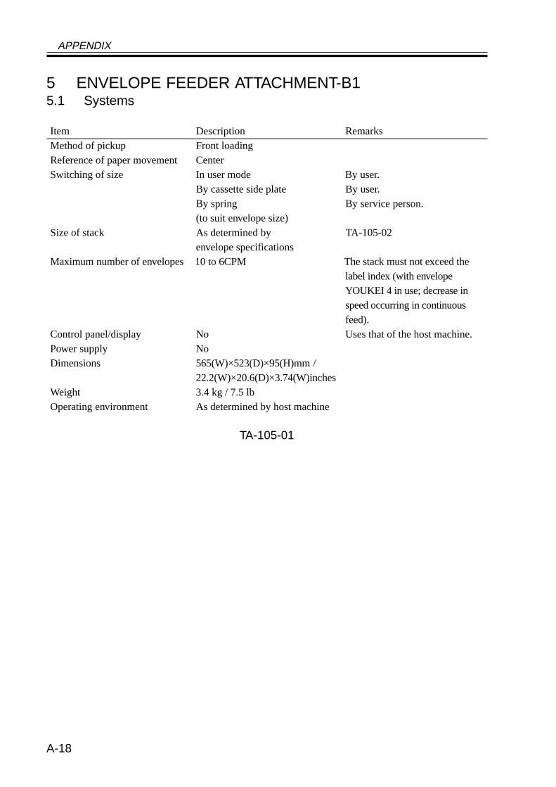
APPENDIX
A-18
5 ENVELOPE FEEDER ATTACHMENT-B15.1 Systems
Item Description RemarksMethod of pickup Front loadingReference of paper movement CenterSwitching of size In user mode By user.
By cassette side plate By user.By spring By service person.(to suit envelope size)
Size of stack As determined by TA-105-02envelope specifications
Maximum number of envelopes 10 to 6CPM The stack must not exceed thelabel index (with envelopeYOUKEI 4 in use; decrease inspeed occurring in continuousfeed).
Control panel/display No Uses that of the host machine.Power supply NoDimensions 565(W)×523(D)×95(H)mm /
22.2(W)×20.6(D)×3.74(W)inchesWeight 3.4 kg / 7.5 lbOperating environment As determined by host machine
TA-105-01
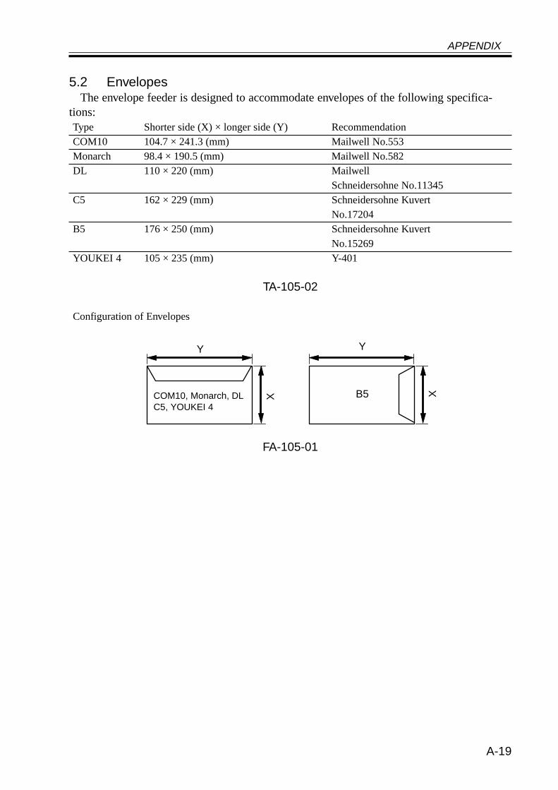
APPENDIX
A-19
5.2 EnvelopesThe envelope feeder is designed to accommodate envelopes of the following specifica-
tions:Type Shorter side (X) × longer side (Y) RecommendationCOM10 104.7 × 241.3 (mm) Mailwell No.553Monarch 98.4 × 190.5 (mm) Mailwell No.582DL 110 × 220 (mm) Mailwell
Schneidersohne No.11345C5 162 × 229 (mm) Schneidersohne Kuvert
No.17204B5 176 × 250 (mm) Schneidersohne Kuvert
No.15269YOUKEI 4 105 × 235 (mm) Y-401
TA-105-02
Configuration of Envelopes
FA-105-01
COM10, Monarch, DLC5, YOUKEI 4
Y
X
Y
B5 X
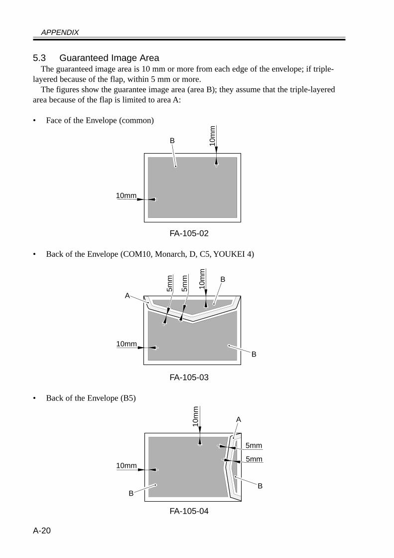
APPENDIX
A-20
5.3 Guaranteed Image AreaThe guaranteed image area is 10 mm or more from each edge of the envelope; if triple-
layered because of the flap, within 5 mm or more.The figures show the guarantee image area (area B); they assume that the triple-layered
area because of the flap is limited to area A:
• Face of the Envelope (common)
FA-105-02
• Back of the Envelope (COM10, Monarch, D, C5, YOUKEI 4)
FA-105-03
• Back of the Envelope (B5)
FA-105-04
10mm
10m
m
B
10mm
10m
m
B
B
A
5mm
5mm
10mm
10m
m
BB
A
5mm
5mm
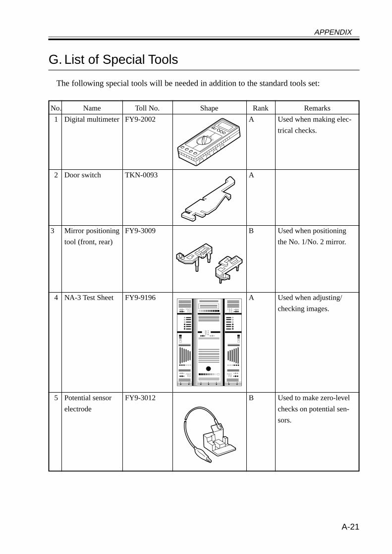
APPENDIX
A-21
G. List of Special Tools
The following special tools will be needed in addition to the standard tools set:
No.
1
2
3
4
5
Name
Digital multimeter
Door switch
Mirror positioning
tool (front, rear)
NA-3 Test Sheet
Potential sensor
electrode
Toll No.
FY9-2002
TKN-0093
FY9-3009
FY9-9196
FY9-3012
Shape Rank
A
A
B
A
B
Remarks
Used when making elec-
trical checks.
Used when positioning
the No. 1/No. 2 mirror.
Used when adjusting/
checking images.
Used to make zero-level
checks on potential sen-
sors.
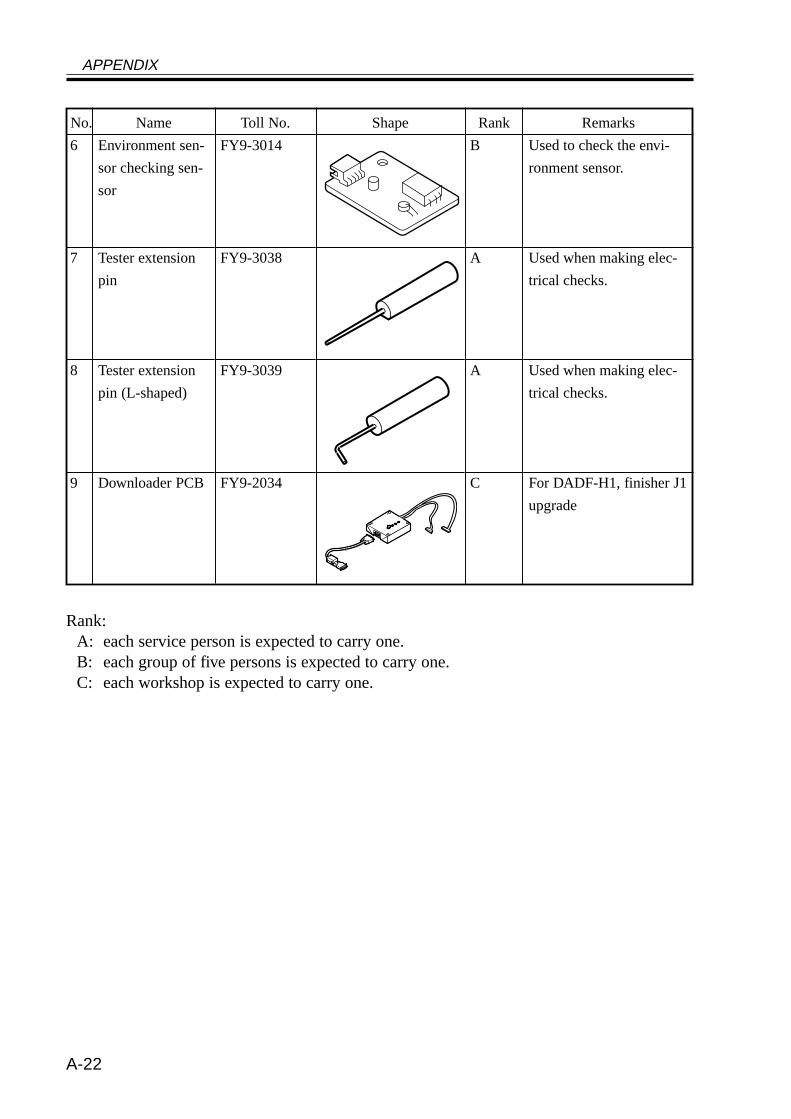
APPENDIX
A-22
No.
6
7
8
9
Name
Environment sen-
sor checking sen-
sor
Tester extension
pin
Tester extension
pin (L-shaped)
Downloader PCB
Toll No.
FY9-3014
FY9-3038
FY9-3039
FY9-2034
Rank
B
A
A
C
Remarks
Used to check the envi-
ronment sensor.
Used when making elec-
trical checks.
Used when making elec-
trical checks.
For DADF-H1, finisher J1
upgrade
Rank:A: each service person is expected to carry one.B: each group of five persons is expected to carry one.C: each workshop is expected to carry one.
Shape
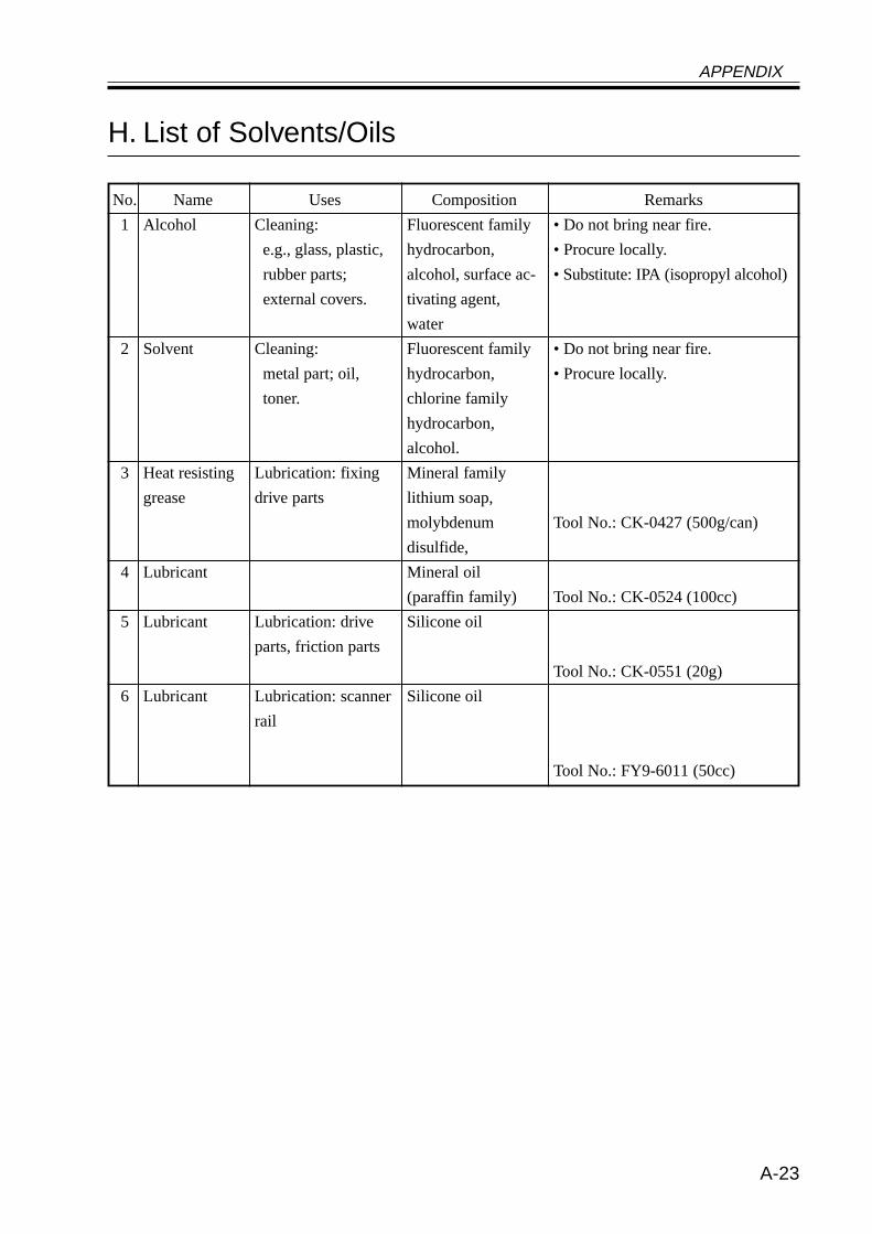
APPENDIX
A-23
No.
1
2
3
4
5
6
H. List of Solvents/Oils
Name
Alcohol
Solvent
Heat resisting
grease
Lubricant
Lubricant
Lubricant
Uses
Cleaning:
e.g., glass, plastic,
rubber parts;
external covers.
Cleaning:
metal part; oil,
toner.
Lubrication: fixing
drive parts
Lubrication: drive
parts, friction parts
Lubrication: scanner
rail
Composition
Fluorescent family
hydrocarbon,
alcohol, surface ac-
tivating agent,
water
Fluorescent family
hydrocarbon,
chlorine family
hydrocarbon,
alcohol.
Mineral family
lithium soap,
molybdenum
disulfide,
Mineral oil
(paraffin family)
Silicone oil
Silicone oil
Remarks
• Do not bring near fire.
• Procure locally.
• Substitute: IPA (isopropyl alcohol)
• Do not bring near fire.
• Procure locally.
Tool No.: CK-0427 (500g/can)
Tool No.: CK-0524 (100cc)
Tool No.: CK-0551 (20g)
Tool No.: FY9-6011 (50cc)


Prepared by
Office Imaging Products Quality Assurance Center
CANON INC.
Printed in Japan
REVISION 0 (MAY 2001) (18723/18756/22109/32205/35338)
5-1, Hakusan 7-chome, Toride-shi, Ibaraki 302-8501 Japan

PRINTED IN JAPAN (IMPRIME AU JAPON) 0501M0.80-1
This publication is printed on 100% recycled paper.


![COMPRESSION TUBE FITTINGS - reeglles.com fitting_installation guide.pdf · compression tube fittings ... jvuzpz[lu[ kyp] ... 2400 3100 3600 4200 4700 1 1/4 2400 2800 3300 3600 4100](https://img.pdfslide.net/doc/110x75/5aded8797f8b9af05b8ba488/compression-tube-fittings-fittinginstallation-guidepdfcompression-tube-fittings.jpg)


![SOLERIQ S 13 Datasheet Version 1.2 GW KAGMB3 · 2018-05-08 Datasheet Version 1.2 ... [lm] (typ.) IV [cd] TP 2800 3040 929.3 TQ 3040 3300 1008.9 TR 3300 3590 1096.4 TS 3590 3900 1191.9](https://img.pdfslide.net/doc/110x75/5c8fce9209d3f282338b4d56/soleriq-s-13-datasheet-version-12-gw-kagmb3-2018-05-08-datasheet-version-12.jpg)


![Canon iR2200, iR2800, iR3300 Service Handbook[1]](https://img.pdfslide.net/doc/110x75/54f6b4184a7959430c8b4802/canon-ir2200-ir2800-ir3300-service-handbook1.jpg)