Embed Size (px)
Citation preview
Canon MP730 Printer Purge Unit Disassembly and Assembly By G. Patton
Copyright © 2008 by G. Patton All Rights Reserved
When I disassembled and reassembled my Canon MP730 printer recently I found my purge unit QG40279000 had its gears covered in ink since I had not cleaned up the ink when I got the Waste Ink Tank Full warning. At the time I just ordered a new unit, installed it, and the printer works fine. However, for fun I then partially took apart the old purge unit to see if it could be easily cleaned. I have not put it back in the printer to determine that it works so I really can’t say my procedure works but it seems ok.
Warnings and Safety There is no electrical hazard since the unit is unplugged and since it took so long to get to the unit it should not be hot. The big danger then is getting the ink onto things. Have a role of paper towels ready and work over newspapers. You follow these directions at your own risk and I am not libel for damage to your printer or to you or your house (ink damage etc. or any other problems). Also your purge unit may be different from the one that I took apart and so your experience may be different for which I am not to blame. You proceed at your own risk.
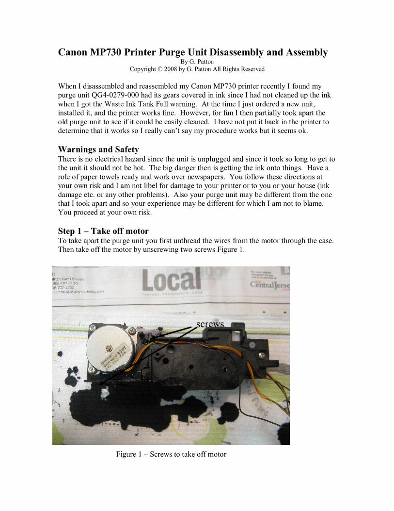
Step 1 – Take off motor To take apart the purge unit you first unthread the wires from the motor through the case. Then take off the motor by unscrewing two screws Figure 1.
Figure 1 – Screws to take off motor
screws

Copyright © 2008 G. Patton, All Rights Reserved 2
Set the screws and the motor aside in a cup for later assembly. At this point you could probably wash the purge unit in water and get most of the ink out and not take it apart further. We really just didn’t want to get the motor wet. However, it is easy to go a little further.
Step 2 – Take off right side Take off the right side of the purge (as you look at it from the motor end). There are again 2 screws. It should come off fairly easily with all the gears in it intact. Also no pieces should fall off from the inside. The flipped off right side should look like Figure 2 but without all the ink.
Figure 2 – Right side of purge unit flipped over
Note the big gear on the left has small teeth and is fastened to the case, the others have larger teeth on the outer rim. The gear on the right has a black rim and a stub protruding up from it. This engages in the black gear on a unit in the other half as we will see later.
Step 3 – Take off the plate that slides the wiper The purge unit with the right side off is shown in Figure 3. The top in the picture is really the right side.
stub

Copyright © 2008 G. Patton, All Rights Reserved 3
Figure 3 – Right side of purge unit
The large white plate in the center slides left and right moving the wiper blades to clean the print head. The black solid looking gear on the right is the key to all the movements. It has a hole in it where the stub poking up from the gear in Figure 2 goes when the right side is closed. The gear also has a catch that hooks onto the white plate. Turning the black gear, very carefully and it is pretty hard to turn, causes the purge unit vacuum head to move up and down. It also causes the print head carrier lock (which is in the piece with the gears), to be locked and covered or unlocked and uncovered for printing. I took the white plate off by unhooking it from the black gear and sliding it to the left where there is a notch in the frame where a bottom hook can be pulled through. Then with it just pulled through it can slide away from you to unhook two other hooks that hold it to the frame. You should see a white gear that sits under the plate Figure 4.
Figure 4 – Position of white gear
hole
white plate
white gear

Copyright © 2008 G. Patton, All Rights Reserved 4
You can take out the white gear and put it in a cup with the white plate. At this point I felt I could pretty much see everything so I stopped taking things apart and washed everything in water. Of course you don’t want to wash anything down the drain, like a spring or a gear but surprisingly everything pretty much stayed together. The one part I was a little careful of was the sensor unit with the wires coming from it. Since the Canon ink is conductive you don’t want to leave any ink between any connections that could short the printer. Thus don’t get ink on the connections while washing and if you do rinse it off thoroughly.
I should mention that the actions of the purge unit are preformed by having a motor that rotates two ways. One way it raises and lowers the suction heads and the locking arm. The other way it creates the suction. It knows when the suction heads are raised or lowered by getting input from a sensor which is activated by one of the sections of the black gear going between two arms of the sensor that has the other wires coming from it.
I could have taken off the left side at this point but I felt I could clean it well enough without doing that. Most of the gears with the ink were on the right side which was washed thoroughly.
Reassembly
1. Put on the white plate – First put in the white gear and position it so the white plate stub goes into the hole in the gear. Position the plate so the hooks on the top of the plate are over the frame it slides on and then put the lower hook through the hole in the frame and slide the unit right. I slid it over until it hooked on the black gear as it was in the beginning. There is probably an official procedure for this but I don’t know it.
Figure 5 – A cleaned up white plate and black gear
black gear
sensor unit
gear hook
grease

Copyright © 2008 G. Patton, All Rights Reserved 5
Probably if I were a repair person I would put some proper grease on the sliding parts of the unit and the gears here. Canon suggests you use a special grease. I didn’t use any but you will note there was some of the original grease left even after cleaning. When putting the white plate on I turned the black gear so the hook was in the upper left quadrant and the white plate just hooked into it as when I took it apart as in figure 3.
2. Put on the right side. This is tricky. First I rotated the gears in the right side so the stub on the gear on the right would fit into the hole in the black gear. Then I flipped the right side over and put it on making sure the black gear’s end point went in the hole in the case and that the stub on the white gear went in the black gears hole. At the same time I slightly turned the gear on the left so it meshed with the gear on the mechanism which turns and creates the suction. Also I held the locking pin down and made sure its spring was seated. Thus there are four things that have to be done at once. If everything meshes the right side will fit flat on the case and you can put in the two screws. If you have done it correctly 1) the locking pin will not be so tight it won’t move up and down easily, 2) turning the large gear whose teeth show just inside the right cover clockwise will cause the suction assembly to go up and down and the wiper to go back and forth. Note it takes a little pressure on the gear to make these things happen but don’t break the gear teeth. This is probably the trickiest part of the whole job. Note that the suction assembly won’t go down if the purge unit is sitting on a table since the suction tubes come below the case when the unit is down. Figure 6
Figure 6 – Suction tubes hanging down
If the suction unit is not all the way down the wiper will hit it and damage the wiper. So when testing, hold the unit in your hand with nothing under the bottom as you turn the gear.

Copyright © 2008 G. Patton, All Rights Reserved 6
Also at this point check that the rubber tubes coming from the plastic nipples of the suction area are connected and that they didn’t come detached in the cleaning. If they did come detached there will be no suction in the suction area and no ink coming to the print head via suction. The bottom of the purge unit should look like Figure 7.
Figure 7a – Bottom of purge unit with tubes Figure 7b bottom of purge unit gears
There should be two tube ends and two tubes curving down with the left end connected to the bottom of the suction area.
3. Put on the motor. If everything is working smoothly when you turn the big gear then you can put the motor back on making sure the gears mesh. Two screws.
Figure 8– Suction holes exposed wiper on left Figure 9 – Suction holes exposed Suction units are up suction units are down
Figures 8 and 9 are looking from the left (other side) of the purge unit and show the suction and wiper units after cleaning. Usually there are ceramic pads over the holes. When the suction units are up it protects the print head holes and keeps the print head from drying out. When it is down the wiper can wipe over the head taking off extra ink and then the print head can move across the paper and print the page.
Tube connection
Ink comes out here

Copyright © 2008 G. Patton, All Rights Reserved 7
Figure 10 – During the wiping process
Figure 10 shows the wipers in action moving from left to right over the suction unit which has dropped down. Note there is a wiper to wipe the wiping unit on the right and the wiping unit should move far enough to get wiped by the unit on the right. Figure 10 is also looking from the left side of the purge unit.
Well reassembly is complete after you run the wires back through the case and run the sensor unit wires through the ring that the motor wires are wound around.
As I said I did not try to use the unit after I reassembled it and it may not work for some reason but it looks like it should be ok with all mechanisms moving.
Good luck on your project.