Embed Size (px)
Citation preview
Advances in Aircraft and Spacecraft Science, Vol. 3, No. 1 (2016) 1-14
DOI: http://dx.doi.org/10.12989/aas.2016.3.1.001 1
Copyright © 2016 Techno-Press, Ltd.
http://www.techno-press.org/?journal=aas&subpage=7 ISSN: 2287-528X (Print), 2287-5271 (Online)
Capabilities of 1D CUF-based models to analyse metallic/composite rotors
Matteo Filippi and Erasmo Carrera
Department of Mechanical and Aerospace Engineering, Politecnico di Torino, Italy
(Received July 16, 2015, Revised July 27, 2015, Accepted July 30, 2015)
Abstract. The Carrera Unified Formulation (CUF) is here extended to perform free-vibrational analyses of rotating structures. CUF is a hierarchical formulation, which enables one to obtain refined structural theories by writing the unknown displacement variables using generic functions of the cross-section coordinates (x, z). In this work, Taylor-like expansions are used. The increase of the theory order leads to three-dimensional solutions while, the classical beam models can be obtained as particular cases of the linear theory. The Finite Element technique is used to solve the weak form of the three-dimensional differential equations of motion in terms of „fundamental nuclei‟, whose forms do not depend on the adopted approximation. Including both gyroscopic and stiffening contributions, structures rotating about either transversal or longitudinal axis can be considered. In particular, the dynamic characteristics of thin-walled cylinders and composite blades are investigated to predict the frequency variations with the rotational speed. The results reveal that the present one-dimensional approach combines a significant accuracy with a very low computational cost compared with 2D and 3D solutions. The advantages are especially evident when deformable and composite structures are analyzed.
Keywords: composites; carrera unified formulation; finite element method; rotordynamics
1. Introduction
Many engineering applications require the use of rotating structures, whose design can
represent a crucial task of the whole project. The modelling of the rotating structures is typically
made with beam formulations. Many researchers adopted Euler-Bernoulli theory to investigate the
vibrational behavior of spinning shafts (Bauer 1980, Chen and Liao 1991, Banerjee and Su 2004)
and centrifugally stiffened beams (Banerjee 2000, Banerjee et al. 2006, Ozge and Kaya 2006, Mei
2008) by adopting analytical and numerical approaches to solve the equations of motion (EoM).
Unfortunately, these solutions are inadequate for stubby bodies, in which rotary inertia and shear
effects play an important role. To include these effects, many theories have been developed on the
basis of Timoshenko beam model (Hodges and Rutkowski 1981, Curti et al. 1991, Curti et al.
1992, Rao and Gupta 2001, Banerjee 2001, Yoo et al. 2005). Although this formulation introduces
relevant improvements, it is no longer suitable when torsion and cross-sectional warping become
significant. In addition, the wide use of composite materials has introduced more difficulties in the
Corresponding author, Professor, E-mail: [email protected]
Matteo Filippi and Erasmo Carrera
modelling of rotating structures giving a further impulse to the development of refined beam
theories. For instance, advanced structural models encompassing transverse shear, secondary
warping and non-uniform torsion were proposed by Song and Librescu (1997b), Chandiramani et
al. (2002, 2003), Jung et al. (1999) in order to study the effects of the lamination scheme and the
pretwisted angle on the rotating natural frequencies of thin-walled blade configurations. On the
basis of these structural theories, critical speeds as well as stability were investigated considering
spinning box beams (Song and Librescu 1997a, Song et al. 2000) and cylinders (Na et al. 2006).
Jung et al. (2001) developed a refined 1D formulation based on a mixed variational approach to
evaluate the effects of elastic coupling, shell-wall thickness, warping restraint and transverse shear
deformation on the dynamics of composite rotor blades. According to this formulation, the wall
was modelled as a shell while the global beam behaviour was determined using the Timoshenko
theory. When the beam assumptions become too restrictive (significant cross-section
deformations, elastic coupling, etc.) more sophisticated solutions are required. For instance, Genta
et al. (1996, 2010) assumed the displacements of a thin disc as a superimposition of a rigid motion
and a deflection about the rigid body configuration. According to this assumption, the last
contribution was approximated with a truncated Fourier series in the tangential direction whereas,
for the radial direction, polynomial functions were used. Jang and Lee (2002) used the substructure
synthesis and the finite element technique for the analysis of a spinning disk-spindle system on a
flexible shaft. The disc was modelled by using Kirchoff elements whereas Rayleigh and Euler-
Bernoulli theories were adopted for the spindle and the stationary shaft, respectively. Furthermore,
Combescure and Lazarus (2008) proposed a thorough comparison between 1D, 2D Fourier and
3D solutions for the study of the dynamics of large rotating structures. Over the years, several shell
theories have been proposed to analyse the dynamics of thin (Guo et al. 2002, Saito and Endo
1985, Chen et al. 1993, Lam and Loy 1995, Ramezani and Ahmadian 2009) and thick (Guo et al.
2001) rotating cylindrical shells.
This paper presents an overview of the capabilities of the refined 1D models obtained through
the Carrera Unified Formulation (CUF) for the study of various rotating structures. Despite being
based on a 1D formulation, the present methodology provides 2D and quasi-3D results. Carrera
(2002, 2003) first proposed his unified formulation for plates and shells and later for the beam
approach (Carrera et al. 2011, Carrera et al. 2014a). Within the scope of this work, Carrera et al.
(2013a, 2013b) and Carrera and Filippi (2014b, 2015) recently adopted the 1D-CUF elements to
evaluate the dynamic behavior of compact isotropic and laminated shafts, rectangular composite
blades and thin-walled spinning cylinders. In the following sections, further assessments are
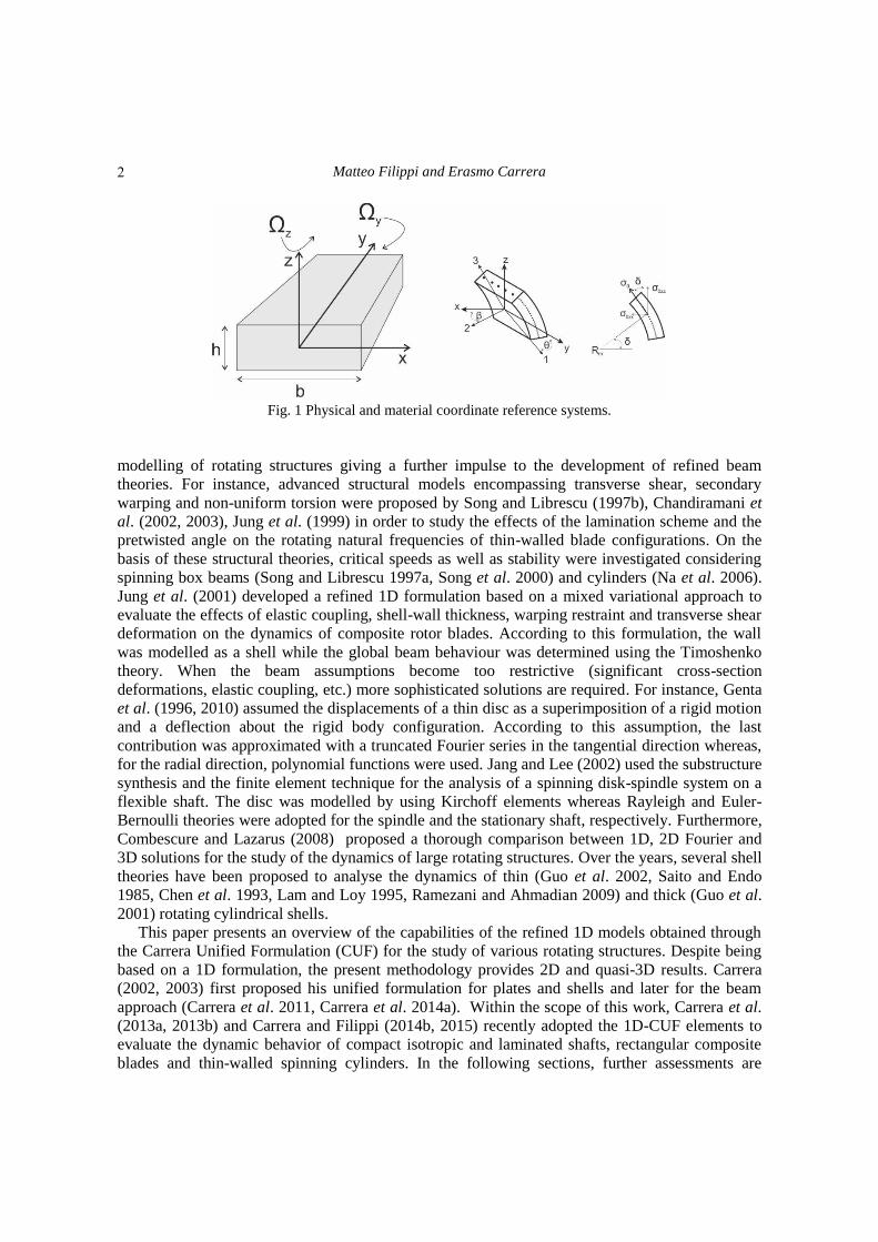
Fig. 1 Physical and material coordinate reference systems.
2
Capabilities of 1D CUF-based models to analyze metallic/composite rotors
proposed considering new rotating structures, including a membrane and laminated box beams. All
results are compared with either theoretical or numerical solutions.
2. The Kinetic and potential energies
Let us consider a structure that is free to rotate about its either longitudinal or transverse axis,
as shown in Fig. 1. The absolute velocity of the point P is the sum of the relative velocity and the
transfer velocity
𝒗𝑎𝑏𝑠 = 𝒗𝑟𝑒𝑙 + 𝒗𝑡 = �� + 𝜴 × 𝒓𝒕𝒐𝒕 (1)
𝜴 = [
] (2)
where u = {ux,uy,uz}T is the displacement vector and rtot = r + u is the distance of P from the
neutral axis. The kinetic energy of the whole structure is expressed by the following formula
𝑇 = 1
2 ∫ 𝜌(��𝑇�� + 2 𝒖𝑇𝜴𝑇�� + 𝒖𝑇𝜴𝑇𝜴𝒖 + 2��𝑇𝜴𝒓 + 2𝒖𝑇𝜴𝑇𝜴𝒓 + 𝒓𝑇𝜴𝑇𝜴𝒓)𝑑𝑉
𝑉
(3)
In the linearized analysis, the potential energy of a rotating structure is given by the sum of the
elastic term and a geometric contribution
𝑈 =
1
2 ∫ (𝜺𝑙
𝑇𝑪𝜺) + (𝜎0𝜺𝑛𝑙2 )𝑑𝑉
𝑉
(4)
where C is the matrix of material coefficients (Carrera and Filippi 2014b) and 𝜺𝑙 and 𝜺𝑛 are the
linear and nonlinear components of the strain field. The term 𝜎0 represents the pre-stress
contribution due to the rotational speed. For example, the expressions of 𝜎0 for a centrifugally
stiffened blade ( = ) and for a spinning cylinder ( = ) are, respectively
𝜎0 = 𝑧
2𝜌 [𝑟ℎ𝐿 + 1
2𝐿2 𝑟ℎ
1
2 2] (5)
𝜎0 = 𝑅𝑚2 𝑦
2𝜌 (6)
where L, 𝑟ℎ and 𝑅𝑚 are the length of the beam, the dimension of the hub and the mean radius of
the cylinder, respectively.
3. The Carrera unified formulation
The CUF states that the displacement field, 𝑢( 𝑡), is an expansion of generic functions,
( ), for the vector displacement, 𝑢 ( 𝑡)
𝒖( 𝑡) = ( )𝒖 ( 𝑡) = 1 2 𝑇 (7)
where T stands for the number of the terms used in the expansion, and the repeated subscript,
3
Matteo Filippi and Erasmo Carrera
indicates summation. In this work, Eq. (7) consists of Taylor-like expansions, which are functions
of the coordinates of the cross-section. For example, the second-order displacement field TE2 is
𝑢 = 𝑢 + 𝑢
+ 𝑢 + 2 𝑢
+ 𝑢 + 2 𝑢
𝑢 = 𝑢 + 𝑢
+ 𝑢 + 2 𝑢
+ 𝑢 + 2 𝑢
𝑢 = 𝑢 + 𝑢
+ 𝑢 + 2 𝑢
+ 𝑢 + 2 𝑢
The classical beam theories are obtainable as particular cases of the linear expansion, TE1. It
should be noted that classical theories require reduced material stiffness coefficients to contrast
Poisson‟s locking. Unless otherwise specified, for classical and first-order models Poisson‟s
locking is corrected according to (Carrera et al. 2014a). According to the Finite Element
technique, the generalized displacement vector becomes
𝒖 ( 𝑡) = ( ) (𝑡) (8)
where ( ) are the shape functions and (𝑡) is the nodal displacement vector (𝑡) =
{
}T
.
4. Governing equations of rotating and spinning structures
The EoM are obtained through the Hamilton‟s Principle
∫ (𝑇 𝑈)𝑑𝑡 =
0
(9)
in which is the virtual variation of the functional. The homogeneous EoM are
+ + ( + + ) = (10)
where the matrices are written in terms of „fundamental nuclei‟. Besides the mass and stiffness
matrices, and , the other three contributions are: the Coriolis matrix , the softening
matrix
and the centrifugal stiffening matrix
due to the rotation.
= 𝑙
( 𝜌 )
= 2 𝑙
( 𝜌 )
= 𝑇 𝑙
( 𝜌 )
= 𝑙
𝑛 𝑇 ( )[𝑪𝑛 ( ) + 𝑪𝑛𝑛 𝑛 ( )] +
+ 𝑇 ( )[𝑪 ( ) + 𝑪 𝑛 𝑛 ( )]
+ 𝑙 𝑦
𝑛 𝑇 ( ) +
𝑇( ) 𝑪 𝑛 𝑦
+ 𝑙 𝑦
𝑦𝑇 𝑪𝑛
𝑇( ) + 𝑪𝑛𝑛 𝑛 𝑇 ( )
+ 𝑙 𝑦 𝑦
𝑦𝑇 𝑦 𝑪𝑛𝑛
(11a)
4
Capabilities of 1D CUF-based models to analyze metallic/composite rotors
The expressions of the centrifugal stiffening fundamental nuclei for a spinning and rotating
structure are, respectively
= 𝑙
( 𝜎0
) + ( 𝑧𝜎0
𝑧 ) + ( 𝜎0
𝑧 ) + ( 𝑧𝜎0
)
= 𝑙
𝑦 𝑦 𝑇 ( 𝜌 ) (11a)
where
𝑦 = [ 1
1 1
] = [1
1 1
]
= ∫ 𝑑
𝑙 𝑙
𝑦 𝑙
𝑦 𝑙
𝑦 𝑦 𝑙
𝑦 𝑦= ∫ ( 𝑦
𝑙
𝑦 𝑦 𝑦 𝜎0 𝑦 𝑦) 𝑑
The terms 𝜎0 𝜎0
𝜎0 are the components of the pre-stress distribution of Eq. (6) written in
the Cartesian coordinate system.
5. Numerical results
5.1 Spinning structures
5.1.1 Thin-walled cylinder A clamped-clamped cylinder with the wall thickness, t=0.05 m, mean diameter, d=1.0 m, and
length, L=3 m, is considered. The Young‟s modulus, Poisson‟s ratio and density are E=207 Gpa,
=0.3 and 𝜌=7860 kg/m3, respectively. The mathematical model consists of seven 4-node beam
elements along the longitudinal direction. With purposes of comparison, the natural frequencies in
the non-rotating state are compared in Table 1 with those obtained with a 2D Nastran finite
element solution. The first two columns report the wave numbers along the circumferential and
longitudinal directions, respectively. The comparisons reveal that the TE8 theory predicts
Table 1 Natural frequencies [Hz] of the non-rotating cylinder
n m TE7 TE8 2D Nastran
2 1 223.77 223.62 222.08
1 1 336.88 336.88 335.26
3 1 472.64 400.72 394.78
2 2 417.48 417.06 414.59
3 2 547.10 484.49 473.00
Torsional 530.44 530.44 527.69
3 3 679.18 627.69 609.04
2 3 652.89 652.11 647.17
1 2 664.21 664.21 661.02
5
Matteo Filippi and Erasmo Carrera
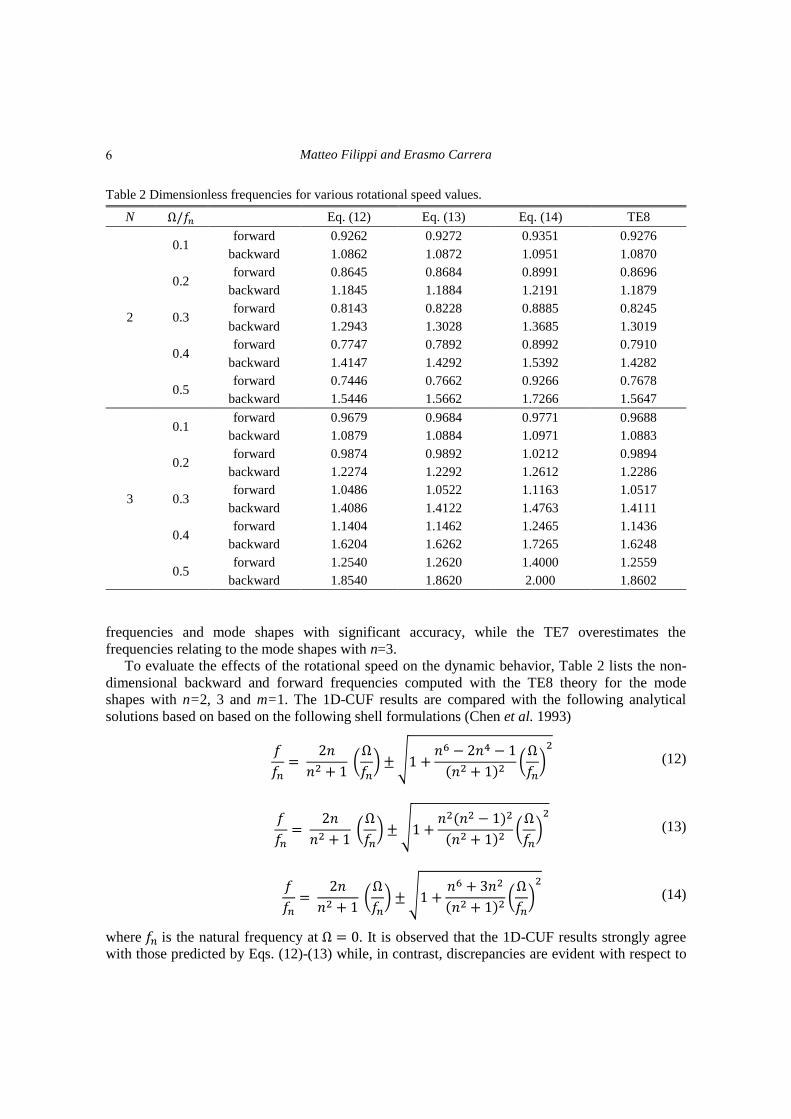
Table 2 Dimensionless frequencies for various rotational speed values.
N 𝑓𝑛 Eq. (12) Eq. (13) Eq. (14) TE8
2
0.1 forward 0.9262 0.9272 0.9351 0.9276
backward 1.0862 1.0872 1.0951 1.0870
0.2 forward 0.8645 0.8684 0.8991 0.8696
backward 1.1845 1.1884 1.2191 1.1879
0.3 forward 0.8143 0.8228 0.8885 0.8245
backward 1.2943 1.3028 1.3685 1.3019
0.4 forward 0.7747 0.7892 0.8992 0.7910
backward 1.4147 1.4292 1.5392 1.4282
0.5 forward 0.7446 0.7662 0.9266 0.7678
backward 1.5446 1.5662 1.7266 1.5647
3
0.1 forward 0.9679 0.9684 0.9771 0.9688
backward 1.0879 1.0884 1.0971 1.0883
0.2 forward 0.9874 0.9892 1.0212 0.9894
backward 1.2274 1.2292 1.2612 1.2286
0.3 forward 1.0486 1.0522 1.1163 1.0517
backward 1.4086 1.4122 1.4763 1.4111
0.4 forward 1.1404 1.1462 1.2465 1.1436
backward 1.6204 1.6262 1.7265 1.6248
0.5 forward 1.2540 1.2620 1.4000 1.2559
backward 1.8540 1.8620 2.000 1.8602
frequencies and mode shapes with significant accuracy, while the TE7 overestimates the
frequencies relating to the mode shapes with n=3.
To evaluate the effects of the rotational speed on the dynamic behavior, Table 2 lists the non-
dimensional backward and forward frequencies computed with the TE8 theory for the mode
shapes with n=2, 3 and m=1. The 1D-CUF results are compared with the following analytical
solutions based on based on the following shell formulations (Chen et al. 1993)
𝑓
𝑓𝑛=
2
2 + 1 (
𝑓𝑛) √1 +
2 1
( 2 + 1)2(
𝑓𝑛)2
(12)
𝑓
𝑓𝑛=
2
2 + 1 (
𝑓𝑛) √1 +
2( 2 1)2
( 2 + 1)2(
𝑓𝑛)2
(13)
𝑓
𝑓𝑛=
2
2 + 1 (
𝑓𝑛) √1 +
+ 3 2
( 2 + 1)2(
𝑓𝑛)2
(14)
where 𝑓𝑛 is the natural frequency at = . It is observed that the 1D-CUF results strongly agree
with those predicted by Eqs. (12)-(13) while, in contrast, discrepancies are evident with respect to
6
Capabilities of 1D CUF-based models to analyze metallic/composite rotors
the solution of Eq. (14). As pointed out in (Chen et al. 1993), the differences arise from the
differing treatments of high order infinitesimal various shell theories.
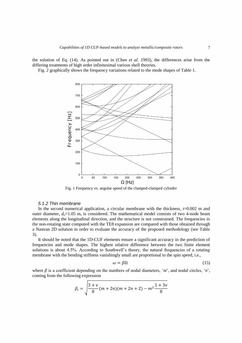
Fig. 2 graphically shows the frequency variations related to the mode shapes of Table 1.
Fig. 1 Frequency vs. angular speed of the clamped-clamped cylinder
5.1.2 Thin membrane In the second numerical application, a circular membrane with the thickness, t=0.002 m and
outer diameter, do=1.05 m, is considered. The mathematical model consists of two 4-node beam
elements along the longitudinal direction, and the structure is not constrained. The frequencies in
the non-rotating state computed with the TE8 expansion are compared with those obtained through
a Nastran 2D solution in order to evaluate the accuracy of the proposed methodology (see Table
3).
It should be noted that the 1D-CUF elements ensure a significant accuracy in the prediction of
frequencies and mode shapes. The highest relative difference between the two finite element
solutions is about 4.5%. According to Southwell‟s theory, the natural frequencies of a rotating
membrane with the bending stiffness vanishingly small are proportional to the spin speed, i.e.,
= (15)
where is a coefficient depending on the numbers of nodal diameters, „m‟, and nodal circles, „n‟,
coming from the following expression
= √3 +
( + 2 )( + 2 + 2) 2
1 + 3
7
Matteo Filippi and Erasmo Carrera
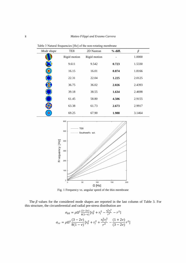
Table 3 Natural frequencies [Hz] of the non-rotating membrane
Mode shape TE8 2D Nastran % diff.
Rigid motion Rigid motion - 1.0000
9.611 9.542 0.723 1.5330
16.15 16.01 0.874 1.8166
22.31 22.04 1.225 2.0125
36.75 36.02 2.026 2.4393
39.18 38.55 1.634 2.4698
61.45 58.80 4.506 2.9155
63.38 61.73 2.673 2.9917
69.25 67.90 1.988 3.1464
Fig. 1 Frequency vs. angular speed of the thin membrane
The values for the considered mode shapes are reported in the last column of Table 3. For
this structure, the circumferential and radial pre-stress distribution are
𝜎 = 𝜌 2 ( 2 )
( ) 𝑟0
2 + 𝑟 2
𝑟2]
𝜎 = 𝜌 2(3 2 )
(1 ) 𝑟0
2 + 𝑟 2 +
𝑟02𝑟
2
𝑟2 (1 + 2 )
(3 2 )𝑟2
8
Capabilities of 1D CUF-based models to analyze metallic/composite rotors
where „ri‟, „r0‟ are the inner and outer radii. The frequency curves are shown in Fig. 2. It should
be noted that the frequency branches predicted with the present formulation asymptotically follow
the curves of Eq. (15) for relatively high speeds when the centrifugal stiffness supplies the in-plane
stretching.
5.2 Rotating blades
5.2.1 Laminated beams The structures are two graphite-epoxy rectangular beams whose width is c=25.4 mm. The
thickness and fiber orientations are different for the two cases, and they are listed in Table 4 with
the relating material properties. The beam length, L, is a problem parameter and, two different
aspect ratios are studied (L/c=10, 20). The cantilevered blade configurations are modelled using
eight 4-node beam elements. The reference solutions are taken from (Yeo et al. 2010), where the
authors presented comparisons between 1D and 3D formulations for various blade configurations.
In particular, the 1D beam analyses were performed using the Variational Asymptotic Beam
Sectional (VABS) approach in order to compute the 2D cross-sectional properties of the blade,
whereas the 3D solutions were obtained with the commercial code MSC/Marc.
Table 4 Material properties and thicknesses of the graphite-epoxy laminated beams
Case Thickness [mm] Fiber Orientation [deg]
1 2.97 0°
2 3.22 15°
Property
E11 142.0 [GPa]
E22=E33 9.80 [GPa]
G21=G31 6.00 [GPa]
G32 6.00 [GPa]
ν12=ν13 0.42
ν23 0.54
ρ 1538 [kg/m3]
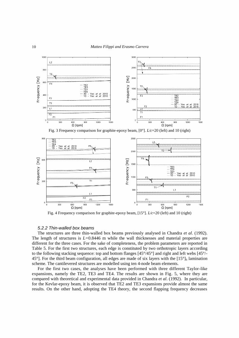
Fig. 3 shows the frequency variations for the [0°] lamination sequence obtained with various
TE models. For L/c=20, it is observed that all theories provide almost the same results except for
slight difference in the computation of the second torsional frequency curve. When the L/c ratio
decreases, the 1D-VABS solution underestimates the second and third torsional frequencies with
respect to TE and 3D models. Moreover, it should be noted that the increasing of the TE order
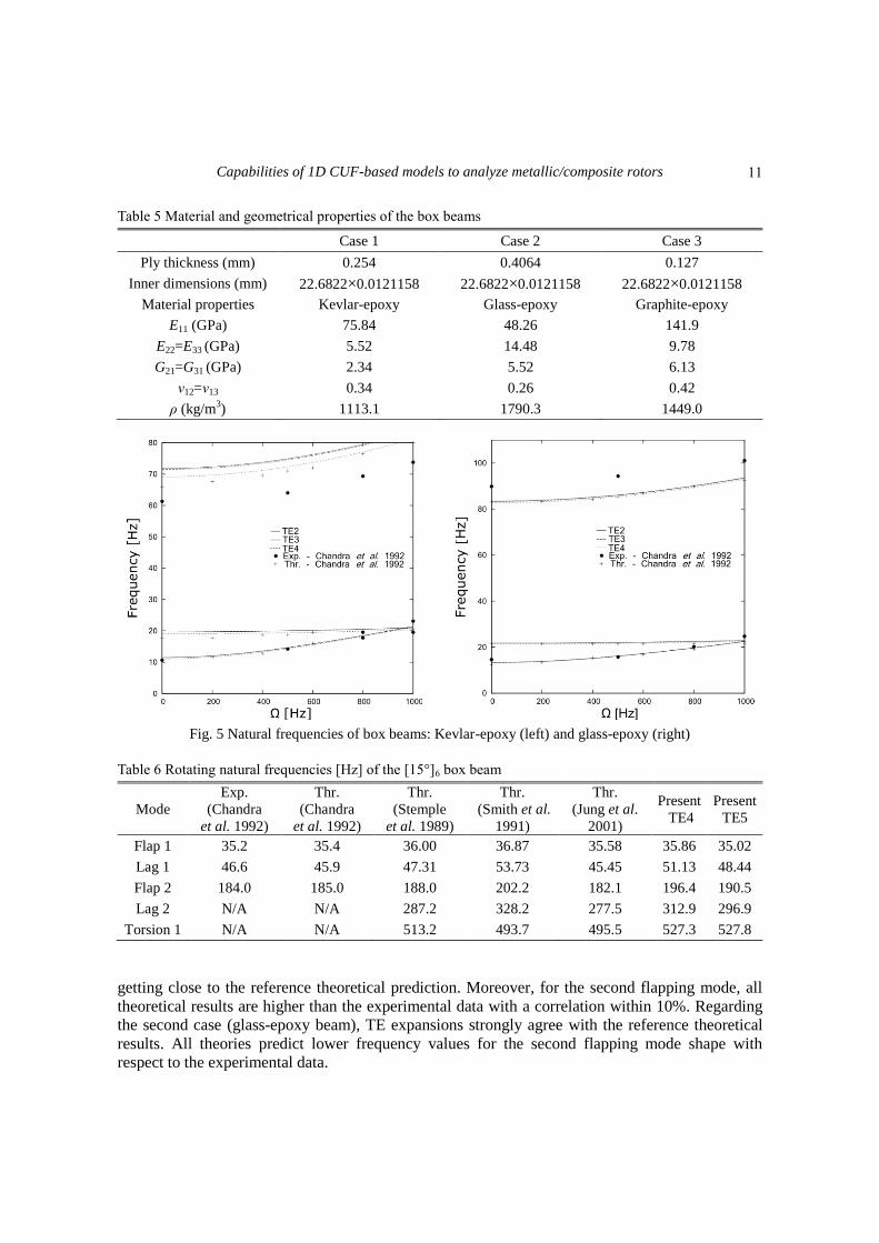
ensures the convergence of the proposed results to the solid solution. Regarding the [15°]
lamination sequence, the results are shown in Fig. 4. Due to the bending-torsion coupling, the
discrepancies between the 1D-VABS and the other theories (TE and 3D) are also evident for the
third, fourth and fifth flapping modes. Despite the significant coupling effects, the TE elements
provide results very close to solid solutions for both considered L/c ratios.
9
Matteo Filippi and Erasmo Carrera
Fig. 3 Frequency comparison for graphite-epoxy beam, [0°]. L/c=20 (left) and 10 (right)
Fig. 4 Frequency comparison for graphite-epoxy beam, [15°]. L/c=20 (left) and 10 (right)
5.2.2 Thin-walled box beams The structures are three thin-walled box beams previously analysed in Chandra et al. (1992).
The length of structures is L=0.8446 m while the wall thicknesses and material properties are
different for the three cases. For the sake of completeness, the problem parameters are reported in
Table 5. For the first two structures, each edge is constituted by two orthotropic layers according
to the following stacking sequence: top and bottom flanges [45°/45°] and right and left webs [45°/-
45°]. For the third beam configuration, all edges are made of six layers with the [15°]6 lamination
scheme. The cantilevered structures are modelled using ten 4-node beam elements.
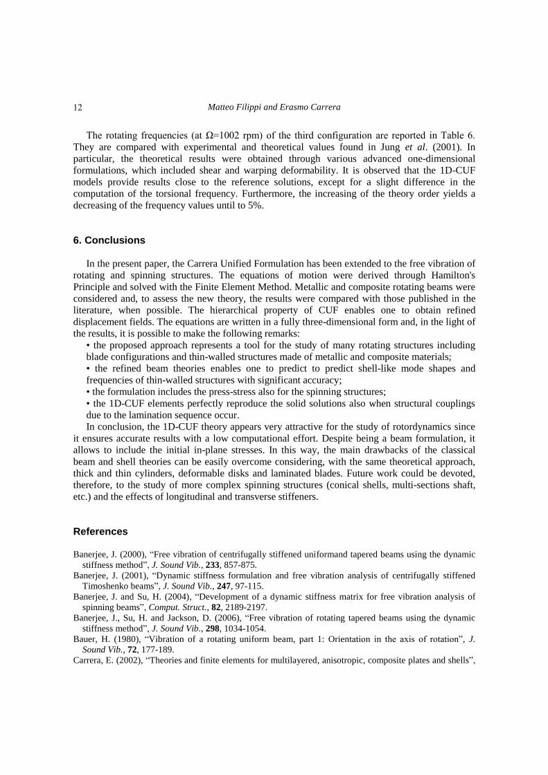
For the first two cases, the analyses have been performed with three different Taylor-like
expansions, namely the TE2, TE3 and TE4. The results are shown in Fig. 5, where they are
compared with theoretical and experimental data provided in Chandra et al. (1992). In particular,
for the Kevlar-epoxy beam, it is observed that TE2 and TE3 expansions provide almost the same
results. On the other hand, adopting the TE4 theory, the second flapping frequency decreases
10
Capabilities of 1D CUF-based models to analyze metallic/composite rotors
Table 5 Material and geometrical properties of the box beams
Case 1 Case 2 Case 3
Ply thickness (mm) 0.254 0.4064 0.127
Inner dimensions (mm) 22.6822×0.0121158 22.6822×0.0121158 22.6822×0.0121158
Material properties Kevlar-epoxy Glass-epoxy Graphite-epoxy
E11 (GPa) 75.84 48.26 141.9
E22=E33 (GPa) 5.52 14.48 9.78
G21=G31 (GPa) 2.34 5.52 6.13
ν12=ν13 0.34 0.26 0.42
ρ (kg/m3) 1113.1 1790.3 1449.0
Fig. 5 Natural frequencies of box beams: Kevlar-epoxy (left) and glass-epoxy (right)
Table 6 Rotating natural frequencies [Hz] of the [15°]6 box beam
Mode
Exp.
(Chandra
et al. 1992)
Thr.
(Chandra
et al. 1992)
Thr.
(Stemple
et al. 1989)
Thr.
(Smith et al.
1991)
Thr.
(Jung et al.
2001)
Present
TE4
Present
TE5
Flap 1 35.2 35.4 36.00 36.87 35.58 35.86 35.02
Lag 1 46.6 45.9 47.31 53.73 45.45 51.13 48.44
Flap 2 184.0 185.0 188.0 202.2 182.1 196.4 190.5
Lag 2 N/A N/A 287.2 328.2 277.5 312.9 296.9
Torsion 1 N/A N/A 513.2 493.7 495.5 527.3 527.8
getting close to the reference theoretical prediction. Moreover, for the second flapping mode, all
theoretical results are higher than the experimental data with a correlation within 10%. Regarding
the second case (glass-epoxy beam), TE expansions strongly agree with the reference theoretical
results. All theories predict lower frequency values for the second flapping mode shape with
respect to the experimental data.
11
Matteo Filippi and Erasmo Carrera
The rotating frequencies (at Ω=1002 rpm) of the third configuration are reported in Table 6.
They are compared with experimental and theoretical values found in Jung et al. (2001). In
particular, the theoretical results were obtained through various advanced one-dimensional
formulations, which included shear and warping deformability. It is observed that the 1D-CUF
models provide results close to the reference solutions, except for a slight difference in the
computation of the torsional frequency. Furthermore, the increasing of the theory order yields a
decreasing of the frequency values until to 5%.
6. Conclusions
In the present paper, the Carrera Unified Formulation has been extended to the free vibration of
rotating and spinning structures. The equations of motion were derived through Hamilton's
Principle and solved with the Finite Element Method. Metallic and composite rotating beams were
considered and, to assess the new theory, the results were compared with those published in the
literature, when possible. The hierarchical property of CUF enables one to obtain refined
displacement fields. The equations are written in a fully three-dimensional form and, in the light of
the results, it is possible to make the following remarks:
• the proposed approach represents a tool for the study of many rotating structures including
blade configurations and thin-walled structures made of metallic and composite materials;
• the refined beam theories enables one to predict to predict shell-like mode shapes and
frequencies of thin-walled structures with significant accuracy;
• the formulation includes the press-stress also for the spinning structures;
• the 1D-CUF elements perfectly reproduce the solid solutions also when structural couplings
due to the lamination sequence occur.
In conclusion, the 1D-CUF theory appears very attractive for the study of rotordynamics since
it ensures accurate results with a low computational effort. Despite being a beam formulation, it
allows to include the initial in-plane stresses. In this way, the main drawbacks of the classical
beam and shell theories can be easily overcome considering, with the same theoretical approach,
thick and thin cylinders, deformable disks and laminated blades. Future work could be devoted,
therefore, to the study of more complex spinning structures (conical shells, multi-sections shaft,
etc.) and the effects of longitudinal and transverse stiffeners. References Banerjee, J. (2000), “Free vibration of centrifugally stiffened uniformand tapered beams using the dynamic
stiffness method”, J. Sound Vib., 233, 857-875.
Banerjee, J. (2001), “Dynamic stiffness formulation and free vibration analysis of centrifugally stiffened
Timoshenko beams”, J. Sound Vib., 247, 97-115.
Banerjee, J. and Su, H. (2004), “Development of a dynamic stiffness matrix for free vibration analysis of
spinning beams”, Comput. Struct., 82, 2189-2197.
Banerjee, J., Su, H. and Jackson, D. (2006), “Free vibration of rotating tapered beams using the dynamic
stiffness method”, J. Sound Vib., 298, 1034-1054.
Bauer, H. (1980), “Vibration of a rotating uniform beam, part 1: Orientation in the axis of rotation”, J.
Sound Vib., 72, 177-189.
Carrera, E. (2002), “Theories and finite elements for multilayered, anisotropic, composite plates and shells”,
12
Capabilities of 1D CUF-based models to analyze metallic/composite rotors
Arch. Comput. Meth. Eng., 9(2), 87-140.
Carrera, E. (2003), “Theories and finite elements for multilayered plates and shells: a unified compact
formulation with numerical assessment and benchmarking”, Arch. Comput. Meth. Eng., 10(3), 215-296.
Carrera, E., Giunta, G. and Petrolo, M. (2011), Beam Structures, Classical and Advanced Theories, Wiley.
Carrera, E., Cinefra, M., Petrolo, M. and Zappino, E. (2014a), Finite Element analysis of structures through
Unified Formulation, Wiley.
Carrera, E., Filippi, M. and Zappino, E. (2013a), “Analysis of rotor dynamic by one-dimensional variable
kinematic theories”, J. Eng. Gas Turb. Power, 135, 092501.
Carrera, E., Filippi, M. and Zappino, E. (2013b), “Free vibration analysis of rotating composite blades via
carrera unified formulation”, Compos. Struct., 106, 317-325.
Carrera, E. and Filippi, M. (2014b), “Variable kinematic one-dimensional finite elements for the analysis of
rotors made of composite materials”, J. Eng. Gas Turb. Power, 136, 092501.
Carrera, E. and Filippi, M. (2015), “Vibration analysis of thin/thick, composites/metallic spinning
cylindrical shells by refined beam models”, J. Vib. Acoust., ASME, 137(3), 031020.
Chandiramani, N., Librescu, L. and Shete, C. (2002), “On the free-vibration of rotating composite beams
using a higher-order shear formulation”, Aerosp. Sci. Tech., 6, 545-561.
Chandiramani, N., Librescu, L. and Shete, C. (2003), “Vibration of higher-order-shearable pretwisted
rotating composite blades”, Int. J. Mech. Sci., 45, 2017-2041.
Chandra, R. and Chopra, I. (1992), “Experimental-theoretical investigation of the vibration characteristics of
rotating composite box beams”, J. Aircraf., 29, 657-664.
Chen, M. and Liao, Y. (1991), “Vibrations of pretwisted spinning beams under axial compressive loads with
elastic constraints”, J. Sound Vib., 147, 497-513.
Chen, Y., Zhao, H., Shen, Z., Grieger, I. and Kroplin, B.H. (1993), “Vibrations of high speed rotating shells
with calculations for cylindrical shells”, J. Sound Vib., 160, 137-160.
Combescure, D. and Lazarus, A. (2008), “Refined finite element modelling for the vibration analysis of
large rotating machines: application to the gas turbine modular helium reactor power conversion unit”, J.
Sound Vib., 318(4), 1262-1280.
Curti, G., Raffa, F. and Vatta, F. (1991), “The dynamic stiffness matrix method in the analysis of rotating
systems”, Tribol. Tran., 34, 81-85.
Curti, G., Raffa, F. and Vatta, F. (1992), “An analytical approach to the dynamics of rotating shafts”,
Meccanica, 27, 285-292.
Genta, G., Chen, F. and Tonoli, A. (2010), “Dynamics behavior of rotating bladed discs: a finite element
formulation for the study of second and higher order harmonics”, J. Sound Vib., 329, 5289-5306.
Genta, G. and Tonoli, A. (1996), “A harmonic finite element for the analysis of flexural, torsional and axial
rotordynamics behavior of discs”, J. Sound Vib., 196, 19-43.
Guo, D., Chu, F. and Zheng, Z. (2001), “The influence of rotation on vibration of a thick cylindrical shell”,
J. Sound Vib., 242, 487-505.
Guo, D., Zheng, Z. and Chu, F. (2002), “Vibration analysis of spinning cylindrical shells by finite element
method”, Int. J. Solid. Struct., 39, 725-739.
Hodges, D. and Rutkowski, M. (1981), “Free-vibration analysis of rotating beams by a variable-order finite-
element method”, AIAA J., 19, 1459-1466.
Jang, G.H., Lee, S.H. and Jung, M.S. (2002), “Free vibration analysis of a spinning flexible disk-spindle
system supported by ball bearing and flexible shaft using the finite element method and substructure
synthesis”, J. Sound Vib., 251, 59-78.
Jung, S.N., Nagaraj, V. and Chopra, I. (1999), “Assessment of composite rotor blade modeling techniques”,
J. Am. Helicop. Soc., 44, 188-205.
Jung, S.N., Nagaraj, V. and Chopra, I. (2001), “Refined structural dynamics model for composite rotor
blades”, AIAA J., 39, 339-348
Lam, K.Y. and Loy, C.T. (1995), “Free vibrations of a rotating multilayered cylindrical shell”, Int. J. Solid.
Struct., 32, 647-663.
Mei, C. (2008), “Application of differential transformation technique to free vibration analysis of a
13
Matteo Filippi and Erasmo Carrera
centrifugally stiffened beam”, Comput. Struct., 86, 1280-1284.
Na, S., Yoon, H. and Librescu, L. (2006), “Effect of taper ratio on vibration and stability of a composite
thin-walled spinning shaft”, Thin Wall. Struct., 44, 362-371.
Ozge, O.O. and Kaya, M.O. (2006), “Flapwise bending vibration analysis of double tapered rotating Euler-
Bernoulli beam by using the differential transform method”, Meccanica, 41, 661-670.
Ramezani, S. and Ahmadian, M. (2009), “Free vibration analysis of rotating laminated cylindrical shells
under different boundary conditions using a combination of the layer-wise theory and wave propagation
approach”, Tran. B: Mech. Eng., 16, 168-176.
Rao, S. and Gupta, R. (2001), “Finite element vibration analysis of rotating Timoshenko beams”, J. Sound
Vib., 242, 103-124.
Saito, T. and Endo, M. (1985), “Vibration of finite length rotating cylindrical shells”, J. Sound Vib., 107, 17-
28.
Song, O. and Librescu, L. (1997a), “Anisotropy and structural coupling on vibration and instability of
spinning thin-walled beams”, J. Sound Vib., 204, 477-494.
Song, O. and Librescu, L. (1997b), “Structural modeling and free vibration analysis of rotating composite
thin-walled beams”, J. Am. Helicop. Soc., 42, 358-369.
Song, O., Librescu, L. and Jeong, N.H. (2000), “Vibration and stability of prestwisted spinning thin-walled
composite beams featuring bending-bending elastic coupling”, J. Sound Vib., 237, 513-533.
Yeo, H., Truong, K.V. and Ormiston, R.A. (2010), “Assessment of 1-D Versus 3-D Methods for Modeling
Rotor Blade Structural Dynamics”, 51st AIAA/ASME/ASCE/AHS/ASC Structures, Structural Dynamics,
and Materials Conference, Orlando, April.
Yoo, H.H., Lee, S.H. and Shin, S.H. (2005), “Flapwise bending vibration analysis of rotating multilayered
composite beams”, J. Sound Vib., 286, 745-761.
14
![Self-Supported Metallic Nanopore ... · to maintain their highly oriented nature. [ 16,23,29 ] On the other hand, the collapse of 1D nanostructure arrays in the electrodes of supercapacitor](https://img.pdfslide.net/doc/110x75/5f023e157e708231d403494c/self-supported-metallic-nanopore-to-maintain-their-highly-oriented-nature-.jpg)