Embed Size (px)
Citation preview
Installation Instructions
Original Instructions
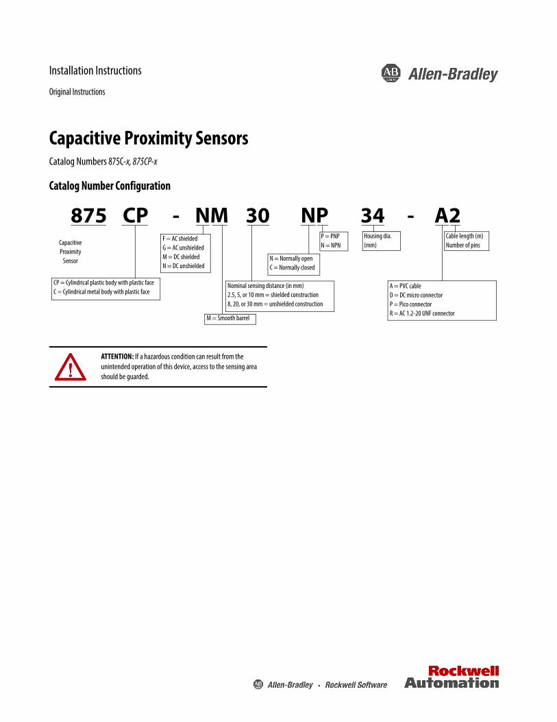
Capacitive Proximity SensorsCatalog Numbers 875C-x, 875CP-x
Catalog Number Configuration
ATTENTION: If a hazardous condition can result from the unintended operation of this device, access to the sensing area should be guarded.
875 CP - NM 30 NP 34 - A2Capacitive Proximity
Sensor
CP = Cylindrical plastic body with plastic faceC = Cylindrical metal body with plastic face
F = AC shieldedG = AC unshieldedM = DC shieldedN = DC unshielded
M = Smooth barrel
N = Normally openC = Normally closed
Nominal sensing distance (in mm)2.5, 5, or 10 mm = shielded construction8, 20, or 30 mm = unshielded construction
P = PNPN = NPN
Housing dia. (mm)
Cable length (m)Number of pins
A = PVC cableD = DC micro connectorP = Pico connectorR = AC 1.2-20 UNF connector

Capacitive Proximity Sensors
WiringAll external wiring should conform to the National Electric Code and applicable local codes. Connect the proximity switch to the power supply and load as shown in the wiring diagrams. If the positive (+) and the negative (-) wires are reversed, the switch will not operate properly. The sensor will not be damaged because it is equipped with reverse polarity protection.
Wiring Diagrams for AC Switches
Cable Micro ConnectorNormally Open or Normally Closed
Wiring Diagrams for DC Switches
CableNormally Open or Normally Closed
Micro connectorNormally Open or Normally Closed
Pico connectorNormally Open or Normally Closed
Terminal ChamberNormally Open or Normally Closed
Specifications—AC Models
Attribute ValueLoad current, maximum 300 mA
Inrush current 2 A
Leakage current ≤1.5 mA
Operating voltage 24…240V AC
Voltage drop ≤7.5V AC
Repeatability ≤10%
Hysteresis ≤20%
Switching frequency, maximum 25 Hz
Transient noise protection Incorporated
Enclosure NEMA 1, 3, 4, 6, 13; IP67Plastic or nickel-plated brass
Certifications UL CSA and CE Marked for all applicable directives; IEC 947-5-2
Connections Cable: 2 m (6.56 ft) length, 2-conductor PVCQuick-disconnect: 3-pin micro
Status indicators Green: Power; Yellow: Output
Operating Temperature [C (F)] -25…+70° (-13…+158°)
LoadLoad
Load
BlackBlue
Note: Load can be switched to pin 2.
+
+ 10…48V DC (12 mm)10…48V DC (18…34 mm)
--
--
+ --
--+
10…48V DC (12 mm)10…48V DC (18…34 mm)
BlueLoad
Black
Brown
PNP (Sourcing)NPN (Sinking)
Load
Brown
Blue
Black
Specifications—DC Models
Attribute ValueLoad current, maximum 300 mA
Leakage current --
Operating voltage 10…48V DC
Voltage drop <2V
Repeatability ≤10%
Hysteresis ≤20%
Switching frequency, maximum 100 Hz
Transient noise protection Incorporated
Reverse polarity protection Incorporated
Short circuit protection Incorporated
Overload protection Incorporated
Enclosure NEMA 1, 3, 4, 6, 13; IP67Plastic or nickel-plated brass
Certifications UL CSA and CE Marked for all applicable directives; IEC 947-5-2
Connections
Cable: 2 m (6.56 ft) length, 3-conductor PVCQuick-disconnect: 4-pin micro, 3-pin picoConduit opening: 1/2 14 NPT internal thread with screw terminals
Status indicators Green: Power; Yellow: Output
Operating Temperature [C (F)] -25…+70° (-13…+158°)
-- +
-- +
10…48V DC-- +
-- +
10…48V DC
Load
Load
PNP (Sourcing)NPN (Sinking)
Load
Load
PNP (Sourcing)NPN (Sinking)
--
+
--+ 10…48V DC
+
--
--+ 10…48V DC
LoadLoad
+
+10…48V DC
--
T3--
T1
T2
+ --
T1--+
T2
T3
10…48V DC
PNP (Sourcing)NPN (Sinking)
Load
2 Rockwell Automation Publication 875CP-IN001A-EN-P - April 2016
Capacitive Proximity Sensors
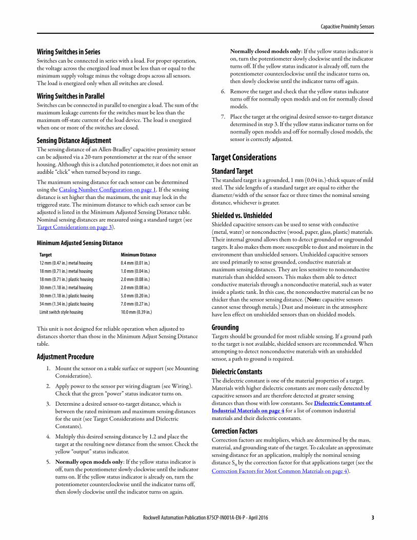
Wiring Switches in SeriesSwitches can be connected in series with a load. For proper operation, the voltage across the energized load must be less than or equal to the minimum supply voltage minus the voltage drops across all sensors. The load is energized only when all switches are closed.
Wiring Switches in ParallelSwitches can be connected in parallel to energize a load. The sum of the maximum leakage currents for the switches must be less than the maximum off-state current of the load device. The load is energized when one or more of the switches are closed.
Sensing Distance AdjustmentThe sensing distance of an Allen-Bradley® capacitive proximity sensor can be adjusted via a 20-turn potentiometer at the rear of the sensor housing. Although this is a clutched potentiometer, it does not emit an audible “click” when turned beyond its range.
The maximum sensing distance for each sensor can be determined using the Catalog Number Configuration on page 1. If the sensing distance is set higher than the maximum, the unit may lock in the triggered state. The minimum distance to which each sensor can be adjusted is listed in the Minimum Adjusted Sensing Distance table. Nominal sensing distances are measured using a standard target (see Target Considerations on page 3).
This unit is not designed for reliable operation when adjusted to distances shorter than those in the Minimum Adjust Sensing Distance table.
Adjustment Procedure1. Mount the sensor on a stable surface or support (see Mounting
Consideration).
2. Apply power to the sensor per wiring diagram (see Wiring). Check that the green “power” status indicator turns on.
3. Determine a desired sensor-to-target distance, which is between the rated minimum and maximum sensing distances for the unit (see Target Considerations and Dielectric Constants).
4. Multiply this desired sensing distance by 1.2 and place the target at the resulting new distance from the sensor. Check the yellow “output” status indicator.
5. Normally open models only: If the yellow status indicator is off, turn the potentiometer slowly clockwise until the indicator turns on. If the yellow status indicator is already on, turn the potentiometer counterclockwise until the indicator turns off, then slowly clockwise until the indicator turns on again.
Normally closed models only: If the yellow status indicator is on, turn the potentiometer slowly clockwise until the indicator turns off. If the yellow status indicator is already off, turn the potentiometer counterclockwise until the indicator turns on, then slowly clockwise until the indicator turns off again.
6. Remove the target and check that the yellow status indicator turns off for normally open models and on for normally closed models.
7. Place the target at the original desired sensor-to-target distance determined in step 3. If the yellow status indicator turns on for normally open models and off for normally closed models, the sensor is correctly adjusted.
Target ConsiderationsStandard TargetThe standard target is a grounded, 1 mm (0.04 in.)-thick square of mild steel. The side lengths of a standard target are equal to either the diameter/width of the sensor face or three times the nominal sensing distance, whichever is greater.
Shielded vs. UnshieldedShielded capacitive sensors can be used to sense with conductive (metal, water) or nonconductive (wood, paper, glass, plastic) materials. Their internal ground allows them to detect grounded or ungrounded targets. It also makes them more susceptible to dust and moisture in the environment than unshielded sensors. Unshielded capacitive sensors are used primarily to sense grounded, conductive materials at maximum sensing distances. They are less sensitive to nonconductive materials than shielded sensors. This makes them able to detect conductive materials through a nonconductive material, such as water inside a plastic tank. In this case, the nonconductive material can be no thicker than the sensor sensing distance. (Note: capacitive sensors cannot sense through metals.) Dust and moisture in the atmosphere have less effect on unshielded sensors than on shielded models.
GroundingTargets should be grounded for most reliable sensing. If a ground path to the target is not available, shielded sensors are recommended. When attempting to detect nonconductive materials with an unshielded sensor, a path to ground is required.
Dielectric ConstantsThe dielectric constant is one of the material properties of a target. Materials with higher dielectric constants are more easily detected by capacitive sensors and are therefore detected at greater sensing distances than those with low constants. See Dielectric Constants of Industrial Materials on page 4 for a list of common industrial materials and their dielectric constants.
Correction FactorsCorrection factors are multipliers, which are determined by the mass, material, and grounding state of the target. To calculate an approximate sensing distance for an application, multiply the nominal sensing distance Sn by the correction factor for that applications target (see the Correction Factors for Most Common Materials on page 4).
Minimum Adjusted Sensing Distance
Target Minimum Distance12 mm (0.47 in.) metal housing 0.4 mm (0.01 in.)
18 mm (0.71 in.) metal housing 1.0 mm (0.04 in.)
18 mm (0.71 in.) plastic housing 2.0 mm (0.08 in.)
30 mm (1.18 in.) metal housing 2.0 mm (0.08 in.)
30 mm (1.18 in.) plastic housing 5.0 mm (0.20 in.)
34 mm (1.34 in.) plastic housing 7.0 mm (0.27 in.)
Limit switch style housing 10.0 mm (0.39 in.)
Rockwell Automation Publication 875CP-IN001A-EN-P - April 2016 3
Capacitive Proximity Sensors
Environmental FactorsCapacitive sensors can be compromised by humidity and moisture on the sensor face. Oil or water droplets on the sensor face can cause the unit to become unstable. Dust and moisture in the atmosphere have less of an effect on unshielded sensors than on shielded models.
Mounting ConsiderationsThe sensor must be securely mounted on a firm, stable surface, or support. A mounting configuration, which is unstable or subject to excessive vibration, may cause intermittent operation.
Shielded vs. UnshieldedShielded sensors can be mounted flush with surrounding materials. Unshielded sensors must be mounted such that the area around the sensing face is free of any material, which could trigger the sensor. Minimum clearance in all directions should be equal to the diameter or width of the sensor.
Spacing Between DevicesWhen two shielded or unshielded sensors are facing each other, they must be mounted far apart to avoid interference. Minimum spacing should be eight times the housing diameter or width. When two shielded sensors are mounted side by side, the minimum distance between them must be greater than one diameter or width. When two unshielded sensors are mounted side by side, the distance between them should be at least four times their diameter or width. See Dimensions section for housing sizes.
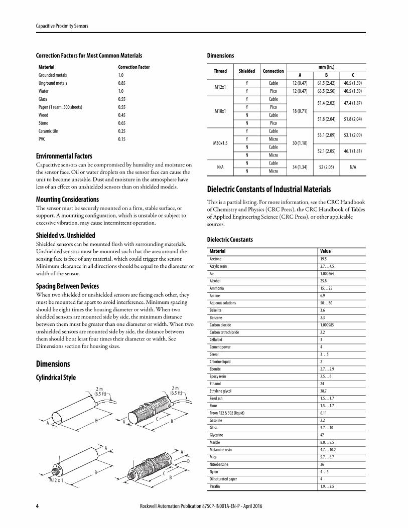
DimensionsCylindrical Style
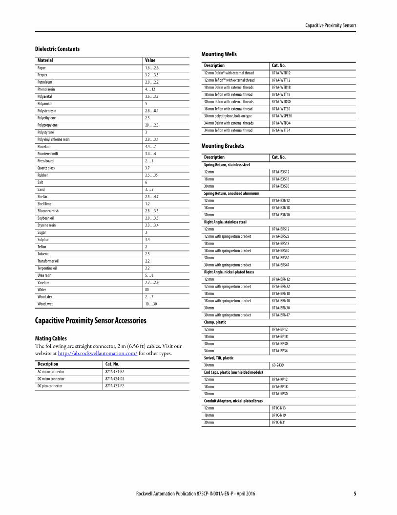
Dielectric Constants of Industrial MaterialsThis is a partial listing. For more information, see the CRC Handbook of Chemistry and Physics (CRC Press), the CRC Handbook of Tables of Applied Engineering Science (CRC Press), or other applicable sources.
Correction Factors for Most Common Materials
Material Correction FactorGrounded metals 1.0
Unground metals 0.85
Water 1.0
Glass 0.55
Paper (1 ream, 500 sheets) 0.55
Wood 0.45
Stone 0.65
Ceramic tile 0.25
PVC 0.15
D
A
BC
A B
2 m(6.5 ft)
C BA
2 m(6.5 ft)
M12 x 1
B
A
Dimensions
Thread Shielded Connectionmm (in.)
A B C
M12x1Y Cable 12 (0.47) 61.5 (2.42) 40.5 (1.59)
Y Pico 12 (0.47) 63.5 (2.50) 40.5 (1.59)
M18x1
Y Cable
18 (0.71)
51.4 (2.02) 47.4 (1.87)Y Pico
N Cable51.8 (2.04) 51.8 (2.04)
N Pico
M30x1.5
Y Cable
30 (1.18)
53.1 (2.09) 53.1 (2.09)Y Micro
N Cable52.1 (2.05) 46.1 (1.81)
N Micro
N/AN Cable
34 (1.34) 52 (2.05) N/AN Micro
Dielectric Constants
Material ValueAcetone 19.5
Acrylic resin 2.7…4.5
Air 1.000264
Alcohol 25.8
Ammonia 15…25
Aniline 6.9
Aqueous solutions 50…80
Bakelite 3.6
Benzene 2.3
Carbon dioxide 1.000985
Carbon tetrachloride 2.2
Celluloid 3
Cement power 4
Cereal 3…5
Chlorine liquid 2
Ebonite 2.7…2.9
Epoxy resin 2.5…6
Ethanol 24
Ethylene glycol 38.7
Fired ash 1.5…1.7
Flour 1.5…1.7
Freon R22 & 502 (liquid) 6.11
Gasoline 2.2
Glass 3.7…10
Glycerine 47
Marble 8.0…8.5
Melamine resin 4.7…10.2
Mica 5.7…6.7
Nitrobenzine 36
Nylon 4…5
Oil saturated paper 4
Parafin 1.9…2.5
4 Rockwell Automation Publication 875CP-IN001A-EN-P - April 2016
Capacitive Proximity Sensors
Capacitive Proximity Sensor Accessories
Paper 1.6…2.6
Perpex 3.2…3.5
Petroleum 2.0…2.2
Phenol resin 4…12
Polyacetal 3.6…3.7
Polyamide 5
Polyster resin 2.8…8.1
Polyethylene 2.3
Polypropylene 20.…2.3
Polystyrene 3
Polyvinyl chlorine resin 2.8…3.1
Porcelain 4.4…7
Powdered milk 3.4…4
Press board 2…5
Quartz glass 3.7
Rubber 2.5…35
Salt 6
Sand 3…5
Shellac 2.5…4.7
Shell lime 1.2
Silocon varnish 2.8…3.3
Soybean oil 2.9…3.5
Styrene resin 2.3…3.4
Sugar 3
Sulphur 3.4
Teflon 2
Toluene 2.3
Transformer oil 2.2
Terpentine oil 2.2
Urea resin 5…8
Vaseline 2.2…2.9
Water 80
Wood, dry 2…7
Wood, wet 10…30
Mating CablesThe following are straight connector, 2 m (6.56 ft) cables. Visit our website at http://ab.rockwellautomation.com/ for other types.
Description Cat. No.AC micro connector 871A-CS3-R2
DC micro connector 871A-CS4-D2
DC pico connector 871A-CS3-P2
Dielectric Constants
Material ValueMounting Wells
Description Cat. No.12 mm Delrin® with external thread 871A-WTD12
12 mm Teflon™ with external thread 871A-WTT12
18 mm Delrin with external threads 871A-WTD18
18 mm Teflon with external thread 871A-WTT18
30 mm Delrin with external threads 871A-WTD30
18 mm Teflon with external thread 871A-WTT30
30 mm polyethylene, bolt-on type 871A-WSPE30
34 mm Delrin with external threads 871A-WTD34
34 mm Teflon with external thread 871A-WTT34
Mounting Brackets
Description Cat. No.Spring Return, stainless steel
12 mm 871A-BXS12
18 mm 871A-BXS18
30 mm 871A-BXS30
Spring Return, anodized aluminum
12 mm 871A-BXN12
18 mm 871A-BXN18
30 mm 871A-BXN30
Right Angle, stainless steel
12 mm 871A-BRS12
12 mm with spring return bracket 871A-BRS22
18 mm 871A-BRS18
18 mm with spring return bracket 871A-BRS30
30 mm 871A-BRS30
30 mm with spring return bracket 871A-BRS47
Right Angle, nickel-plated brass
12 mm 871A-BRN12
12 mm with spring return bracket 871A-BRN22
18 mm 871A-BRN18
18 mm with spring return bracket 871A-BRN30
30 mm 871A-BRN30
30 mm with spring return bracket 871A-BRN47
Clamp, plastic
12 mm 871A-BP12
18 mm 871A-BP18
30 mm 871A-BP30
34 mm 871A-BP34
Swivel, Tilt, plastic
30 mm 60-2439
End Caps, plastic (unshielded models)
12 mm 871A-KP12
18 mm 871A-KP18
30 mm 871A-KP30
Conduit Adaptors, nickel-plated brass
12 mm 871C-N13
18 mm 871C-N19
30 mm 871C-N31
Rockwell Automation Publication 875CP-IN001A-EN-P - April 2016 5

Notes:
Allen-Bradley, Rockwell Automation, and Rockwell Software are trademarks of Rockwell Automation, Inc.
Trademarks not belonging to Rockwell Automation are property of their respective companies.
Rockwell Otomasyon Ticaret A.Ş., Kar Plaza İş Merkezi E Blok Kat:6 34752 İçerenköy, İstanbul, Tel: +90 (216) 5698400
Rockwell Automation maintains current product environmental information on its website athttp://www.rockwellautomation.com/rockwellautomation/about-us/sustainability-ethics/product-environmental-compliance.page.
Publication 875CP-IN001A-EN-P - April 2016 75021-119-01 Ver 02Copyright © 2016 Rockwell Automation, Inc. All rights reserved. Printed in the U.S.A.