Embed Size (px)
Citation preview

Capacitive Proximity Switches BCS R08RRE…
www.balluff.com english 1
Capacitive Proximity Switches
BCS R08RRE… MicroBox
User's Guide
english

Capacitive Proximity Switches BCS R08RRE…
2
Content
Validity ................................................................... 3
Notes to the user ................................................... 3
Symbols and conventions .......................................... 3
Downloading further instructions ............................. 3
Intended use .......................................................... 3
Safety notes ........................................................... 3
Product description ............................................... 4
Properties .................................................................. 4
Applications ............................................................... 4
Media overview ......................................................... 4
Scope of delivery ....................................................... 4
Electrical connection ............................................. 5
Installation ............................................................. 5
Installation location/environment ............................ 5
Installation options ................................................ 6
Sensor installation without bracket .......................... 6
Installation with bracket ............................................ 6
Leakage application ................................................... 7
Bracket installation on a tube ................................... 7
Installation with BALLUFF installation system ........... 7
Operation............................................................... 8
Operating elements ................................................... 8
Display ....................................................................... 8
Calibration ................................................................. 8
Calibration for object recognition ............................. 8
Calibration for fill level detection .............................. 9
Calibration for leakage application............................ 9
Operation with IO-Link .......................................... 9
Switching output in SIO mode ................................... 9
Adjustable hysteresis ................................................. 9
Adjustable delay ........................................................ 9
Adjustable filter ......................................................... 9
Maintenance .......................................................... 9
Disposal ................................................................. 9
Technical data ...................................................... 11
Ordering information .......................................... 12
Type code ................................................................ 12
Available devices ..................................................... 12
Accessories .............................................................. 13
IO-Link .................................................................. 13
General .................................................................... 13
Profiles and features ............................................... 13
Process data ............................................................ 13
Parameters .............................................................. 14
System commands .................................................. 15

Capacitive Proximity Switches BCS R08RRE…
www.balluff.com english 3
Validity
This guide applies to capacitive proximity switches
of the BCS R08RRE product family.
Notes to the user
The guide is intended for qualified technical
personnel. Read this guide before installing and
operating the device.
Symbols and conventions
� Instruction
Important note
→ Information
Downloading further instructions
You can find this user's guide as well as further
information on the Internet at www.balluff.com
Intended use
Series BCS R08RRE proximity switches can be used
for object recognition or fill level detection.
Flawless function in accordance with the
specifications in the technical data is ensured only
when using original BALLUFF accessories. Use of
any other components will void the warranty.
Modifications to the sensor or non-approved use
are not permitted and will result in the loss of
warranty and liability claims against the
manufacturer.
Safety notes
The device may not be used in applications
where personal safety depends on proper
function of the device (not designed in
accordance with EU Machinery Directive).
Installation and startup may only be performed by
trained specialists with basic electrical knowledge.
The operator is responsible for ensuring that local
safety regulations are observed. The operator
must take steps to ensure that a defect in the
device will not result in hazards to persons or
equipment. If defects and unresolvable faults
occur in the device, take it out of service and
secure against unauthorized use.

Capacitive Proximity Switches BCS R08RRE…
4
Product description
Properties
Sensors from the product family BCS R08RRE
function based on the capacitive measuring
principle. This product family features devices
with two measurement technologies:
• Devices with standard technology can be used
for object recognition of conductive and non-
conductive media such as synthetic granules,
wood, etc.
• Devices featuring the patented SmartLEVEL
technology are used for fill level detection of
conductive liquids, even with build-up and
frothing.
Discrete outputs or IO-Link interface are available
for either technology (see section Available
devices).
Further characteristics of this product family:
• Switch point is teachable via DI-(white cable
to L+) or IO-Link.
• LED displays "Output function" and "Power
on"
• Protection from short circuit, voltage reversal,
and polarity reversal
• Approvals: CE, UL
For IO-Link devices, additional parameters are
available for setting behavior, see section
Operation with IO-Link.
Applications
Some example applications are:
• Object detection
• Stacking height recognition
• Fill level detection through the tank wall
• Leackage detection (except SmartLEVEL
versions)
Media overview
The device can be used to query virtually all liquid,
paste-like, granular, or powdery media. Examples
are listed in the following table.
Medium Object
recognition
and fill level
detection
with
standard
technology
Fill level
detection
with
SmartLEVEL
technology
Water •
Milk •
Wood, wood
pellets, paper,
cardboard
•
Plastics,
synthetic granules
•
Oils (mineral, food) •
Metals • •
Aqueous solutions
acids, alkaline
solutions
•
Leakage •
� We recommend an application test with
material samples.
Scope of delivery
• Capacitive sensor
• Mounting bracket
• Assembly instructions
The enclosed bracket can be used for mounting
the sensor on tubes or for leakage monitoring, for
example. The snap lock allows for quick sensor
replacement.
Capacitive Proximity Switches BCS R08RRE…
www.balluff.com english 5
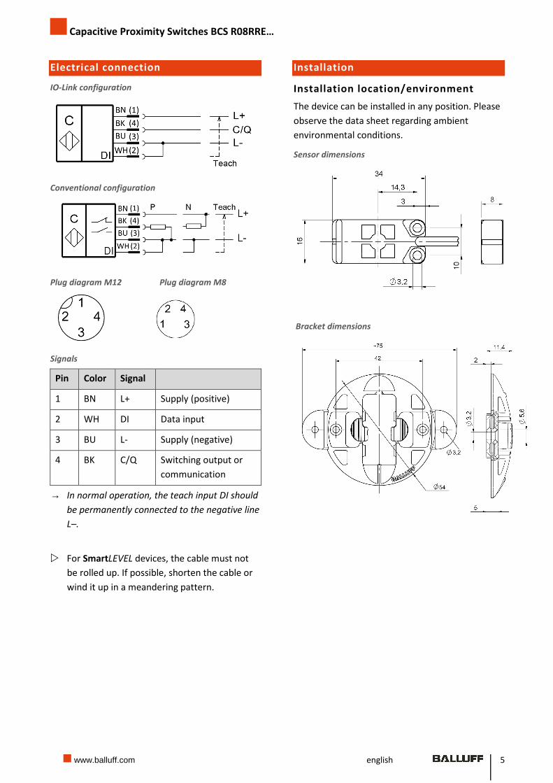
Electrical connection
IO-Link configuration
Conventional configuration
Plug diagram M12 Plug diagram M8
Signals
Pin Color Signal
1 BN L+ Supply (positive)
2 WH DI Data input
3 BU L- Supply (negative)
4 BK C/Q Switching output or
communication
→ In normal operation, the teach input DI should
be permanently connected to the negative line
L–.
� For SmartLEVEL devices, the cable must not
be rolled up. If possible, shorten the cable or
wind it up in a meandering pattern.
Installation
Installation location/environment
The device can be installed in any position. Please
observe the data sheet regarding ambient
environmental conditions.
Sensor dimensions
Bracket dimensions
Capacitive Proximity Switches BCS R08RRE…
6
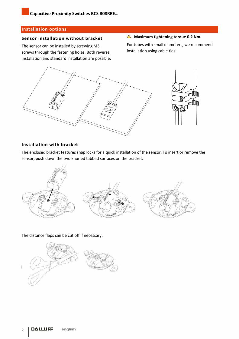
Installation options
Sensor installation without bracket
The sensor can be installed by screwing M3
screws through the fastening holes. Both reverse
installation and standard installation are possible.
Maximum tightening torque 0.2 Nm.
For tubes with small diameters, we recommend
installation using cable ties.
Installation with bracket
The enclosed bracket features snap locks for a quick installation of the sensor. To insert or remove the
sensor, push down the two knurled tabbed surfaces on the bracket.
The distance flaps can be cut off if necessary.

Capacitive Proximity Switches BCS R08RRE…
www.balluff.com 7
Leakage application
The bracket can also be used for leakage detection. To install the sensor with a distance of 2 mm from the
floor fold the distance flaps under the bracket until they click into the locked position.
Bracket installation on a tube
Installation with horizontal cable exit Installation with vertical cable exit
For large tube diameters or containers, we recommend a strap.
Installation with BALLUFF installation system

Capacitive Proximity Switches BCS R08RRE…
8
Operation
Operating elements
View from below
1) Active surface
2) Switching state display - yellow
3) Power on - green
4) Fastening holes
Display
The switching state display (yellow) is illuminated
when the output is active.
With IO-Link devices, the switching function is
defined via the "Switch Point Mode.Logic"
parameter.
The power on display is constantly illuminated in
normal operation. If there is a malfunction, for
example overload at the output, the display
flashes.
Also see Display during calibration.
Calibration
The switch point can be taught via the DI (Data
Input) teach input for either empty or full vessel
conditions.
For a full calibration, the switch point is set below
the current sensor value. That way, the active
status can be recognized even if there are slight
changes in the application.
Accordingly, for an empty calibration the switch
point is set above the current sensor value.
In most applications, full calibration is usually
sufficient. For a secure switch-off despite any
present residues and build-up, empty calibration
can be performed in critical applications.
Calibration via teach line (DI input)
Calibration is started by connecting the DI input to
L+; the switching threshold is adopted when
removing the DI input from L+. The type of
calibration is determined based on the duration;
the process is displayed via the function LED (see
Display during calibration).
� Full calibration: Connect the DI input to L+ for
2 to 7 seconds
� Empty calibration: Connect the DI input to L+
for 7 to 12 seconds
If the DI input remains connected to L+ for longer
than 12 seconds, the calibration process is
aborted. The switching threshold is not changed.
To start a new calibration, the DI input must be
removed from L+.
→ For IO-Link devices, the DI teach input can be
deactivated via the "Device Access Lock. Local
parametrization" parameter.
Display during calibration
• During the full calibration (2 to 7 seconds
after DI active) the ready LED flashes slowly.
The switching state LED is OFF.
• During the empty calibration (7 to 12 seconds
after DI active) the ready LED flashes slowly.
The switching state LED is ON.
• If the calibration is successful, the switching
state LED flashes slowly three times. During
this, the ready LED is OFF.
• If the calibration process is canceled (DI active
for longer than 12 seconds) or if there is an
error, the switching state LED flashes quickly
several times. During this, the ready LED is
OFF.
Calibration for object recognition
Move the object into the desired switching range.
Observe the permissible detection range of the
sensor as well as reduction factors depending on
the application!
Capacitive Proximity Switches BCS R08RRE…
www.balluff.com 9
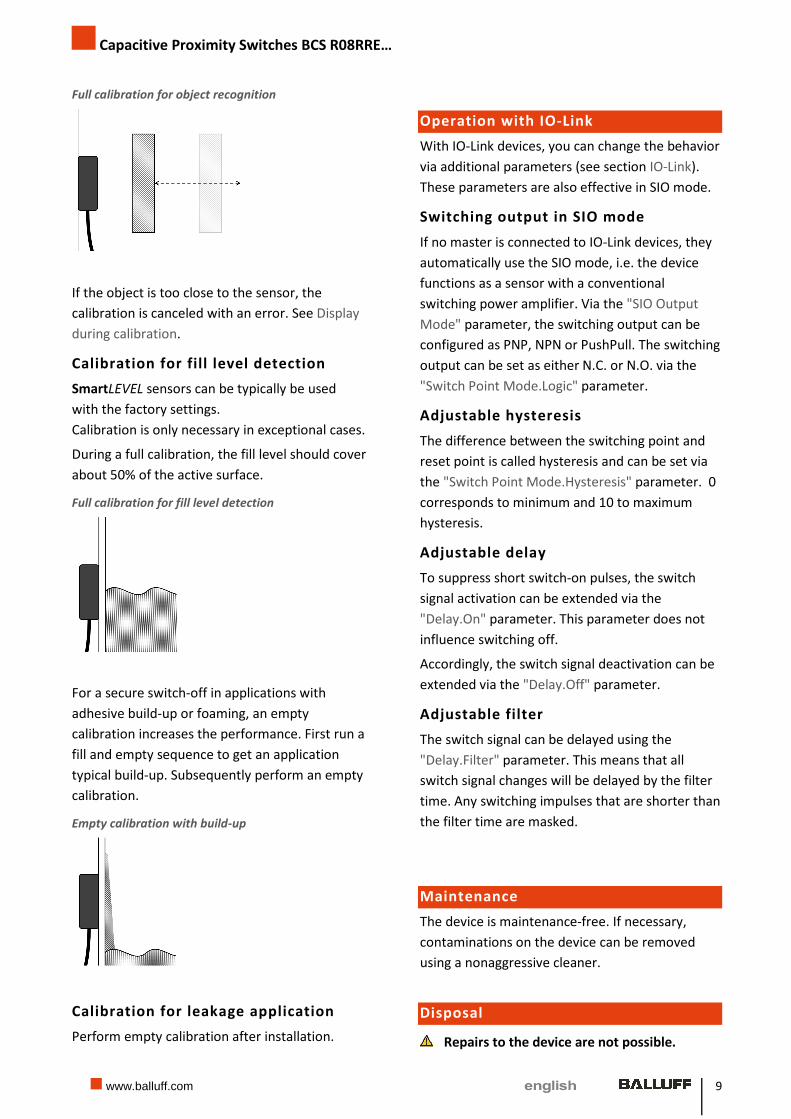
Full calibration for object recognition
If the object is too close to the sensor, the
calibration is canceled with an error. See Display
during calibration.
Calibration for fill level detection
SmartLEVEL sensors can be typically be used
with the factory settings.
Calibration is only necessary in exceptional cases.
During a full calibration, the fill level should cover
about 50% of the active surface.
Full calibration for fill level detection
For a secure switch-off in applications with
adhesive build-up or foaming, an empty
calibration increases the performance. First run a
fill and empty sequence to get an application
typical build-up. Subsequently perform an empty
calibration.
Empty calibration with build-up
Calibration for leakage application
Perform empty calibration after installation.
Operation with IO-Link
With IO-Link devices, you can change the behavior
via additional parameters (see section IO-Link).
These parameters are also effective in SIO mode.
Switching output in SIO mode
If no master is connected to IO-Link devices, they
automatically use the SIO mode, i.e. the device
functions as a sensor with a conventional
switching power amplifier. Via the "SIO Output
Mode" parameter, the switching output can be
configured as PNP, NPN or PushPull. The switching
output can be set as either N.C. or N.O. via the
"Switch Point Mode.Logic" parameter.
Adjustable hysteresis
The difference between the switching point and
reset point is called hysteresis and can be set via
the "Switch Point Mode.Hysteresis" parameter. 0
corresponds to minimum and 10 to maximum
hysteresis.
Adjustable delay
To suppress short switch-on pulses, the switch
signal activation can be extended via the
"Delay.On" parameter. This parameter does not
influence switching off.
Accordingly, the switch signal deactivation can be
extended via the "Delay.Off" parameter.
Adjustable filter
The switch signal can be delayed using the
"Delay.Filter" parameter. This means that all
switch signal changes will be delayed by the filter
time. Any switching impulses that are shorter than
the filter time are masked.
Maintenance
The device is maintenance-free. If necessary,
contaminations on the device can be removed
using a nonaggressive cleaner.
Disposal
Repairs to the device are not possible.

Capacitive Proximity Switches BCS R08RRE…
10
� The device must be disposed of in accordance
with the European Directives 2002/96/EC and
2003/108/EC (Waste Electrical and Electronic
Equipment). Old devices may not be disposed
of with household waste!
� Observe the national regulations for disposal.
Capacitive Proximity Switches BCS R08RRE…
www.balluff.com 11
Technical data
Refer to the datasheet for the latest technical information.
Electric data
Supply voltage UB
- Conventional
- IO-Link
12 to 30 V DC
18 to 30 V DC
Rated operating voltage Ue 24 V DC
Current draw (no-load) I0 < 12 mA
Switching current Ie ≤ 50 mA
Switching frequency f
- Standard technology
- SmartLEVEL
≤ 50 Hz
≤ 10 Hz
Voltage drop ≤ 1.5 V
Mechanical data
Ambient temperature –25 to +70°C
Dimensions L x W x H 34 x 16 x 10 mm
Housing material PP
Degree of protection IP67
Tightening torque
(M3 screws in fastening holes)
≤ 0.2 Nm
IO-Link
IO-Link revision 1.1
Transfer rate 38.4 kBit/s (COM2)
Minimum cycle time 5.0 ms
Vendor ID 0x0378 (888)
Device ID BCS R08RRE-...
-..PIM80C-EP00,3-GS04
-..PIMFHC-EP00,3-GS04
0x070203 (459267)
0x070204 (459268)
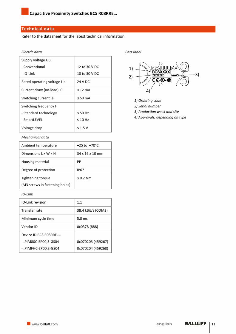
Part label
1) Ordering code
2) Serial number
3) Production week and site
4) Approvals, depending on type

Capacitive Proximity Switches BCS R08RRE…
12
Ordering information
Type code
Power amplifier
PS = PNP N.O.
PO = PNP N.C.
NS = NPN N.O.
NO = NPN N.C.
PI = IO-Link
Technology
80 = standard technology
FH = SmartLEVEL technology
Cable length
2 = 2m
0,3 = 0.3 m
Plug
Empty = cable connection
GS75 = M8, 4-pin
GS04 = M12, 4-pin
Available devices
Type designation Ordering
code
Description
BCS R08RRE-PSM80C-EP02 BCS012A Standard, PNP N.O., 2 m cable with open end
BCS R08RRE-POM80C-EP02 BCS012C Standard, PNP N.C., 2 m cable with open end
BCS R08RRE-NSM80C-EP02 BCS012E Standard, NPN N.O., 2 m cable with open end
BCS R08RRE-NOM80C-EP02 BCS012F Standard, NPN N.C., 2 m cable with open end
BCS R08RRE-PSM80C-EP00,3-GS75 BCS012T Standard, PNP N.O., 0.3 m cable with M8 plug, 4-pin
BCS R08RRE-POM80C-EP00,3-GS75 BCS012U Standard, PNP N.C., 0.3 m cable with M8 plug, 4-pin
BCS R08RRE-NSM80C-EP00,3-GS75 BCS012W Standard, NPN N.O., 0.3 m cable with M8 plug, 4-pin
BCS R08RRE-NOM80C-EP00,3-GS75 BCS012Y Standard, NPN N.C., 0.3 m cable with M8 plug, 4-pin
BCS R08RRE-PSMFHC-EP02 BCS012H SmartLEVEL, PNP N.O., 2 m cable with open end
BCS R08RRE-POMFHC-EP02 BCS012J SmartLEVEL, PNP N.C., 2 m cable with open end
BCS R08RRE-NSMFHC-EP02 BCS012K SmartLEVEL, NPN N.O., 2 m cable with open end
BCS R08RRE-NOMFHC-EP02 BCS012L SmartLEVEL, NPN N.C., 2 m cable with open end
BCS R08RRE-PSMFHC-EP00,3-GS75 BCS012Z SmartLEVEL, PNP N.O., 0.3 m cable with M8 plug, 4-pin
BCS R08RRE-POMFHC-EP00,3-GS75 BCS0130 SmartLEVEL, PNP N.C., 0.3 m cable with M8 plug, 4-pin
BCS R08RRE-NSMFHC-EP00,3-GS75 BCS0131 SmartLEVEL, NPN N.O., 0.3 m cable with M8 plug, 4-pin
BCS R08RRE-NOMFHC-EP00,3-GS75 BCS0132 SmartLEVEL, NPN N.C., 0.3 m cable with M8 plug, 4-pin
BCS R08RRE-PIM80C-EP00,3-GS04 BCS012N Standard, IO-Link, 0.3 m cable with M12 plug, 4-pin
BCS R08RRE-PIMFHC-EP00,3-GS04 BCS012P SmartLEVEL, IO-Link, 0.3 m cable with M12 plug, 4-pin
BCS R08RRE – PS M 80 C-EP0 0,3 - GS75
Capacitive Proximity Switches BCS R08RRE…
www.balluff.com 13
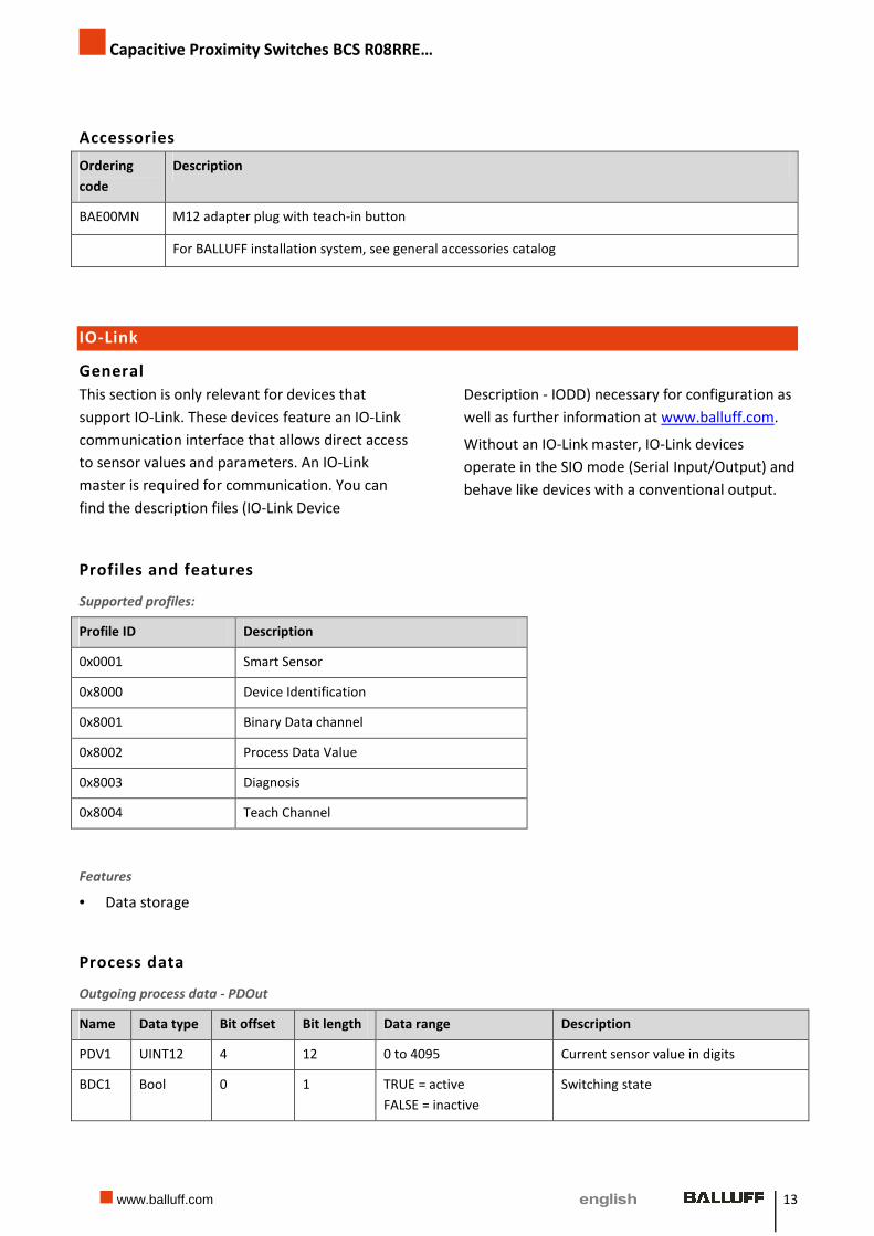
Accessories
Ordering
code
Description
BAE00MN M12 adapter plug with teach-in button
For BALLUFF installation system, see general accessories catalog
IO-Link
General
This section is only relevant for devices that
support IO-Link. These devices feature an IO-Link
communication interface that allows direct access
to sensor values and parameters. An IO-Link
master is required for communication. You can
find the description files (IO-Link Device
Description - IODD) necessary for configuration as
well as further information at www.balluff.com.
Without an IO-Link master, IO-Link devices
operate in the SIO mode (Serial Input/Output) and
behave like devices with a conventional output.
Profiles and features
Supported profiles:
Profile ID Description
0x0001 Smart Sensor
0x8000 Device Identification
0x8001 Binary Data channel
0x8002 Process Data Value
0x8003 Diagnosis
0x8004 Teach Channel
Features
• Data storage
Process data
Outgoing process data - PDOut
Name Data type Bit offset Bit length Data range Description
PDV1 UINT12 4 12 0 to 4095 Current sensor value in digits
BDC1 Bool 0 1 TRUE = active
FALSE = inactive
Switching state

Capacitive Proximity Switches BCS R08RRE…
14
Parameters
Index Name Data type Sub-
index
Access Data range Description
2 System Command UINT8 W See section System
commands
12 Device Access
Locks
UINT16 R/W Access is blocked if the bit =
TRUE
- Bit0 TRUE, FALSE Write parameter
- Bit 1 TRUE, FALSE Data storage
- Bit 2 TRUE, FALSE Local parametrization
16 Vendor Name String R "BALLUFF"
17 Vendor Text String R "www.balluff.com"
18 Product Name String R Type code, depending on
type
19 Product ID String R Ordering code, depending
on type
20 Product Text String R Device description,
depending on type
21 Serial Number String R Serial number
22 Hardware Revision String R Hardware version
23 Firmware Revision String R Firmware version
24 Application Specific
Tag
String R/W max. 32 characters
default = „“
Description of application,
e.g. installation location
36 Device Status UINT8 R 0 – Device OK
2 – Out of Specification
4 – Failure
Device status
60 Setpoints BDC1 Array
- SP1 UINT16 1 R/W 0 to 4095 Switchpoint SP1
- SP2 UINT16 2 R/W 0 to 4095 Switchpoint SP2 is not used
and is always read as 0
61 Switch Point Mode Array
- Logic UINT8 1 R/W 0 – Normally Open,
1 – Normally Closed
default = 0
Switching function
- Mode UINT8 2 R 1 – Single Point Mode Operating mode
switchpoint
- Hysteresis UINT8 3 R/W 0 to 10, default = 5 Hysteresis switchpoint
178 Delay Array

Capacitive Proximity Switches BCS R08RRE…
www.balluff.com 15
Index Name Data type Sub-
index
Access Data range Description
- On UINT8 1 R/W Standard: 0 to 1280
SmartLEVEL: 0 to 2560
default = 0
Delay ON (in ms)
- Off UINT8 2 R/W See Delay.On Delay OFF (in ms)
- Filter UINT8 3 R/W See Delay.On Filter time (in ms)
180 SIO Output Mode UINT8 R/W 1 – PNP, default
2 – NPN
3 – PushPull
Switching output type
Switching function is
indicated in Switch Point
Mode.Logic
System commands
Value Name Description
77 Teach Full Full calibration
78 Teach Empty Empty calibration
128 Device Reset Restart device
130 Factory Reset Reset factory defaults
163 Restore BDC Restore settings for switchpoint (BDC)

Capacitive Proximity Switches BCS R08RRE…
16
Balluff GmbH
Schurwaldstrasse 9
73765 Neuhausen a.d.F.
Phone +49 (0) 71 58/1 73-0
Fax +49 (0) 71 58/50 10
www.balluff.com
Do
c. n
o.
91
78
88
-72
6 E
N
01
11
94
85
C
15
:
Su
bje
ct t
o m
od
ific
ati
on
re
pla
ces
ed
itio
n A
15


![Osiprox Proximity Switches [Orig]](https://img.pdfslide.net/doc/110x75/551448724979591b1e8b4617/osiprox-proximity-switches-orig.jpg)