Embed Size (px)
Citation preview

teledynelecroy.com/waveprohd
Longest Memory Capture and navigate up to 5 Gpt records
Deepest Toolbox Powerful signal analysis accelerates insight
HD4096 Technology 12-bit resolution with 8 GHz bandwidth
2.5 GHz - 8 GHzHigh Definition Oscilloscopes
CAPTURE EVERY DETAIL

DeepToolbox
WavePro HD
has the greatest
breadth and depth
of tools to simplify
any debug task.
2
LongMemory
HD4096 technology
enables 12 bits of vertical resolution
with 8 GHz bandwidth
• Clean, Crisp Waveforms
• More Signal Details
• Unmatched Measurement Precision
HD4096High Definition Technology
Up to 5 Gpts of acquisition
memory means exceptionally
long capture times at full
sample rate and resolution.
Intuitive navigation tools
make it easy to find events of
interest and simplify analysis
of long waveforms.

Faster Time to Insight
Insight alone is not enough.
Markets and technologies change too rapidly.
The timing of critical design decisions is significant.
Faster Time to Insight is what matters.
3
8 GHz, 20 GS/s, 5 Gpts.12 bits all the time.
Capture Every Detail.

4
HD4096 TECHNOLOGY - 16X CLOSER TO PERFECT
Teledyne LeCroy high definition 12-bit oscilloscopes use unique HD4096 technology to provide superior and uncompromised measurement performance: – 12-bit ADCs with high sample rates – High signal-to-noise amplifiers – Low noise system architecture (to 8 GHz)
Oscilloscopes with HD4096 technology have higher resolution than conventional 8-bit oscilloscopes (4096 vs. 256 vertical levels) and low noise for uncompromised measurement performance. The 12-bit ADCs support capture of fast signals and oscilloscope bandwidth ratings up to 8 GHz, while 20 GS/s sample rate ensures the highest measurement accuracy and precision. The high performance input amplifiers deliver pristine signal fidelity, and the low-noise system architecture provides an ideal signal path to ensure that signal details are delivered accurately to the oscilloscope display – 16x closer to perfect.
16x more resolutionHD4096 technology provides 12 bits of vertical resolution with 16x more resolution compared to conventional 8-bit oscilloscopes. The 4096 discrete vertical levels reduce the quantization error compared to 256 vertical levels. This improves the accuracy and precision of the signal capture and increases measurement confidence.
16x Closer to Perfect HD4096 12-bit oscilloscope
Conventional 8-bit oscilloscope
Analog signal
5
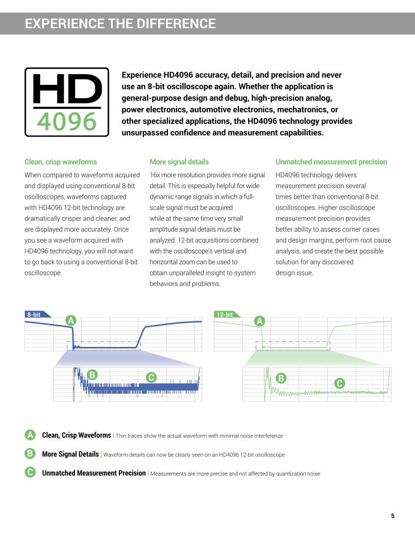
EXPERIENCE THE DIFFERENCE
Clean, crisp waveforms
When compared to waveforms acquired and displayed using conventional 8-bit oscilloscopes, waveforms captured with HD4096 12-bit technology are dramatically crisper and cleaner, and are displayed more accurately. Once you see a waveform acquired with HD4096 technology, you will not want to go back to using a conventional 8-bit oscilloscope.
More signal details
16x more resolution provides more signal detail. This is especially helpful for wide dynamic range signals in which a full-scale signal must be acquired while at the same time very small amplitude signal details must be analyzed. 12-bit acquisitions combined with the oscilloscope’s vertical and horizontal zoom can be used to obtain unparalleled insight to system behaviors and problems.
Unmatched measurement precision
HD4096 technology delivers measurement precision several times better than conventional 8-bit oscilloscopes. Higher oscilloscope measurement precision provides better ability to assess corner cases and design margins, perform root cause analysis, and create the best possible solution for any discovered design issue.
Experience HD4096 accuracy, detail, and precision and never use an 8-bit oscilloscope again. Whether the application is general-purpose design and debug, high-precision analog, power electronics, automotive electronics, mechatronics, or other specialized applications, the HD4096 technology provides unsurpassed confidence and measurement capabilities.
8-bit 12-bit
A
A A
B BC C
B
C
Clean, Crisp Waveforms | Thin traces show the actual waveform with minimal noise interference
Unmatched Measurement Precision | Measurements are more precise and not affected by quantization noise
More Signal Details | Waveform details can now be clearly seen on an HD4096 12-bit oscilloscope

6
LONG MEMORY, NO COMPROMISE
With up to 5 Gpts of acquisition memory, WavePro HD 12-bit oscilloscopes capture events occurring over long periods of time, while still maintaining high sample rate for visibility into the smallest details.
Longest memory WavePro HD oscilloscopes contain a sophisticated acquisition and memory management architecture that makes 5 Gpt acquisitions fast and responsive. More memory means more visibility into system behavior.
Simple navigation Long memory and high sample rates capture both millisecond-scale trends and picosecond-scale glitches. WavePro HD oscilloscopes are equipped with an advanced user interface that makes it easy to find features, navigate directly using timebase scale and position knobs, or set up zoom traces - whichever you prefer. Apply analysis tools easily to any type of trace.
No compromise WavePro HD can acquire 250 ms of data at full 20 GS/s sample rate - and always with 12 bits of resolution. Oscilloscopes with less memory require trading off sample rate for acquisition time.
0 50 100 150 200 250
time (ms)
Competitor B, 20 GS/s 40 ms acquisition time
Competitor A, 20 GS/s 100 ms acquisition time
WavePro HD 5 Gpts @ 20 GSs/s 250 ms acquisition time

7
LONG MEMORY, NO COMPROMISE POWERFUL, DEEP TOOLBOX
Our heritageTeledyne LeCroy’s 50+ year heritage is in processing long records to extract meaningful insight. We invented the digital oscilloscope and many of the additional waveshape analysis tools.
Our obsession Our tools and operating philosophy are standardized across much of our product line. This deep toolbox inspires insight; and your moment of insight is our reward.
Our invitation Our Periodic Table of Oscilloscope Tools explains the toolsets that Teledyne LeCroy has deployed in our oscilloscopes. Visit our interactive website to learn more about them. teledynelecroy.com/tools
WavePro HD Competitor A Competitor B

8
DEEPLY EMBEDDED COMPUTING SYSTEMS TESTING
WavePro HD has unsurpassed capabilities to acquire the longest records at the highest resolution for the most comprehensive deeply embedded computing system (analog, digital, serial data and sensor) testing.
Powerful, deep toolboxMore standard math, measure, pass/fail and other toolsets provide faster and more complete insight into circuit problems. Many additional application packages are optionally available to enhance understanding.
Superior serial data toolsets Comprehensive low-speed serial data triggers and decoders, plus measure/graph and eye diagram testing, provide the best causal analysis. Powerful serial data jitter analysis toolsets and compliance packages simplify complex validation.
Comprehensive probe offering A wide selection of low voltage, high voltage and current probes will accurately measure every signal in your circuit. New 8 GHz ProBus2 interface is backwards-compatible to the 20+ year legacy of ProBus-compatible probes.
System Power
DCDC
Buck
Embedded System High-speed MCU
Flash Memory
+12 Vdc Supply
Power Management
IC (PMIC)
DRAM (DDR) Memory Control
Interface
Power Management
Interface (I2C, PMbus,
SMbus, SPMI)
EEPROM VCORE
OscillatorDRAM Memory (DDR, LPDDR)
DRAM Memory (DDR, LPDDR)
DCDC
LDO
Memory Power
DCDC
LDO
DCDC
LDO
DCDC
LDO
InitializeReset
Power ON ResetTrigger In/Out
Timer/Counter
12-bit ADC
I2C
SPI
I2S
I2C
SPI or QSPI
CAN FDFlexRayUART1000
Base-TGPIOPWM USB 2.0
CAN FDPHY
FlexRayPHY
UARTPHY
1000Base-T
PHY
USB 2.0PHY
High-Speed Serial Data
Small LCD Driver
Audio Output
ROM BIOS
DCDC
LDO
Interrupt
Sensor/Actuator
Control Device
Actuator
Shift Register
VCC-AVCC-A VCC-PLL
DCDC
BuckDC
DC
BuckDC
DC
BuckDC
DC
BuckDC
DC
BuckDC
DC
BuckDC
DC
Buck
CKIN
Peripherals PowerBoost Buck Buck Buck
DCDC
DCDC
DCDC
DCDC
12-bit ADC
SPI
SPI
Analog Signal
PWM Signal
Serial Data SignalParallel Data Bus
Analog Device
Digital Device
Power Conversion Device
Mixed Signal Device
High-speed Serial PHY
CKOUTVSS
Power Rail
Digital Signal
DCDC
LDODC
DC
LDODC
DC
LDO
Serial Data Phy
Analog Sensor
SPI
Key
Analog Sensor

9
DEEPLY EMBEDDED COMPUTING SYSTEMS TESTING POWER INTEGRITY DEBUG AND VALIDATION
WavePro HD's combination of high bandwidth and high resolution provides the capability to validate and debug all aspects of power supply, delivery and consumption - ensuring complete confidence.
On-die ground bounceWavePro HD's high bandwidth means accurate characterization of high-speed on-die effects such as ground bounce, while its exceptionally low noise enables identification and root-cause analysis of low-level noise sources.
Find sources of PDN noiseSensitive measurements such as rail collapse characterization can be made with complete confidence thanks to WavePro HD's high dynamic range and 0.5% gain accuracy. And its low noise floor enables extremely detailed spectral analysis of the PDN noise environment.
Specialized power probes The combination of WavePro HD and the RP4030 4 GHz Power Rail Probe gives unsurpassed insight into PDN behavior over the widest available bandwidth. A variety of probe tips ensure easy connectivity.
System Power
DCDC
Buck
Embedded System High-speed MCU
Flash Memory
+12 Vdc Supply
Power Management
IC (PMIC)
DRAM (DDR) Memory Control
Interface
Power Management
Interface (I2C, PMbus,
SMbus, SPMI)
EEPROM VCORE
OscillatorDRAM Memory (DDR, LPDDR)
DRAM Memory (DDR, LPDDR)
DCDC
LDO
Memory Power
DCDC
LDO
DCDC
LDO
DCDC
LDO
InitializeReset
Power ON ResetTrigger In/Out
Timer/Counter
12-bit ADC
I2C
SPI
I2S
I2C
SPI or QSPI
CAN FDFlexRayUART1000
Base-TGPIOPWM USB 2.0
CAN FDPHY
FlexRayPHY
UARTPHY
1000Base-T
PHY
USB 2.0PHY
High-Speed Serial Data
Small LCD Driver
Audio Output
ROM BIOS
DCDC
LDO
Interrupt
Sensor/Actuator
Control Device
Actuator
Shift Register
VCC-AVCC-A VCC-PLL
DCDC
BuckDC
DC
BuckDC
DC
BuckDC
DC
BuckDC
DC
BuckDC
DC
BuckDC
DC
Buck
CKIN
Peripherals PowerBoost Buck Buck Buck
DCDC
DCDC
DCDC
DCDC
12-bit ADC
SPI
SPI
Analog Signal
PWM Signal
Serial Data SignalParallel Data Bus
Analog Device
Digital Device
Power Conversion Device
Mixed Signal Device
High-speed Serial PHY
CKOUTVSS
Power Rail
Digital Signal
DCDC
LDODC
DC
LDODC
DC
LDO
Serial Data Phy
Analog Sensor
SPI
Key
Analog SensorSystem Power
DCDC
Buck
Embedded System High-speed MCU
Flash Memory
+12 Vdc Supply
Power Management
IC (PMIC)
DRAM (DDR) Memory Control
Interface
Power Management
Interface (I2C, PMbus,
SMbus, SPMI)
EEPROM VCORE
OscillatorDRAM Memory (DDR, LPDDR)
DRAM Memory (DDR, LPDDR)
DCDC
LDO
Memory Power
DCDC
LDO
DCDC
LDO
DCDC
LDO
InitializeReset
Power ON ResetTrigger In/Out
Timer/Counter
12-bit ADC
I2C
SPI
I2S
I2C
SPI or QSPI
CAN FDFlexRayUART1000
Base-TGPIOPWM USB 2.0
CAN FDPHY
FlexRayPHY
UARTPHY
1000Base-T
PHY
USB 2.0PHY
High-Speed Serial Data
Small LCD Driver
Audio Output
ROM BIOS
DCDC
LDO
Interrupt
Sensor/Actuator
Control Device
Actuator
Shift Register
VCC-AVCC-A VCC-PLL
DCDC
BuckDC
DC
BuckDC
DC
BuckDC
DC
BuckDC
DC
BuckDC
DC
BuckDC
DC
Buck
CKIN
Peripherals PowerBoost Buck Buck Buck
DCDC
DCDC
DCDC
DCDC
12-bit ADC
SPI
SPI
Analog Signal
PWM Signal
Serial Data SignalParallel Data Bus
Analog Device
Digital Device
Power Conversion Device
Mixed Signal Device
High-speed Serial PHY
CKOUTVSS
Power Rail
Digital Signal
DCDC
LDODC
DC
LDODC
DC
LDO
Serial Data Phy
Analog Sensor
SPI
Key
Analog Sensor

10
SERIAL DATA JITTER AND NOISE ANALYSIS
WavePro HD 12-bit oscilloscopes bring the high signal fidelity of HD4096 technology to high-speed serial data analysis, enabling precise measurements with exceptionally low noise and jitter.
High precision, low jitterWavePro HD's 12-bit resolution, exceptionally low noise and 60 fs timebase jitter mean a low jitter measurement floor, enabling the most accurate serial data jitter and noise measurements possible.
Serial data insight SDAIII CompleteLinQ provides the most complete set of serial data analysis tools available. Measure and decompose jitter and noise, compare eye diagrams, and leverage unique visualization tools to track down issues.
Compliance made easy User-friendly QualiPHY serial data compliance packages make validation easy for interfaces such as DDR memory, 10/100/1000BaseT Ethernet, USB and many more.

11
SERIAL DATA JITTER AND NOISE ANALYSIS ELECTROMAGNETIC COMPATIBILITY (EMC/EMI)
WavePro HD 12-bit oscilloscopes' high sample rate and long memory combine with Teledyne LeCroy's dedicated EMC pulse parameter package to accurately characterize EMC test signals.
Pulse measurement fidelityFast pulse rise times may require 2.5 to 4 GHz bandwidth at very high sample rates to ensure measurement confidence. WavePro HD provides the most accurate characterization using 20 GS/s sample rate, 12-bit resolution and 0.5% gain accuracy.
Long capture timeWavePro HD combines high sample rate and exceptionally long memory to enable measurement of many fast transient packets in one acquisition, for fast and simple pulse train and transient testing.
EMC pulse parameter packageCustomizable measurements provide values per specific EMC/ESD standards. Level selections can be made to ignore undershoot, overshoot or tail perturbations. Measurement filtering can limit measurement sets or ignore unwanted perturbations. (Optional)

12
1. HD4096 technology provides 12-bit resolution up to 8 GHz and 20 GS/s
2. Up to 5 Gpts of acquisition memory enables detailed viewing of long events
3. 15.6” 1900 x 1080 Full HD capacitive touchscreen
4. ProBus2 input supports up to 8 GHz bandwidth while maintaining support for legacy ProBus probes
5. MAUI with OneTouch user interface for intuitive and efficient operation
6. Waveform Control Knobs – Control channel, zoom, math and memory traces with the multiplexed vertical and horizontal knobs
7. Color-coded panel indicators – Trigger, horizontal and vertical indicator colors correspond to the associated waveform on the display
8. Cursor/Adjust Knobs – Enable and position cursors or adjust settings and parameters without opening a menu
9. Mixed Signal Capability – Debug complex embedded designs with integrated 16-channel mixed signal capability
10. Easy connectivity with seven USB 3.1 ports (3 front, 4 side) and UHD (4k) HDMI and DisplayPort outputs
11. USBTMC (Test and Measurement Class) over USB 3.1 for fast data offload
12. Reference Clock Input/Output connectors for connecting to other equipment
Key Attributes
WAVEPRO HD OSCILLOSCOPES AT A GLANCE
5
4
6
7
3
8
10
1
9
11
2
12
10

13
WAVEPRO HD OSCILLOSCOPES AT A GLANCE PROBES
Teledyne LeCroy offers an extensive range of probes to meet virtually every probing need. Differential Probes (4 to 8 GHz)
Various (see ordering information)
General purpose high-bandwidth probes with high dynamic range and offset. Wide variety of tips and leads available, including solder-in, QuickLink solder-in, HiTemp solder-in, browser tip, square-pin, and SMA/SMP lead (8 GHz model only).
ZS Series High Impedance Active Probes ZS1000, ZS1000-QUADPAK ZS1500, ZS1500-QUADPAKZS2500, ZS2500-QUADPAKZS4000
High input impedance (1 MΩ), low 0.9 pF input capacitance and an extensive set of probe tips and ground accessories make these low-cost, single-ended probes ideal for a wide range of applications. The ZS Series is available up to 4 GHz bandwidth.
Differential Probes (200 MHz – 1.5 GHz)
ZD1500, ZD1000, ZD500, ZD200AP033
High bandwidth, excellent common-mode rejection ratio (CMRR) and low noise make these active differential probes ideal for applications such as automotive electronics and data communications. AP033 provides 10x gain for high-sensitivity measurement of series/shunt resistor voltages.
Active Voltage/Power Rail Probe
RP4030
Specifically designed to probe a low impedance power/voltage rail. The RP4030 has 30 V built-in offset adjust, low attenuation (noise), and high DC input impedance with 4 GHz of bandwidth. Featuring a wide assortment of tips and leads, including solder-in and U.FL receptacle connections.
High Voltage Fiber Optically-isolated Probe
HVFO103
The HVFO103 is a compact, simple, affordable probe for measurement of small signals (gate-drives, sensors, etc.) floating on an HV bus in power electronics designs, or for EMC, EFT, ESD and RF immunity testing sensor monitoring. Suitable for up to 35kV common-mode. 140 dB CMRR.
HVD Series High Voltage Differential Probes
HVD3102A, HVD3106A(1 kV)HVD3206A (2 kV)HVD3605A (6 kV)
Available with 1, 2 or 6 kV common-mode ratings. Excellent CMRR (65 dB @ 1 MHz) at high frequencies is combined with low inherent noise, wide differential voltage range, high offset voltage capabilities, and 1% gain accuracy. The ideal probe for power conversion system test.
High Voltage Passive Probes
HVP120, PPE4KV, PPE5KV, PPE6KV
The HVP and PPE Series includes four fixed-attenuation probes covering a range from 1 kV to 6 kV. These probes are ideal for lightning/surge or EFT testing, or for probing in-circuit beyond the range of a LV-rate passive probe.
Current Probes
CP030, CP030-3M, CP030ACP031, CP031A CP150, CP150-6MCP500, DCS025
Available in bandwidths up to 100 MHz with peak currents of 700 A and sensitivities to 1 mA/div. Extra-long cables (3 or 6 meters) available on some models. Ideal for component or power conversion system input/output measurements. DCS015 deskew calibration source also available.
Probe and Current Sensor Adapters
TPA10, TPA10-QUADPAKCA10, CA10-QUADPAK
TPA10 adapts supported Tektronix TekProbe-compatible probes to Teledyne LeCroy ProBus interface. CA10 is a programmable adapter for third-party current sensors that have voltage or current outputs proportional to measured current. QUADPAKs of four pieces each are available.

14
SPECIFICATIONS
WavePro 254HD WavePro 254HD-MS
WavePro 404HD WavePro 404HD-MS
WavePro 604HD WavePro 604HD-MS
WavePro 804HD WavePro 804HD-MS
Vertical - Analog ChannelsAnalog Bandwidth @ 50 Ω (-3 dB) 2.5 GHz 4 GHz 6 GHz on 2 Ch
4 GHz on 4 Ch8 GHz on 2 Ch4 GHz on 4 Ch
Analog Bandwidth @ 1 MΩ (-3 dB) * 500 MHz (typical)
500 MHz (typical)
500 MHz (typical)
500 MHz (typical)
Rise Time (10–90%, 50 Ω - test limit) 166 ps 104 ps 71 ps 57.5 psRise Time (20–80%, 50 Ω - typical) 117 ps 73 ps 50 ps 40.5 psInput Channels 4Vertical Resolution 12 bits; up to 15 bits with enhanced resolution (ERES)Effective Number of Bits (ENOB) ** 7.8 bits 7.5 bits 7.2 bits 7.0 bitsVertical Noise Floor (rms, 50 Ω)
1 mV/div 155 μV 228 μV 285 μV 315 μV2 mV/div 155 μV 228 μV 285 μV 315 μV5 mV/div 155 μV 228 μV 285 μV 315 μV
10 mV/div 155 μV 228 μV 285 μV 315 μV20 mV/div 191 μV 275 μV 360 μV 420 μV50 mV/div 429 μV 633 μV 835 μV 983 μV
100 mV/div 889 μV 1.31 mV 1.70 mV 1.95 mV200 mV/div 1.44 mV 2.06 mV 2.70 mV 3.16 mV500 mV/div 3.66 mV 5.16 mV 6.70 mV 7.76 mV
1 V/div 6.70 mV 9.17 mV 11.93 mV 13.81 mV
Sensitivity 50 Ω: 1 mV–1 V/div, fully variable; 1 MΩ: 1 mV–10 V/div, fully variableDC Vertical Gain Accuracy (Gain Component of DC Accuracy)
±(0.5%) F.S, offset at 0 V
Channel-Channel Isolation 70 dB up to 200 MHz60 dB up to 500 MHz
50 dB up to 1 GHz40 dB up to 2.5 GHz
70 dB up to 200 MHz60 dB up to 500 MHz
50 dB up to 1 GHz40 dB up to 2.5 GHz30 dB up to 4 GHz
70 dB up to 200 MHz60 dB up to 500 MHz
50 dB up to 1 GHz40 dB up to 2.5 GHz30 dB up to 6 GHz
70 dB up to 200 MHz60 dB up to 500 MHz
50 dB up to 1 GHz40 dB up to 2.5 GHz30 dB up to 8 GHz
Offset Range 50 Ω, BWL ≤ 1 GHz:1 mV to 4.95 mV: ±1.6 V , 5 mV to 9.9 mV: ±4 V
10 mV to 19.8 mV: ±8 V, 20 mV to 1 V: ±10 V50 Ω, BWL > 1 GHz:
1 mV/div to 34.5 mV/div: ± 0.5 V, 35 mV/div to 87 mV/div: ± 1.25 V88 mV/div to 220 mV/div: ±3 V, 225 mV/div to 1 V/div: ±5 V
1 MΩ:1 mV to 4.95 mV: ±1.6 V, 5 mV to 9.9 mV: ±4 V
10 mV to 19.8 mV: ±8 V, 20 mV to 100 mV: ±16 V102 mV to 198 mV: ±80 V, 200 mV to 1 V: ±160 V
1.02 V to 10 V: ±400 VDC Vertical Offset Accuracy ±(0.5% of offset value + 0.5% FS + 1 mV)Maximum Input Voltage 50 Ω, ≤1 GHz BWL: 5 Vrms, ± 10 V Peak
50 Ω, >1 GHz BWL: ±2 V max. up to 34.5 mV/div, ±5 V max. 35 mV/div to 87 mV/div, 5.5 Vrms >87 mV/div 1 MΩ: 400 V max. (DC + Peak AC ≤ 10 kHz)
Input Coupling 1 MΩ: AC, DC, GND; 50 Ω: DC, GNDInput Impedance 50 Ω ±2% or 1 MΩ || 14 pF, 10 MΩ || 9.5 pFBandwidth Limiters 20 MHz, 200 MHz,
500 MHz, 1 GHz20 MHz, 200 MHz, 500 MHz, 1 GHz,
2.5 GHz
20 MHz, 200 MHz, 500 MHz, 1 GHz, 2.5 GHz, 4 GHz
20 MHz, 200 MHz, 500 MHz, 1 GHz, 2.5 GHz,
4 GHz, 6 GHzRescaling Length: meters, inches, feet, yards, miles; Mass: grams, slugs; Temperature: Celsius, Fahrenheit, Kelvin;
Angle: radian, arcdegr, arcmin, arcsec, cycles, revolutions, turns; Velocity: m/s, in/s, ft/s, yd/s, miles/s; Acceleration: m/s2, in/s2, ft/s2, g0; Volume: liters, cubic meters, cubic inches, cubic feet, cubic yards; Force (Weight): Newton, grain, ounce, pound; Pressure: Pascal, bar, atmosphere (technical), atmosphere (standard), torr, psi; Electrical: Volts, Amps, Watts, Volt-Amperes, Volt-Amperes reactive, Farad, Coulomb, Ohm, Siemen, Volt/meter, Coulomb/m2, Farad/meter, Siemen/meter, power factor; Magnetic: Weber, Tesla, Henry, Amp/meter, Henry/meter; Energy: Joule, BTU, calorie; Rotating Machine: radian/second, frequency, revolution/second, revolution/minute, N·m, lb-ft, lb-in, oz-in, Watt, horsepower; Other: %
Horizontal - Analog ChannelsTimebases Internal timebase common to 4 input channelsTime/Division Range 20 ps/div to 1 ks/divClock Accuracy ±100 ppb for 5 to 40 C + 0.10 ppm/year from calibrationSample Clock Jitter Up to 10 μs Acquired Time Range: 60 fsrms (Internal Timebase Reference)
Up to 10 ms Acquired Time Range: 100 fsrms (Internal Timebase Reference)
* When used with PP023 passive probes** Measured at 100 mV/div, 7 divisions (87.5% full-scale)

15
SPECIFICATIONS
WavePro 254HD WavePro 254HD-MS
WavePro 404HD WavePro 404HD-MS
WavePro 604HD WavePro 604HD-MS
WavePro 804HD WavePro 804HD-MS
Horizontal - Analog Channels (cont'd)Delta Time Measurement Accuracy
+ (Sample Clock Jitter)2 (RMS, seconds, TIE)
Noise
SlewRate+ (Sample Clock Jitter)2 (RMS) + (clock accuracy * reading) (seconds)
22 *
Noise
SlewRate
2
Jitter Measurement Floor+ (Sample Clock Jitter)2 (RMS, seconds, TIE)
Noise
SlewRate+ (Sample Clock Jitter)2 (RMS) + (clock accuracy * reading) (seconds)
22 *
Noise
SlewRate
2
Channel-Channel Deskew Range ±9 x time/div. setting, 100 ms max., each channelExternal Timebase Reference (Input) 10 MHz ±25 ppm at 0 to 10 dBm into 50 OhmsExternal Timebase Reference (Output) 10 MHz, 5.0 dBm ±2.5 dBm, sinewave synchronized to reference being used (internal or external reference)
Acquisition - Analog ChannelsSample Rate (Single-Shot) 10 GS/s on 4 Ch, 20 GS/s on 2 ChMemory Length Options (4 Ch / 2 Ch)(Number of segments in sequence acquisition mode)
Standard:50 Mpts / 100 Mpts (65,535 segments)
WPHD-200MPT Option:100 Mpts / 200 Mpts (65,535 segments)
WPHD-500MPT Option:250 Mpts / 500 Mpts (65,535 segments)
WPHD-1000MPT Option:500 Mpts / 1000 Mpts (65,535 segments)
WPHD-2000MPT Option:1000 Mpts / 2000 Mpts (65,535 segments)
WPHD-5000MPT Option:2500 Mpts / 5000 Mpts (65,535 segments)
Maximum analysis memory: 500 Mpts per channelIntersegment time 1.5 μsAveraging Summed averaging to 1 million sweeps; continuous averaging to 1 million sweeps (waveforms of ≤ 500 Mpts)Interpolation Linear or Sinx/x (2 pt and 5 pt) (waveforms of ≤ 500 Mpts)
Vertical, Horizontal, Acquisition - Digital Channels (-MS Models only)Maximum Input Frequency 250 MHzMinimum Detectable Pulse Width 2 nsInput Dynamic Range ±20 VInput Impedance (Flying Leads) 100 kΩ || 5 pFInput Channels 16 Digital ChannelsMaximum Input Voltage ±30 V PeakMinimum Input Voltage Swing 400 mVThreshold Groupings Pod 2: D15 to D8, Pod 1: D7 to D0Threshold Selections TTL, ECL, CMOS (2.5 V, 3.3 V, 5 V), PECL, LVDS or User DefinedThreshold Accuracy ±(3% of threshold setting + 100 mV)User Defined Threshold Range ±10 V in 20 mV stepsUser Defined Hysteresis Range 100 mV to 1.4 V in 100 mV stepsSample Rate 1.25 GS/sRecord Length Standard:
50 MptsWPHD-200MPT Option:
100 MptsWPHD-500MPT Option:
125 MptsWPHD-1000MPT Option:
125 MptsWPHD-2000MPT Option:
125 MptsWPHD-5000MPT Option:
125 MptsChannel-to-Channel Skew 350 ps
Triggering SystemModes Normal, Auto, Single, and Stop (acquisition of ≤ 500 Mpts)
Single (acquisition of > 500 Mpts)Sources Any input channel, Ext, Ext/10, Line, or Fast Edge; slope and level unique to each source (except Line and Fast Edge)Coupling DC, AC, HFRej, LFRejPre-trigger Delay 0 to 100% of memory sizePost-trigger Delay No limitationHold-off From 1 ns up to 20 s or from 1 to 99,999,999 eventsTrigger and Interpolator Jitter ≤ 2.5 ps RMS (typical), < 0.1 ps RMS (typical, software assisted)

16
SPECIFICATIONSWavePro 254HD
WavePro 254HD-MSWavePro 404HD
WavePro 404HD-MSWavePro 604HD
WavePro 604HD-MSWavePro 804HD
WavePro 804HD-MSTriggering System (cont'd)Internal Trigger Level Range ±4.1 div from center (typical)External Trigger Level Range Ext (±0.4 V); Ext/10 (±4 V)Maximum Trigger Rate 650,000 waveforms/secondTrigger Sensitivity with Edge Trigger (Ch 1–4)
0.75 div 0.75 div 0.75 div @ < 5 GHz1.5 div @ < 6 GHz
2.25 div @ < 8 GHz1.25 div @ < 4.5 GHz0.75 div @ < 1 GHz
External Trigger Sensitivity, (Edge Trigger)
0.5 div @ < 1 GHz
Max. Trigger Frequency, SMART Trigger
2.0 GHz @ ≥ 10 mV/div(minimum triggerable width 200 ps)
Trigger TypesEdge Triggers when signal meets slope (positive, negative, or either) and level condition.Width Triggers on positive or negative glitches with selectable widths.
Minimum width: 500 ps, maximum width: 20 sGlitch Triggers on positive or negative glitches with selectable widths.
Minimum width: 200 ps, maximum width: 20 sWindow Triggers when signal exits a window defined by adjustable thresholds.Pattern Logic combination (AND, NAND, OR, NOR) of 5 inputs (4 channels and external trigger input). Each source can be
high, low, or don’t care. The high and low level can be selected independently. Triggers at start or end of pattern.TV-Composite Video Triggers NTSC or PAL with selectable line and field; HDTV (720p, 1080i, 1080p) with selectable frame rate (50 or
60 Hz) and line; or CUSTOM with selectable fields (1 to 8), lines (up to 2000), frame rates (25, 30, 50, or 60 Hz), interlacing (1:1, 2:1, 4:1, 8:1), or synch pulse slope (positive or negative).
Runt Trigger on positive or negative runts defined by two voltage limits and two time limits. Select between 1 ns and 20 ns.Slew Rate Trigger on edge rates. Select limits for dV, dt, and slope. Select edge limits between 1 ns and 20 ns.Interval Triggers on intervals selectable between 1 ns and 20 s.Dropout Triggers if signal drops out for longer than selected time between 1 ns and 20 s.Exclusion Triggering Trigger on intermittent faults by specifying the expected behavior and triggering when that condition is not met.Measurement Trigger Select from a large number of measurement parameters trigger on a measurement value with qualified limits. Multi-stage: Qualified Triggers on any input source only if a defined state or edge occurred on another input source. Delay between
sources is selectable by time or events.Multi-stage: Qualified First In Sequence acquisition mode, triggers repeatably on event B only if a defined pattern, state, or edge (event A) is
satisfied in the first segment of the acquisition. Holdoff between sources is selectable by time or events.
Low Speed Serial Protocol Triggering (Optional)I2C, SPI (SPI, SSPI, SIOP), UART-RS232, CAN1.1, CAN2.0, CAN FD, LIN, FlexRay, MIL-STD-1553
Measurement ToolsMeasurement Functionality Display up to 12 measurement parameters together with statistics including mean, minimum, maximum, standard
deviation, and total number. Each occurrence of each parameter is measured and added to the statistics table. Histicons provide a fast, dynamic view of parameters and waveshape characteristics. Parameter math allows addition, subtraction, multiplication, or division of two different parameters. Parameter gates define the location for measurement on the source waveform. Parameter accept criteria define allowable values based on range setting or waveform state.
Measurement Parameters - Horizontal + Jitter
Cycles (number of), Delay (from trigger, 50%), Δ Delay (50%), Duty Cycle (50%, @level), Edges (number of, @level), Fall Time (90-10, @levels), Frequency (50%, @level), Half Period (@level), Hold Time (@level), N Cycle Jitter (peak-peak), Number of Points, Period (50%, @level), Δ Period (@level), Phase (@level), Rise Time (10-90, @levels), Setup (@levels), Skew (@levels), Slew Rate (@levels), Time Interval Error (@level), Time (@level), Δ Time (@level), Width (50%, @level), Δ Width (@level), X(value)@max, X(value)@min
Measurement Parameters - Vertical Amplitude, Base, Level@X, Maximum, Mean, Median, Minimum, Peak-to-Peak, RMS, Std. Deviation, TopMeasurement Parameters - Pulse Area, Base, Fall Time (90-10, 80-20, @levels), Overshoot (positive, negative), Rise Time (10-90, 80-20, @levels), Top,
Width (50%)Measurement Parameters - Statistical (on Histograms)
Full Width (@ Half Max, @%), Amplitude, Base, Peak@MaxPopulation, Maximum, Mean, Median, Minimum, Mode, Range, RMS, Std. Deviation, Top, X(value)@Peak, Peaks (number of), Percentile, Population (@bin, total)
Math ToolsMath Functionality Display up to 12 math functions traces (F1-F12). The easy-to-use graphical interface simplifies setup of up to two
operations on each function trace, and function traces can be chained together to perform math-on-math.Math Operators - Basic Math Average (summed), Average (continuous), Difference (–), Envelope, Floor, Invert (negate), Product (x), Ratio (/),
Reciprocal, Rescale (with units), Roof, Sum (+)Math Operators - Digital (incl. with MSO models/options)
Digital AND, Digital DFlipFlop, Digital NAND, Digital NOR, Digital NOT, Digital OR, Digital XOR
Math Operators - Filters Enhanced resolution (to 15 bits vertical), Interpolate (cubic, quadratic, sinx/x)Math Operators - Frequency Analysis FFT (power spectrum, magnitude, phase, power density, real, imaginary, magnitude squared) up to full analysis
memory length. Select from Rectangular, VonHann, Hamming, FlatTop and Blackman Harris windows.Math Operators - Functions Absolute value, Correlation (two waveforms), Derivative, Deskew (resample), Exp (base e), Exp (base 10), Integral,
Invert (negate), Log (base e), Log (base 10), Reciprocal, Rescale (with units), Square, Square root, Zoom (identity)Math Operators - Other Segment, Sparse

17
WavePro 254HD WavePro 254HD-MS
WavePro 404HD WavePro 404HD-MS
WavePro 604HD WavePro 604HD-MS
WavePro 804HD WavePro 804HD-MS
Measurement and Math IntegrationHistograms to display statistical distributions of up to 2 billion measurement parameters. Trend (datalog) of up to 1 million measurement parameters. Track (display parameter vs. time, time-correlated to acquisitions) any parameter. Persistence histogram and persistence trace (mean, range, sigma)
Pass/Fail TestingDisplay up to 12 Pass/Fail queries using a Single or Dual Parameter Comparison (compare All values, or Any value <, ≤, =, >, ≥, within limit ±Δ value or %) or Mask Test (pre-defined or user-defined mask, waveform All In, All Out, Any In, or Any Out conditions). Combine queries into a boolean expression to Pass or Fail IF "All True", "All False", "Any True", "Any False", or groups or "All" or "Any", with following THEN Save (waveforms), Stop, Alarm, (send) Pulse, Hardcopy (send email, save screen image, save to clipboard, send to printer), or (save) LabNotebook.
Display SystemSize Color 15.6" widescreen capacitive touch screenResolution Full HD (1920 x 1080 pixels)Number of Traces Display a maximum of 40 traces. Simultaneously display channel, zoom, memory and math traces.Grid Styles Auto, Single, Dual, Quad, Octal, XY, Single+XY, Dual+XY, Tandem, Quatro, Twelve, SixteenWaveform Representation Sample dots joined, or sample dots only
Processor/CPUType Intel® Core i5-6500 Quad Core, 3.2 GHz (or better)Processor Memory 16 GB standardOperating System Microsoft Windows® 10Real Time Clock Date and time displayed with waveform in hardcopy files. SNTP support to synchronize to precision internal clocks.
ConnectivityEthernet Port 2 x 10/100/1000BaseT Ethernet interface (RJ45 port)USB Host Ports 4 side USB 3.1 Gen1 ports, 3 front USB 3.1 Gen1 portsUSB Device Port 1 port - USBTMC over USB 3.1 Gen1GPIB Port (Optional) Supports IEEE—488.2 (External)External Monitor Port 1 x DisplayPort, supports up to 4096x2304 @ 24 Hz
1 x HDMI, supports up to 4096x2304 @ 60 HzRemote Control Via Windows Automation, or via LeCroy Remote Command SetNetwork Communication Standard VICP or VXI-11, LXI Compatible
Power RequirementsVoltage 90 to 264 Vrms, 47 to 63 Hz
90 to 132 Vrms, 380 to 420 HzNominal Power Consumption 400 W / 400 VAMax Power Consumption 525 W / 525 VA
EnvironmentalTemperature (Operating) +5 °C to +40 °CTemperature (Non-Operating) –20 °C to +60 °CHumidity (Operating) 5% to 90% relative humidity (non-condensing) up to +31 °C
Upper limit derates to 50% relative humidity (non-condensing) at +40 °CHumidity (Non-Operating) 5% to 95% relative humidity (non-condensing) as tested per MIL-PRF-28800FAltitude (Operating) Up to 10,000 ft (3048 m) at or below +30 °CAltitude (Non-Operating) Up to 40,000 ft (12,192 m)Random Vibration (Operating) 0.31 grms 5 Hz to 500 Hz, 20 minutes in each of three orthogonal axesRandom Vibration (Non-Operating) 2.4 grms 5 Hz to 500 Hz, 15 minutes in each of three orthogonal axesFunctional Shock 30 g peak, half sine, 11 ms pulse, 3 shocks (positive and negative) in each of three orthogonal axes, 18 shocks total
Size and WeightDimensions (HWD) 13.6” H x 17.5” W x 7.7” D (345 mm x 445 mm x 196 mm)Weight 24.4 lbs (11.1kg)
CertificationsCE Certification UL and cUL Listing
CE compliant, UL and cUL listed; conforms to UL 61010-1 (3rd Edition), UL 61010-2-030 (1st Edition)CAN/CSA C22.2 No. 61010-1-12
Warranty and Service 3-year warranty; calibration recommended annually. Optional service programs include extended warranty, upgrades, and calibration services.
SPECIFICATIONS

18
ORDERING INFORMATION
Product Description Product Code
WavePro HD Oscilloscopes2.5 GHz, 20 GS/s, 4 Ch, 100 Mpts/Ch High Definition Oscilloscope with 15.6” Full HD capacitive touch screen
WavePro 254HD
4 GHz, 20 GS/s, 4 Ch, 100 Mpts/Ch High Definition Oscilloscope with 15.6” Full HD capacitive touch screen
WavePro 404HD
6 GHz, 20 GS/s, 4 Ch, 100 Mpts/Ch High Definition Oscilloscope with 15.6” Full HD capacitive touch screen
WavePro 604HD
8 GHz, 20 GS/s, 4 Ch, 100 Mpts/Ch High Definition Oscilloscope with 15.6” Full HD capacitive touch screen
WavePro 804HD
2.5 GHz, 20 GS/s, 4 Ch, 100 Mpts/Ch High Definition Mixed Signal Oscilloscope with 15.6” Full HD capacitive touch screen
WavePro 254HD-MS
4 GHz, 20 GS/s, 4 Ch, 100 Mpts/Ch High Definition Mixed Signal Oscilloscope with 15.6” Full HD capacitive touch screen
WavePro 404HD-MS
6 GHz, 20 GS/s, 4 Ch, 100 Mpts/Ch High Definition Mixed Signal Oscilloscope with 15.6” Full HD capacitive touch screen
WavePro 604HD-MS
8 GHz, 20 GS/s, 4 Ch, 100 Mpts/Ch High Definition Mixed Signal Oscilloscope with 15.6” Full HD capacitive touch screen
WavePro 804HD-MS
Included with Standard Configurations (WavePro HD and WavePro HD-MS)÷10, 500 MHz Passive Probe (Qty. 4), Protective Cover, Getting Started Guide, Microsoft Windows® 10, Commercial NIST Traceable Calibration with Certificate, Power Cable for the Destination Country, 3-year Warranty
Included with WavePro HD-MS16-Channel Digital Leadset, Extra Large Gripper Probe Set (Qty. 22),Ground Extenders (Qty. 20), Flexible Ground Leads (Qty. 5)
Memory Options200 Mpt/2 Ch (100 Mpt/4 Ch) Memory Option WPHD-200MPT*500 Mpt/2 Ch (250 Mpt/4 Ch) Memory Option WPHD-500MPT*1000 Mpt/2 Ch (500 Mpt/4 Ch) Memory Option WPHD-1000MPT*2 Gpt/2 Ch (1 Gpt/4 Ch) Memory Option WPHD-2000MPT*5 Gpt/2 Ch (2.5 Gpt/4 Ch) Memory Option WPHD-5000MPT*
CPU, Computer and Other Hardware Options32 GB RAM Upgrade for WPHD WPHD-UPG-32GBRAM*Additional Standard Solid State Drive WPHD-RSSD-02
* 32 GB RAM upgrade is included with all Memory Options
Product Description Product Code
Serial Trigger and DecodeMIL-STD-1553 Trigger and Decode Option WPHD-1553 TDMIL-STD-1553 Trigger, Decode, Measure/Graph, and Eye Diagram Option
WPHD-1553 TDME
8b10b Decode Option WPHD-8b10b DARINC 429 Bus Symbolic Decode, Measure/Graph, and Eye Diagram Option
WPHD-ARINC429BUS DME SYMBOLIC
ARINC 429 Bus Symbolic Decode Option
WPHD-ARINC429BUS D SYMBOLIC
AudioBus Trigger and Decode Option WPHD-Audiobus TDAudioBus trigger, decode, and graph Option WPHD-Audiobus TDGCAN FD Trigger and Decode Option WPHD-CAN FDBUS TDCAN FD Trigger, Decode, Measure/Graph, and Eye Diagram Option
WPHD-CAN FDBUS TDME
CAN FD Symbolic Trigger, Decode, and Measure/Graph, and Eye Diagram Option
WPHD-CAN FDBUS TDME SYMBOLIC
CAN Trigger & Decode Option WPHD-CANBUS TDCAN Trigger, Decode, Measure/Graph, and Eye Diagram Option
WPHD-CANBUS TDME
CAN Symbolic Trigger, Decode, and Measure/Graph, and Eye Diagram Option
WPHD-CANBUS TDME SYMBOLIC
DigRF 3G Bus Decode Option WPHD-DigRF3Gbus DDigRF V4 Bus Decode Option WPHD-DigRFV4bus DMIPI D-PHY CSI-2, DSI Bus Decode Option WPHD-DPHYbus DMIPI D-PHY CSI-2, DSI Bus Decode and Physical Layer Test Option
WPHD-DPHYbus DP
Bundle: includes I2C, SPI, UART-RS232 Trigger and Decode Option
WPHD-EMB TD
Bundle: includes I2C, SPI, UART-RS232 Trigger, Decode, Measure/Graph, and Eye Diagram Option
WPHD-EMB TDME
ENET Bus Decode Option WPHD-ENETbus DFibreChannel decode annotation Option WPHD-FCbus DFlexRay Trigger and Decode Option WPHD-FLEXRAYBUS TDFlexRay Trigger, Decode, Measure/Graph and Physical Layer Option
WPHD-FLEXRAYBUS TDMP
I2C Trigger and Decode Option WPHD-I2CBUS TDI2C Trigger, Decode, Measure/Graph, and Eye Diagram Option
WPHD-I2CBUS TDME
LIN Trigger and Decode Option WPHD-LINBUS TDLIN Trigger, Decode, Measure/Graph, and Eye Diagram Option
WPHD-LINBUS TDME
Manchester Bus Decode Option WPHD-MANCHESTERbus DMDIO Decode Option WPHD-MDIOBUS DMIPI M-PHY Bus Decode Option WPHD-MPHYbus DMIPI M-PHY Bus Decode and Physical Layer Test Option
WPHD-MPHYbus DP
NRZ Bus Decode Option WPHD-NRZbus DPCIe Gen 1 Decode Option WPHD-PCIebus DSerial Debug Toolkit - Measure Analyze Graph Option
WPHD-PROTOBUS MAG
Decode Annotation and Protocol Analyzer Synchronization Option
WPHD-ProtoSync
Decode Annotation and Protocol Analyzer+Bit Tracer Synchronization Option
WPHD-ProtoSync-BT
SAS Decode annotation Option WPHD-SASbus DSATA Decode Option WPHD-SATAbus DSENT Bus Decode Option WPHD-SENTbus DSpaceWire Decode Option WPHD-SPACEWIREbus D

19
ORDERING INFORMATION
Product Description Product Code
Serial Trigger and Decode (cont'd)SPI Trigger and Decode Option WPHD-SPIBUS TDSPI Trigger, Decode, Measure/Graph, and Eye Diagram Option
WPHD-SPIBUS TDME
SPMI Decode Option WPHD-SPMIbus DUART-RS232 Trigger and Decode Option WPHD-UART-RS232BUS TDUART-RS232 Trigger, Decode, Measure/Graph, and Eye Diagram Option
WPHD-UART-RS232BUS TDME
MIPI UniPro Protocol Decoder Software Option WPHD-UNIPRObus DMPHY to UniPro Decoder Software Upgrade MPHY REQUIRED
WPHD-UPG-MPHY-UNIPRObus D
USB 2.0 Trigger and Decode Option WPHD-USB2BUS TDUSB 2.0 Trigger, Decode, Measure/Graph, and Eye Diagram Option
WPHD-USB2BUS TDME
USB 2.0 HSIC Decode Option WPHD-USB2-HSICbus DUSB 3.0 Decode Option WPHD-USB3BUS D
Serial Data ComplianceQualiPHY Enabled BroadR-Reach Software Option
QPHY-BroadR-Reach
QualiPHY Enabled DDR2 Software Option QPHY-DDR2QualiPHY Enabled DDR3 Software Option QPHY-DDR3QualiPHY Enabled Ethernet 10/100/1000BT Software Option
QPHY-ENET*
QualiPHY Enabled LPDDR2 Software Option QPHY-LPDDR2QualiPHY Enabled MIPI D-PHY Software Option QPHY-MIPI-DPHYQualiPHY Enabled MOST150 Software Option QPHY-MOST150QualiPHY Enabled MOST50 Software Option QPHY-MOST50QualiPHY Enabled PCIe Software Option QPHY-PCIEQualiPHY Enabled USB 2.0 Software Option QPHY-USB‡
GRL USB Power Delivery Compliance Test Software GRL-USB-PDGRL USB Type-C Test Controller - US Power Cord GRL-USB-PD-C110/100/1000Base-T Ethernet Test Fixture TF-ENET-B**
USB 2.0 Compliance Test Fixture TF-USB-B
* TF-ENET-B required ‡ TF-USB-B required ** Includes ENET-2CAB-SMA018 and ENET-2ADA-BNCSMA
Product Description Product Code
DDR Debug ToolkitsDDR2 and LPDDR2 Debug Toolkit WPHD-DDR2-TOOLKITDDR3, DDR3L, LPDDR3, DDR2, and LPDDR2 Debug Toolkit
WPHD-DDR3-TOOLKIT
DDR3, DDR3L, LPDDR3, DDR2, and LPDDR2 Debug Toolkit Upgrade
WPHD-UPG-DDR3-TOOLKIT
Serial Data AnalysisSingle-Lane Serial Data Analysis, Eye, Jitter and Noise Measurements for WavePro HD
WPHD-SDAIII
Multi-Lane SDA LinQ incl. Eye, Jitter, Noise, Xtalk Meas, Eye Doctor II & VirtualProbe for WavePro HD
WPHD-SDAIII-COMPLETELINQ
Bundle: incl. Eye Doctor II and VirtualProbe Toolkits WPHD-EYEDRII-VPEye Doctor II - Channel & Fixture De-embedding/Emulation, Tx/Rx Equalization
WPHD-EYEDRII
Advanced De-embedding, Emulation and Virtual Probing Toolkit
WPHD-VIRTUALPROBE
Serial Data Mask Software Package WPHD-SDMCable De-Embedding Option WPHD-CBL-DE-EMBED
Data Storage SoftwareAdvanced Optical Recording Measurement Package WPHD-AORMDisk Drive Analyzer Software Package WPHD-DDADisk Drive Measurements Software Package WPHD-DDM2
Power Analysis SoftwarePower Analyzer Software Option WPHD-PWRDigital Power Management Analysis Option WPHD-DIG-PWR-MGMT
Jitter Analysis SoftwareClock, Clock-Data Jitter Analysis and Views of Time, Statistical, Spectral, and Jitter Overlay
WPHD-JITKIT
Digital Filtering SoftwareDigital Filter Software Option WPHD-DFP2
Other Software OptionsEMC Pulse Parameter Software WPHD-EMCElectrical Telecom Pulse Mask Test WPHD-ET-PMTSpectrum Analyzer and Advanced FFT WPHD-SPECTRUMVectorLinQ Vector Signal Analysis WPHD-VECTORLINQAdvanced Customization WPHD-XDEV
Remote Control/Network OptionsExternal USB2 to GPIB Adaptor USB2-GPIB
General Accessories WavePro HD Rackmount Kit WPHD-RACKMOUNTWavePro HD Carrying Case WPHD-CARRYCASE
ORDERING INFORMATION
Product Description Product Code
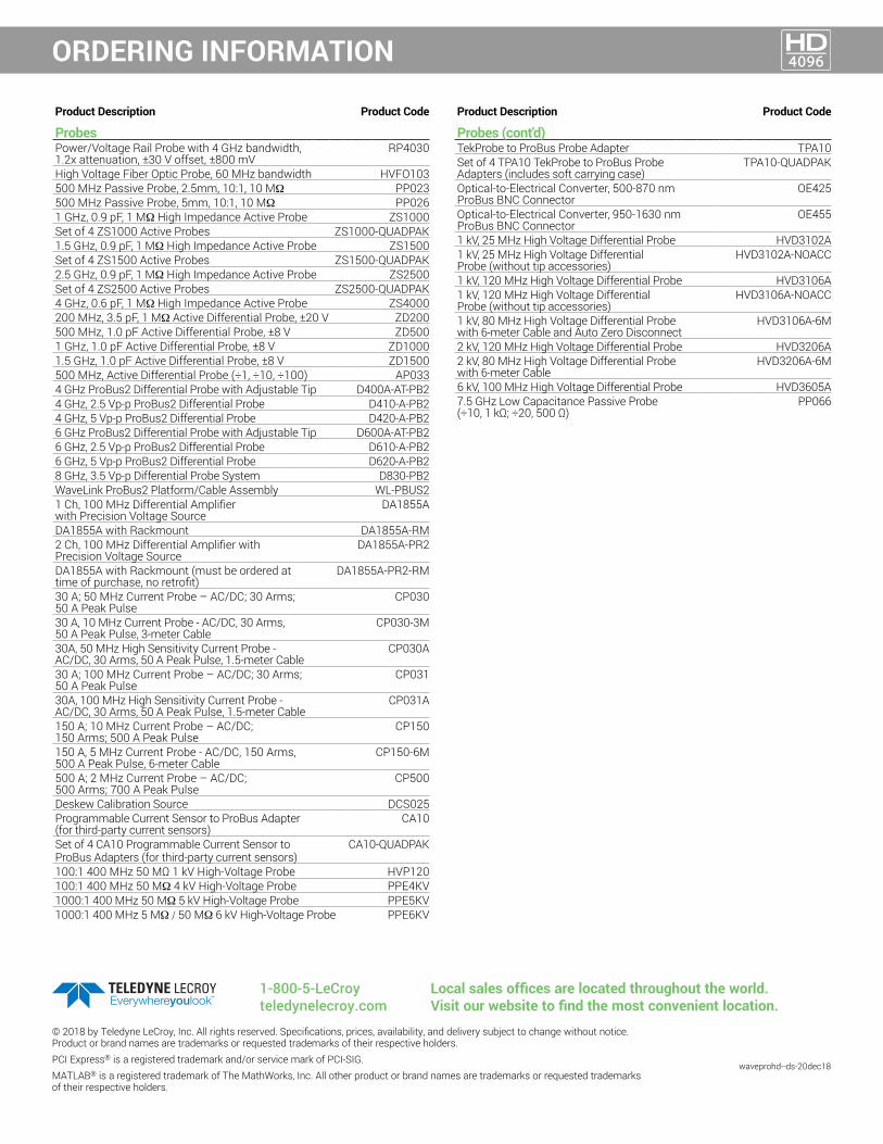
ProbesPower/Voltage Rail Probe with 4 GHz bandwidth, 1.2x attenuation, ±30 V offset, ±800 mV
RP4030
High Voltage Fiber Optic Probe, 60 MHz bandwidth HVFO103500 MHz Passive Probe, 2.5mm, 10:1, 10 MΩ PP023500 MHz Passive Probe, 5mm, 10:1, 10 MΩ PP0261 GHz, 0.9 pF, 1 MΩ High Impedance Active Probe ZS1000Set of 4 ZS1000 Active Probes ZS1000-QUADPAK1.5 GHz, 0.9 pF, 1 MΩ High Impedance Active Probe ZS1500Set of 4 ZS1500 Active Probes ZS1500-QUADPAK2.5 GHz, 0.9 pF, 1 MΩ High Impedance Active Probe ZS2500Set of 4 ZS2500 Active Probes ZS2500-QUADPAK4 GHz, 0.6 pF, 1 MΩ High Impedance Active Probe ZS4000200 MHz, 3.5 pF, 1 MΩ Active Differential Probe, ±20 V ZD200500 MHz, 1.0 pF Active Differential Probe, ±8 V ZD5001 GHz, 1.0 pF Active Differential Probe, ±8 V ZD10001.5 GHz, 1.0 pF Active Differential Probe, ±8 V ZD1500500 MHz, Active Differential Probe (÷1, ÷10, ÷100) AP0334 GHz ProBus2 Differential Probe with Adjustable Tip D400A-AT-PB24 GHz, 2.5 Vp-p ProBus2 Differential Probe D410-A-PB24 GHz, 5 Vp-p ProBus2 Differential Probe D420-A-PB26 GHz ProBus2 Differential Probe with Adjustable Tip D600A-AT-PB26 GHz, 2.5 Vp-p ProBus2 Differential Probe D610-A-PB26 GHz, 5 Vp-p ProBus2 Differential Probe D620-A-PB28 GHz, 3.5 Vp-p Differential Probe System D830-PB2WaveLink ProBus2 Platform/Cable Assembly WL-PBUS21 Ch, 100 MHz Differential Amplifier with Precision Voltage Source
DA1855A
DA1855A with Rackmount DA1855A-RM2 Ch, 100 MHz Differential Amplifier with Precision Voltage Source
DA1855A-PR2
DA1855A with Rackmount (must be ordered at time of purchase, no retrofit)
DA1855A-PR2-RM
30 A; 50 MHz Current Probe – AC/DC; 30 Arms; 50 A Peak Pulse
CP030
30 A, 10 MHz Current Probe - AC/DC, 30 Arms, 50 A Peak Pulse, 3-meter Cable
CP030-3M
30A, 50 MHz High Sensitivity Current Probe - AC/DC, 30 Arms, 50 A Peak Pulse, 1.5-meter Cable
CP030A
30 A; 100 MHz Current Probe – AC/DC; 30 Arms; 50 A Peak Pulse
CP031
30A, 100 MHz High Sensitivity Current Probe - AC/DC, 30 Arms, 50 A Peak Pulse, 1.5-meter Cable
CP031A
150 A; 10 MHz Current Probe – AC/DC; 150 Arms; 500 A Peak Pulse
CP150
150 A, 5 MHz Current Probe - AC/DC, 150 Arms, 500 A Peak Pulse, 6-meter Cable
CP150-6M
500 A; 2 MHz Current Probe – AC/DC; 500 Arms; 700 A Peak Pulse
CP500
Deskew Calibration Source DCS025Programmable Current Sensor to ProBus Adapter (for third-party current sensors)
CA10
Set of 4 CA10 Programmable Current Sensor to ProBus Adapters (for third-party current sensors)
CA10-QUADPAK
100:1 400 MHz 50 MΩ 1 kV High-Voltage Probe HVP120100:1 400 MHz 50 MΩ 4 kV High-Voltage Probe PPE4KV1000:1 400 MHz 50 MΩ 5 kV High-Voltage Probe PPE5KV1000:1 400 MHz 5 MΩ / 50 MΩ 6 kV High-Voltage Probe PPE6KV
Product Description Product Code
Probes (cont'd)TekProbe to ProBus Probe Adapter TPA10Set of 4 TPA10 TekProbe to ProBus Probe Adapters (includes soft carrying case)
TPA10-QUADPAK
Optical-to-Electrical Converter, 500-870 nm ProBus BNC Connector
OE425
Optical-to-Electrical Converter, 950-1630 nm ProBus BNC Connector
OE455
1 kV, 25 MHz High Voltage Differential Probe HVD3102A1 kV, 25 MHz High Voltage Differential Probe (without tip accessories)
HVD3102A-NOACC
1 kV, 120 MHz High Voltage Differential Probe HVD3106A1 kV, 120 MHz High Voltage Differential Probe (without tip accessories)
HVD3106A-NOACC
1 kV, 80 MHz High Voltage Differential Probe with 6-meter Cable and Auto Zero Disconnect
HVD3106A-6M
2 kV, 120 MHz High Voltage Differential Probe HVD3206A2 kV, 80 MHz High Voltage Differential Probe with 6-meter Cable
HVD3206A-6M
6 kV, 100 MHz High Voltage Differential Probe HVD3605A7.5 GHz Low Capacitance Passive Probe(÷10, 1 kΩ; ÷20, 500 Ω)
PP066
© 2018 by Teledyne LeCroy, Inc. All rights reserved. Specifications, prices, availability, and delivery subject to change without notice. Product or brand names are trademarks or requested trademarks of their respective holders. PCI Express® is a registered trademark and/or service mark of PCI-SIG. MATLAB® is a registered trademark of The MathWorks, Inc. All other product or brand names are trademarks or requested trademarks of their respective holders.
waveprohd--ds-20dec18
Local sales offices are located throughout the world. Visit our website to find the most convenient location.
1-800-5-LeCroy teledynelecroy.com