Embed Size (px)
Citation preview

Instruction ManualHigh-Definition Link for Chevrolet(GM)
IW03GF
Model Name IW03GF-HNRAA
Latest Firmware Date 2015 - 06 - 17
Manual Version Rev. 3.5
Language English
Release Date: 2015 - 06 - 19
Car-S
olutio
ns.co
m
www.car-solutions.com [email protected]

• Cautions
• Dimension & Exterior
• Components & Optional parts
• Optional parts for Navigation types
• Full Installation Diagram 「MALIBU」• Full Installation Diagram 「ORLANDO & CRUZE」• Full Installation Diagram 「LACROSSE & CAMARO & VOLT」• HDMI Connection Diagram
• Navigation Connection Diagram(TYPE A & B)
• Navigation Connection Diagram(TYPE C1 & C2)
• Compatibility Chart for Navigation(GPS) box models
• LVDS Connection Diagram
• 20-Pin IN / OUT connector Connection Diagram
• Genuine Rear view camera Connection Diagram
• Hazard Module Connection Diagram
• Body Connector Specifications
• Car Compatibility Chart
• Activation by original buttons of MALIBU
• Activation by original buttons of ORLANDO & CRUZE
• Activation by original buttons of LACROSSE
• Activation by original buttons of CAMARO
• Activation by original buttons of VOLT
• DIP Switch Settings
• Settings
1. Enter into the setting menu
2. HDMI mode settings
3. NAVI mode settings
4. Rear view camera settings
5. AV1(Front view camera) settings
6. Automatic activation function(AV1)
7. AV2 settings
8. System settings
9. System information
10. Information of Dip switch settings
____________________________________________________________ 3
_________________________________________________ 4
_________________________________________ 5
____________________________________ 6
___________________________________ 7
________________________ 8
_____________ 9
__________________________________________ 10
_________________________ 11
______________________ 12
__________________ 13
__________________________________________ 14
______________________ 15
______________________ 16
_________________________________ 17
______________________________________ 18
_____________________________________________ 19
_____________________________ 20
_________________ 21
__________________________ 22
____________________________ 23
________________________________ 24
_________________________________________________ 25
____________________________________ 26
__________________________________________ 27
___________________________________________ 27
____________________________________ 28
_______________________________ 28
____________________________ 29
__________________________________________________ 29
_______________________________________________ 30
___________________________________________ 30
_____________________________ 31
Contents
Car-S
olutio
ns.co
m
www.car-solutions.com [email protected]

3
IW03GF-related
• You should check the names and colors of each wires exactly, before you connect the wires.
ex) CAN HIGH: White wires / CAN LOW: Blue wires
• The ‘POWER / CAN Cable’ should always be connected last and be disconnected first.
• The 'Mode Switch' is an optional part to change modes forcibly without CAN-BUS.
Generally, the CAN-BUS wires are connected for changing modes by original buttons.
• When the reverse gear is not detected by CAN-BUS,
the 'REVERSE 12V IN wire’ should be spliced with 12V power of reverse light.
HDMI device-related
• HDMI mode accepts general-screen resolution of HDMI devices(1080P / 1920*1080).
If screen size of HDMI does not fit on the monitor, should adjust screen size & position in 'settings mode'.
• Generally, '5V 1A Power output(5V USB POWER)' is a standard voltage for charging smartphone.
If you need higher voltage than 5V, you should add a separate power supply.
Navigation(GPS) box-related
• When you connect the power wires(B+, ACC) to the navigation(GPS) box,
the ‘NAVI (12V) OUT' wire supported by IW03GF should be spliced with an ACC wire of navigation box.
• After installation is done, select an applicable navigation(GPS) box model in the 'Navigation model selection
menu' of setting mode.
• The navigation box should be powered off before unplugging the HDMI cable.
Cautions
Car-S
olutio
ns.co
m
www.car-solutions.com [email protected]

4
ⓐ ⓑ ⓒ ⓓ ⓔ
ⓕ ⓖ ⓗ ⓘ ⓙ
Width: 142 mm
Length: 91 mm
Height: 22 mm
Exterior
Dimension
ⓐ DIP SWITCH
ⓑ AV IN / OUT
ⓒ TOUCH IN
ⓓ MODE
ⓔ POWER / CAN
ⓕ HDMI IN
ⓖ 5V USB POWER
ⓗ NAVI IN
ⓘ UART I/F
ⓙ LVDS OUTCar-S
olutio
ns.co
m
www.car-solutions.com [email protected]

5
Power / CAN GVIF IN Cable GVIF PCB HDMI Cable(For GVIF)
AV IN / OUT Cable 5-pin Micro USB Cable
Mode SwitchHDMI Extender(For stick type HDMI device)
HDMI Cable(Male to Male)
GVIF OUT Cable
Components
Optional Parts(sold separately at the indiwork)
Car-S
olutio
ns.co
m
www.car-solutions.com [email protected]

6
iNAVI - CUBE(Type A)
LCD-HDMI Gender
CUBE LCD Cable
MYVI - MS1400 Digital(Type B) Fine Drive - iQ3D7000(Type C)
HDMI CableHDMI Cable
Touch Cable(Connector Type)
50-pin & 4-pin FFC Films
LCD-HDMI Gender
MICROCITY - N-Link(Type B) iNAVI - X1 CUBE(Type B)
Optional parts for Navigation types(sold separately at the indiwork)
Car-S
olutio
ns.co
m
www.car-solutions.com [email protected]

External Rear View
Camera
Audio(AUX) Output of
Navigation Box
Auxiliary(AUX)
Input of the car
External Front View
Camera
AV device
(ex: DTV Box, Divx)
NAVI 12V Power Output(NAVI 12V OUT)
AUDIO-KEY CAN High(White)*Head Unit Controller - 10-pin Connector
Pin # 4 = AUDIO-KEY CAN H(Purple)
Pin # 5 = AUDIO-KEY CAN L(Yellow)
GND Input(GROUND)
B+ Power Input(BAT +)
Touch Cable
for Navigation
HDMI
HDMI
HDMI USB
7
Full Installation Diagram 「MALIBU」
GVIF IN / OUT Connection
*Head Unit - 44-pin Main Connector
Pin # 28 = SINGLE WIRE CAN(Green)
Head Unit(OEM)
AUDIO-KEY CAN Low(Blue)
GVIF
IN / OUT
PCB
HD
MI
1 14
15 28
1 4 5
6 10
SINGLE WIRE CAN(Green)
GVIF IN Cable
GVIF OUT Cable (OEM GVIF Cable)
20-pin IN / OUT Connector(Please refer to page16.)
※ Optional External Devices
RV-CAM Video Input
DIP S/W Setting
12V Power Output & GND Output(RV-CAM Power)
Reverse Signal Detection(optional)
Navigation BoxHDMI Device
FV-CAM Video Input
(AV1)
NAVI Audio Input
Audio Output
AV-Input(AV2)
Mode
Switch
(optional)
HDMI
HDMI USB
USB
Car-S
olutio
ns.co
m
www.car-solutions.com [email protected]
External Rear View
Camera
Audio(AUX) Output of
Navigation Box
Auxiliary(AUX)
Input of the car
External Front View
Camera
AV device
(ex: DTV Box, Divx)
NAVI 12V Power Output(NAVI 12V OUT)
AUDIO-KEY CAN High(White)*Head Unit Controller - 8-pin Connector
Pin # 4 = AUDIO-KEY CAN H(Purple)
Pin # 5 = AUDIO-KEY CAN L(Yellow)
GND Input(GROUND)
B+ Power Input(BAT +)
Touch Cable
for Navigation
HDMI
HDMI
HDMI USB
8
Full Installation Diagram 「ORLANDO & CRUZE」
GVIF IN / OUT Connection
*Head Unit - 44-pin Main Connector
Pin # 14 = SINGLE WIRE CAN(Green)
Head Unit(OEM)
AUDIO-KEY CAN Low(Blue)
GVIF
IN / OUT
PCB
HD
MI
SINGLE WIRE CAN(Green)
GVIF IN Cable
GVIF OUT Cable (OEM GVIF Cable)
20-pin IN / OUT Connector(Please refer to page16.)
※ Optional External Devices
RV-CAM Video Input
DIP S/W Setting
12V Power Output & GND Output(RV-CAM Power)
Reverse Signal Detection(optional)
HDMI Device
FV-CAM Video Input
(AV1)
NAVI Audio Input
Audio Output
AV-Input(AV2)
Mode
Switch
(optional)
1 4
5 8
1 14
15 28
Navigation Box
HDMI
HDMI USB
USB
Car-S
olutio
ns.co
m
www.car-solutions.com [email protected]
External Rear View
Camera
Audio(AUX) Output of
Navigation Box
Auxiliary(AUX)
Input of the car
External Front View
Camera
AV device
(ex: DTV Box, Divx)
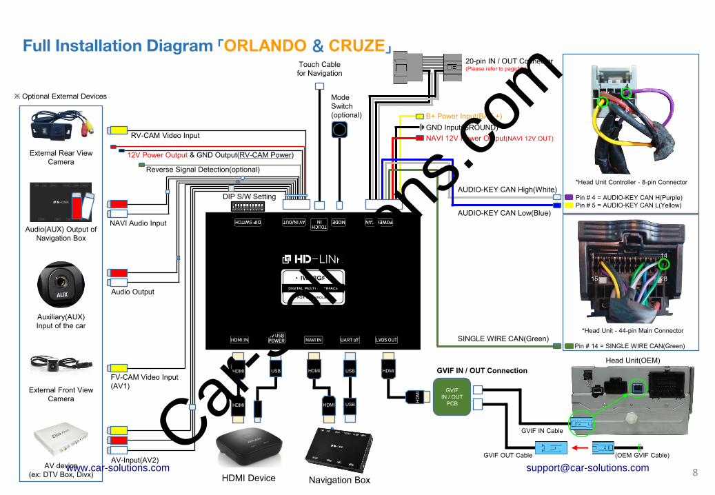
NAVI 12V Power Output(NAVI 12V OUT)
AUDIO-KEY CAN High(White)*Head Unit Controller - 18-pin Connector
Pin # 1 = AUDIO-KEY CAN H(Purple)
" Camaro = (Orange)
Pin # 2 = AUDIO-KEY CAN L(Yellow)
※ Chevrolet Volt(Reversed pin position)
Pin # 1 = AUDIO-KEY CAN L(Yellow)
Pin # 2 = AUDIO-KEY CAN H(Light Blue)
GND Input(GROUND)
B+ Power Input(BAT +)
Touch Cable
for Navigation
HDMI
HDMI
HDMI USB
9
Full Installation Diagram 「LACROSSE & CAMARO & VOLT」
GVIF IN / OUT Connection
*Head Unit - 44-pin Main Connector
Pin # 28 = SINGLE WIRE CAN(Green)
Head Unit(OEM)
AUDIO-KEY CAN Low(Blue)
GVIF
IN / OUT
PCB
HD
MI
SINGLE WIRE CAN(Green)
GVIF IN Cable
GVIF OUT Cable (OEM GVIF Cable)
20-pin IN / OUT Connector(Please refer to page16.)
※ Optional External Devices
RV-CAM Video Input
DIP S/W Setting
12V Power Output & GND Output(RV-CAM Power)
Reverse Signal Detection(optional)
HDMI Device
FV-CAM Video Input
(AV1)
NAVI Audio Input
Audio Output
AV-Input(AV2)
Mode
Switch
(optional)
1 2 9
10 18
1 14
15 28
Navigation Box
HDMI
HDMI USB
USB
AUDIO-KEY CAN Low(Blue)
AUDIO-KEY CAN High(White)
Car-S
olutio
ns.co
m
www.car-solutions.com [email protected]

HDMI
HDMI(Female)
USB
‘Stick Type’ HDMI Devices
HDMI IN 5V USBPOWER
NAVI IN UART I/F LVDS OUT
HDMI Device
HDMI IN 5V USBPOWER
NAVI IN UART I/F LVDS OUT
HDMI Device
USBHDMI
HDMI(Male)
‘Dongle & Adapter’ Type HDMI Devices
HDMI Connection Diagram
(5V-1A Power output for HDMI Device) (5V-1A Power output for HDMI Device)
10
(HDMI Extender) (HDMI Cable)
Car-S
olutio
ns.co
m
www.car-solutions.com [email protected]
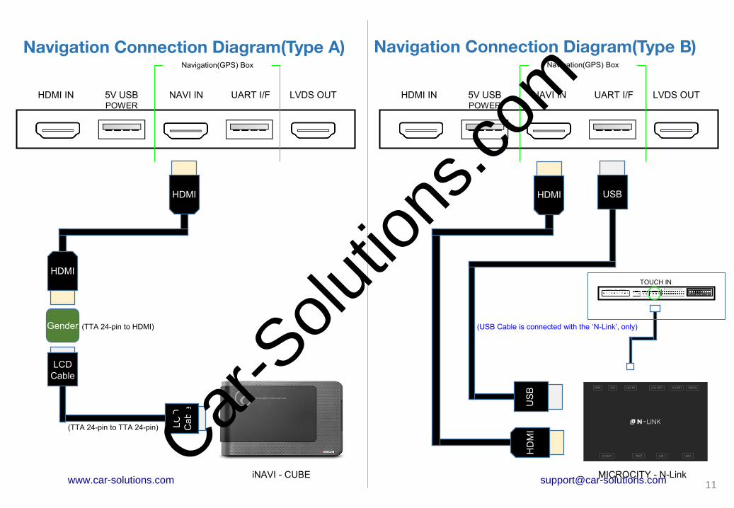
HDMI
HDMI
iNAVI - CUBE
HDMI IN 5V USBPOWER
NAVI IN UART I/F LVDS OUT HDMI IN 5V USBPOWER
NAVI IN UART I/F LVDS OUT
Navigation Connection Diagram(Type A) Navigation Connection Diagram(Type B)
Navigation(GPS) Box Navigation(GPS) Box
Gender
LC
D
Cable
LCD
Cable
(TTA 24-pin to TTA 24-pin)
(TTA 24-pin to HDMI)
11MICROCITY - N-Link
HDMI
HD
MI
USB
US
B
(USB Cable is connected with the ‘N-Link’, only)
TOUCH IN
Car-S
olutio
ns.co
m
www.car-solutions.com [email protected]

HDMI
HDMI IN 5V USBPOWER
NAVI IN UART I/F LVDS OUT HDMI IN 5V USBPOWER
NAVI IN UART I/F LVDS OUT
12
TOUCH IN
HDMI
FINE DRIVE
iQ5000
Touch
IMERCURY
A CLASS PE
Touch
HDMITOUCH IN
HDMI
FINE DRIVE
iQ5000
Touch
IMERCURY
A CLASS PE
Touch
Fine Drive - iQ 3D 5000
(4-p
inF
FC
Film
)
(50-p
inF
FC
Film
)
iMERCURY - Class PE
(4-p
inF
FC
Film
)
(50-p
inF
FC
Film
)
(LCD to HDMI Gender) (LCD to HDMI Gender)
Touch Cable
(Connector Type)
Touch Cable
(Connector Type)
Navigation Connection Diagram(Type C1) Navigation Connection Diagram(Type C2)
Navigation(GPS) Box Navigation(GPS) Box
Car-S
olutio
ns.co
m
www.car-solutions.com [email protected]

Model CountryDip S/W
(Navigation)Required Parts
Installation
Type
iNAVI
CUBESouth Korea
OFF(↑): 1, 2, 3, 4 CUBE LCD Cable LCD-HDMI Gender HDMI Cable
Type A
MICROCITY
N-LinkSouth Korea -
HDMI Cable USB A-A Cable Hazard Module
(Refer to Page.17)
Type B
MYVI
MS1400 DigitalSouth Korea
OFF(↓): 1, 2, 3
ON(↑) : 4HDMI Cable
Type B
iNAVI
X1 CUBESouth Korea
OFF(↑): 1, 2, 3, 4 HDMI Cable
Type B
Fine Drive
iQ 3D 7000South Korea -
50-pin & 4-pin
FFC FilmsTouch Cable
(Connector Type)
LCD-HDMI
Gender
HDMI Cable
Type C
1 2 3 4
ON
↑
13
• The 'IW03GF(HD-Link)' supports navigation(GPS) box models equipped with 'Digital video output'.
• It does not support the 'RGB video signals'.
Compatibility Chart for Navigation(GPS) box models
1 2 3 4
OFF
↓ON
Car-S
olutio
ns.co
m
www.car-solutions.com [email protected]

HDMI
HD
MI
HDMI IN 5V USBPOWER
NAVI IN UART I/F LVDS OUT
GVIF
IN / OUT
PCB
LCD
Cable
(OEM GVIF Cable)
14Monitor(OEM)
Head Unit(OEM)
(Provided GVIF OUT Cable)
(Provided GVIF IN Cable)
GVIF Connection Diagram
GVIF Connection
• 'Genuine(OEM) GVIF Connector' should be connected
to ‘GVIF OUT Connector'.
• ‘Provided GVIF IN Connector' should be connected to
the head unit instead to the genuine connector.
Car-S
olutio
ns.co
m
www.car-solutions.com [email protected]

Head Unit
LCD
Cable
15
POWER / CAN MODE TOUCH-IN AV IN / OUT DIP SWITCH
AU
DIO
-K
EY
CA
N H
AU
DIO
-K
EY
CA
N L
BA
T +
GR
OU
ND
NA
VI 1
2V
OU
T
SW
CA
N
1 2 3 4 5 6 7 8 9 10
(OEM 20-pin Connector)
(20-pin IN Connector)
(20-pin OUT Connector)
RE
AR
CA
M
TO
UC
H IN
TO
UC
H O
UT
20-pin IN / OUT Connector Connection Diagram
Car-S
olutio
ns.co
m
www.car-solutions.com [email protected]

POWER / CAN MODE TOUCH-IN AV IN / OUT DIP SWITCH
AU
DIO
-K
EY
CA
N H
AU
DIO
-K
EY
CA
N L
BA
T +
GR
OU
ND
NA
VI 1
2V
OU
T
SW
CA
N
1 2 3 4 5 6 7 8 9 10 1 2 3 4 5 6 7 8 9 10 11
12 13 14 15 16 17 18 19 20 21 22
GR
OU
ND
IR O
UT
RE
VE
RS
E 1
2V
IN
RE
AR
12V
RE
AR
CA
ME
RA
NA
VI A
UD
IN R
NA
VI A
UD
IN L
AU
DIO
OU
T R
AU
DIO
OU
T L
AV
1 IN
V
AV
2 IN
V
AV
2 IN
R
AV
2 IN
L
(OEM Rear View Camera)
(Connect)
(Connect)
Use the PGS & PDC functions
Dip Switch No.3 ON(▼)
Connect the ‘OEM Rear View Camer(REAR CAM)
RCA connector(Male)’ with the ‘REAR CAMERA
RCA connector(Female) of AV Cable’.
Non-use PGS & PDC funtions
Dip Switch No.3 OFF(▲)
Connect the ‘OEM Rear View Camer(REAR CAM)
RCA connector(Male)’ with the ‘RCA connector
(Female) of 20-pin OUT Connector’.
(20-pin IN
Connector)
(20-pin OUT
Connector)
16
1 5 10
11 15 20
*Head unit - 20-pin connector(Gray)
Pin # 5 = OEM RVC Video+ (Gray/Yellow)
Pin # 15 = Video GND- (White/Blue)
TO
UC
H IN
TO
UC
H O
UT
REAR CAM
Genuine Rear view camera Connection Diagram
Car-S
olutio
ns.co
m
www.car-solutions.com [email protected]

Hazard Module Connection Diagram
POWER / CAN MODE TOUCH-IN AV IN / OUT DIP SWITCH
1 2 3 4 5 6 7 8 9 10 11
12 13 14 15 16 17 18 19 20 21 22
GR
OU
ND
IR O
UT
RE
VE
RS
E 1
2V
IN
RE
AR
12V
RE
AR
CA
ME
RA
NA
VI A
UD
IN R
NA
VI A
UD
IN L
AU
DIO
OU
T R
AU
DIO
OU
T L
AV
1 IN
V
AV
2 IN
V
AV
2 IN
R
AV
2 IN
L
Malibu - Hazard Connector
Pin #10 = Hazard(-) (Green/White)
1 6
7 10 12
17
GNDIR IN
(20 cm)
Orlando - Hazard Connector
Pin #4 = Hazard(-) (Green/White)
1 2 3 4
*Hazard Module is just available with ‘Smart Drive function of N-Link’ navigation in South Korea.
Old Version Module
Hazard
Lig
ht
GN
D
IR I
N
New Version Module
Ben
z H
azard
Lig
ht
(For IW04-MB14)
BM
W/A
UD
I H
azard
Lig
ht
Hazard
Module
(4-Pin)
Hazard
Module
(3-Pin)
(100 cm)Car-S
olutio
ns.co
m
www.car-solutions.com [email protected]

POWER / CAN MODE TOUCH-IN AV IN / OUT DIP SWITCH
1 2 3 4 5 6 7 8 9 10 11
12 13 14 15 16 17 18 19 20 21 22
1 BATTERY POWER INPUT
2 GND INPUT
3 NAVI 12V POWER OUTPUT
4 SINGLE WIRE CAN
5 AUDIO-KEY CAN HIGH
6 AUDIO-KEY CAN LOW
7
20-PIN IN / OUT CONNECTOR8
9
10
AU
DIO
-K
EY
CA
N H
AU
DIO
-K
EY
CA
N H
BA
T +
GR
OU
ND
NA
VI 1
2V
OU
T
SW
CA
N
1 RV-CAM VIDEO INPUT 12 GND(RV-CAM VIDEO)
2 RV-CAM POWER OUT 13 GND OUTPUT(RV-CAM)
3 REVERSE DETECTION 14 IR OUT
4 NAVI AUX INPUT R 15 GND(NAVI AUX IN R)
5 NAVI AUX INPUT L 16 GND(NAVI AUX IN L)
6 AUDIO OUTPUT R 17 GND(AUDIO OUT R)
7 AUDIO OUTPUT L 18 GND(AUDIO OUT L)
8 AV1 VIDEO INPUT 19 GND(AV1 VIDEO IN)
9 AV2 VIDEO INPUT 20 GND(AV2 VIDEO IN)
10 AV2 AUDIO INPUT R 21 GND(AV2 AUDIO IN R)
11 AV2 AUDIO INPUT L 22 GND(AV2 AUDIO IN L)
GR
OU
ND
IR O
UT
RE
VE
RS
E 1
2V
IN
RE
AR
12V
RE
AR
CA
ME
RA
NA
VI A
UD
IN R
NA
VI A
UD
IN L
1 2 3 4
AU
DIO
OU
T R
AU
DIO
OU
T L
AV
1 IN
V
AV
2 IN
V
AV
2 IN
R
AV
2 IN
L
Mode Switch
Touch Cable
(Connector Type)
1 2
18
Length: 100 cm Length: 20 cm
Length: 150 cm Length: 100 cm
1 2 3 4
4 3 2 1
Length: 40 cm
Touch Cable
(Film Type)
TO
UC
H IN
TO
UC
H O
UT
1 2 3 4 5 6 7 8 9 10
Body Connector specifications
• The colors of each wires can be changed under manufacturer’s circumstance.
Car-S
olutio
ns.co
m
www.car-solutions.com [email protected]

Car ModelsProduction
YearSpecific Models
Malibu
(Chevrolet)2012 -
Equipped with MyLink, New MyLink
or OEM NAVI system
Orlando
(Chevrolet)2013 -
Equipped with New MyLink
or OEM NAVI system
Lacrosse
(Buick)2010 -
Equipped with Intellilink(Next Gen Info.)
or OEM NAVI system
Camaro
(Chevrolet)2013 -
Equipped with New MyLink
or OEM NAVI system
Cruze
(Chevrolet)2013 - Equipped with OEM NAVI system
Volt
(Chevrolet)2013 - Equipped with MyLink
The IW03GF is used in combination with
Chevrolet(GM) INFOTAINMENT system.
- Malibu <New MyLink, OEM NAVI>
- Orlando <New MyLink, OEM NAVI>
- Lacrosse <Intellilink, OEM NAVI>
- Camaro <New MyLink, OEM NAVI>
- Cruze <OEM NAVI>
- Volt <MyLink>
The IW03GF supports the
Chevrolet(GM) original screen &
Head unit equipped with ‘GVIF
connector’ only.
Please check the specification of
original GVIF connector on the
sidelines of a production year.
19
Car Compatibility Chart
Car-S
olutio
ns.co
m
www.car-solutions.com [email protected]
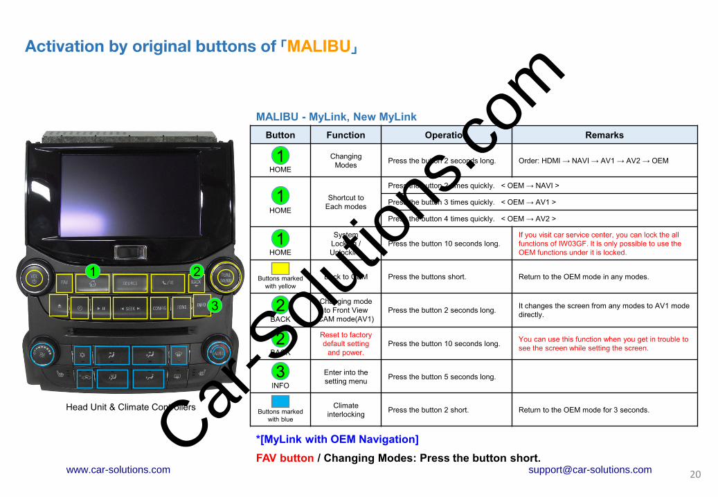
Activation by original buttons of 「MALIBU」
1
Button Function Operation Remarks
HOME
Changing
ModesPress the button 2 seconds long. Order: HDMI → NAVI → AV1 → AV2 → OEM
HOME
Shortcut to
Each modes
Press the button 2 times quickly. < OEM → NAVI >
Press the button 3 times quickly. < OEM → AV1 >
Press the button 4 times quickly. < OEM → AV2 >
HOME
System
Locking /
Unlocking
Press the button 10 seconds long.
If you visit car service center, you can lock the all
functions of IW03GF. It is only possible to use the
OEM functions under it is locked.
Buttons marked
with yellow
Back to OEM Press the buttons short. Return to the OEM mode in any modes.
BACK
Changing mode
to Front View
CAM mode(AV1)
Press the button 2 seconds long.It changes the screen from any modes to AV1 mode
directly.
BACK
Reset to factory
default setting
and power.
Press the button 10 seconds long.You can use this function when you get in trouble to
see the screen while setting the screen.
INFO
Enter into the
setting menu Press the button 5 seconds long.
Buttons marked
with blue
Climate
interlockingPress the button 2 short. Return to the OEM mode for 3 seconds.
1
1
MALIBU - MyLink, New MyLink
2
20
2
Head Unit & Climate Controllers
3
1 2
3
*[MyLink with OEM Navigation]
FAV button / Changing Modes: Press the button short.Car-S
olutio
ns.co
m
www.car-solutions.com [email protected]

Activation by original buttons of 「ORLANDO」
ORLANDO - New MyLink
21
Head Unit & Climate Controllers
1
2
3 1
Button Function Operation Remarks
HOME
Changing
ModesPress the button 2 seconds long. Order: HDMI → NAVI → AV1 → AV2 → OEM
HOME
Shortcut to
Each modes
Press the button 2 times quickly. < OEM → NAVI >
Press the button 3 times quickly. < OEM → AV1 >
Press the button 4 times quickly. < OEM → AV2 >
HOME
System
Locking /
Unlocking
Press the button 10 seconds long.
If you visit car service center, you can lock the all
functions of IW03GF. It is only possible to use the
OEM functions under it is locked.
Buttons marked
with yellow
Back to OEM Press the buttons short. Return to the OEM mode in any modes.
BACK
Changing mode
to Front View
CAM mode(AV1)
Press the button 2 seconds long.It changes the screen from any modes to AV1 mode
directly.
BACK
Reset to factory
default setting
and power.
Press the button 10 seconds long.You can use this function when you get in trouble to
see the screen while setting the screen.
INFO
Enter into the
setting menu Press the button 5 seconds long.
Buttons marked
with blue
Climate
interlockingPress the button 2 short. Return to the OEM mode for 3 seconds.
1
1
2
2
3
*[MyLink with OEM Navigation]
NAVI button / Changing Modes: Press the button short.Car-S
olutio
ns.co
m
www.car-solutions.com [email protected]

Activation by original buttons of 「LACROSSE」
Lacrosse – Intellilink Infotainment
22
Head Unit & Climate Controllers
*[Intellilink with OEM Navigation]
NAVI button / Changing Modes: Press the button short.
1
2
3
1
Button Function Operation Remarks
HOME
Changing
ModesPress the button 2 seconds long. Order: HDMI → NAVI → AV1 → AV2 → OEM
HOME
Shortcut to
Each modes
Press the button 2 times quickly. < OEM → NAVI >
Press the button 3 times quickly. < OEM → AV1 >
Press the button 4 times quickly. < OEM → AV2 >
HOME
System
Locking /
Unlocking
Press the button 10 seconds long.
If you visit car service center, you can lock the all
functions of IW03GF. It is only possible to use the
OEM functions under it is locked.
Buttons marked
with yellow
Back to OEM Press the buttons short. Return to the OEM mode in any modes.
BACK
Changing mode
to Front View
CAM mode(AV1)
Press the button 2 seconds long.It changes the screen from any modes to AV1 mode
directly.
BACK
Reset to factory
default setting
and power.
Press the button 10 seconds long.You can use this function when you get in trouble to
see the screen while setting the screen.
INFO
Enter into the
setting menu Press the button 5 seconds long.
Buttons marked
with blue
Climate
interlockingPress the button 2 short. Return to the OEM mode for 3 seconds.
1
1
2
2
3
Car-S
olutio
ns.co
m
www.car-solutions.com [email protected]

Activation by original buttons of 「CAMARO」
Head Unit & Climate Controllers
1
Button Function Operation Remarks
BACK
Changing
ModesPress the button 2 seconds long. Order: HDMI → NAVI → AV1 → AV2 → OEM
BACK
Shortcut to
Each modes
Press the button 2 times quickly. < OEM → NAVI >
Press the button 3 times quickly. < OEM → AV1 >
Press the button 4 times quickly. < OEM → AV2 >
BACK
System
Locking /
Unlocking
Press the button 10 seconds long.
If you visit car service center, you can lock the all
functions of IW03GF. It is only possible to use the
OEM functions under it is locked.
Buttons marked
with yellow
Back to OEM Press the buttons short. Return to the OEM mode in any modes.
TONE
Changing mode
to Front View
CAM mode(AV1)
Press the button 2 seconds long.It changes the screen from any modes to AV1 mode
directly.
TONE
Reset to factory
default setting
and power.
Press the button 10 seconds long.You can use this function when you get in trouble to
see the screen while setting the screen.
CONFIG
Enter into the
setting menu Press the button 5 seconds long.
Buttons marked
with blue
Climate
interlockingPress the button 2 short. Return to the OEM mode for 3 seconds.
CAMARO - New MyLink
1
2
3
2
*[MyLink with OEM Navigation]
MENU/SELECT button / Switching to AV1 mode: Press ‘2 seconds’ / Factory Reset: ‘10 seconds’ long.
SOURCE button / Entering into the setting menu: Press the button 5 seconds long.
2
3
3
23
1
1
2
2
3
Car-S
olutio
ns.co
m
www.car-solutions.com [email protected]

Activation by original buttons of 「VOLT」
1
Button Function Operation Remarks
HOME
Changing
ModesPress the button 2 seconds long. Order: HDMI → NAVI → AV1 → AV2 → OEM
HOME
Shortcut to
Each modes
Press the button 2 times quickly. < OEM → NAVI >
Press the button 3 times quickly. < OEM → AV1 >
Press the button 4 times quickly. < OEM → AV2 >
HOME
System
Locking /
Unlocking
Press the button 10 seconds long.
If you visit car service center, you can lock the all
functions of IW03GF. It is only possible to use the
OEM functions under it is locked.
BACK
Changing mode
to Front View
CAM mode(AV1)
Press the button 2 seconds long.It changes the screen from any modes to AV1 mode
directly.
BACK
Reset to factory
default setting
and power.
Press the button 10 seconds long.You can use this function when you get in trouble to
see the screen while setting the screen.
INFO
Enter into the
setting menu Press the button 5 seconds long.
1
1
VOLT - MyLink
2
24
2
Head Unit & Climate Controllers
3
1
2
3
Car-S
olutio
ns.co
m
www.car-solutions.com [email protected]

Pin
No.ON(▼) OFF(▲)
1 HDMI Mode Skip HDMI Mode
2 Navigation Mode Skip Navigation Mode
3 External Rear View Camera Original Rear View Camera
4External Front View
Camera(AV1 Mode)
Skip External Front View
Camera(AV1 Mode)
5 AV2 Mode Skip AV2 Mode
6
Selection of car model
7
8
9
10
25
OFF
ON
ON: ▼ OFF:▲
No.6 No.7 No.8 No.9 No.10 Car Models
OFF(▲) OFF(▲) OFF(▲) OFF(▲) OFF(▲)Malibu <MyLink, New MyLink>
Volt <MyLink>
OFF(▲) OFF(▲) ON(▼) ON(▼) OFF(▲) Malibu <OEM Navigation>
OFF(▲) OFF(▲) OFF(▲) OFF(▲) ON(▼) Orlando <New MyLink>
OFF(▲) OFF(▲) ON(▼) OFF(▲) ON(▼) Orlando 2015 <New MyLink>
*After August 2014
OFF(▲) OFF(▲) OFF(▲) ON(▼) ON(▼) Lacrosse <Intellilink>
OFF(▲) OFF(▲) OFF(▲) ON(▼) OFF(▲) Lacrosse <OEM Navigation>
OFF(▲) OFF(▲) ON(▼) OFF(▲) OFF(▲) Camaro <MyLink, OEM Navi>
OFF(▲) OFF(▲) ON(▼) ON(▼) ON(▼)Orlando <OEM Navigation>
Cruze <OEM Navigation>
OFF(▲) OFF(▲) ON(▼) ON(▼) ON(▼)Malibu 2013 인포팩(iQ7000Black화면값조정)
DIP Switch Settings
Car-S
olutio
ns.co
m
www.car-solutions.com [email protected]

Button Function Operation
INFO(Head Unit Controller)
Enter into the
setting menu
Press the ‘INFO’ button
5 seconds long.
Touch Screen(OEM Monitor)
All functions of setting menu of IW03GF is controlled
by a touch screen of the OEM monitor.
26
Settings
1. Enter into the setting menu.
<Press the ‘INFO’ button 5 seconds long. / Camaro: CONFIG button>
- HDMI & Navigation settings
- Rear view camera settings
- AV-input settings
- System settings
- System informationCar-S
olutio
ns.co
m
www.car-solutions.com [email protected]

27
Settings
2. HDMI mode settings
- Mode selection: HDMI ↔ NAVI
- Image display= Adjust the values of brightness and contrast
Red-Green-Blue colors of HDMI display.
- Screen position & size= Adjust position and size of HDMI display.
3. NAVI mode settings
- Mode selection: NAVI ↔ HDMI
- Image display= Adjust the values of brightness and contrast
Red-Green-Blue colors of NAVI display.
- Screen position & size= Adjust position and size of NAVI display.
- Navigation model selection① Default(N-Link) ② iNAVI - CUBE ③ Class settop
④ MYVI - MS1400 ⑤ iQ 3D 7000 ⑥ Class PE
Car-S
olutio
ns.co
m
www.car-solutions.com [email protected]

28
Settings
4. Rear view camera settings
- Parking guide lines= Adjust position of parking guide lines and
select the lines ‘ON or OFF’.
- Parking distance control= Select the PDC ‘ON or OFF’.
- Image display= Adjust the values of brightness and contrast
Red-Green-Blue colors of Rear view camera display.
5. AV1(Front view camera) settings
- Mode selection: AV1(Front view camera) ↔ AV2
- Image display= Adjust the values of brightness and contrast
Red-Green-Blue colors of AV1(Front view camera) display.
- Screen position & size= Adjust the position and size of AV1 display.
- Automatic activation function(AV1)= * Please refer to next page.
- Parking distance control= Entry Disabled / Not applicable.
Car-S
olutio
ns.co
m
www.car-solutions.com [email protected]

29
Settings
6. Automatic activation function(AV1)
- Shift gear from reverse to drive
- Shift gear from parking to drive
* When you shift gear ‘from reverse to drive’ or ‘from parking to drive’,
it just works automatically during the activation time you selected.
7. AV2 settings
- Mode selection: AV2 ↔ AV1(Front view camera)
- Image display= Adjust the values of brightness and contrast
Red-Green-Blue colors of AV2 display.
- Screen position & size= Adjust the position and size of AV2 display.
Car-S
olutio
ns.co
m
www.car-solutions.com [email protected]

30
Settings
8. System settings
- Safe mode= Select the one of two between ‘ON and OFF’.
* If you select ‘ON’, 3 modes(HDMI, NAVI and AV2) will be faded out
when the car is driven.
- Factory default= Reset all setting values to factory default setting.
9. System information
- Mode name: IW03GF-HNRAA
- Firmware date: 2015 - 06 - 17(Latest firmware date)
- = You can check the current firmware version date.
- Dip switch settings= You can check the current positions of dip switch settings.
Car-S
olutio
ns.co
m
www.car-solutions.com [email protected]

Settings
10. Information of Dip switch settings
* You can check the current positions of dip switch settings.
31
ex 2)
Actual DIP switch values. (→)
Appears on the setting menu. (↓)
ex 1)
Actual DIP switch values. (→)
Appears on the setting menu. (↓)
Car-S
olutio
ns.co
m
www.car-solutions.com [email protected]