Embed Size (px)
Citation preview

ii
ABSTRACT
In the light of the increasing terrorist SAMs threat to civil and military aircraft, the
need of a high-fidelity, low-cost, IR signature scene modelling and simulation
capability that could be used for development, testing and evaluation of IRCM
systems cannot be overlooked.
The performance evaluation, training and testing of IR missiles or other IR based
weapon systems, is very expensive and is also dependent upon atmospheric factors.
Whereas, the computer based non-destructive simulation can provide a cost-effective
alternative to field trials.
An effort has been made to model the IR scene signature using virtual reality
modelling tools and integrating this model into the missile-target engagement and
countermeasure simulator. The developed algorithm can simulate passive IR imaging
seeker engagements with aerial targets. The presented algorithm uses the developed
models for IR signature of the target, the background, the flare spectral and temporal
responses and the flare ballistic trajectory. The missile guidance, auto-pilot and
tracker algorithms have also been developed. The atmospheric conditions have been
modelled, using LOWTRAN, as “good”, “typical” or “bad” to account for
atmospheric transmittance and the sky-radiance. The results were analysed and
validated through four test scenarios. The code is written in MATLAB which gives it
openness for user verification/validation and also flexibility for any future
modifications.
The work presented may help the IRCM designer and pilots to evaluate potential
strategies to defeat the imaging seeker threat.

iii
DEDICATION
Specially dedicated with love and prayers to my mother who is suffering from
“Pulmonary Fibrosis” disease.
Secondly, dedicated to my father, sisters and brother who have always prayed and
guided me throughout my life.
Finally, dedicated to my gorgeous wife and lovely children for their patience and
support during my PhD.

iv
ACKNOWLEDGEMENTS
I was able to accomplish this immense task mainly because of the whole hearted
support, valuable guidance, professional critic and moral support extended to me by
Dr. Mark A. Richardson, who has supervised this research, leading to PhD thesis, in a
very friendly and encouraging atmosphere. I am extremely thankful to Dr Mark for all
his support and the time he devoted for in depth review of my thesis.
Many of the ideas explored in this research were contributed by individuals who gave
their time and supported me at different stages of this work. In particular, I would like
to thank Professor Richard Ormondroyd, Dr. Martin L. Fair of DSTL (UK), Dr Evan
Hughes, Dr. Robin Jenkin, Dr. John Coath, Mr. Roy Walmsley of Chemring
Countermeasures, High Post, UK and Dr. Peter Silson.
I would like to thank my departmental staff for their support. Also, I would like to
thank fellow research students at Post Graduated Centre for staying long hours
together and sharing ideas.
Finally, I would like to thank the NUST, Pakistan for sponsoring me and Pakistan Air
Force for sparing me for this research work.

v
TABLE OF CONTENTS
ABSTRACT..................................................................................................................ii
DEDICATION............................................................................................................ iii
ACKNOWLEDGEMENTS .......................................................................................iv
TABLE OF CONTENTS ............................................................................................v
LIST OF TABLES .....................................................................................................xv
LIST OF FIGURES .................................................................................................xvii
ACRONYMS .......................................................................................................... xxiii
1 INTRODUCTION................................................................................................1
1.1 Background ....................................................................................................1
1.2 Aim ................................................................................................................1
1.3 Objectives ......................................................................................................1
1.4 Need of IR Signature Modelling and Simulation ..........................................2
1.5 Why Commercial Off-the-Shelf?...................................................................2
1.6 Future Utility..................................................................................................3
1.7 Summary........................................................................................................3
2 IR Radiations and Signature ..............................................................................5
2.1 Introduction....................................................................................................5
2.2 Infrared Radiations.........................................................................................6
2.2.1 Plank’s Law for Blackbody Radiations .................................................6
2.2.2 Radiant Properties of Materials .............................................................7
2.2.3 Emissivity ..............................................................................................8
2.2.4 Spectral Radiance...................................................................................8
2.2.5 Power .....................................................................................................9
2.2.6 Solid Angle ..........................................................................................10
2.2.7 Projected Area......................................................................................11
2.3 Sources of Radiation ....................................................................................11
2.3.1 Sources of Radiation on Jet Aircraft ....................................................12
2.3.2 Sources of Radiation on Ground Vehicles...........................................14
2.4 Transmission of Infrared Radiation through Earth’s Atmosphere...............15
2.4.1 Atmospheric Transmittance Calculation Software ..............................15
2.4.2 Atmospheric Transmittance .................................................................17

vi
2.4.3 Atmospheric Path-radiance..................................................................18
2.5 IR Signature Scene Model Ingredients ........................................................19
2.5.1 Targets..................................................................................................19
2.5.2 Background as Clutter or Source .........................................................20
2.5.3 Thermally Static IR Background .........................................................20
2.6 Low and High-Fidelity IR Signature Models ..............................................21
2.7 Conclusion ...................................................................................................21
3 IR Guided Missiles .............................................................................................23
3.1 Introduction..................................................................................................23
3.2 Evolution of Heat Seeking Missiles.............................................................23
3.2.1 First Generation Seekers ......................................................................23
3.2.2 Second Generation Seekers..................................................................26
3.2.3 Third Generation Seekers ....................................................................29
3.2.4 Fourth Generation Seekers...................................................................31
3.3 Missile Tracking Techniques.......................................................................33
3.3.1 Gated Video Tracker............................................................................33
3.3.2 Correlation Tracker ..............................................................................34
3.4 Missile Guidance .........................................................................................35
3.4.1 Line-of-Sight Guidance .......................................................................35
3.4.2 Homing Guidance ................................................................................36
3.4.3 Navigational Guidance.........................................................................36
3.4.4 Compound Guidance ...........................................................................36
3.4.5 Guided Missile Trajectories.................................................................37
3.4.6 Proportional Navigation Guidance ......................................................40
3.4.7 Pursuit Course Guidance......................................................................42
3.5 Missile Controls ...........................................................................................43
3.6 Missile Aerodynamics .................................................................................44
3.6.1 Aerodynamics Drag .............................................................................44
3.6.2 Lateral Acceleration of the Missile......................................................45
3.7 Missile Fuses................................................................................................46
3.8 Summary......................................................................................................46
3.9 Conclusion ...................................................................................................47
4 Infrared countermeasures.................................................................................49

vii
4.1 Introduction..................................................................................................49
4.2 Defence against Heat Seeking Missiles .......................................................49
4.2.1 Pre-Launch Defence.............................................................................49
4.2.2 Post Launch Defence ...........................................................................49
4.3 Infrared Signature Suppression....................................................................50
4.3.1 Suppressing Heat Source .....................................................................51
4.3.2 Reducing Emissivity ............................................................................51
4.4 Infrared Countermeasures............................................................................51
4.5 Off-board IRCM Flares................................................................................52
4.5.1 Conventional Flares .............................................................................53
4.5.2 Multi-spectral Flares ............................................................................53
4.5.3 Special Material Decoy........................................................................54
4.5.4 Electronically Configurable IR Towed Decoy ....................................55
4.5.5 Kinematics or Fly-along Flares............................................................55
4.5.6 Flare Performance Factors ...................................................................55
4.5.7 Flare Limitations..................................................................................58
4.5.8 Flight Guard Self Protection System ...................................................58
4.5.9 Wide-body Integrated Platform Protection System .............................58
4.5.10 Comet IRCM Pod ................................................................................58
4.6 Active IR Countermeasures .........................................................................59
4.6.1 Advanced Threat Infrared Countermeasures .......................................59
4.6.2 Directional IRCM ................................................................................60
4.6.3 Large Aircraft Infrared Countermeasures ............................................60
4.6.4 Tactical Aircraft Directional IRCM.....................................................61
4.6.5 Closed-loop IR Countermeasures ........................................................61
4.6.6 Mobile Tactical High-energy Laser .....................................................61
4.7 Missile Approach Warning System .............................................................62
4.8 IR Counter-countermeasures against IRCM Flares .....................................63
4.9 Improvements in Flares Design ...................................................................64
4.10 Terrorist Missile Threat to Commercial Airlines.........................................64
4.11 IRSS and IRCM System Analysis and Evaluation Software.......................66
4.11.1 DSTL Fly-in 2000 Model ....................................................................66
4.11.2 Tactical Engagement Simulation Software..........................................67
viii
4.11.3 Chemring Countermeasures CounterSim ............................................67
4.12 Summary......................................................................................................68
4.13 Conclusion ...................................................................................................69
5 Simulation and Modelling .................................................................................71
5.1 Introduction..................................................................................................71
5.2 Simulation and Modelling............................................................................71
5.2.1 Types of Simulation.............................................................................71
5.2.2 Uses of Simulation and Modelling ......................................................72
5.2.3 Application of Modelling and Simulation in Military Systems...........73
5.2.4 Low cost PC Based Systems................................................................74
5.2.5 Military Simulators Developed around COTS Software .....................74
5.2.6 Commercial Modelling Tools ..............................................................76
5.3 Computer Graphics Hardware .....................................................................76
5.3.1 Applications of Hardware Graphics.....................................................76
5.3.2 Advantages of Hardware Graphics ......................................................77
5.3.3 Computer Graphics Card .....................................................................77
5.3.4 Integrated Graphics Processor .............................................................79
5.3.5 Graphics Hardware Manufacturers ......................................................80
5.3.6 AGP and PCI Express..........................................................................80
5.3.7 Nvidia® SLI Technology .....................................................................81
5.4 Graphics APIs ..............................................................................................81
5.4.1 OpenGL® .............................................................................................81
5.4.2 Architecture Review Board..................................................................82
5.4.3 Difference between Direct3D and OpenGL ........................................82
5.5 Realism ........................................................................................................83
5.5.1 Physical Realism..................................................................................83
5.5.2 Photo Realism ......................................................................................83
5.5.3 Functional Realism ..............................................................................84
5.6 Computer Graphics Rendering ....................................................................84
5.6.1 Rendering Pipeline Stages ...................................................................84
5.6.2 Types of Rendering..............................................................................85
5.6.3 Illumination Techniques ......................................................................87
5.7 Virtual Reality Modelling Language ...........................................................87

ix
5.7.1 Military Vehicles 3D Virtual Reality Models......................................88
5.7.2 Open InventorTM vs VRML .................................................................89
5.8 Virtual Reality Toolbox ...............................................................................89
5.8.1 V-Realm™ Builder/Editor...................................................................90
5.8.2 Virtual Reality Viewer.........................................................................90
5.8.3 MATLAB VRML Interface.................................................................90
5.9 MATLAB® Aerospace Blockset..................................................................91
5.10 Microsoft Flight Simulator ..........................................................................91
5.11 Unmanned Dynamics AeroSim Blockset ....................................................92
5.12 FlightGear Flight Simulator.........................................................................92
5.13 Conclusion ...................................................................................................93
6 Development of an IR Signature Model...........................................................95
6.1 Introduction..................................................................................................95
6.2 IR Signature Modelling of the Background.................................................95
6.2.1 Background Input Parameters..............................................................95
6.2.2 Sky-radiance Data Sets ........................................................................96
6.2.3 Calculating Background Radiance.......................................................98
6.2.4 Multiple Backgrounds or Sub-backgrounds ........................................99
6.3 IR Signature Modelling of the Targets ......................................................100
6.3.1 Target Input Parameters .....................................................................100
6.3.2 Calculating Radiance of the Target....................................................101
6.3.3 More Realistic Targets with Different Temperature Zones...............102
6.3.4 Adding Reflection Effects to the Model ............................................103
6.3.5 Modelling IR Signature of the Exhaust Gas Plume ...........................105
6.4 IR Signature Modelling of IRCM (Flares).................................................109
6.4.1 Input Data Required for Flare IR Signature Modelling .....................109
6.4.2 Assumptions for Modelling Flare IR Signature.................................110
6.4.3 Modelling IR Spectral Response of Flare..........................................110
6.4.4 Modelling Temporal Response of IR Flare .......................................111
6.5 Modelling Atmospheric Effects on IR Signature.......................................113
6.5.1 Inputs Required to Generate Atmospheric Transmission Data..........114
6.5.2 Transmittance to Atmospheric Attenuation Coefficient Conversion.115
6.5.3 Wave-numbers to Micrometers Conversion ......................................116

x
6.5.4 Calculating Atmospheric Transmittance for each Target ..................117
6.5.5 Scattering Effects of the Atmosphere ................................................117
6.5.6 Modelling Atmospheric Path-radiance ..............................................118
6.6 Modelling Missile IR Detector and Optics ................................................119
6.6.1 Missile Input Parameters....................................................................119
6.7 Calculating Power Received at the Detector .............................................120
6.7.1 Calculating Projected Area of the Detector .......................................121
6.7.2 Calculating Solid-angle of Seeker Optics ..........................................121
6.7.3 Exposed Area of Targets as Projected on Background......................122
6.7.4 Point Source or Extended Source Target ...........................................123
6.7.5 Background Area ...............................................................................123
6.7.6 Power received at the Detector Due to Target and Background........124
6.7.7 Lock-on Range or Maximum Range Prediction ................................126
6.7.8 Fidelity of the Model .........................................................................126
6.8 Data Stored in Excel Spreadsheets ............................................................127
6.9 Source Code of the Main Algorithm..........................................................128
6.10 Conclusion .................................................................................................128
7 Modelling the IR Scene in a 3D Virtual World .............................................131
7.1 Introduction................................................................................................131
7.2 Why VRML ...............................................................................................131
7.3 Developing the 3D Virtual World..............................................................131
7.4 Military Targets 3D VRML Models ..........................................................132
7.4.1 F-16 Fighting Falcon 3D VRML Model............................................132
7.4.2 C-130 Hercules 3D VRML Model ....................................................133
7.4.3 T-62 Tank 3D VRML Model.............................................................135
7.4.4 Boeing B-737 3D VRML Model .......................................................136
7.4.5 Helicopter 3D VRML Model.............................................................137
7.5 Altering Target VRML Model for IR Signature Modelling ......................137
7.5.1 Grouping Parts as Sub-targets............................................................138
7.5.2 Modelling Appearance of Sub-targets ...............................................139
7.5.3 Controlling the Translation and Rotation fields of the Target ...........145
7.5.4 Adding Leading-edge Geometry........................................................146
7.5.5 Adding Exhaust Gas Plume Geometry ..............................................147

xi
7.6 Modelling IR Background .........................................................................148
7.7 Modelling IR Atmosphere as “Fog” in VRML..........................................150
7.8 Modelling Multiple Viewpoints.................................................................151
7.9 Modelling Missile Optics and Seeker-head ...............................................152
7.9.1 Missile Optics Field-of-View ............................................................153
7.9.2 FOV to Focal Length Conversion......................................................155
7.9.3 Modelling “NavigationInfo” Node for Missile Seeker View ............155
7.10 Modelling IR Flare Geometry and Aerodynamics.....................................157
7.10.1 Inputs for Flare Modelling .................................................................157
7.10.2 Assumptions for Flare Modelling ......................................................158
7.10.3 Modelling Flare Pallet Geometry.......................................................159
7.10.4 Modelling Flare IR Plume 3D Geometry...........................................160
7.10.5 Modelling Flare Dispenser.................................................................162
7.10.6 Modelling Flare Plume Appearance ..................................................164
7.10.7 Modelling Flare Trajectory in 3D ......................................................165
7.11 VRML vs IR Comparrision Summary.......................................................172
7.12 Conclusion .................................................................................................174
8 Target Manoeuvrability and Missile Guidance and Control Modelling ....175
8.1 Introduction................................................................................................175
8.2 VR World Fields for Target and Missile Movement .................................175
8.3 Assumptions for Missile and Target Movement........................................177
8.3.1 Target Degree-of-freedom .................................................................177
8.3.2 Missile Degree-of-freedom................................................................178
8.3.3 Targets Initial Position.......................................................................178
8.3.4 Information about Missile Launch.....................................................178
8.4 User Inputs and Typical Data Ranges........................................................179
8.5 An Aircraft in a Level Turn .......................................................................180
8.5.1 Effects of Turn-radius and Rate-of-turn on Aircraft Performance ....182
8.6 Target and Missile Increment in one Time Frame.....................................184
8.7 Rate-of-Climb or Rate-of-Descent.............................................................185
8.8 Target Manoeuvrability .............................................................................186
8.8.1 Straight-and-Level Modes .................................................................186
8.8.2 Level-Turn Modes .............................................................................188

xii
8.8.3 Take-off and Landing Modes.............................................................189
8.8.4 Spiral Descent Mode..........................................................................189
8.8.5 Complex Manoeuvres ........................................................................190
8.8.6 Modelling Level Flight Modes ..........................................................190
8.8.7 Modelling Turn Modes ......................................................................191
8.9 Cartesian Coordinates and Axis Angle ......................................................194
8.10 Missile Guidance and Control Modelling..................................................196
8.10.1 Missile Gimbal Initial Direction Modelling ......................................196
8.10.2 Capturing Frame from 3D VR Viewer ..............................................200
8.10.3 Converting RGB Image into Gray-scale Image and Binary Image ...201
8.10.4 Centroid Tracking as Target Location Estimation.............................202
8.10.5 Calculating Target Error from Bore-sight..........................................206
8.10.6 Sign Conversions in VRML and MATLAB......................................208
8.10.7 Updating Gimbal Rotation Field........................................................209
8.10.8 Gimballed Seeker Head Maximum Angle Limit ...............................211
8.10.9 Updating Missile Translation Fields..................................................212
8.10.10 Modelling Missile Lateral Acceleration Limit ..............................213
8.10.11 Updating Missile_LOS Rotation Field ..........................................216
8.11 Missile Miss-distance and Hit-Criterion....................................................217
8.12 Conclusion .................................................................................................218
9 Simulation Results, Analysis and Validation ................................................219
9.1 Introduction................................................................................................219
9.2 System Requirements.................................................................................219
9.2.1 Hardware Requirements.....................................................................219
9.2.2 Software Requirements......................................................................220
9.2.3 Software Control ................................................................................220
9.3 Presenting Simulation Results ...................................................................220
9.3.1 Numerical Data ..................................................................................220
9.3.2 Graphical Representation...................................................................221
9.3.3 3D Virtual Reality..............................................................................221
9.4 Modelling and Simulation Steps................................................................221
9.5 Explanation of the Test Scenario No. 1 .....................................................222
9.5.1 Input Data for Test Scenario No. 1 ....................................................223

xiii
9.5.2 Results of Test Scenario No. 1...........................................................224
9.5.3 Discussion on Results of Test Scenario No. 1 ...................................231
9.6 Explanation of the Test Scenario No. 2 .....................................................233
9.6.1 Input Data for Test Scenario No. 2 ....................................................233
9.6.2 Results of Test Scenario No. 2...........................................................235
9.6.3 Discussion on Results of Test Scenario No. 2 ...................................243
9.7 Explanation of the Test Scenario No. 3 .....................................................245
9.7.1 Inputs Data for Test Scenario No. 3...................................................246
9.7.2 Results of Test Scenario No. 3...........................................................247
9.7.3 Discussion on Results of Test Scenario No. 3 ...................................252
9.8 Explanation of the Test Scenario No. 4 .....................................................254
9.8.1 Input Data for Test Scenario No. 4 ....................................................255
9.8.2 Results of Test Scenario No. 4...........................................................256
9.8.3 Discussion on Results of Test Scenario No. 4 ...................................261
9.9 Validation of Results..................................................................................262
9.9.1 Need for Validation............................................................................262
9.9.2 Validation Methods............................................................................263
9.9.3 Flare Trajectory Validation................................................................263
9.9.4 Missile LATAX and Centroid Tracking Algorithm Validation ........266
9.9.5 Validations of Code ...........................................................................267
9.10 IRCM Analysis and Validation using Published Results ..........................268
9.10.1 IRCM Analysis Scenario Generation and Input Parameters..............268
9.10.2 Comparison of Results of First IRCM Analysis Approach ...............268
9.10.3 Adding Kinematic CCM Module in Seeker Algorithm.....................275
9.10.4 Changes in Target Aircraft Manoeuvrability Algorithm ...................277
9.10.5 Missile Orientated to Look Directly at Target at Launch ..................279
9.10.6 IRCM analysis with Kinematic CCM Seeker....................................280
9.10.7 Discussion on Results of IRCM Analysis with Kinematic CCM......284
9.11 Summary....................................................................................................287
10 Conclusions and Recommendations...............................................................289
10.1 Introduction................................................................................................289
10.2 Research Objectives...................................................................................289
10.3 Thesis Conclusions ....................................................................................289

xiv
10.3.1 IR Signature Modelling......................................................................290
10.3.2 Missile Modelling ..............................................................................291
10.3.3 IRCM Modelling................................................................................291
10.3.4 Missile-target Engagement Simulation..............................................292
10.3.5 Extracts form IRCM Analysis ...........................................................292
10.3.6 Fidelity of the Model and the Assumptions Made.............................293
10.4 Contributions..............................................................................................296
10.5 Limitations .................................................................................................297
10.6 Recommendations for Future Research Work...........................................298
10.6.1 IR Signature Modelling......................................................................298
10.6.2 Missile Modelling ..............................................................................299
10.6.3 Target Modelling ...............................................................................300
10.6.4 IRCM Flare modelling.......................................................................301
10.6.5 Running Simulation ...........................................................................301
10.6.6 IRCM Further Analysis......................................................................302
10.6.7 Directional-IRCM Modelling and Analysis.......................................302
10.7 Further Validation......................................................................................303
10.8 Conclusions................................................................................................304
REFERENCES.........................................................................................................305
ANNEX “I” VRML Light Model
ANNEX “II” VRML nodes and Fields for IR Signature Modelling

xv
LIST OF TABLES
Table �2-1 : Composition of atmospheric constituent gases .........................................16
Table �2-2 : Radiant properties of various sources. ......................................................19
Table �4-1 : Typical signature levels of airborne platforms .........................................58
Table �4-2 : Active IR countermeasure systems for military aircraft ...........................59
Table �4-3 : IRCM systems developed for the protection of commercial airliners.......66
Table �5-1 : Virtual Reality Models available on the internet.......................................89
Table �6-1 : Background input parameters....................................................................96
Table �6-2 : Typical LOWTRAN input parameters for calculating sky-radiance ........97
Table �6-3 : Target input parameters...........................................................................101
Table �6-4 : LOWTRAN inputs for three weather conditions ....................................114
Table �6-5 : LOWTRAN inputs to calculate atmospheric transmittance....................115
Table �6-6 : Missile input parameters .........................................................................120
Table �7-1 : Material fields to model different material types ....................................143
Table �7-2: Atmospheric Parameters as function of height.........................................166
Table �7-3 : Summary of VRML nodes and fields used for IR signature scene
modelling ...........................................................................................................173
Table �8-1 : Typical input data ranges ........................................................................179
Table �8-2 : Rate-of-turn and Turn-radius Calculated Values ....................................183
Table �8-3 : Summary of ROT and TR for different cases .........................................184
Table �8-4 : Target manoeuvrability different modes .................................................191
Table �8-5 : Aircraft translation and rotation fields for turned flight modes ..............193
Table �8-6 : VR Toolbox functions used for capturing 2D image ..............................200
Table �9-1: Numerical results of Test Scenario No. 1 for “good” weather.................225
Table �9-2: Numerical results of Test Scenario No. 1 for “typical” weather..............226
Table �9-3: Numerical results Test Scenario No. 1 for “bad” weather .......................227
Table �9-4 : Target input parameters for test scenario No 2 .......................................234
Table �9-5 : Input material properties of the sub-targets for test scenario No. 2 ........235
Table �9-6 : Outputs of test scenario No. 2 for 3 to 5 micron waveband....................236
Table �9-7 : Outputs of test scenario No. 2 for 8 to 12 micron waveband..................237
Table �9-8 : Summary of Colour-map response in 3-5 and 8-12 micron wavebands .243
Table �9-9 : Input material properties of the flare for test scenario No. 4 ..................255

xvi
Table �9-10 : Outputs of test scenario No. 4 for 3 to 5 micron waveband..................256
Table �9-11 : Outputs of test scenario No. 4 for 8 to 12 micron waveband................256
Table �9-12: List of validation of code........................................................................267
Table �9-13 : Input parameters for IRCM Analysis ....................................................269
Table �9-14 : Summary of simulation results of fast jet deploying flare ....................274
Table �9-15 : Modified aircraft translation and rotation fields for level-turn modes..279
Table �9-16 : Summary of the IRCM analysis results of the CounterSim and my
simulator ............................................................................................................284
Table �10-1: List of features available in the model and the assumptions made ........294

xvii
LIST OF FIGURES
Figure �2-1 : The Electromagnetic Spectrum..................................................................5
Figure �2-2 : Spectral radiant exitance of blackbody ......................................................7
Figure �2-3 : Spectral emissivity of three types of radiators ...........................................8
Figure �2-4 : Geometry used in power definition..........................................................10
Figure �2-5 : Geometry used in solid angle definition ..................................................11
Figure �2-6 : Projected area calculations.......................................................................11
Figure �2-7 : Sources of radiations on an aircraft..........................................................12
Figure �2-8 : Exhaust temperature contours for Turbo-jet engine with and without
afterburner ...........................................................................................................13
Figure �2-9 : Transmittance of atmosphere at sea level ................................................18
Figure �3-1: Block Diagram of First Generation (Spin-Scan) Seeker...........................23
Figure �3-2 : Rising-Sun Reticle showing Amplitude Modulation and Null-Phase
Sector ...................................................................................................................24
Figure �3-3: Typically Atmospheric Transmission with IR Emitters ...........................25
Figure �3-4: Improved First Generation Reticle............................................................25
Figure �3-5: SA-7 a First Generation Seeker System....................................................26
Figure �3-6: Second Generation Seeker Schematic.......................................................27
Figure �3-7: Wagon Wheel Reticle Showing Frequency Modulation Outputs.............28
Figure �3-8: AIM-9L a Second Generation Seeker System ..........................................28
Figure �3-9: Open-Cross Detector Showing Frequency Modulation Outputs ..............29
Figure �3-10: Risley Prisms to Generate Pseudo Image Scanning................................29
Figure �3-11 : Resley Scan Patterns ..............................................................................30
Figure �3-12: Stinger-RMP a Third Generation Seeker System ...................................30
Figure �3-13: Illustration of a Typical Target on a Staring Array.................................31
Figure �3-14: Spectral Output of a Typical Plume........................................................32
Figure �3-15 : Binary centroid of target image .............................................................34
Figure �3-16 : Straight-line Trajectory..........................................................................37
Figure �3-17 : Line-of-sight Trajectory.........................................................................38
Figure �3-18 : Proportional Navigation Trajectory .......................................................38
Figure �3-19 : Pure Pursuit Course Trajectory..............................................................39

xviii
Figure �3-20 : Pure pursuit and Proportional navigation explained..............................41
Figure �3-21 : Pure Pursuit Course Guidance ...............................................................42
Figure �3-22 : Missile six degrees-of-freedom..............................................................44
Figure �4-1 : Spectrally balanced array Flares ..............................................................54
Figure �4-2 : Liquid Pyrophoric Infrared Flares............................................................55
Figure �4-3 : Typical flare decoy/target spectra ...........................................................57
Figure �4-4 : MANPAD Threat Area on Takeoff and Landing ...................................65
Figure �5-1: Functional block diagram of graphics card...............................................78
Figure �5-2 : MATLAB VRML Coordinates System ...................................................91
Figure �6-1 : Sky-radiance in good weather for various altitudes.................................98
Figure �6-2 : Sub-backgrounds or multiple-background.............................................100
Figure �6-3 : Aircraft thermal radiation sources..........................................................103
Figure �6-4 : IR signature elements of an aircraft .......................................................104
Figure �6-5 : Transmission, reflection and absorption of thermal radiations..............105
Figure �6-6 : Exhaust plume modelled as Co-centric cylindrical regions...................106
Figure �6-7 : simplified aircraft jet engine exhaust plume..........................................107
Figure �6-8 : Spectral emissivity of the exhaust gas plume ........................................109
Figure �6-9 : IR flare plume modelled as co-centric cones .........................................111
Figure �6-10 : Temporal response of flare ..................................................................113
Figure �6-11 : Atmospheric transmission of 1 km path length ...................................114
Figure �6-12 : LOWTRAN actual data vs. interpolated data ......................................117
Figure �6-13 : Scenario with three targets at different ranges from seeker.................121
Figure �6-14 : Target exposed area on the background...............................................123
Figure �6-15 : Explaining background area.................................................................124
Figure �7-1 : Orthographic projection of F-16 model .................................................133
Figure �7-2 : VRML 3D model of F-16 before modifications ....................................133
Figure �7-3 : C-130 Hercules Orthographic projection...............................................134
Figure �7-4 : VRML 3D model of C-130 Hercules aircraft ........................................134
Figure �7-5 : T-62 tank 3D VRML model...................................................................135
Figure �7-6 : Boeing-737 3D VRML model ...............................................................136
Figure �7-7 : 3D VRML model of a military helicopter .............................................137
Figure �7-8 : Different colour-maps supported by MATLAB ....................................145
Figure �7-9 : F-16 3D VRML model after modifications ...........................................147

xix
Figure �7-10 : Exhaust gas plume modelled as co-centric cones ................................147
Figure �7-11 : F-16 3D VRML model with exhaust gas plume ..................................148
Figure �7-12 : Instantaneous field-of-view..................................................................154
Figure �7-13 : Horizontal and Vertical Field-of-view.................................................155
Figure �7-14 : Flare pallet 3D geometry......................................................................160
Figure �7-15 : Flare plume 3D geometry ....................................................................161
Figure �7-16 : Modelling Flare ejection direction.......................................................163
Figure �7-17 : Drag Coefficient of different shapes ....................................................167
Figure �7-18 : Aircraft and flare velocity Vectors in 3D world coordinates...............168
Figure �7-19 : Aircraft and Flare velocity components...............................................170
Figure �8-1 : Target translation and rotation Fields ....................................................176
Figure �8-2 : Missile and gimbals translation and rotation Fields...............................177
Figure �8-3 : Aircraft six degree-of-freedom ..............................................................178
Figure �8-4 : An aircraft in level turn..........................................................................182
Figure �8-5 : Rate-of-climb explanation......................................................................186
Figure �8-6 : Target Manoeuvres straight-and-level modes........................................187
Figure �8-7 : Target manoeuvres level turn modes .....................................................188
Figure �8-8 : Target take-off and landing modes ........................................................189
Figure �8-9 : Target manoeuvre spiral descent mode..................................................189
Figure �8-10 : Direction Cosines of a Unit vector.......................................................194
Figure �8-11 : Cartesian coordinates and direction cosines ........................................196
Figure �8-12 : Target and missile relative positions in 3D view.................................197
Figure �8-13 : 2D views of target and missile relative positions ................................199
Figure �8-14 : Explaining binary centroid...................................................................203
Figure �8-15 : Explaining intensity centroid ...............................................................205
Figure �8-16 : Flow diagram of centroid tracking algorithm ......................................206
Figure �8-17 : Error signals from bore sight ...............................................................207
Figure �8-18 : Geometry explaining size of one pixel in meters.................................207
Figure �8-19 : Sign for translation and rotation fields as per four quadrants ..............209
Figure �8-20 : Total error vector magnitude and direction..........................................211
Figure �8-21 : Flow diagram explaining gambal maximum angle limit .....................212
Figure �8-22 : Calculating missile angle .....................................................................213
Figure �8-23 : Flow chart explaining missile ROT limit logic....................................214
xx
Figure �8-24 : Explaining missile new position in next frame....................................216
Figure �8-25 : Considering Hit-criterion as a cylindrical region in front of missile ...218
Figure �9-1: Window for entering targets locations ....................................................224
Figure �9-2: Lock-on range of five targets for different weather conditions ..............228
Figure �9-3 : Atmospheric transmission for 3 to 5 micron waveband ........................228
Figure �9-4 : Atmospheric transmission data for 8 to 12 micron waveband...............229
Figure �9-5: Sky radiance for 3 to 5 micron waveband...............................................229
Figure �9-6: Sky radiance for 8 to 12 micron waveband.............................................230
Figure �9-7: Image showing 5 targets at different ranges for “good” weather conditions
............................................................................................................................230
Figure �9-8: Image showing 5 targets at different ranges for “typical” weather
conditions...........................................................................................................231
Figure �9-9: Image showing 5 targets at different ranges for “bad” weather conditions
............................................................................................................................231
Figure �9-10 : The spectral emissivity of the exhaust gas plume................................234
Figure �9-11 : Dimensions of the exhaust gas plume geometry..................................235
Figure �9-12 : 256x256 image of target aircraft at 0.75 km range from beam aspect.238
Figure �9-13 : 256x256 image of target aircraft at 0.75 km range from nose aspect ..238
Figure �9-14 : 256x256 image of target aircraft at 0.75 km range from tail aspect ....239
Figure �9-15 : 256x256 image of target aircraft without background from beam aspect
............................................................................................................................239
Figure �9-16 : target aircraft image without background captured from nose aspect .240
Figure �9-17 : Target aircraft image without background captured from tail aspect ..240
Figure �9-18 : target image in 3 to 5 micron band with and without reflection effects
............................................................................................................................241
Figure �9-19 : Target image in 3 to 5 micron band without background ....................241
Figure �9-20 : Target/background image in 8 to 12 micron band showing reflection
effects.................................................................................................................242
Figure �9-21 : Target image in 8 to 12 micron band without background ..................242
Figure �9-22 : Air-to-air Missile chasing straight and level target aircraft .................248
Figure �9-23 : XZ-view of missile chasing straight and level target...........................248
Figure �9-24 : Air-to-air missile chasing the target aircraft in level turn....................249
Figure �9-25 : XZ-view of air-to-air missile chasing the target aircraft in level turn .249

xxi
Figure �9-26 : Surface-to-air Missile chasing a target in level-turn............................250
Figure �9-27 : XZ-view of surface-to-air missile chasing target in level-turn ............250
Figure �9-28 : YZ-view of surface-to-air missile chasing target in level-turn ............251
Figure �9-29 : XY-view of the surface-to-air missile chasing target in level-turn......251
Figure �9-30 : Centroid output of Binary and Intensity centroid trackers...................252
Figure �9-31 : Centroid output of Binary and Intensity centroid trackers with flare ..252
Figure �9-32 : 256x256 image of aircraft with flare at 1.5 km range from beam aspect
............................................................................................................................257
Figure �9-33 : 256x256 image of aircraft with flare at 1.5 km range without
background.........................................................................................................257
Figure �9-34 : Flare temporal response .......................................................................258
Figure �9-35 : Affect of CD on 300 gm flare eject downward.....................................258
Figure �9-36 : Affect of CD on 300 gm flare ejected forward .....................................259
Figure �9-37 : Affect of pallet mass on trajectory for flare fired downward ..............259
Figure �9-38 : Affect of pallet mass on trajectory for flare fired forward...................260
Figure �9-39 : Flare trajectory for different eject angles .............................................260
Figure �9-40 : Flare separation for selected airspeeds at 1500 meters altitude ...........265
Figure �9-41 : Simulated flare separation for selected airspeeds at 1500 meters altitude
............................................................................................................................265
Figure �9-42 : Typical fast jet deploying standard flare fired backward.....................270
Figure �9-43 : Fast jet deploying standard flare fired straight forward.......................270
Figure �9-44 : Fast jet deploying standard flare fired downward................................271
Figure �9-45 : Aerodynamic flare CD 1.0 fired forward @ -30o pitch ........................271
Figure �9-46 : Fast jet deploying standard flare CD 2.4 fired in different directions ..272
Figure �9-47 : Fast jet deploying aerodynamic flare CD 1.0 in different directions....273
Figure �9-48 : Fast jet deploying aerodynamic flare CD 0.1 fired in different directions
............................................................................................................................274
Figure �9-49 : Explaining missile CCM maximum separation ...................................276
Figure �9-50 : Flow diagram explaining the missile kinematics CCM algorithm ......277
Figure �9-51 : Standard flare CD 10.0 fired backward ................................................281
Figure �9-52 : Standard flare CD 10.0 fired downward ...............................................281
Figure �9-53 : Standard flare CD 10.0 fired forward ...................................................282
Figure �9-54 : Aerodynamic flare CD 1.0 fired forward @ -30 deg pitch ...................282

xxii
Figure �9-55 : Aerodynamic flare CD 1 fired forward @-30 deg pitch from aircraft in-
turn .....................................................................................................................283
Figure �9-56 : Aerodynamic flare CD 0.1 fired forward @ -30 deg pitch ...................284

xxiii
ACRONYMS
6DOF Six degree-of-freedom AAMs Air-to-air missile AB After burner ACM Association of Computing Machinery ADAM Aircraft decoy Assessment Model ADAM Aircraft Decoy Assessment Model AFIWC Airforce Information Warfare Centre AFRL Airforce Research Laboratory AGC Automatic Gain Control AGP Accelerated Graphics Port AH Attack Helicopter AIRCMM Advance IRCM Munition AIRSAM Advanced IRCM Assessment Model AJEM Advance Joint Effectiveness Model AM Amplitude Modulation AMCOM U.S. Army Aviation and Missile Command AMRAAMs Advanced Medium-range Air-to-air Missiles
AMRDEC Aviation and Missile Research, Engineering and Development Centre API Application Programmers Interface APNG Augmented Proportional Navigation Guidance ARB Architectural Review Board ASE Aircraft Survivability Equipment ASRAAM Airborne Short-range Air-to-air Missile ASTE Advanced Strategic and Tactical Infrared Expendables ATAGS Automatic Target Acquisition and Guidance System ATD Advance Technology Demonstrator ATIRCM Advanced Threat Infrared Countermeasures BRDF Bidirectional Reflectance Distribution Function CAD Computer Aided Design CFD Chaff and Flare Dispensation CLIRCM Closed-loop IRCM CLOS Command to LOS Guidance CMD&V Countermeasures Development and Validation CMT Mercury Cadmium Telluride (HgCdTe) CMWS Common Missile Warning System CO2 Carbon dioxide COTS Commercial off-the-shelf CPU Central Processing Unit DAS Defensive Aids Suits DHS Department of Homeland Security (USA) DIRCM Directional IRCM

xxiv
DISP Dynamic Infrared Scene Projector DMA Direct memory access DOF Degree of freedom EGT Exhaust Gas Temperature FASCODE Fast Atmospheric Signature Code FLIR Forward Looking Infrared FM Frequency modulation FMS Flight Motion Simulator FOM Figure of merit FOR Field-of-regard FOV Field-of-view ftp File transfer protocol GLU Graphical Language Utility (OpenGL) GMA Graphics Media Accelerator GOT Guide-on-the-target GOTS Government off-the-shelf GPS Global Positioning System GPU Graphics processing unit GSE Ground Support Equipment GSMVT Ground Systems modeling validation and testing conference GVT Gated Video Tracker H2O Di-hydrogen monoxide (water) HgCdTe Mercury Cadmium Telluride (CMT) HITL Human-in-the-loop HITRAN High Resolution Transmission Molecular Absorbtion Database HORNET Hazardous Ordinance engagement Toolkit HWIL Hardware-in-the-Loop I2R Imaging Infrared IAI Israel Aircraft Industry ICMD Improved Countermeasures Dispenser IFOV Instantaneous FOV IFS Integrated flight simulation IIR Imaging infrared (I2R) IN Inertial Navigation InSb Indium Antimonide IR Infrared IR/EO Infrared Electro-optical IRCCM Infrared Counter-Countermeasures IRCM Infrared countermeasures IRSG IR scene generator IRSP IR Scene Projector IRSS Infrared Signature Suppression IRTG IR Target Generator

xxv
ISO International Standard Organization JT Joule Thomson KHILS Kinetic Kill Vehicle Hardware-In-the-Loop Simulator KSMD Kinematic Special material Decoy LADAR Laser Detection And Ranging LAIRCM Large aircraft IRCMs LATAX Lateral Acceleration LIDAR Light Detection and Ranging LIFE Laser IR Fly-out Experiment LOS Line-of-sight LOSBR LOS Beam Rider LOWTRAN Low Resolution Transmission (model) LWIR Long-wave IR LWR Line of Weapon Release MANPAD Man-portable Air Defence System MAT MOSART Atmospheric Tool MAWS Missile Approach Warning System MFOT Missile Fine Optical tracker MLE Missile Launch Envelop MODTRAN Moderate Resolution Atmospheric Radiance and Transmittance Model MOSART Moderate Spectral Atmospheric Radiance and Transmittance MOTS Either modified or modifiable off-the-shelf, or military off-the-shelf MSCM Multi spectral countermeasures MTHEL Mobile Tactical High Energy Laser MTV Magnesium Teflon Viton MuSES Multi-Service Electro-optics Signature Code MW Mega watt MWIR Mid-wave IR NASA National Aeronautics and Space Administration (USA) NATO North Atlantic Treaty Organization NEP Noise Equivalent Power NIRATAM NATO IR Airborne Target Model nm Nano-meter NOTS NATO off-the-shelf NRL Naval Research Loboratories USA NTCS Naval Target and Countermeasures Simulator NUCS Nonuniformity correction subsystem NURBS Non-uniform Rational B-Spline OBL Optical Break Lock OpenGL Open Graphical Library PbS Lead Sulphide PbSe Lead Selenide PC Personal Computer PCI peripheral computer interface

xxvi
PentA Advance Anti-air Acquisition Algorithm
PIRATE passive infrared airborne tracking equipment
PN Proportional Navigation PTN Paint-the-Night RADAR RAdio Detection And Ranging RF Radio Frequency RISS Real-time IR/EO Scene Simulator SAMs Surface-to-air Missiles SBUV Solar-blind Ultra-Violet SGI Silicon Graphics Incorporated SHARC Synthetic High-Altitude Radiance Code SHORAD Army Short Range Air Defence SIG Special Interest Groups SIGCAS Special Interest Group on Computers and Society
SIGGRAPH Special Interest Group on Computer Graphics and Interactive Techniques
SIGIR Special Interest Group on Information Retrieval SIGSIM Special Interest Group on Simulation and Modelling SLSAM Shoulder Launched Surface-to-air Missile SNR Signal-to-noise Ratio SPIRITS Spectral and In-band Radiometric Imaging of Targets and Scenes SRAAM Short range Air-to-air Missile SRF spectral response filter SSKP Single Short Kill Probability SUT System under test TADIRCM Tactical aircraft Directional IRCM TCP/IP Transmission Control Protocol/ Internet Protocol TEAM Threat Engagement Analysis Model TERTEM Terrain temperature TESS Tactical Engagement Simulation Software TIRS Target IR Simulator TMM Texture material mapper TOMACS ACM Transactions on Modeling and Computer Simulation TTI Tactical Technologies Institute UMA Unified Memory Architecture UV Ultra Violet WIPPS Wide-body Integrated platform Protection System WISP Wideband Infrared Scene Projector ZR2 Zone Rendering 2 technology

1
1 INTRODUCTION
1.1 Background
The capabilities of personal computers (PCs) have increased dramatically in the
recent past. This is mainly due to the vast gaming and entertainment market. With
ever growing gaming and entertainment technology, there is no end in sight to the
growing list of features and performance available in PC based graphics systems.
Generally, military simulators are developed around expensive workstations and
minicomputers. However, the advancements in the low-cost PCs have opened a new
front for the researchers to develop cheap, but fast, close to reality simulators for
military applications. In the recent past, the special effects such as exhaust gas plume,
clouds, smoke and dust were difficult to produce even on expensive workstations, but
now it seems possible even with PC technology [SIM00].
1.2 Aim
The area of my research is Infrared and Electro-Optics (IR/EO) signature modelling
and simulation. The aim is to develop a low-cost PC based high-fidelity Infrared (IR)
signature model of missile seekers and to simulate radiometrically accurate scenes,
utilizing fast speed and high resolution computer graphic hardware and software
technology.
1.3 Objectives
The leading objectives of my research are:
(a) To develop high-fidelity IR signature models from first-principles.
(b) To generate photo-realistic target IR signature.
(c) To generate photo-realistic background textures in the IR waveband.
(d) To integrate LOWTRAN atmospheric transmission code data to add in
the effects of the atmosphere.
(e) To model Infrared Countermeasures (IRCM’s) and Infrared Signature
Suppression (IRSS).
(f) To simulate a target-missile engagement sequence in air-to-air and
surface-to-air modes.

2
(g) To render an IR signature scene rich in fidelity and close to reality to
generate special effects such as exhaust plume, leading-edge
reflections and clouds.
(h) To use a standard PC in a simple, easy to use and computationally
inexpensive way.
(i) To keep source code open for verification, validation and modification
of algorithms and subsystems for specific applications.
(j) To analyse IRCM against heat-seeking missiles and the IRCCM
techniques used by them.
1.4 Need of IR Signature Modelling and Simulation
Most objects constantly emit IR radiation as a function of their temperature. As an
object gets hotter, it gives off more intense IR radiation and it radiates at shorter
wavelengths in the IR spectrum. The energy received at the sensitive IR detector is
mainly due to the background, the targets and other sources. This energy travels
through the air and, of course, gets attenuated due to the atmospheric effects. The
performance evaluation, training and testing of IR missiles or other IR based weapon
systems, if performed with live firing in the open air environment, is very expensive
and also dependent on atmospheric factors which are difficult to control. Whereas, the
computer based non-destructive simulation can provide a cost-effective alternative to
field trials in which numerous scenarios can be simulated in a short time span and
with controlled environmental conditions. However, field trials are considered
essential for the validation of the IR signature model results [EIC89].
1.5 Why Commercial Off-the-Shelf?
A commercial off-the-shelf (COTS) product’s major advantage is it’s relatively low
cost which reduces the development cost. Also, using COTS software may cause less
time on programming issues and more on domain-specific problem solving. Along
with the cost advantage, the COTS software is easy to maintain and support.
However, one stage towards customization is a MOTS (either modified or modifiable
off-the-shelf, or military off-the-shelf, depending on the context). A MOTS product is
typically a COTS product whose source code can be modified to meet the customized
requirements. The aim of this work is to utilize COTS scene rendering software and
three-dimensional (3D) object modelling tools to render the scene in the IR
3
waveband. Commercial tools are now available for building a virtual 3D scene for use
in flight simulators and computer games. The ever growing commercial market has
made these tools enormously sophisticated but relatively more user friendly [WRI01].
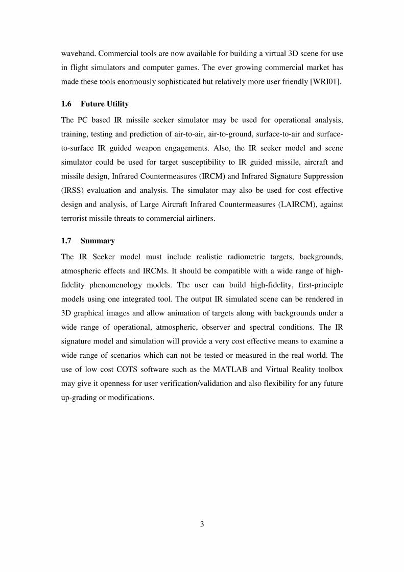
1.6 Future Utility
The PC based IR missile seeker simulator may be used for operational analysis,
training, testing and prediction of air-to-air, air-to-ground, surface-to-air and surface-
to-surface IR guided weapon engagements. Also, the IR seeker model and scene
simulator could be used for target susceptibility to IR guided missile, aircraft and
missile design, Infrared Countermeasures (IRCM) and Infrared Signature Suppression
(IRSS) evaluation and analysis. The simulator may also be used for cost effective
design and analysis, of Large Aircraft Infrared Countermeasures (LAIRCM), against
terrorist missile threats to commercial airliners.
1.7 Summary
The IR Seeker model must include realistic radiometric targets, backgrounds,
atmospheric effects and IRCMs. It should be compatible with a wide range of high-
fidelity phenomenology models. The user can build high-fidelity, first-principle
models using one integrated tool. The output IR simulated scene can be rendered in
3D graphical images and allow animation of targets along with backgrounds under a
wide range of operational, atmospheric, observer and spectral conditions. The IR
signature model and simulation will provide a very cost effective means to examine a
wide range of scenarios which can not be tested or measured in the real world. The
use of low cost COTS software such as the MATLAB and Virtual Reality toolbox
may give it openness for user verification/validation and also flexibility for any future
up-grading or modifications.

5
2 IR RADIATIONS AND SIGNATURE
2.1 Introduction
Electromagnetic radiation ranges from Gamma-rays to Radio-waves. The Infrared
(IR) radiation comes between visible light and microwaves as shown in Figure �2-1
which depicts the major divisions of the electromagnetic spectrum.
Figure �2-1 : The Electromagnetic Spectrum (source [SCH95])
All objects emit IR radiation as a function of their temperature. As an object
gets hotter, it gives off more intense infrared radiation, and it radiates at shorter
wavelengths. At very high temperatures, the objects get red-hot and the thermal
radiations can be observed visually. But even at moderate temperature, the radiation
can be detected or observed as heat but not visible. Below a certain temperature the
human being cannot sense (see or feel) the IR radiation, but the radiations are still
present. Even at low temperature (for example room temperature), the objects radiate
IR energy with different wavelengths and intensities. The IR energy was detected by
Sir William Herschel in 1800 while doing experiment with a prism and sun light
[SCH95]. Although, IR is invisible to the naked eye, it may be observed using IR
detectors and images can then be displayed on TV screens.

6
2.2 Infrared Radiations
The difference between visible and infrared is that in visible scenes the important
parameters are the reflection and external source irradiance, whereas, the infrared
radiation emitted by objects are dependent heavily on the body temperature and the
surface physical characteristics mainly the emissivity and reflectivity of the material.
A hotter object emits more radiation than a cooler one. A rough surface object emits
more radiation than a smooth surface. For detection of a target against the
background, it should either have higher-temperature differential or higher emissivity
differential or a combination of the both.
2.2.1 Plank’s Law for Blackbody Radiations
The Planck’s Law describes the spectral distribution of the radiation from a blackbody
which is usually written as [HUD69].
1
1)( /5
1
2 −= Tce
cTM
λλλ
( �2-1 )
where,
M��� is the spectral radiant exitance, W m-2 �m-1
T is the absolute temperature, Kelvin
� is the wavelength, �m
c1 is the first radiation constant, 3.7418x10⁸ Wm-2�m4
c2 is the second radiation constant, 1.4388x10⁴ �mK
The spectral radiant exitance of a blackbody at temperatures ranging from
200K to 6000K is shown in Figure �2-2. The total radiant exitance, which is
proportional to the area under the curve, increases rapidly with temperature. The
wavelength of maximum spectral radiant exitance shifts towards shorter wavelength
as the temperature increases. The individual curves never cross one another; hence the
higher the temperature, the higher the spectral radiant exitance at all wavelengths.
Integrating Plank’s Law over wavelength limits extending from zero to
infinity gives an expression for the radiant exitance, the flux radiated into a
hemisphere above a blackbody 1 cm2 in area. This is commonly known as the
Stephan-Boltzmann Law. The Stephan-Boltzmann Law applies only to blackbody and
graybody sources [DRI99].

7
( ) 4.. TTM σε= ( �2-2 )
where, � is the emissivity of the blackbody or graybody
σ is the Stephan-Boltzmann’s constant, 5.6697x10⁻¹², Wcm-2K-4
Figure �2-2 : Spectral radiant exitance of blackbody (source [SCH95])
2.2.2 Radiant Properties of Materials
Radiant properties of a material are its ability to absorb, reflect and transmit optical
radiation. The quantities that characterize these actions are absorptance (�),
reflectivity (�) and transmissivity (�). By the conservation of energy, the sum of all
three properties must be equal to one at the same wavelength as all three are functions
of wavelength [SCH95].
( ) ( ) ( ) 1=++ λτλρλα ( �2-3 )
Typically, most solid materials are not transmissive in the IR region. For
opaque materials (�(λ)=0) the above relation reduces as.
( ) ( ) 1=+ λρλα ( �2-4 )
In the IR, the objects provide most of the radiant signal seen by the sensor through
emission while there is low reflectivity. In fact, for an object at thermal equilibrium
(neither gaining nor loosing heat) the absorptance (�) and emissivity (�) are identical
[DRI99].
( ) ( )λελα = ( �2-5 )

8
Therefore, Equation 2-4 can be written as
( ) ( )λρλε −= 1 ( �2-6 )
That implies a higher emissive IR sources has a low reflectivity [DRI99].
2.2.3 Emissivity
The emissivity (�) of an object can at best be that of a blackbody. The ratio of the
emission of an object to that of a blackbody at the same temperature and in the same
spectral interval is defined as its emissivity. The weighted emissivity is defined over a
spectral region and the total emissivity refers to the emissivity over entire spectrum. A
perfect emitter is called a blackbody. It has a constant emissivity of one at all
wavelengths. A graybody has a constant emissivity of less than 1. Emission of real
materials is always lower than that of an ideal blackbody. Figure �2-3 shows the
spectral radiant exitance for a blackbody, a graybody and a selective radiator. A
selective radiator as seen in Figure �2-3 has a value that is wavelength dependant
[ZIS93].
Figure �2-3 : Spectral emissivity of three types of radiators (source [HUD69])
2.2.4 Spectral Radiance
The basic building element, on which all other radiometric quantities are based, is the
spectral radiance. It is the radiant flux per unit area, per unit solid angle and per unit
bandwidth of wavelength. Assuming that the object is a Lambertian radiator, its
radiance (N) can be evaluated from a simple modification to Planck’s radiation Law
Blackbody
Graybody
Wavelength
1.0
0.5
Selective Radiator
Spectral emissivity

9
[RIC02b]. The total radiance within a spectral band is found by integrating the
radiance over the appropriate wavelength [DRI99].
����
����
�−
=�
� �
2
1
2
1
.1
5
1
λ
λ λ
λ λ
λ
ε
πd
e
cN
Tc
( �2-7 )
where, N is the radiance, Wm-2sr-1
� wavelength in �m with λ1 and λ2 represents spectral limits
c1 first radiation constant, 3.7418x10⁸ Wm-2�m4
c2 second radiation constant, 1.4388x10⁴ �mK
T absolute temperature of object, Kelvin
�� spectral emissivity of the object.
2.2.5 Power
Power is the product of radiance times the area times the solid angle to the adjacent
area. The power received at the detector is equal to the product of the target radiance
times the area of the target and the solid angle of the optics as seen from the target.
From Figure �2-4, the power may be equated for different combinations as shown in
the following equation [SCH95].
Error! Objects cannot be created from editing field codes. ( �2-8 )
Where,
P Power received at the detector,
N Radiance,
AT area of target,
AO area of optics,
AD area of detector,
�O,T solid angle of optics as seen from the target,
�D,O solid angle of detector as seen from the optics,
T,O solid angle of target as seen from the optics,
O,D solid angle of optics as seen from the detector.

10
Figure �2-4 : Geometry used in power definition (Source [SCH95])
2.2.6 Solid Angle
The solid-angle (�) is the angle subtended at the centre of a sphere by an area on the
surface of the sphere. The solid-angle is the area on the sphere surface (Ao) divided by
the square of the radius of the sphere (R) [DRI99]. Solid-angle has the units of
steradiance (sr). Many radiometric units are given with respect to the solid-angle. In
Figure �2-5, the solid-angle of optics as seen from the target (ΩO,T) can approximately
be given as.
2, R
AOTO ≈Ω ( �2-9 )
where, radius of the sphere R may represent the distance between target and seeker,
and A0 the area of the seeker optics. Equation 2-9 is a good approximation as R is
usually large and hence Ao is a good approximation to the cross-sectional area. The
area Ao may be written in terms of seeker optics diameter (Do) as,
2
22 .42. O
OO DDRA πππ =�
���
��== ( �2-10 )
Therefore, Equation 2-9 may be written as,
2
2
, .4 R
DOTO
π≈Ω ( �2-11 )
Similarly, in Figure �2-5,
( )22
2
, #1
44 Ff
DODO
ππ =≈Ω ( �2-12 )
�O,T �D,O �T,O �O,D
R f
AO
AD
AT

11
where, OD
fF =# and “f” is the focal length of the seeker optics.
Figure �2-5 : Geometry used in solid angle definition (source [DRI99])
2.2.7 Projected Area
The projected area (Ap) is the area seen by the detector. It depends upon the optics and
the range of the target.
2
... ���
����
�=′′=
f
RbabaAP ( �2-13 )
Where, a and b are detector dimensions and a’ and b’ are their projection. Equation 2-
13 can be derived using the similar triangles shown in Figure �2-6 by the dotted lines.
Figure �2-6 : Projected area calculations (source [RIC02b])
2.3 Sources of Radiation
In any IR seeker missile or imaging system, the main sources of radiation are the
targets and the backgrounds. The targets are the sources which are of main interest.
b
R f
AO
b’
a’ a
�O,T ΩO,D
R f
AO
AD
AT

12
For military systems, generally the targets are aircraft, missiles, ships, ground
vehicles, tanks etc. Depending upon the application, the buildings or even people
could be considered as targets.
Most military targets are man-made sources. The other dominant sources are
the natural sources such as the sun, moon, skylight and star light. The sun is the
primary source of radiation with a temperature of about 6000 K [DRI99]. The solar
irradiance on a target surface changes with a diurnal cycle. Also, the earth, sky and
clouds provide thermal emission and solar reflections (in day time only). The sources
of radiation on military targets are mainly the hot engine parts and the exhaust plume
and the high emissivity metal skin. The engine and exhaust plume produce a large
amount of heat and makes the exhaust section a big source of thermal radiation.
Figure �2-7 shows the various sources of radiation on an aircraft. Similarly, other
military targets also have different sources of radiation.
Figure �2-7 : Sources of radiations on an aircraft (source [POL93])
2.3.1 Sources of Radiation on Jet Aircraft
On a target, the IR signature appears as series of hotter and colder regions. The typical
sources of radiation on jet aircraft are the hot-metal tail-pipe, the exhaust gas plume,
metallic skin and the aerodynamic heating (in case of fast-jet aircraft).
2.3.1.1 Hot Metal Tailpipe and Exhaust Nozzle
Typically there are two sources of radiation from a turbojet engine: the hot metal
tailpipe and the stream of hot exhaust gases known as the plume. The tail pipe
behaves typically as a gray-body with total emissivity of about 0.9 with an exhaust
gas temperature (EGT) up to 900o C and an area equal to that of the exhaust nozzle.

13
The hottest part of the engine is inside the tail-pipe and, therefore, the tail-pipe
radiations are only visible from about 60o cone from the tail aspect. For a non-
afterburning engine viewed from the tail aspect, the radiation from the tailpipe is far
greater than that from the plume. Consequently, the less sensitive seeker heads of
earlier missiles (Sidewinders AIM-9B to 9J and SA-7 etc.) could track only from the
tail aspect while the modern missiles (AIM-9L, Mistral, Magic 2 and Darter etc.) with
more sensitive seeker heads possess an all aspect capability.
2.3.1.2 Hot Exhaust Gas Plume
The exhaust gas plume extends about 130 feet behind the aircraft. The radiation of the
tailpipe is about 25 times that of the plume [HUD69]. The weak plume radiance is due
to several reasons. Firstly, the expansion of its constituent gases upon exit through the
exhaust nozzle leads to its lower temperature in comparison with that of the tail pipe
itself. Secondly, the gas plume is not a blackbody radiator because it is not infinitely
thick and there is no temperature equilibrium within the volume of the gas. Thirdly,
the atmosphere absorbs the same wavelengths as the plume emits. The spectral
distribution of a plume radiation is similar to that of a Bunsen Flame which exhibits
strong spectral emissions in the 2.7 μm wavelength (due to CO2 and H2O) and 4.4 μm
wavelength (due to CO2). The plume principal combustion products also are CO2 and
Figure �2-8 : Exhaust temperature contours for Turbo-jet engine with and without
afterburner (source [HUD69])
H2O, which, unfortunately, are also present in the atmosphere; the plume’s radiation,
therefore, is readily absorbed by the atmosphere. In comparison with the 2.7 and 4.3
μm wavelength, however, the emissions around 4.4-4.6 μm do not suffer from heavy

14
absorptions and contribute to some heat radiation from the plume itself.
Consequently, in comparison with the tailpipe radiation, the exhaust gas plume has
diminishing temperatures as shown in Figure �2-8 (about 760oC at the exhaust nozzle
and reduce to about 66oC at 400 feet). The plume has lower emissivity and poor
transmission through the atmosphere. It is emphasized that the absorption and
emission depends on temperature, pressure, size and the shape of the volume. The
plume’s radiance depends upon the concentration and the temperature of the exhaust
gas molecules which, in turn, depends upon the aircraft’s fuel consumption; therefore,
the radiance of the plume at an altitude of 35,000 feet is only one half of its value at
sea level [WOL78].
2.3.1.3 The After-burner Plume
With afterburner (AB) turned on, the temperature and size of the plume increases
appreciably. Figure �2-8 shows the exhaust temperature contours of a turbojet engine
at full takeoff thrust with and without AB turned on. With AB on the exhaust plume
becomes the dominant IR signature of the turbo-jet aircraft and is viewable from
much large aspect angles [HUD69].
2.3.1.4 Aerodynamic Heating
An object moving at high speed through the atmosphere gets heated. At speeds above
Mach 2, when airflow over a body it often becomes turbulent towards the rear of the
body. Any point on the body where the air stream comes to a complete rest is called a
stagnation point. At stagnation point, the kinetic energy of the moving air is converted
into potential energy in the form of high temperature and pressure the resulting high
temperature produces sufficient radiation to be of interest to the IR system designer.
At speeds above Mach 2, for head-on aspects, the aerodynamic heating becomes the
dominant source of radiation on the aircraft [HUD69].
2.3.2 Sources of Radiation on Ground Vehicles
Military ground vehicles include trucks, tanks, command and communication
equipment and mobile power generating units etc. One of the main threats posed to
the ground vehicles is detection by the Forward Looking IR (FLIRs) systems and
attacked by the IR guided sub-munitions. Because of their high temperature, exhaust
pipes and mufflers may radiate several times as much energy as the rest of the vehicle

15
does. The drive train and the exhaust plume may also radiate sufficient energy to be of
interest as targets. The tyres and tracks may cause secondary heating in the ground
which may contribute to the overall IR signature of the scene. Most ground vehicles
are made of metals and are coated with paints of emissivity of around 0.85 or greater.
In daytime, the IR signature of ground vehicle may also be modified by solar heating
[HUD69].
2.4 Transmission of Infrared Radiation through Earth’s Atmosphere
The energy radiated from the target or source has to pass through some medium
before reaching the sensor. Generally, this medium is the atmosphere. In the visible
region, our ability to view a distant object is not constant and depends upon the
weather conditions. Similarly, the EO/IR sensors are adversely affected by the
changing atmosphere. The influence of the atmosphere on thermal radiation is a
complex process. The earth’s atmosphere is a mixture of many gases and the
existence of these gases in the atmosphere varies with altitude, time and space. The
contents of a typical atmosphere are shown in Table �2-1. The largest constituents are
the Nitrogen, Oxygen and Argon. The other molecules such as Carbon-dioxide, water
vapours, Ozone, Nitrous-oxide and Methane are the key absorbers in the 2-15 micron
band even though they have very minor concentrations [SMI93]. The existence of
water vapours is highly variable from day to day, from season to season, with altitude
and for different geographical locations. Also, the Carbon-dioxide concentration
varies seasonally and is high over vegetation and industrial areas as compare to over
oceans and deserts. The variable nature of these atmospheric gases makes the
prediction of atmospheric propagation at IR frequencies a challenge [SIM93].
2.4.1 Atmospheric Transmittance Calculation Software
The atmospheric transmittance and path-radiance are calculated by using various
numerical models. These models are contained in several atmospheric transmission
codes. The most commonly used codes are LOWTRAN, MODTRAN and
FASCODE. These were developed by Air Force Geophysics Laboratory in
Cambridge, Massachusetts, USA. These codes calculate atmospheric transmittance
and path-radiance based on absorption and scattering phenomena for a variety of path
geometries. All these models developed are only predicting the amount of absorption
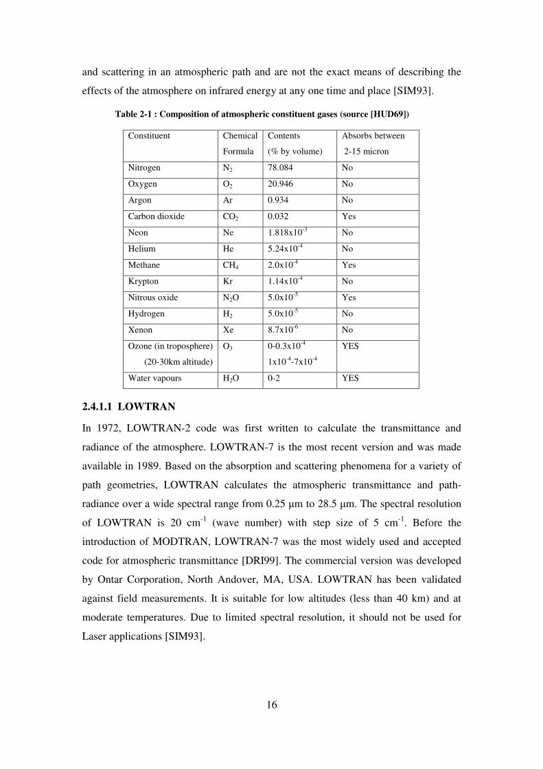
16
and scattering in an atmospheric path and are not the exact means of describing the
effects of the atmosphere on infrared energy at any one time and place [SIM93].
Table �2-1 : Composition of atmospheric constituent gases (source [HUD69])
Constituent Chemical
Formula
Contents
(% by volume)
Absorbs between
2-15 micron
Nitrogen N2 78.084 No
Oxygen O2 20.946 No
Argon Ar 0.934 No
Carbon dioxide CO2 0.032 Yes
Neon Ne 1.818x10⁻³ No
Helium He 5.24x10⁻⁴ No
Methane CH4 2.0x10⁻⁴ Yes
Krypton Kr 1.14x10⁻⁴ No
Nitrous oxide N2O 5.0x10⁻⁵ Yes
Hydrogen H2 5.0x10⁻⁵ No
Xenon Xe 8.7x10⁻⁶ No
Ozone (in troposphere)
(20-30km altitude)
O3 0-0.3x10⁻⁴
1x10⁻⁴-7x10⁻⁴
YES
Water vapours H2O 0-2 YES
2.4.1.1 LOWTRAN
In 1972, LOWTRAN-2 code was first written to calculate the transmittance and
radiance of the atmosphere. LOWTRAN-7 is the most recent version and was made
available in 1989. Based on the absorption and scattering phenomena for a variety of
path geometries, LOWTRAN calculates the atmospheric transmittance and path-
radiance over a wide spectral range from 0.25 �m to 28.5 �m. The spectral resolution
of LOWTRAN is 20 cm-1 (wave number) with step size of 5 cm-1. Before the
introduction of MODTRAN, LOWTRAN-7 was the most widely used and accepted
code for atmospheric transmittance [DRI99]. The commercial version was developed
by Ontar Corporation, North Andover, MA, USA. LOWTRAN has been validated
against field measurements. It is suitable for low altitudes (less than 40 km) and at
moderate temperatures. Due to limited spectral resolution, it should not be used for
Laser applications [SIM93].

17
2.4.1.2 MODTRAN
MODTRAN stands for “MODerate spectral resolution atmospheric TRANsmittance”
or in some text as “MODerate resolution LOWTRAN code” [BER89]. It covers the
infrared, visible and the near-ultraviolet regions and also the microwave region. The
MODTRAN is similar to LOWTRAN but with moderate resolution of 2 cm-1. In
January 2000, MODTRAN-4 was released for public use. Ontar Corporation MA,
USA has developed PcModWin4.0, the WindowsTM based commercial version of
MODTRAN-4. PcModWin4.0 is easy to use and calculates the atmospheric
transmittance and path-radiance at medium spectral resolution [ONT89].
2.4.1.3 HITRAN
HITRAN stands for High Resolution Transmission Molecular Absorption Database. It
is a molecular database with spectral resolution of about 0.001 cm-1. It calculates only
the atmospheric transmittance and does not include aerosols and weather conditions
and is only suitable for calculating molecular absorption in the atmosphere.
2.4.1.4 FASCODE
FASCODE is a line-by-line model that computes the transmission of each absorption
line using the spectroscopic parameters in the HITRAN database. It computes the
atmospheric transmittance and path-radiance with spectral resolution of 0.001 cm-1.
Generally, it is used for very narrow optical bandwidth radiation, such as Lasers and
LIDARs. PcLnWin is Ontar’s WindowsTM based commercial version of FASCODE
[ONT89].
2.4.2 Atmospheric Transmittance
The transmission of the atmosphere present in between the scene and the sensor is
calculated on the basis of the absorption, scattering and refractive-index fluctuations
or turbulence. The turbulence in the atmosphere is due to the temperature, pressure
and density in-homogeneities which may result in blurring and distortion of images. It
is noticeable only when viewing small objects at long distances and has little effect on
near objects [DRI99]. The absorption and scattering are usually grouped together
under the topic of extinction which causes attenuation in the amount of radiant flux
passing through the atmosphere. The transmittance of a path through the atmosphere
can be expressed as

18
( ) ( )xe λσλτ −= ( �2-14)
Where, � represents the transmittance of the atmosphere
is the extinction coefficient, and
x is the path length of the atmosphere
This principle is known as Beer-Lambert Law [DRI99]. Under most
conditions the extinction coefficient () is made up of two components.
( ) ( ) ( )λγλαλσ += ( �2-15)
Where, � is the absorption coefficient account for the absorption by the gas molecules
of the atmosphere and � is the scattering coefficient, accounts for scattering by small
particles suspended in the atmosphere. In IR region of the spectrum, the absorption
poses a far more serious problem than does the scattering posses [HUD69]. The
spectral transmittance measured over a 6000 feet horizontal path at sea level is shown
in Figure �2-9. This curve may be characterized by several regions of high
transmission called atmospheric windows.
Figure �2-9 : Transmittance of atmosphere over a 6000 feet horizontal path at sea level
(source [HUD69])
2.4.3 Atmospheric Path-radiance
As the atmosphere comprises of particles, they thermally emit radiation along the path
in LOS of the source to the detector. The path-radiance of the atmosphere may be

19
calculated by considering atmospheric particles as blackbodies at a particular
temperature. The path radiance becomes negligible as the path transmittance gets
higher (closer to one). Therefore, with a cold clear sky, the path radiance can usually
be neglected but at high temperatures it can cause noticeable effects. Similarly, the
path radiance can be negligible for short path distances [DRI99].
2.5 IR Signature Scene Model Ingredients
The basic building block of the IR signature scene model is the total radiance of each
visible point in the field-of-view of the sensor. The radiance of points hidden behind
any other object will not reach the sensor provided the object obscuring the field-of-
view is opaque. The radiance of any point can have contributions from emission,
transmission and reflection (scattering). Depending upon the material characteristics,
the radiant properties may vary. The opaque surfaces (like an aircraft body or solid
background) have no transmission of thermal radiation through them but they emit
thermally and reflect energy received from the environment. On the other hand, the
non-solids or gases are considered to emit thermally and to transmit but the scattering
may be considered as neglected. Table �2-2 summarizes the effects of various
ingredients of the IR signature scene model. The same are explained in the following
paragraphs.
Table �2-2 : Radiant properties of various sources.
SOURCE EMISSIVITY REFLECTIVITY TRANSMISSION SCATTERING *
Target (Metal) YES YES NO NO
Plume (gases) YES NO YES NO
Background YES YES NO NO
Sky YES YES YES YES
Clouds YES YES YES YES
Glass YES YES NO NO
* or diffused reflections
2.5.1 Targets
The detection of target by IR sensor is based on the thermal contrast between the
target and the background. Although, in opaque objects, in the near and mid-IR bands,
both the reflective and emissive properties are generally equally important, however,
in the far-IR region the contribution due to reflected radiation is usually much smaller

20
and the emissive property of target and background are dominant. The IR radiation
emitted from various direct and indirect sources in the scene, reaches the sensor
through the following mechanisms.
(a) Thermal emission from target corresponding to the body temperature
and in the selected spectral band,
(b) Thermal emission from background corresponding to the background
temperature and in the selected spectral band,
(c) Transmission of thermal radiation from the objects behind the source
(in the case of non-opaque objects),
(d) Reflection of thermal radiation from the target surface. The
environmental sources of reflected radiation are the sun, the earth, the sky and
the clouds,
(e) Inter-reflections caused by very close by targets (in the case of ground
or sea targets only),
(f) Path-radiance of the intervening atmosphere between target and sensor.
2.5.2 Background as Clutter or Source
Depending upon the application, the background may be considered as non-required
clutter or a useful source. In the case of aerial targets (air-to-air or surface-to-air
missile engagements) the background is primarily sky and usually located quite far
from the target. Therefore, the actual background radiance is not as important as the
relative radiance between targets or flares. Whereas, in the case of ground targets (air-
to-ground or surface-to-surface mode) the background radiance is much higher and in
line with the ground target’s radiance. For thermal imaging systems (like FLIR), the
background may also be considered as a source and not clutter. In the case of ground
target, the background is generally earth terrain or man-made structures.
2.5.3 Thermally Static IR Background
The missile-target engagement has a very short flight time (may be a few seconds or
minutes). Therefore, for this short duration, the background temperature or radiance
may be assumed as constant for the simulation. Therefore, the temperature of each
background may be computed for the specific time of the day for which the
simulation is to be performed.

21
2.5.3.1 Clouds
The clouds are non-opaque bodies and behave differently than solid targets and
backgrounds. The clouds can have effects in the foreground as well as in the
background. In foreground, when in the LOS of the target to the sensor, they attenuate
the energy of the target as it passes through the clouds. The transmission of energy
through the cloud depends upon the cloud’s absorption and scattering ability. When in
the background, the clouds themselves act as thermal sources and their emitting
properties are considered.
2.6 Low and High-Fidelity IR Signature Models
Various IR signature models have been presented in the past. Some are low-fidelity
and others are high-fidelity. The fidelity of a model is dependent on its intended
application. Developing a higher fidelity model for a low-fidelity application is not an
appropriate solution. Although, simple first-order straight forward equations could not
determine the exact performance of a system, it is considered sufficient for evaluating
the lock-on range of a point source target. The models presented in references
[KIN00],[RIC02b],[YAN02],[RIC03] and [BEN04] are simple and easy to use for
low fidelity models. On the other hand, high-fidelity IR signature models presented
are time consuming and heavy on computations. The IR signature scene fidelity
improves in pace with the increase in the computational capabilities [GON03]. Unlike
point source based seekers, the modern image based missile seeker needs high-fidelity
modelling with more accurate and realistic imagery. These high-fidelity models
contain highly detailed terrains, man-made structures, atmospheric effects, detailed
target geometry and thermal signature models [MUU95]. To make it more realistic,
the “special effects” such as exhaust gas plume, dust, smoke and clouds are added in
these models [HOO91]. The NATO Infrared Air Target Model (NIRATAM) and
NATO’s NPLUME are the examples of high-fidelity modelling [BAK99], [DEV01]
and [CUR02].
2.7 Conclusion
All objects emit energy in the IR portion of the electromagnetic spectrum. The energy
radiated from any object depends upon its property to absorb, reflect and transmit
radiation. The temperature of the body, emissivity and reflectivity of the surface are
the dominant factors for IR signature modelling. The IR energy attenuates as it passes

22
through the atmosphere. The IR energy received at the detector comprises of
radiations from target, background radiations and reflected energy from other sources.
Knowledge of IR signatures is fundamental to any development and analysis in the
fields of heat seeking missiles and infrared countermeasures. For IR signature
modelling the radiometric properties of the material, the temperature of each sub part
of the objects present in the scene, the spectral radiance and the total power received
at the detector after atmospheric attenuation are the important parameters which needs
to be considered. The details of these parameters are given in Chapter-6.

23
3 IR GUIDED MISSILES
3.1 Introduction
Infrared guided missiles have been among the most deadly threats in all recent
conflicts. Also they have been responsible for most of the military and civilian aircraft
downed in the last several decades. Since the birth of the first un-cooled reticle seeker,
missile technology has advanced considerably to the latest multi-colour array imaging
seekers.
3.2 Evolution of Heat Seeking Missiles
The early heat seeking missile used un-cooled detector technology, operating in the
near-IR waveband. These missiles typically see high temperature targets or central
regions of the exhaust plume. Whereas, the next generation cooled detectors have
higher sensitivity in the mid-IR band and can detect warm skin of an aircraft or the
hot exhaust gas plume. The latest missiles have imaging seekers working in the mid-
IR or the far-IR wave band. The following paragraphs explain the evolution of heat
seeking missiles.
3.2.1 First Generation Seekers
Figure �3-1 is a block diagram showing the basic layout of a first generation seeker
system. This type of system is often referred to as a spin-scan seeker.
Figure �3-1: Block Diagram of First Generation (Spin-Scan) Seeker

24
Infrared radiation from the scene passes through the dome and is imaged via the
Cassegrain telescope onto a spinning (rotating) reticle. The detector (usually un-
cooled Lead Sulphide) then converts this chopped IR signal into an electrical signal.
A pick-off is used on the reticle to enable phase sensitive detection to allow the error
signal to yield pitch and yaw. An automatic gain control (AGC) is used to prevent
saturation of the electronic amplifiers and filters. The gimbaled head allows field-of-
regard (FOR) typically in excess of 90o.
Several different reticle designs have been developed to optimise their
tracking capability with the one of the simplest referred to as the rising-sun reticle,
see Figure �3-2. It consists of a null-phase portion that only transmits 50% of the
radiation, to set the AGC within the seeker and generate the phase with respect to the
pick-off. The other section alternates between 100% and 0% transmission to produce
an amplitude modulated carrier. The closer the image is to the axis the smaller the
amplitude of the square wave produced. Hence this produces a time-referenced
waveform that provides spatial information of the image with respect to the optical
axis of the seeker (centre of the reticle).
Legitimate targets are distinguished from background IR sources by the degree
of amplitude modulation. Large sources, such as clouds, produce little (if any)
modulation, as no single hot spot can be identified as the reticle rotates through its
target sensing section.
Figure �3-2 : Rising-Sun Reticle showing Amplitude Modulation and Null-Phase Sector

25
The un-cooled Lead Sulphide (PbS) detectors usually used in this generation
of seekers have a peak sensitivity at < 3μm. These systems therefore typically operate
in the near-IR 2-2.7μm atmospheric window (see Figure �3-3), which tends to limit
such missiles to rear engagements as the detector can only discern the hot metal parts
of the engine and the hotter water emission in the plume.
Figure �3-3: Typically Atmospheric Transmission with IR Emitters
Improvements to the rising-sun design included adding curved radials to the
reticle to reduce the chance of being spoofed by straight edge IR emitters such as the
horizon (see Figure �3-4).
Figure �3-4: Improved First Generation Reticle
0
0.2
0.4
0.6
0.8
1
2 3 4 5 6 7 8 9 10 11 12
Wavelength (μμμμm)
ISA
Atm
osp
her
ic
Tra
nsm
issi
on
at
1km
(%
)
Near IR Mid IR Far IR
CO2 H2O CO2 /
H2O
Very Hot
Components,
Plume,
Solar
Reflections
Hot Components,
Plume,
Some Fuselage General Fuselage
Ambient
Temperature

26
An example of a 1st generation IR missile is the Strela-2 (SA-7 ‘Grail’).
Originally fielded by the Soviet military in 1968, the SA-7 is one of the simplest
versions of this type of weapon (see Figure �3-5). Widely proliferated, it poses a major
threat to aircraft without any countermeasure (CM) systems, although, it is limited to
rear aspect engagements. It has an impact fuse and has a minimum engagement
altitude of 50m. These types of weapon are often referred to as a man-portable air
defence systems (MANPADs).
Figure �3-5: SA-7 a First Generation Seeker System (source [FAS07])
Once this type of seeker has manoeuvred the missile body so that the target is
in the centre of its FOV, it suffers from axial insensitivity and starts to hunt back and
forth. This is a result of the seeker effectively losing all fine directional information
on the target because of a lack of amplitude modulation at the centre of the reticle.
This leads to poor hit probabilities for engagements with even a small level of
crossing rate. This axial insensitivity was removed by rotating the optical axis as used
in second generation systems.
3.2.2 Second Generation Seekers
Second generation seekers (often referred to as Con-Scan) used a stationary reticle
with a rotating optical system to yield a square wave on axis and hence remove the
axial insensitivity of the first generation systems. This can be seen in Figure �3-6,
where the secondary mirror is tilted and the primary and secondary mirror are rotated.
This yields a nutation circle image motion on the stationary reticle.

27
Figure �3-6: Second Generation Seeker Schematic
The reticle in the second generation system is usually referred to as a wagon
wheel reticle and can be seen in Figure �3-7. When the target is on-axis a centred
nutation circle is produced, yielding a constant square wave (with no frequency
variation – this is the tone played into the earpiece of many systems). As the target
moves off-axis a frequency modulated waveform is produced. Again a pick-off from
the rotating optical system is used to enable the computation of the axial error in
terms of pitch and yaw.
More sensitive detector materials were also introduced to facilitate all-aspect
tracking. These cooled detectors, used materials such as Indium Antimonide (InSb)
for detection in the mid-IR 3-5μm atmospheric window (see Figure �3-3). Operating
at longer wavelengths allowed cooler parts of the engine, hot parts of the airframe,
and the cooler CO2 emissions in the exhaust plume to be detected, thus allowing
wider angles of engagement. There are many options for cooling the detector,
arguably the most common method is via a Joule-Thomson (JT) cooler with a small
bottle of Argon or Nitrogen or dry air.

28
Figure �3-7: Wagon Wheel Reticle Showing Frequency Modulation Outputs
An example of 2nd generation system is the ubiquitous AIM-9L (Sidewinder) see
Figure �3-8. Other examples of this type of system in the MANPADS role are the US
Redeye and basic Stinger and the Soviet Strela-3 (SA-14). The Chinese QW-1
(Vanguard) is also probably this type of generation system, as is the Pakistani-built
version Anza Mk-1.
Figure �3-8: AIM-9L a Second Generation Seeker System (source [FAS07])
There is however another type of second generation (con-scan) seeker as
typified by the French MANPADS Mistral. This still uses a nutation circle but does

29
not have a reticle and instead has four detectors arranged in an open-cross formation
to yield the frequency modulation (FM) output (see Figure �3-9). Again when the
target is on axis, the system produces a square wave (four equi-spaced detector
outputs); whereas, when the target is off axis, a frequency modulated square wave is
produced (unequal spacing of the detector outputs).
Figure �3-9: Open-Cross Detector Showing Frequency Modulation Outputs
The Soviet Igla (SA-16 Gimlet) and Igla-1 (SA-18 Grouse) are possibly this
type of seeker as is the Chinese QW-2 and the Pakistani built Anza Mk-2.
3.2.3 Third Generation Seekers
The third generation seeker systems are often referred to as Pseudo Imaging Systems
as they rely on creating a simulated image of the target by moving the IR signal over
the detector. This is achieved by rotating a couple of offset mirrors or Risley prisms
(see Figure �3-10) to produce a specified pattern on the detector. The shape of the scan
pattern varies according to the relative rotation rate and direction of rotation of the
mirrors or prisms.
Figure �3-10: Risley Prisms to Generate Pseudo Image Scanning
Axis of Rotation
Detector Rotating Prisms

30
Scan patterns are optimised to meet various specifications although the most
widely used is the Rosette scan due to its re-visiting the axis after each petal of the
rosette (see Figure �3-11).
Figure �3-11 : Resley Scan Patterns
The major advantages of this type of system are increased lock-on range and
robustness to countermeasures in part due to the smaller instantaneous field-of-view
of the detector. An example of a 3rd Generation IR missile is the MANPAD Stinger-
RMP (reprogrammable microprocessor). It has more robust flare rejection mechanism
including using a dual mode IR/UV detector in its rosette scan. The UV detector
looks for a negative contrast signal as the airframe blocks the Rayleigh scattered solar
radiation. The IR signal from the plume has to coincide with the recovery of the UV
signature for a valid target enable. The IR detector is JT cooled with Argon and is
operational in less than 5 seconds. See Figure �3-12.
Figure �3-12: Stinger-RMP a Third Generation Seeker System (source [FAS07])
Linear Rosette Circular Spiral

31
It is also claimed by some that the Soviet SA-16/SA-18 are also an example of
this generation of seeker by virtue of the fact that a UV detector is used in its
countermeasure (guard) channel.
3.2.4 Fourth Generation Seekers
The fourth generation of seekers are characterised by multi-element detectors that
produce an image of the target on the focal plane. Often referred as Imaging Infrared
(I2R) seekers, the individual detectors can either be arranged linearly, with a scanner
to produce an image, or as a staring focal plane array. A further development of this
technology is likely to see the use of multi-colour infrared seekers thus increasing
their defence against IRCMs. Although more robust and less susceptible to jamming,
array seekers are currently far more expensive to produce than all the earlier
generations and have not proliferated to the same extent. Image size and computing
power is also an issue with this generation of seeker. Obviously the smaller the
number of pixels in the image the easier the computation task but the poorer the
resolution on the target (see Figure �3-13).
Figure �3-13 is an illustration of a typical target at range on a starring array
whilst Figure �3-14 is an illustration of how advanced multi-colour detectors may
extract spectral information from, for example, the plume.
Figure �3-13: Illustration of a Typical Target on a Staring Array

32
Figure �3-14: Spectral Output of a Typical Plume
There are many examples of 4th generation IR missiles being produced. On the
MANPAD front, the US Stinger Block-2, which was to be fielded circa 2000, was
consist of a 128x128 or 256x256 3-5μm Indium Antimonide (InSb) staring focal
plane array, primarily to increase its acquisition capability (especially in ground
clutter). Currently though, it is fair to say that most 4th generation systems are in the
air-to-air role, for example:
(a) The German IRIS-T allegedly uses a scanning array of two staggered
64 element linear rows of InSb detectors working in the 3-5μm mid-IR region.
It has an 180o FOR and an active Laser fuse.
(b) The Israeli Python-4 has a stabilized seeker slaved to the pilots helmet
mounted sight with 60o off-boresight capability and allegedly uses a two
colour all aspect IR staring array. (Python-5 is claimed to be a Hughes
128x128 staring focal plane array in 3 IR bands).
(c) The UK ASRAAM uses a 128x128 staring array of InSb detectors
working in the 3-5μm mid-IR region. It has an 180o FOR, can be cued by the
pilot's helmet and has demonstrated the ability to select an aim point on the
target aircraft. It has an impact and active Laser fuse.

33
(d) The US AIM 9X (Sidewinder-next generation) is currently in its last
year of Engineering and Manufacturing Development. It is alleged to have the
same staring array as ASRAAM and is cued by the pilot’s helmet sight. It
claims its adaptive and advanced processing gives it superior target acquisition
and IRCM rejection capabilities.
3.3 Missile Tracking Techniques
The aim of a tracker is to measure errors or deviations from the bore-sight and send
signals to the control system to reduce these errors to zero. Mainly, there are two
types of imaging trackers, Gated Video Tracker (GVT) and Correlation Tracker.
3.3.1 Gated Video Tracker
The Gated Video Tracker (GVT) evaluates each resolution element with in the FOV
against some target criterion and maintains a stable sensor-to-target line-of-sight
(LOS). Initially, the target is pre-acquired by some means. Once the target is acquired,
the tracker locks-on to it and maintains the LOS. It has a closed area around the target
where a tracking-gate is applied which works on the target edges and selects a
rectangle around it. The gate can be made up of more realistic contours matching the
target shape. The aim-point changes as missile-to-target range reduces. As the target
comes closer it is more resolvable. The aim-point goes for higher contrast areas within
the target such as a shining canopy in the visible or hot tailpipe in the case of IR
detectors [DUD93]. Several methods for target location estimation have been
developed. The most common of these is the centroid tracker.
3.3.1.1 Binary Centroid Tracker
The binary centroid of a segmented image is analogous to the centre-of-mass of a
discrete distribution of unit masses. Consider the segmented image shown in
Figure �3-15, where each pixel has been assigned a value of 1 if it corresponds to the
target, and a value of 0 otherwise. It converts the image into a binary go-no-go video-
map. The binary centroid tracker is an attractive option for applications that require a
low-cost tracker with only modest performance capabilities. Most early imaging
trackers used binary centroid because high-performance digital hardware was not
available [DUD93]. Binary centroid tracking algorithms work well for situations
where targets have high contrast with respect to background.

34
Figure �3-15 : Binary centroid of target image
3.3.1.2 Intensity Centroid Tracker
The architecture of the intensity centroid is similar to that for the binary centroid, but
it does not employ the video-map to classify target and background pixels. Instead, it
uses intensity information directly in the centroid calculation. This means that pixels
with higher intensity values will be given more weight as compared to the pixels with
low intensity values. One important application of the intensity centroid algorithm is
high-accuracy point-target tracking [DUD93]. However, the accuracy of the intensity
centroid tracker is extremely sensitive to the size of the target-gate. If the target-gate
is large, then pixel values containing mostly noise are included in the centroid
calculation, which degrades the accuracy [DUD93].
3.3.1.3 Threshold Intensity Centroid Tracker
The accuracy of the intensity centroid tracker can be improved if a video-map is used
to eliminate pixel values not clearly associated with the target. The video-map acts
like a pixel-level gating function in the centroid calculation. This type of intensity
centroid is some times called a threshold intensity centroid [DUD93].
3.3.2 Correlation Tracker
The GVT is effective with a low-clutter background. For an image full of background
clutter or other IR sources, then correlation trackers may be used. They are more
0 0 0 0 0 0 0 0 0 0 0
0 0 0 0 0 0 0 0 0 0 0
0 0 0 0 0 0 0 0 0 0 0
0 0 0 0 0 0 0 1 1 0 0
0 0 0 0 0 0 0 1 1 1 0
0 1 1 1 1 1 1 1 1 1 0
0 1 1 1 1 1 1 1 1 1 0
0 0 0 0 0 0 0 0 0 0 0
0 0 0 0 0 0 0 0 0 0 0
Target
Target Gate
Binary
Centroid
Background

35
complex than the GVT and need prior knowledge of the desired target. In correlation
tracking frame images are compared with a desired target image which is stored in
memory. The offset produced due to matching generates the tracking error signal. The
tracker points in the direction of the best match. The correlation tracker needs larger
memory and faster computation capability. They are generally used for high value
targets [DUD93].
3.4 Missile Guidance
The missile guidance is used to increase the Single Shot Kill Probability (SSKP) of a
warhead. An unguided warhead will typically have excessive miss-distance. It is
mainly due to number of factors including: the incorrect direction at launch, wind and
weather disturbances in the flight path and the movement of the target. The solution to
all of these limitations is to use guidance system to reduce the miss-distance and
hence improve the SSKP [ROU00]. Missile guidance provides steering commands to
the missile control surfaces so that the missile can successfully intercept the target.
The selection of the guidance technique largely depends upon the size and speed of
both the target and the missile. Missile guidance against large slow moving or quasi-
static targets is comparatively simple. However, against small, fast and highly
manoeuvrable targets we would need to have sophisticated and rapidly responding
missile to enable a successful interception. There are basically three categories of
guidance. These are Line-of-Sight guidance, homing guidance and navigation
guidance. A further category of guidance, which combines more than one type of
guidance, is called compound guidance.
3.4.1 Line-of-Sight Guidance
The Line-of-sight (LOS) guidance is the simplest method and most widely used for
guidance against targets moving in straight lines. It needs a high sustained turn-rate to
successfully track manoeuvring or crossing targets. A missile using the LOS-guidance
has a complex launcher but the missile itself is simple. The LOS-guidance is further
divided into two types. These are the Command-to-LOS (CLOS) guidance and the
LOS-beam-rider (LOSBR). In CLOS systems, the operator visually acquires the target
and guides the missile into the target either by radar or an optical tracking link. CLOS
systems are not usually susceptible to countermeasures designed for IR missiles.
Examples of CLOS systems are the British Blowpipe and Javelin systems. In LOSBR

36
an operator tracks the target and maintains a “cross-link” on the point of desired
impact. The missile tracker calculates angular deviation from the centre of the beam.
A steering command is generated in the missile which guides the missile to the target.
The beam riders are difficult to jam once they have been launched. The examples of
beam-riders are the Swedish RBS-70 and British Starstreak HVM.
3.4.2 Homing Guidance
In homing guidance the tracker is on the missile itself so it is called “two-point
guidance”. The homing guidance is a closed-loop system in which the target data and
missile position are observed continuously and steering commands are sent to the
missile control surfaces. For moving targets, a feedback system is needed to
constantly record the target position which is called guide-on-the-target (GOT). The
homing missile sensor is called a “homing-eye”, “homing-head” or more commonly
the “seeker-head”. The seeker-head tracks the target by detecting energy emitted
from, or reflected by the target. There are three forms of homing guidance available.
These are the active-homing guidance, which self illuminate and track their target,
semi-active which guides onto energy reflected off the target which was transmitted
by some other source which could be on the launch platform and finally passive-
homing guidance which tracks emissions coming out from the target like “heat
seeking” and “anti-radiation”. The US Stinger and Russian SA-7 SAM’s are the
examples of the passive-homing guidance.
3.4.3 Navigational Guidance
In navigational guidance (NG), the missile carries the guidance-computer which
obtains information concerning missile position from instruments or sensors which
are also installed on the missile. The NG directs the missile onto a location in space
planned in advanced and stored in memory. The most common type of navigational
guidance is Inertial Navigation system (INS) which generally used in cruise missiles
[ROU00].
3.4.4 Compound Guidance
Each type of guidance has its own advantages and limitations. To have an optimized
guidance system which suits the specific requirement, combinations of different
guidance systems at different stages of flight can be used. Missiles are designed with

37
two or more guidance systems working in parallel or in sequence. One such example
is use of Inertial Navigation (IN) during the cruise phase and then shifting to homing
guidance near the terminal phase.
3.4.5 Guided Missile Trajectories
The path a guided weapon follows from its launch point to the target is called its
trajectory [ROU00]. Following are the types of trajectories which a missile can
follow.
3.4.5.1 Straight-line Trajectory
In the straight-line trajectory a straight path between launcher point and impact point
is established before launch, as seen in Figure �3-16. The straight-line trajectory
is suitable for fixed or slow moving targets at short ranges. In some cases this
technique may be used for the initial flight path of a missile which subsequently
follows a ballistic trajectory.
Figure �3-16 : Straight-line Trajectory
3.4.5.2 Line-of-sight Trajectory
The Line-of-sight (LOS) trajectory is shown in Figure �3-17. At any time the LOS is
the line joining the observation point (launcher) to the position of the target at that
instance. A missile following the straight-line trajectory may require little ability to
accelerate laterally. Whereas, the LOS missile will normally follow a curved
trajectory requiring considerable lateral acceleration (LATAX) capability. The LOS
trajectory is commonly used in short range missiles [ROU00].
3.4.5.3 Proportional Navigation Trajectory
Generally, homing guidance missiles use proportional navigation trajectory. It
establishes a sight-line from the missile to the target at all times as shown in
Figure �3-18. The rate-of-turn of the sight-line is used to move the missile controls.
The rate-of-change of the flight-path is directly proportional to the rate-of-turn of the
sight-line [ROU00]. In proportional navigation the tracker is on the missile so it does
Missile Target

38
not need to have any link with launcher. The proportional navigation trajectory is used
for fast moving aerial targets in air-to-air or surface-to-air modes.
Figure �3-17 : Line-of-sight Trajectory
Figure �3-18 : Proportional Navigation Trajectory
3.4.5.4 Pursuit Course Trajectory
Perhaps the oldest and simplest type of flight path is that of the pure pursuit case also
called “hound-and-hare” course [LOC55]. In pure pursuit course, the missile always
Missile
Path
Target
Path Sight Line
Impact
Point
Missile
Path
Target
Path Sight Line
Impact
Point

39
looks towards its target as a dog chasing a cat and never plans ahead to intercept the
target. The sight line at any one instance can be found by drawing a tangential to the
flight path of the missile at that interval. Figure �3-19 shows the pure pursuit course
trajectory.
Figure �3-19 : Pure Pursuit Course Trajectory
3.4.5.5 Cruise Trajectory
Cruise is a pre-selected or defined path on which the missile moves at constant speed
and height for most of its journey from launcher to target. It is, generally, used for
long range cruise missiles. For long distances, the missile may go through a number
of phases involving change from one height to another and perhaps a change in speed,
but then each phase will be a segment of cruise trajectory [ROU00].
3.4.5.6 Ballistic Trajectory
Ballistic trajectory is the free fall trajectory caused by only the gravitational force as
no motor or force is applied to create thrust or LATAX. Inside our atmosphere it is
difficult to follow this trajectory, but in space where there is no aerodynamic drag a
missile can follow ballistic trajectory [ROU00].
Missile
Target
Sight Line

40
3.4.6 Proportional Navigation Guidance
The origin of proportional navigation guidance (PNG) is probably from the naval
tradition of using this navigational technique for avoiding the collision of ships at sea
with stationary or moving ships [GAR80]. In ships it is used for avoiding collision
whereas, in missile it is used to encourage collision. In December 1950, the Lark
missile was the first system developed using PNG, since then it has been the most
widely used guidance system in all radar, infrared and TV guided missiles [ZAR02].
In short range homing missiles PNG is the most widely used guidance technique.
PNG uses the LOS-rate between the missile and the target and the closing velocity (or
time to go) as the basis for the steering commands. It generates command acceleration
proportional to the LOS-angle-rate in an effort to form a collision course. PNG is
faster and more efficient than LOS-guidance as it looks ahead of the target and
reduces the intercept time and the demands on lateral acceleration. Still, it is not very
effective against highly manoeuvring targets but it is simple to implement and does
not require information about target range and location.
3.4.6.1 Augmented Proportional Navigational Guidance
As mentioned above, PNG has its limitation against highly manoeuvring targets.
Augmented-PNG (APNG) is a modified version of PNG for highly manoeuvring
targets. It is a higher-order guidance law which uses knowledge of the target range,
velocity and acceleration. In APNG the total lateral acceleration requirements are
much less as compared to PNG. Therefore, for strategic applications APNG is a more
efficient guidance law then PNG [ZAR02].
3.4.6.2 Proportional Navigation Law
Proportional navigation law states that the rate-of-change of the missile heading or the
trajectory is directly proportional to the rate-of-change of the sight-line between the
missile and the target [GAR80].
••
= θθ km ( �3-1 )
where, m
•
θ is the rate-of-change of the missile trajectory
•
θ is the rate-of-change of the sight-line
k is the navigation constant

41
To understand proportional navigation we can take two cases using Equation 3-1. In
first case, if the value of the navigation constant is kept as unity (k=1), the rate-of-
change of the missile trajectory will be equal to the rate-of-change of the sight-line.
That implies that at any one instance a tangent drawn to the missile flight path must
remain coincident with the sight-line. A tangent to flight-path indicates the
instantaneous direction of the flight path at any one point in time. The type of
trajectory caused by this is the pure pursuit course. In the pure pursuit course, as the
missile is not anticipating the target future position, it needs to put in more efforts in
terms of lateral acceleration towards the end of the flight path near impact. On the
other hand, if the value of navigation constant is kept at four (k=4), then the rate-of-
change of the missile trajectory will be four times the rate-of-change of the sight-line.
The sight-line rate will reduce as the engagement proceeds. As a lead is established,
the missile manoeuvres more in the beginning and it needs to turn less towards the
impact. That implies that the overall missile lateral acceleration requirements will be
less. Figure �3-20 shows the difference between the pure pursuit course and
proportional navigation.
Figure �3-20 : Pure pursuit and Proportional navigation explained
k=1
k= 4
(a) Pure pursuit (b) Proportional Navigation
Missile
Path
Missile
Path
Target Path Target Path

42
3.4.7 Pursuit Course Guidance
One of the simplest ways of intercepting a target is to keep pointing at the target with
missile having a greater speed than that of the target. Pursuit course guidance is the
special case of proportional navigation, in which the navigational constant “k” is kept
at unity (k=1). This means the missile always aims towards the instantaneous location
of the target and never attempts to aim ahead as in the case of proportional navigation
as shown in Figure �3-21 (a) and (b).
Figure �3-21 : Pure Pursuit Course Guidance
In Figure �3-21(b) by using components of the missile velocity and target
velocity (parallel and perpendicular to the sight-line) we can write the following two
equations [LOC55]:
( ) ( )mMTTM CosVCosVR θθθ −−=•
( �3-2 )
( ) ( )
TM
mMT
R
SinVSinV θθθθ
−+−=
•
( �3-3 )
where, RTM is the missile to the target instantaneous distance
VT is the target velocity
VM is the missile velocity
θ is the angle target is making with sight-line
RTM
VM
VT θ Target
Missile θm
RTM
VM
VT θ Target
Missile θm
θ θ
(a) Pure Pursuit Course Guidance (b) Proportional Navigation Guidance
Sight-line Sight-line

43
θm is the angle missile is making with horizontal reference or the direction
of the target velocity
By integrating Equation 3-1 we get
om k θθθ += ( �3-4 )
Where, θo is the initial angle of missile trajectory. If k is unity and θo is zero then
Equation 3-4 becomes:
θθ =m ( �3-5 )
Which is the condition for pure pursuit course guidance. Figure �3-21(a) shows this
special case of proportional navigation. Putting θθ =m in Equations 3-2 and 3-3 we
can get the equations for pursuit course guidance as [LOC55]:
( ) MTTM VCosVR −=•
θ ( �3-6 )
( )
TM
T
R
SinV θθ −=•
( �3-7)
Dividing Equation 3-6 with Equation 3-7 and rearranging we get [LOC55].
( )•
•
−= θθθ CotpCoR
R
TM
TM sec ( �3-8)
Where “p” represent the velocities ratio VM/VT and by integrating Equation 3-8 we
get [LOC55].
( )
( )p
p
TMCos
SinKR
θ
θ
+=
−
1
1
( �3-9)
where, constant ( )( ) 1
1−
+= p
o
po
Sin
CosK
θ
θ.
This equation of RTM is for decreasing range [LOC55].
3.5 Missile Controls
The commands generated by the missile guidance system are fed to the control
surfaces for moving the missile in the desired direction in three dimensional spaces.
The up/down, left/right and forward/backward movement of the missile are achieved
with translation in three axes orthogonal to each other and combined with rotation

44
around these three axes of pitch, yaw and roll. These six movements are independent
of each other and are specified as six degrees-of-freedom (6DOF). Considering three
orthogonal translation axis along the body of the missile as shown in Figure �3-22, the
up/down rotation along lateral axis is called “pitch”, the circular movement along
body axis is the “roll” and the left/right movement along the vertical axis is the “yaw”
movement.
Figure �3-22 : Missile six degrees-of-freedom
3.6 Missile Aerodynamics
The atmosphere is not homogeneous and has different pressure and temperature
regions. Missile performance and manoeuvrability is affected by atmospheric
conditions. In the following paragraphs some of these effects related to missile
modelling and performance are discussed.
3.6.1 Aerodynamics Drag
The total aerodynamic drag produced due to the movement of the missile in the air is
sum of three factors; the skin friction, the pressure drag and the drag induced due to
lift [ROU00]. The drag force applied on the surface of the object flying in the air is
proportional to the square of the velocity ( 2VFD ∝ ). The force produced due to the
aerodynamic drag can be written as [AND00]:
2DVFD = ( �3-10)
Yaw
Roll
Pitch
Body Axis
Lateral Axis V
ertical Axis
Z
X
Y

45
Where,
ACD D.21 ρ= ( �3-11)
FD is the force due to the aerodynamic drag
V is the velocity of the missile relative to the air
� is the density of the air
CD is the drag coefficient
A is the cross-sectional area
However, it is important to know that at speeds greater than Mach 1, the drag
coefficient is velocity dependent and behaviour of the drag changes.
3.6.1.1 Skin Friction
Skin friction is caused by the viscosity of the fluid through which the object is
passing. The viscosity causes the shearing of the boundary layers which generates
friction. The higher the viscosity the higher the friction produced. Air is not very
viscous so the shearing forces are not very large, but due to the overall shearing force
produced from a big surface area, the skin friction may contribute considerably to the
over all missile drag.
3.6.1.2 Pressure Drag
The sharp corners of the missile or sudden changes in the cross-sectional shape due to
manoeuvre etc. will cause wakes which generates a force at the back of the surface
thus causes drag. The body of the missile should be a smooth rounded streame-line
surface to keep pressure drag low.
3.6.1.3 Lift Induced Drag
Trailing vortices are produced at the back of lift generating surfaces due to down-
wash and up-wash motion of the air. This motion causes a drag which is called lift
induced drag.
3.6.2 Lateral Acceleration of the Missile
Lateral acceleration (LATAX) is the sideways acceleration applied in two dimensions
(i.e. pitch and yaw) to steer the missile in the desired direction. LATAX is usually
46
produced by aerodynamic forces acting on control surfaces. The LATAX depends
upon the missile velocity and the distance between the missile and the target. The
LATAX requirements generally increase with an increase in the sight-line angle. For
small angles, the LATAX requirements are reasonable but for larger angles between
50o to 90o the LATAX requirements are much more severe. LATAX is a very
important factor in the performance of missile. The design of any missile guidance
system depends upon its lateral acceleration capabilities. Generally, surface-to-air and
air-to-air missiles require high LATAX capabilities as they require high
manoeuvrability to catch fast flying targets. In command guidance system the lateral
acceleration tends to increase towards impact. Whereas, in proportional navigation the
LATAX demands tends to decrease as it reaches the target provided the target does
not manoeuvres.
3.7 Missile Fuses
Lethality of the warhead depends upon its lethal radius, the radius of a hypothetical
sphere around the warhead within which any target will receive fatal damage. In
reality, warheads are directional, so their lethal zone is typically a lobe shape instead
of a sphere. The purpose of a fuse is to activate the warhead once the desired target is
within its lethal radius. The effectiveness of the warhead therefore depends upon the
performance of its fuse. There are mainly two types of fuses, the impact fuse which is
the simplest and the more advance and complex proximity fuse. The most common
proximity fuses used are radio proximity and active laser fuse. They do not need to
impact the target but, trigger once the target enters the volume of space surrounding
the missile. A delay is implemented to allow the target to come inside the lethal
volume. Proximity fuses have a limitation in that they can inadvertently operate from
for example the proximity of low level terrain, buildings or ship masts which are not
the intended targets.
3.8 Summary
The first generation “spin-scan”, second generation “con-scan” and third generation
“pseudo-imaging” based seeker’s output can be modelled using different techniques.
However, in my work I have implemented the fourth generation “imaging IR” seeker
using virtual reality modelling techniques. The gated-video tracker (GVT) and
correlation trackers are used for generating error signals. In my work I have

47
implemented the binary and intensity centroid tracker algorithms. The IR homing
guidance was implemented using pursuit course guidance which is the special case of
proportional navigation guidance (PNG). The missile lateral acceleration is
implemented based on the missile speed and load factor. The details of all these
algorithms are given in Chapter-8.
3.9 Conclusion
Between 1981 and 1998, the IR guided missiles accounting for approximately 55% of
worldwide combat aircraft losses [PAR04]. The threat from surface-to-air and air-to-
air missile to the flying platforms is real. The biggest threat to aircraft is the
MANPADs. IR homing missiles are fire-and-forget passive systems. They require no
special fire control system. They are relatively cheap to manufacture and easy to
operate. The new generations of IR guided missiles have an all-aspect attack
capability and an improved immunity to flares.
49
4 INFRARED COUNTERMEASURES
4.1 Introduction
During the Russian invasion of Afghanistan, the Mujahideen downed 269 Soviet
planes with 340 shoulder fired SAMs [BOL04]. In the last 25 years, there have been
35 recorded attacks on civilian aircraft using shoulder fired SAMs [BOL04]. While
SAMs and AAMs represent a serious threat to combat and civilian aircraft, they can
be defeated by the selection of appropriate countermeasures and evasive manoeuvres.
Ideally, the launch of a missile should be avoided, if this is inevitable then, exploit the
known weaknesses of the missile system to defeat it [TAY05].
4.2 Defence against Heat Seeking Missiles
There is a wide range of IR seeker missiles available in the world including the latest
high sensitivity, smart seekers and ideally, an IRCM system must counter all these.
However, there is a high probability of meeting a less capable threat of the more basic
technology as compare to the latest state-of-the-art seekers. Defence against heat-
seeking missiles involves the measures taken to make the missile exceed its design
performance limitations so that it can either not be launched at all or, if already
launched, it cannot successfully intercept its target. Anti-missile defence, therefore,
can be sub-divided into two categories, namely pre-launch defence and post-launch
defence.
4.2.1 Pre-Launch Defence
The aim of the pre-launch defence is to deny the enemy the missile launch envelope
(MLE). This could be achieved, for example, by moving fast and using terrain to
avoid being tracked.
4.2.2 Post Launch Defence
If the pre-launch defence fails, then the enemy will be successful in gaining and
holding his position in the MLE and a missile launch will now be inevitable. There
are several methods of defeating a missile after launch. First, to defeat the missile’s
guidance system by executing a high turn rate in an effort to get out of the usually
narrow FOV of the missile. Second, to present false targets such as the sun or the use
of flare decoys. The sun is a massive IR source, it radiates approximately as a black-
50
body of 5900 K. The sun is, therefore, a natural flare and one possible post-launch
passive-countermeasure. The target aircraft is to fly into the sun so that the missile
approaches from the tail aspect; since the missile views both the aircraft and the sun,
it tends to lock onto the stronger source (the sun). Coupled with this measure the
aircraft is advised to execute a hard turn when the missile draws closer. Although,
modern advance missiles possess the ability to reject the sun and conventional flares,
still, the flares are effective and inexpensive countermeasure against most basic
technology IR threats and will continue to improve and have a major role in the future
[PAR04]. The third method is to apply IR jamming techniques to the missile seeker
head such as the directional-IRCMs.
4.3 Infrared Signature Suppression
The proliferation of shoulder fired IR guided SAMs makes any aircraft in the air a
potential target. Measures are required to counter this threat and increase the
survivability of the platform in a hostile environment. Infrared signature suppression
(IRSS) is the process of reducing the IR signature of the target and thus reducing the
vulnerability of the target to IR guided missiles. The most effective defence against IR
guided missile is to avoid detection by the IR threat. This could be done by three main
techniques:
(a) Hiding or camouflaging sources of heat or IR energy from the threat
detector.
(b) Suppressing the IR signatures of the platform to blend the target into
the background so that the threat seeker cannot distinguish between
the target and the background.
(c) Creating a screen between the target and the threat thus eliminating the
threat’s ability to lock-on the target.
The most dominant source of heat on military targets is usually its engine
exhaust. Although we cannot entirely hide or cool this source of radiation, it can be
made more difficult for the missile to detect or lock-on the target or even just to
reduce the lock-on range. The reduced lock-on range obviously increases the platform
survivability. To reduce IR signatures the aim must be to either decrease the
temperature of the body or the emissivity of the surface or if possible, both

51
simultaneously for better results. A few IRSS techniques are; thermal insulation, low
emissivity paints, optical blockage, smoke screens, camouflaging nets, surface film
cooling and exhaust gas cooling etc. Applying IRSS could reduce the susceptibility of
the platform to IR guided threats.
4.3.1 Suppressing Heat Source
The basic aim of any IRSS is to reduce the thermal difference or thermal contrast
between the target and the background. As all military targets comprise more than one
source of heat generation (engine, exhaust plume, aerodynamic heating and skin etc.),
there is, therefore, no point in reducing the signature of one component to zero and
leaving other significant sources untouched. The aim of IRSS must be to first reduce
the most dominant heat source and then the next dominant and so on until as much as
is possible has been achieved within the allowed budget [DAV02]. Suppressing the
engine’s hot exhaust may be the most effective way of reducing IR signature of a hot
target. The IR signature of large aircraft can be reduced by as much as 80% by
shielding or ducting the engine exhaust or mixing ambient air with the hot exhaust,
however, this may adversely affect engine performance, aerodynamic drag, weight
and balance [BOL04], [SUL97] and [DIX05].
4.3.2 Reducing Emissivity
A reduction in the overall radiation of a target could be achieved by reducing the
emissivity of hot areas. However, reducing the emissivity will increase the
reflectivity, so depending upon the waveband of the missile we need to look for the
optimized values for emissivity and reflectivity. IRSS can not make target completely
invisible in the IR spectrum but can reduce the IR signature to some degree.
Camouflaging is the process of reducing the target reflectivity for protection in the
visible band and suppressing the emissivity in the IR band. Camouflaging makes it
more difficult for the missile operators to visually track the target during the pre-
launch phase and also for the missile tracker to lock-on to the target. IR paint can be
used to reduce an aircraft IR reflectivity and visual profile [TAY05].
4.4 Infrared Countermeasures
The IRSS can reduce the IR signature, it can, therefore, reduce the detection and lock-
on ranges, but once detected cannot provide adequate protection against missiles

52
under all operating conditions. Therefore, Infrared countermeasures (IRCMs) have
been essential in deceiving the IR threat homing mechanism. Ideally, these measures
should make the missile miss its target, but if it is not possible, then they should at
least increase the miss-distance to lesser the effects of the missile warhead. The aim
is, therefore, to implement IRSS as much as possible and then use IRCMs for further
protection. Depending upon the type of platform, large wide body civil or military
aircraft, fast small size fighter aircraft, slow moving helicopters or ground military
vehicles, the appropriate countermeasures, against the individual type of IR missile
threat, are different. Using flares as alternate IR source in the missile FOV, or a laser
to blind the missile seeker are a few common countermeasures against heat seeking
missiles.
The IRCMs may be active or passive. The active countermeasures are usually
on-board systems that, for example, use modulated IR sources to provide a time-
varying signal to generate false guidance commands for the IR threat. Systems such as
Directional IRCM (DIRCM), Large-aircraft IRCM (LAIRCM) and Close-Loop
IRCM (CLIRCM) etc. are the active countermeasures that defeat the IR threat by
directing a high intensity modulated source of radiation at the missile seeker. On the
other hand, the conventional passive countermeasures are mostly off-board
expendable flares with very high intensity IR source resulting from a chemical or
pyrotechnic reaction. The burning of Magnesium powder provides very high IR
signature which cause the IR guided missile to consider it as the primary target and
the platform can move out of its path. On most of the high performance fighter
aircraft, slow moving transport aircraft and helicopters, the flare decoys are
considered to be one of the primary defences against heat seeking missiles [VAI94].
4.5 Off-board IRCM Flares
Flares have been used for over 45 years to successfully defeat heat seeking missile
[TAY05]. Flares are inexpensive as compared to other countermeasures and their cost
is tiny as compared to the cost of the platform itself. Conventional flares defeat heat
seeking missiles by producing a hot source in the missile’s FOV. The missile seeker’s
basic logic is confused by the presence of intense IR energy within its FOV and
causes missile to break-lock to this as if it seems the actual target. Conventional flares
are generally very effective against early generation missile systems. However, the
advancements in flare technology have significantly increased their capabilities

53
against advance heat seeking missiles [TAY05]. The fundamental requirement for the
flare is to be launched in the FOV of the seeker to deceive the seeker and divert it
from the real target. In the following paragraphs different types of flares are
discussed.
4.5.1 Conventional Flares
The conventional flares are considered to be hot (2000-2200 K) pyrotechnic “point
sources” traditionally derived from pellets of Magnesium, Teflon and Viton (MTV)
[POL93]. The MTV flares, such as the M-206 and MJU-7B, burn hot and bright in a
single temperature range. Their IR signature is more intensified than that of the host
aircraft. They are effective for decoying early generation IR threats, such as SA-7,
that do not feature any counter-countermeasures [KNO06].
4.5.2 Multi-spectral Flares
The later 2nd and 3rd generation missiles containing counter-countermeasures
operating in different or more then one waveband in the IR spectrum, have
significantly reduced the effectiveness of the MTV flare types. New materials have
been developed using combination of hydrocarbons, propellants and other materials,
operating at lower temperatures (about 800 K) [TAY05]. These flares emit radiation
in two or even three temperature bands and are known as dual-spectral or multi-
spectral flares. These flares operate at about 800 K and much more closely resemble
the IR signature of the host aircraft. Still multi-spectral flares are ineffective against
modern pseudo-imaging seekers [CHO05]. The DMC69 A1 Array flare is a spectrally
balanced IR flares developed by Valley Associates Institute, Ontario, Canada. The
temporal and spectral responses can be specially designed to match any particular
aircraft’s spectral signature and threat scenarios [ASS07]. In Figure �4-1 the spectral
response of an aircraft is compared with array flare and the conventional MTV flare.

54
Figure �4-1 : Spectrally balanced array Flares (source [ASS07])
4.5.3 Special Material Decoy
The special material decoys (SMDs) are the metal coated wafers fabricated from
pyrophoric materials have now been developed to provide a lower and tailored
temperature “big area cloud” rather then conventional hot “point source”. They are
dispensed in air stream in bundles which react with atmospheric oxygen and releases
heat at temperature up to 820 K that means the decoy burns much closer to an
aircraft’s engine temperature than the 2000 K generated by an MTV flare [KNO06].
They have no visible signatures, thus they some time called invisible flares. Invisible
flares can be effective against pseudo-image seekers. They are preferred for low-
altitude use where chances of a fire hazard from convention flares are higher. The
application of conventional bright visible flares could cause panic in the passengers
on commercial aircraft and this could be avoided by using invisible flares [CHO05].
The liquid pyrophoric IR flares are developed by the Bristol Aerospace, Minitoba,
Canada [AER07]. These flares expel a liquid that burn on contact with the air creating
an aircraft-size IR signatures. As shown in Figure �4-2, these flares are electrically
ejected from the dispenser and the base of the flare remains connected through a wire
to the dispenser. Once fully expelled, the pull on the friction wire ignites a gas which
starts the dispersion of the pyrophoric fluid into the air stream where it ignites
spontaneously with the air. Pyrophoric flares have demonstrated superior performance
compared to convention pyrotechnic flares [AER07].

55
Figure �4-2 : Liquid Pyrophoric Infrared Flares (Courtesy: Bristol Aerospace, Canada)
4.5.4 Electronically Configurable IR Towed Decoy
A towed decoy is dispensed and will therefore follow the same profile as that of the
aircraft to remain within FOV of missile seeker. The payload consists of foils of a
pyrophoric material. It can be tailored to create IR signature behind the decoy which
spectrally matches the IR signature of the host aircraft’s exhaust plume.
4.5.5 Kinematics or Fly-along Flares
Fly-along flares, as the name implies, are the decoys which can fly along at a distance
from the launching aircraft to remain in the FOV of the missile seeker. They can be
self-propelled by a rocket motor or towed along by some attached wire. They are
aerodynamic in shape with a lower drag coefficient. These flares are typically more
effective against heat seeking missile equipped with a forward-bias countermeasure
that employ relative motion and rapid sight-line variations as the discrimination
technique.
4.5.6 Flare Performance Factors
The performance of a flare to deceive a missile threat depends upon its design factors.
These factors are explained in the following sub-paragraphs:
(a) Peak Intensity. For effective deception, a decoy must exceed the
intensity of the platform to be protected. The intensity of the hot metal parts of
the host platform are taken as the reference for flare specifications [POL93]. A
typical range for a conventional flare is 0.5 to 1 MW of power for each

56
1000 W sr-1 of in-band radiant intensity [POL93]. A typical range of various
airborne platform signature levels are shown in Table �4-1.
(b) Rise Time. The flare decoy dispensed form a moving platform must
reach an effective level of intensity prior to leaving the seeker FOV. An
aerodynamic deceleration as great as 300 ms-2 is possible once flares are
dispensed from an airborne platform [POL93]. Typically, the missile field-of-
regard is less than 200 meters at time of deployment. This means the effective
operational intensity level must be achieved within a fraction of a second
[POL93].
(c) Spectral Response. Ideally the spectral characteristics of the flare
must match that of the platform to be protected. However, most decoys
create higher temperatures in comparison to the target to overcome their
smaller size and this does not match with the spectral characteristics of the
platform. The spectral matching requirements severely affect the flare’s
performance. Spectral matching often requires that the relative signal level of
the decoy in the missile wavelength band must be within the normal variations
of the platform characteristics (see Figure �4-3). This could be achieved either
by controlling the flare burn temperature or by selecting the flare material
having relatively high emissivity in the missile band and significantly lower
emissivity in those bands where the target intensity is low [POL93].

57
Figure �4-3 : Typical flare decoy/target spectra. (from reference [POL93])
(d) Burn Time or Function time. The flare must remain present within
the FOV so that the missile should not reacquire the target or otherwise, a
second flare is to be deployed. The ideal minimum burn-time is that in which
the protected aircraft takes until it is no longer in the missile FOV due to the
effective separation of the flare and aircraft. For low altitude applications, the
burn-time must be planned accordingly to avoid a fire hazard on the ground
[POL93].
(e) Ejection Velocity and Direction. The flare may be ejected where it
can easily be seen by the missile seeker and then separate from the target so
that it remains within the missile kinematics tracking limit. The flares ejection
direction should be selected to generate the greatest possible angular
separation rate consistent with the missile tracker capability.
(f) Aerodynamic Characteristics. Especially in the case of aircraft flares,
the aerodynamic characteristics of a flare strongly influence the flare
separation profile. It should have some ballistic density so as to avoid rapidly
falling out of the missile’s FOV [POL93].

58
Table �4-1 : Typical signature levels of airborne platforms (from reference [POL93])
Intensity (Watt sr-1) Aircraft Type 2-3 μm 3-5 μm Rotary Wing 10-100 100-300 Fixed Wing (propeller) 20-200 200-500 Jet Fighter 50-1,000 100-10,000 Jet Transport 100-1,000 100-5,000
4.5.7 Flare Limitations
No system can be ideal, so the flares also have some limitations. Flares are not
effective against all generations of missiles. They are typically ineffective against
laser-beam riders and radio-frequency (RF) command guided missiles. A flare can
cause an undesirable increase in the visible and IR signatures. A limited number of
flares can be carried on board. Conventional flares are not suitable for low level
dispensation due to fire hazards on the ground in populated areas. Conventional and
advanced flares have little prospect for countering imaging seekers.
4.5.8 Flight Guard Self Protection System
Flight Guard is the anti-missile protection system for passenger aircraft. It is
developed by ELTA, Israel Aircraft Industry (IAI). It fires invisible gas flares or dark
flares which are invisible to the naked eye but confuse the missile heat seeker and
send the missile off course. The invisible flares reduce the chances of panic among
the passengers of the civilian aircraft and also reduce the risk of causing fire once
dispensed at low levels during landing and take-off. This system is in service on
aircraft and helicopters of the Israeli Air Force [ELT07].
4.5.9 Wide-body Integrated Platform Protection System
The wide-body integrated platform protection system (WIPPS) is an advanced missile
warning and threat adaptive countermeasure system developed by L-3 AVISYS,
Texas USA. It consists of a programmable electronic warfare processor, advance
dispensers and a multi-function display. It dispenses advanced IR flares decoy.
WIPPS can be integrated with DIRCM for back up threat coverage [AVI07].
4.5.10 Comet IRCM Pod
Comet is an advanced IRCM pod being developed by Raytheon, USA for the A-10
and C-130 aircraft. It is based on an IR towed decoy technique. It is suitable for fast
moving jets and transport aircraft that spend little time in the threat area. It slowly

59
dispenses pyrophoric material behind the jet to create a realistic engine plume
signature that can defeat IR guided missile. It can engage multiple targets in pre-
emptive mode with no cueing required. It is fully covert in the visible spectrum,
creates continuous false targets to turns the IR threat away form the host aircraft. It
contains six canisters of IR decoy material to protect the aircraft for 30 minutes
[RAY07]. It generates a plume tailored to mimic the aircraft exhaust plume signature
by controlling the dispersal rate from a precision dispenser system.
4.6 Active IR Countermeasures
IR jammer causes missiles to break-lock by confusing their guidance system by
feeding more IR energy into seeker detector. Unlike passive IRCMs, such as flare
decoys, which present a second bright IR source to deceive the IR missile seeker, the
active IRCMs use beams of energy produced by an arc-lamp or laser to exploit
knowledge of the seeker to defeat their homing process [ROC06b]. In the last decade,
various active countermeasure systems have been developed against heat seeking
missiles. These systems are summarized in Table �4-2 and explained in the following
paragraphs.
Table �4-2 : Active IR countermeasure systems for military aircraft
TYPE MODEL YEAR MANUFACTURER PLATFORM DIRCM AN/AAQ-24(V)
NEMESIS 2001 Northrop Grumman Small aircraft,
Helicopters LAIRCM AN/AAQ-24(V)13 2002 Northrop Grumman Large
aircraft ATIRCM AN/ALQ-212(V) 2003 BAE Small aircraft,
Helicopters TADIRCM AN/ALQ-212(V) future BAE Tactical
aircraft CLIRCM - future Lockheed Martin Small
aircraft
4.6.1 Advanced Threat Infrared Countermeasures
Advanced threat infrared countermeasures (ATIRCM) is a non-laser based multi-
spectral IR jammer. It has two steer-able heads which uses Xenon arc lamp jammer to
counter near-IR and mid-IR threats. The ATIRCM gets a cue from the missile
approach warning system (MAWS) which consists of four missile sensor heads that
detects UV radiations from the missile rocket engine [ROC02].

60
4.6.2 Directional IRCM
Traditional IRCM jammer uses wide-angle heat lamps to counter missile seekers, but
these do not radiate enough energy in all directions to allow all-aspect jamming.
Directional IRCMs (DIRCMs) either use IR arc-lamps or lasers to create a field of IR
energy designed to confuse the missile seeker. They focus the IR energy directly onto
the incoming missile. The lasers based DIRCM can generate more jamming power
density than conventional IR-lamp IRCMs. DIRCMs are the most effective defence
against modern heat seeking missiles. The laser fired on the seeker could affect its
optics and detector. Laser countermeasures will play an increasing role in the defence
of aircraft and thus enhancing its survivability. Modelling DIRCM needs pointing and
tracking performance of the DIRCM and the effects of a high intensity source on the
missile sensor. It needs to see the interaction between the target signature, the laser
countermeasure, the IR seeker and the signal processing algorithm. The sequence of
events in a DIRCM is that the MAWS is used to alert and give the direction of the
threat missile. The countermeasure tracker tracks the incoming missile and a turret
based laser source points on to the incoming missile.
Laser jamming is currently the most advanced form of directional IRCMs.
They can be extremely effective against first and second generation missiles and can
divert the missile by substituting a modulated signal transmitted by the laser. A multi-
band laser is required for protection against a variety of missile seekers operating in
various IR bands. A laser based jammer needs high accuracy in its pointing. They
typically use a turret to slew the laser beam [ROC06b].
4.6.3 Large Aircraft Infrared Countermeasures
Large aircraft infrared countermeasures (LAIRCMs) are similar to directional IRCM
specially developed for large transport aircraft, such as C-5s, C-17s and C-130s. The
LAIRCM system has been designated AN/AAQ-24(V)13. LAIRCM is optimized for
aircraft that present a large IR heat source (in both area and intensity) for incoming
missiles and a very different IR signature compared with smaller platforms. A large
aircraft’s greater IR signature allows missiles to acquire and track from longer ranges,
which means this type of applications ideally demands an IR-type MAWS [ROC06b].
Current generation IR missile seekers have very narrow FOV. The four to eight
dispersed engines on a large aircraft, spanning 60 to 100 feet, offer several targets.

61
This makes the job of the LAIRCM more difficult, because it must jam an incoming
threat well enough to prevent it from reacquiring another engine [ROC06b].
4.6.4 Tactical Aircraft Directional IRCM
The tactical aircraft directional infrared countermeasure system (TADIRCM) has
been developed by the Naval Research Laboratory (NRL) USA, mainly for Navy
tactical fixed and rotary wing platforms. The system uses a suit of two-colour IR
sensors to passively detect the signature of the threat missile plume [SAR03]. The
missile boost signature is segregated from urban and background clutter by using
sophisticated processing techniques and a cue is generated for the directed jamming
system. A high resolution IR camera is then used to generate track on the target. A
modulated laser beam creates false targets in the missile seeker may causing optical
break-lock (OBL). Its performance was tested in live fire and optical break-lock was
achieved in each trial against advance SAM and AAM [SAR03].
4.6.5 Closed-loop IR Countermeasures
The LAIRCM, DIRCM and ATIRCM all are open-loop systems. In an open-loop
countermeasure system the laser modulation is pre-determined, so it must be designed
to counter any of the likely threats. On the other hand, the closed-loop infrared
countermeasure (CLIRCM) system, which are not yet available are intended to
capture retro-reflections from the seeker’s reticle that can help to identify the
attacking missile [CHO05]. The advantage of close-loop system is to focus all the
laser energy in the appropriate pass-band and optimise the jamming modulation.
CLIRCM allows the jammer to adapt in real-time to the threat missile seeker
processing scheme, maximizing the effectiveness against known and unknown
threats. CLIRCM is the next generation of IRCM. It will provide protection at about
half of the cost of the existing open-loop IRCM systems [SAW01]. CLIRCM
technology has been under development at the Air Force Research Laboratory
(AFRL), Dayton, OH, USA under LIFE programme [SAW01].
4.6.6 Mobile Tactical High-energy Laser
Possibly, the ultimate solution for protection against all types of missile is the mobile
tactical high-energy laser (MTHEL). It uses a megawatt-class Deuterium Fluoride
chemical laser weapon housed in a turret. HORNET (hazardous ordnance engagement

62
toolkit) is a palletized variant of MTHEL being developed by Northrop Grumman for
a ground based defence against MANPADs [CHO05]. The advertised performance of
a single HORNET site indicates capability to defend against salvos of three missiles
out to a range of at least 5 km, and against single missile protection out to 10 km
[CHO05]. The primary advantages of MTHELs for SAM defence are the ability to
counter every current and future seeker technology. However, due to the lasers
limitations, it can not operate under all weather conditions and also eye safety is a
cause of concern for using high-power laser in populated areas [CHO05].
4.7 Missile Approach Warning System
Almost, all of the IRCM systems either off-board flare decoys or IRCM jammer need
an early warning to take evasive action against the missile threat. A missile approach
warning system (MAWS) alerts the platform to any incoming missile threat so that
defensive action may be initiated. MAWS detects the launch plume of a missile and
provides launcher location information. It operates in the “solar-blind” region of 230
to 280 nano-meters. It detects the ultra-violet (UV) emissions present in the missile
exhaust plume. The MAWS works in UV region of electromagnetic spectrum, as
there are few manmade and natural sources, including high-intensity lamps, aircraft
afterburners, corona discharges and lighting. The missile is small in size and fast
moving as compared to the aircraft hence engagement times are usually very short,
the MAWS performance therefore is a key factor in the over all effectiveness of
IRCM systems and the survivability of the aircraft.
In recent times UV MAWS have been utilized by the military to provide
warning of missile fire and approach. MAWS performance is a key feature in the
overall effectiveness of the aircraft protection system [BOL04]. Newer dual
mode/band IR MAWS using focal plane array technologies and advanced image
processing techniques are being used to give better false alarm rates and more
accurate information regarding the position of the approaching missile [CHO05].
To avoid being detected by the UV MAWS, the missile launch UV efflux
smoke may be camouflage or, alternatively, the other man-made UV sources, such as
the high-intensity UV search lights, may be used to decoy missile rocket plume UV
signature.

63
4.8 IR Counter-countermeasures against IRCM Flares
The actions taken by the target aircraft to deceive the incoming IR seeker missile are
called the IRCMs. To remain effective, modern missiles apply techniques to counter
these IRCMs. Such techniques are called IR counter-countermeasures (IRCCM). To
distinguish the flare decoy from the target the missile seeker analyses the incoming
signal from the target and the flare. The missile can differentiate flares form targets on
the basis of the following techniques:
(a) Flare Rise-time. At any instance, a sudden rise in irradiance above the
aircraft signature level could be considered by the missile as the presence of a
flare decoy.
(b) Fast Separation Rate. A sudden increase in the sight-line rate caused
by the flare separating from the host aircraft could indicated to the missile
seeker of the presence of a flare decoy.
(c) Direction Biasing. Prevention of the seeker optics from tracking the
unwanted source, such as a flare, which separates in a given direction for
example the forward biasing the seeker FOV.
(d) Two-colour Discrimination. The missile seeker use two-colour
sensors to distinguish the aircraft from the flare. This compares the spectral
signatures of the hot decoy and the relatively cool target. As shown in
Figure �4-3 on page 53, their signatures are approximately equal in 3-5 micron
band. However, their signatures do not match in the rest of the spectrum. The
flare, being very hot, is much brighter at shorter wavelengths and slightly less
bright at the longer wavelengths [POL93]. If the missile seeker also has a
detector in other IR waveband then it could easily distinguish between the
flare and the aircraft. This can be used by the missiles against
conventional flares.
(e) Target Gate. The target gate applied in the gated video tracker (GVT)
algorithm is a smallest possible rectangle around the target or in some cases it
is even applied along the contour of the target to make the target gate a more
realistic shape. It acts as a built-in IRCCM as it improves the performance of
the tracker by reducing the computational process to its minimum level and
also helps in rejecting IR decoy flares or background noise.

64
(f) Optical Filters. Narrow-band optical filters are used in seekers optics
to block a jammer or noise from unwanted wavelengths [CHO05].
4.9 Improvements in Flares Design
To counter missile counter-countermeasures the following improvements can be made
in the flares design.
(a) Slow Rise Time. To counter the missile’s ability to differentiate
between the target and the flare due to the sudden change in intensity level, the
flare rise-time needs to be kept slow. However, the flare must reach the
desired intensity level while still within missile’s FOV to deceive the seeker.
(b) High Intensity. The automatic gain control (AGC) feature of the
missile can be deceived by making the flare intensity very high, so that its
modulation capability will reduce by applying the AGC.
(c) Kinematics. The ability of the missile to detect a change in the
separation rate due to the flare’s sudden separation can be overcome if the
flare can fly along side the aircraft for a period of time or even moves ahead of
the aircraft. This can be achieved with the aerodynamic or self-propelled
flares.
(d) Large Area. Instead of a high temperature point source flare, the IR
signature of a large area can be produced by using pyrophoric material that
can burn once in contact with the atmosphere.
(e) Spectrally Tailored. The hot MTV flares can easily be countered by
the missile seeker due to spectral difference in the IR signature form that of
the target aircraft. To overcome this, the flare’s material is modified such that
it resembles the IR signature of the host aircraft.
4.10 Terrorist Missile Threat to Commercial Airlines
The efficient use of IR guided missiles against airborne targets was first seen in the
Korean War. Since then IR guided missiles have been extensively used in various
conflicts. In the last decade alone, IR guided missiles were responsible for more than
50% of all aircraft losses world-wide [SAR03]. IR guided missiles are getting much
harder to defeat by any current method as they are becoming more lethal and stealthy

65
[PAR04]. Recent events of terrorist missile attacks on commercial airlines, have given
a new aspect to this problem. The civilian aircraft are wide-body and easy targets.
They are most vulnerable to terrorist SAMs threat near airports during takeoff and
landing. Figure �4-4 shows an envelop of 6 miles by 50 miles along the runway (i.e.
300 square miles area around the runway) where generally it is below 10,000 to
15,000 feet altitude during a typical takeoff and landing approach [PLE03].
Figure �4-4 : MANPAD Threat Area on Takeoff and Landing (source [PLE03])
The existing LAIRCM systems installed on military transport planes and also
on VIP aircraft may not be considered a viable solution for protection of commercial
airliners. The cost of existing LAIRCM system ranges from one to three million
dollars per aircraft which seems beyond the budget of commercial airlines. The use of
standard flares by civil airlines during takeoff and landing presents a fire hazard on
the ground as most civil airports are in populated areas. The laser based DIRCM may
offer a more effective defence against modern shoulder-fired SAMs. However, its
weight, size, cost and reliability, may not make it attractive for commercial airlines.
Another option is to apply IRSS measures on civil airplanes. This could be effective
in mitigating the missile threat but cannot completely eliminate the threat. It may also
adversely affect engine performance or increase aerodynamic drag. An immediate and
complete solution to counter the terrorist missile threat to civil airliners is not
currently available [BOL04]. In February 2003, the US government passed a bill
“Commercial Airline Missile Protection Act” to attempt to mitigate this threat
[BOX03], [CAT01] and [SHE03]. In July 2004, three companies Northrop Grumman,
50 miles
6 miles
Runway
Takeoff
Landing
Area
300 miles2

66
BAE systems and United Airlines were each given two million dollars to determine
whether existing technology could be used to counter the terrorist threat. They have
come up with some economical solution for commercial airliners. Table �4-3
summarizes the various infrared countermeasures systems developed for the
protection of commercial airliners.
Table �4-3 : IRCM systems developed for the protection of commercial airliners
MODEL YEAR MANUFACTURES BASED UPON PLATFORM Guardian Nov, 2005 Northrop
Grumman LAIRCM Airliner
Jet-eye Nov, 2005 BAE ATIRCM /TADIRCM
Airliner
CAPS* 2005 United Airlines Many subsystems
Airliner
Hornet 2004 Northrop Grumman
Tactical high energy laser
Ground based
Matador Nov, 2005 BAE IR-lamp based
Airliner
Vigilant Eagle
Jun, 2005 Raytheon, USA High-power microwave
Ground based
MUSIC 2003 EL-Op Israel Multi-spectrum laser jammer
Airliner
Flight Guard
Jul, 2005 Elta, IAI, Israel Flares based Airliner
* NOTE: CAPS sub-systems are WIPPS (widebody integrated platform protection system), AVISYS L-3 Communications Integrated systems (aircraft integration), ATK (AN/AAR-47(V)2 missile warning system), Thales airborne systems (MWS-20 TA missile warning system), Symetrics Industries (AN/ALE-47 countermeasures dispenser) and Alloy Surfaces (special material decoys)
4.11 IRSS and IRCM System Analysis and Evaluation Software
Extensive efforts have been made at various levels to develop more efficient IRSS
and IRCM systems. The parameters of IRSS/IRCM systems are often classified. It is
difficult to get detailed specifications and design information from open sources and
the published articles available, through open sources, only give guidelines and an
idea about the latest technologies. A few examples available in the literature are Naval
Threat and Countermeasures Simulation (NTCS) [VAI94],[VAI00] and [DAV02],
tactical helicopter IRSS [SUL97], turbojet engine IRSS [DIX05] and IR camouflage
[GIL01]. Also, the Advanced System Group, USA has developed a generic model for
IRCM system evaluation [FOR01].
4.11.1 DSTL Fly-in 2000 Model
DSTL (UK) started working on IRCM effectiveness against imaging IR seeker anti-
air missiles in 1986. In 1990 the fly-in model was developed. In 1997, a Windows-NT
and C++ based model was generated and then Fly-in 2000 was created. It simulates the

67
engagement of an aircraft, equipped with IRCM, by a missile with an imaging IR
seeker. It contains the background, aircraft, clouds, sun, countermeasures,
atmosphere, scene generation, sensor, image processing and the missile dynamics.
The background was generated using an IR camera on a trial aircraft. Aircraft models
were created using commercially available wire-frame models of military aircraft.
The temperature and emissivity information was added on each facet. The spatial
frequency was based on the detector pitch and photon flux. Target tracking
algorithms, Automatic Target Acquisition and Guidance System (ATAGS) and
Advance Anti-air Acquisition Algorithm (PentA) were used. ATAGS uses edge and
feature extraction whereas PentA uses a neural network state-of-the-art algorithm
potentially found in modern seekers. The image processing module operates on grey
levels. Target tracking data is used to steer the missile. The missile motion is
controlled by the missile aerodynamic. The Flyin-2000 improvements over earlier
versions includes the capability to model multi-colour arrays, the atmospheric
attenuation model is upgraded from LOWTRAN to MODTRAN, the plume is
represented in a better way and the system is made more user friendly so that a non-
expert user can operate it [COX04].
4.11.2 Tactical Engagement Simulation Software
The Tactical Engagement Simulation Software (TESS) has been developed by
Tactical Technologies Inc. Ontario, Canada (TTI) for analysis of passive infrared
guided SAM and AAM systems. It includes a missile warning system, DIRCM and
conventional and propelled flares. The missile seeker has several flare detection
techniques such as two-color band signal processing, rapid changes in signature
intensity and line-of-sight rate change dynamics [TES07]. To counter an IRCM, an
appropriate IRCCM feature, out of five available techniques, can be incorporated in
tracker. These are rate-hold, angle-hold, rate-bias, angle-bias or un-biased. It also has
a ground based launcher to simulate MANPAD operation [TES07].
4.11.3 Chemring Countermeasures CounterSim
CounterSim is an aircraft decoy assessment model (ADAM) developed and
maintained by Chemring Countermeasures, High Post, UK [WAL06]. It simulates
engagements between IR homing missile and various airborne platforms. It can
simulate scenarios with or without countermeasures deployed. The model can be used

68
for improving chances of platform survivability by examining decoy deployment
tactics to enhance its effectiveness. The optimization of payload and dispensation
sequences can be done by running simulations. CounterSim has been further
developed to allow the modelling of any environment, land, sea or air, and has the
ability to model RF seekers and countermeasures as well as IR.
4.12 Summary
Like every system, heat seeking missiles have limitations. The sensitivity of the
sensor, atmospheric attenuation, background clutter (hot terrain and bright lit clouds),
FOV limits, solid angle limits, seeker tracking rate limits are features which could be
explored in to defeat these missiles. Predominantly, two generations of IR homing
missiles are currently in operation. First generation missiles can often be defeated by
standard flares, however, second generation missiles are more difficult to defeat. The
conventional flares available today are simple to make and easy to operate. Unlike
active IRCMs, flares do not need sensors for tracking the threat and can be dispensed
pre-emptively in a hostile area or on cue from a MAWS. The new flare materials are
effective against later generation missiles but their performance in a reactive mode
may be limited against the earlier generation missiles. To cover the entire range of
missile threats, flares must consist of a cocktail of flare materials [TAY05]. The latest
IR decoys are visually covert and safe to operate in populated areas. Low and slow
flying platforms, along with commercial airliners, are especially vulnerable on takeoff
and landing, where flares are not suitable because they lack the airspace to disperse
and also because of the fire hazard posed by traditional flares [ROC06a].
To defeat IR guided missile the directional IRCMs emit directional energy to
jam the missile seeker. The laser based DIRCM systems are probably more capable of
protecting airborne platforms then the conventional flares and arc-lamp based
jammers. For the majority of current IR missile threat types the single-turret laser
based countermeasure systems would have good effectiveness against single missiles
but still can not fully protect against all possible missile threats [CHO05].
Rapid advancements in IR missile seeker technology has made it necessary to
continuously develop new countermeasures to increase the survivability of aircraft in
hostile environments. With the proliferation of more advanced IR staring-array
seekers the threat to military and civilian aircraft is increasing every day.

69
4.13 Conclusion
In light of the increasing terrorist SAM threat to civil and military aircraft, we cannot
overstate the need of a high-fidelity low-cost PC based IR signature scene modelling
and simulation capability which could be used for development, testing and
evaluation of Infrared Countermeasure systems. As the missile threat evolves, so will
be the development of improved countermeasures and their techniques to protect the
aircraft [RIT03]. If laser based directional IRCM systems prove more capable of
protecting aircraft, than punching out dozens of flares, this will be the place to be in
airborne electronic warfare [ROC02].
Although, the Directional-IRCM, Large-aircraft IRCM, and Close-loop
IRCMs are the modern IRCM systems, however, in this work presently only the IR
expendable flares have been modelled. An effort has been made to model the
conventional MTV and aerodynamic flares. Their temporal and spectral responses,
dispensation mechanism and ballistic trajectory are modelled. The details of these are
given in Chapter-7. The typical targets for MANPADs threat are the fast-jet aircraft,
the slow-moving helicopters and the large aircraft such as the C-130 or Boeing-737
etc. Although in Chapter-7 the 3D models of these aerial targets are altered to suit the
IR signature modelling. However, in Chapter-9, the IRCM analysis has only been
performed on fast-jet aircraft to demonstrate the IR signature using virtual reality
modelling techniques. With minor changes the same algorithm can be used for IRCM
analysis of other aerial targets. Although, the target generator can simulate different
manoeuvres such as landing, take-off, spiral descent etc, the IRCM analysis are
performed in straight-and-level and in-level turn modes only to validate the results of
IRCM analysis with that of the CounterSim. Chapter-7 explains the 3D modelling
sequences and the IRCM analysis results are discussed in Chapter-9.
71
5 SIMULATION AND MODELLING
5.1 Introduction
To help understand the tactics and performance of IR sensors and countermeasures
against them, the use of modelling and simulation can be an invaluable tool. High-
fidelity and time efficient engagement modelling using third and fourth generation
missiles or focal planer array seekers using sophisticated counter-countermeasure
routines is a challenge and an area where technology investments is needed [TAY05].
In this chapter, the computational power and flexibility of modern personal computer
will not only be discussed, but how they will be used to implement an infrared
signature model which allows for easy interpretation of the IR physical characteristics
in terms of fast computer graphics hardware features. The aim of this chapter is to
understand the importance of modelling and simulation and the powerful features of
modern graphics hardware.
5.2 Simulation and Modelling
Simulation is the creation of an artificial situation or stimulus that causes an outcome
to occur as though a corresponding real situation or stimulus was present [SMI99].
The task of executing simulation can provide an insight understanding of the physical
processes that are being modelled. With the rapid advancements in realism and
greater fidelity in modelling and simulation technology, simulation has become one of
the primary solutions for military training and testing of real weapon systems.
Researchers are exploring and developing better solutions for military simulators.
5.2.1 Types of Simulation
Depending upon the application, the simulation could be divided into three main
categories.
5.2.1.1 Hardware-in-the-loop Simulation
If an actual system or sensor is part of the simulation process then it is called
hardware-in-the-loop (HWIL) simulation. It involves generation of signals in the form
they would have at the point where they are injected into the system. It is performed
in test chambers with simulated targets and backgrounds and with controlled

72
environmental conditions. Generally, it is done for the evaluation and testing of some
existing system.
5.2.1.2 Human-in-the-loop Simulation
Another type is the human-in-the-loop (HITL) simulation or operator interface
simulation. It generates displays and output readings on operator consoles in response
to the modelled situation without the generation of actual signals. The operator can
interact during the simulation through input devices like a key board, mouse or joy
stick etc. It is performed generally for the testing or training of the operators. This
type of simulation may be based on an actual sensor or just a mathematical model.
The car simulator used by driving schools or the flight simulator for training of pilots
are examples of HITL simulations. Clearly, in this type of simulator the operator can
crash his simulated aircraft or car without being hurt. Also, to some extent, modern
interactive computer games can be put in this category.
5.2.1.3 Computer Simulation
The computer simulation is that in which no actual systems or hardware are involved
and all is done on a computer using mathematical models. Generally, it is used for
comparison of several sensor designs or to evaluate the expected performance of a
proposed design. This could be used for the evaluation of strategies and tactics. The
validation of the results of a computer simulation is mainly based on the accuracy of
the models used. The accuracy of a model can be validated only by extensive
comparison with measured data or with some already validated accurate model.
5.2.2 Uses of Simulation and Modelling
The simulation and modelling of IR systems has grown side-by-side with the growth
of both IR technology and computer technology over the past decade or so [SCH95].
The IR simulators help military planners to specify systems accurately and
economically. It enables manufacturers to design, develop, and produce systems on
time and within budget that may meet performance requirements. It allows end-users
to test and verify system performance. The following are a few applications of
simulation and modelling.

73
5.2.2.1 Simulation as a Replacement of Live Tests
The military IR systems in use and those under development are going to be more
complex and expensive. Therefore, their costs and the cost of performing live tests is
also likely to increase. Modelling and simulation presents an attractive alternative to
the costly fire/fix/fire approach of live field trials. It can reduce costs and save time in
the development cycle of any IR system. Additionally, models may help resolve
issues which cannot be adequately investigated by live field testing. Limitations such
as range constraints, safety concerns, inability to test in all intended environments and
inability to accurately replicate the threat could be overcome by simulation and
modelling. Also the availability of spy satellites, surveillance ships and other means
of intelligence have made simulation a suitable alternative to avoid the leaking of
sensitive test parameter data into enemy hands.
5.2.2.2 Simulation for Training
Simulation for training exposes operators to situations that allow them to improve
their skills. Simulation can allow the realistic evaluation of the performance of
operators, equipment and techniques under circumstances that do not yet exist.
Simulation can also allow the realistic training of individuals under conditions that, in
real life, might kill them.
5.2.2.3 Simulation for Test and Evaluation
Simulations for test and evaluation make sure that the equipment is fit for the purpose
of doing the job for which it was designed. It is used for system performance
prediction, pre-flight trajectory prediction or post-flight analysis. For system
performance prediction a wide variety of scenes and times of engagement must be
used. The pre-flight predictions are performed in a well known area and the variations
used are based upon the area, day and time of the test. An envelope of expected
conditions for the flight is compiled and the expected trajectory is estimated. For post
flight analysis the exact conditions are recorded and the best match is made with some
reference data.
5.2.3 Application of Modelling and Simulation in Military Systems
In today’s high technology environment, virtual reality is used in all walks of life. The
vast application of virtual reality in video games, walking through models and

74
animated movies has made the pace of advancement much faster [SIM00]. Defence
industry is becoming increasingly dependent on the development of state-of-the-art
modelling and simulation tools. It is a potential means of cutting the cost of live trials
and enables the testing of extreme scenarios which are otherwise difficult or even
impossible to produce in the real world. Extensive use of modelling and simulation
has been seen in battle field simulations, war game exercises, flight simulators and the
test and evaluation phase of missile development. Various examples of modelling and
simulation in military applications are available [KIS99] and [LIM99]. The Ship IR/
Naval Threat and Countermeasures Simulator (SHIPIR/NTCS) was developed by
W.R. Davis Engineering Ltd. for the Canadian department of national defence. Later
it was adapted by the US Naval Research Laboratory and also considered as the
NATO-standard ship signature model [VAI96] and [VAI99a]. Similarly, IR-Scene
Projector (IRSP) of the US Army Redstone Technical Test Centre [MAN02], Tactical
Guidance Research and Evaluation System (TiGRES) of NASA for Air-to-Air missile
simulation [KAP94] and Modelling Simulation Animation and Real-Time control
(MoSART) of Arizona State University, USA [LIM99] are a few examples of IR
modelling and simulation.
5.2.4 Low cost PC Based Systems
The advancements in the computational capabilities of Personal Computers (PCs) has
been so rapid that a job which a few years ago, was difficult for the expensive high-
end proprietary workstations to perform, can now be done easily by a low cost PC
[BEC02]. The military simulation community has taken advantage of low cost PC
technology and has developed close to reality simulators for ground vehicles and
combat training systems. Such examples are given in the references [SIM00],
[WRI01] and [GON03]. Similarly, low cost PC based IR scene generators have been
developed by various agencies. Examples are given in references [SHE98], [LIM99a],
[LI99], [CUR01] and [CHR03].
5.2.5 Military Simulators Developed around COTS Software
Many military simulator developers have taken advantage of this trend by using
commercial modelling applications to provide an integrated infrared/electro-optical
three dimensional modelling environment. The following are a few examples of such
systems [source : internet]:

75
(a) Real-time IR/EO Scene Simulator (RISS) of Amherst Systems Inc.,
Northrop Grumman, New York, USA provides a set of integrated tools
for development, test and evaluation of IR/EO sensor systems.
(b) Tactical Engagement Simulation Suit (TESS) developed by Tactical
Technologies Inc. Ontario, Canada is an IR guided weapon system
engagement simulator for passive infrared surface-to-air and air-to-air
missiles.
(c) Nytric Ltd. Ontario, Canada, Missile System Simulator.
(d) MIRAGE Dynamic IR Scene Simulator of Santa Barbara Infrared Inc.
(SBIR), CA, USA.
(e) IR Target Generator (IRTG) and Target IR Simulator (TIRS) of CI
Institute CA, USA.
(f) IR Scene Projector (IRSP) of Dynetics Alabama, USA.
(g) Aerial Target IR Simulator and Naval Target and Countermeasures
Simulator (NTCS) developed by W.R. Davis Engineering Ltd. Ottawa,
Ontaria, Canada.
(h) Vega Prime IR Scene developed by MultiGen-Paradigm, CA, USA.
(i) IR Scene Generator of Raytheon Missile Systems USA [AMM99].
(j) Multi-Service Electro-optics Signature Code (MuSES) and PRISM of
ThermoAnalytics, Inc., MI, USA.
(k) Paint-the-Night (PTN) IR Scene Simulator developed by Night Vision
Electronic Sensors Directorate (NVESD) CECOM.
(l) Cameo-Sim broad scene simulator developed under DSTL (UK) MoD.
(m) GCI ToolkitTM is a physics-based multi-spectral scene simulator
developed by Photon Research Associates, Inc., NM, USA.
(n) Sensor Vision is terrain visualization tool for visible through to IR
bands developed by MultiGen-Paradigm CA, USA.
(o) SIMTERM is a PC based computer simulator of thermal imagers
developed by Inframet Inc., USA.
(p) CounterSim is simulation software developed by Chemring
Countermeasures, High Post, UK for study and evaluation of
expendable countermeasure.
76
5.2.6 Commercial Modelling Tools
Commercial tools are now available for building virtual three-dimensional worlds for
use in flight simulators, computer games, or web pages. Driven by this large
commercial market, these tools have become enormously sophisticated yet relatively
easy to use. These tools are available with various add-in features and costs in
thousands of dollars. The following are a few examples of such tools collected from
internet sites:
(a) Terra Vista of TERREX, Terrain Experts Inc. AZ, USA.
(b) World Perfect, a terrain and content generation system and Virtual
Reality Scene Generator (VRSG) both developed by MetaVR Inc.
Massachusetts, USA.
(c) VegaTM for real-time simulation, Cloud ScapeTM, Creator Pro, Site
Builder 3-D and Creator Terrain Studio (CTS) are commercial
modelling tools of MultiGen-Paradigm, CA, USA.
5.3 Computer Graphics Hardware
Graphics hardware is far faster, smaller, cheaper and more capable than twenty years
ago and we do not need to be a genius to predict that it will continue on that path in
the future [ENG00]. The hardware acceleration is the performance of the rendering
steps by the hardware outside the central processing unit (CPU) and without the help
of the software. In general, any thing that can be done with hardware can also be done
with software and vice versa. With improvements in hardware graphics more and
more rendering steps are shifted from software based CPU rendering to fully
graphical processing units (GPU) based hardware acceleration. Earlier only shading
and texturing were hardware accelerated. Presently, a graphics card has full hardware
transformation and lighting support.
5.3.1 Applications of Hardware Graphics
The only home application of high end graphics cards is the gaming environment.
Computer games are the only consumer application that actually takes advantage of
the graphics card capabilities. However, the latest generation Microsoft Windows
Vista® offers a hardware accelerated user interface that will require a 3D graphics
card. Also, professional applications like computer aided design (CAD), video

77
editing, image synthesis, visual simulations, image processing, virtual reality,
scientific visualization and flight or car simulation also require fast 3D graphic cards.
5.3.2 Advantages of Hardware Graphics
In 1965, the co-founder of Intel® Corporation, Gordon E. Moore, roughly stated that
the density of transistors in a microchip doubles every 18 months. In recent years, the
graphics hardware performance has increased more rapidly than that of CPUs. This is
mainly due to the vast entertainment and 3D gaming market which is the biggest user
of the advance graphics [SIM00]. The intense competition between various vendors,
the cost of 3D graphics cards have been kept relatively low and the pace of innovation
has been high. Hardware graphics or GPU has many advantages over CPU or
software based graphics [PUR02].
(a) High speed imaging compared to a conventional CPU.
(b) More advanced or rapid development of GPU technology then CPUs.
(c) As CPUs are designed for high performance on sequential operation, it
is becoming difficult to use additional transistors to improve
performance. Whereas, GPUs can use additional transistors much more
effectively.
(d) GPU optimized for high parallelism of vertex and fragment.
(e) GPUs are readily available and easily up gradable.
(f) Compatible with multiple operating systems and hardware structures.
(g) Improved performance by dynamic simulation on GPU.
(h) Reduce computational load on CPU.
(i) GPU can run entire ray-tracing, thus rendering process accelerated.
(j) Hardware computer graphics goal is to provide maximum performance
at the lowest cost.
(k) Eliminates the GPU-CPU communication bottleneck.
5.3.3 Computer Graphics Card
The graphics card is also called video card, display adapter, graphics adapter or 3D
accelerator. Early age graphics cards were mere interfaces to draw the image on the
screen and all other jobs were done by the CPU. With the advancements in hardware
technologies, more of the 3D graphics pipeline load is shifted from the CPU to the
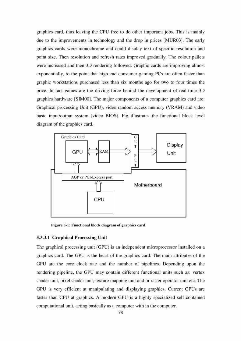
78
graphics card, thus leaving the CPU free to do other important jobs. This is mainly
due to the improvements in technology and the drop in prices [MUR03]. The early
graphics cards were monochrome and could display text of specific resolution and
point size. Then resolution and refresh rates improved gradually. The colour pallets
were increased and then 3D rendering followed. Graphic cards are improving almost
exponentially, to the point that high-end consumer gaming PCs are often faster than
graphic workstations purchased less than six months ago for two to four times the
price. In fact games are the driving force behind the development of real-time 3D
graphics hardware [SIM00]. The major components of a computer graphics card are:
Graphical processing Unit (GPU), video random access memory (VRAM) and video
basic input/output system (video BIOS). Fig illustrates the functional block level
diagram of the graphics card.
Figure �5-1: Functional block diagram of graphics card
5.3.3.1 Graphical Processing Unit
The graphical processing unit (GPU) is an independent microprocessor installed on a
graphics card. The GPU is the heart of the graphics card. The main attributes of the
GPU are the core clock rate and the number of pipelines. Depending upon the
rendering pipeline, the GPU may contain different functional units such as: vertex
shader unit, pixel shader unit, texture mapping unit and or raster operator unit etc. The
GPU is very efficient at manipulating and displaying graphics. Current GPUs are
faster than CPU at graphics. A modern GPU is a highly specialized self contained
computational unit, acting basically as a computer with in the computer.
Motherboard
AGP or PCI-Express port
CPU
GPU
Display
Unit RAM
OUT PUT
Graphics Card

79
5.3.3.2 Video RAM
The GPU has its own independent memory installed on the graphics card called Video
RAM (VRAM). It is independent of the RAM of the motherboard. The VRAM works
hand in hand with the GPU to help in bandwidth-intensive applications such as 3D
games. The typical VRAM sizes are 128, 256 and 512 MB.
5.3.3.3 Video BIOS
The video basic input/output system (Video BIOS) interfaces the GPU to the
motherboard and the display system. The GPU is connected to the CPU through the
accelerated graphics port (AGP) or the PCI-Express interface (peripheral component
interconnected express). The output images are exported to video display unit
(monitor). The typical output ports are the D-sub type VGA, composite video,
component video, digital video interface (DVI), or s-video etc. For analogue displays
the random access memory digital-to-analogue converter (RAMDAC) is used which
converts the digital signals into analogue signals. However, due to the growing
availability of digital computer displays, the RAMDAC is slowly disappearing from
the graphics card.
5.3.4 Integrated Graphics Processor
The “integrated graphics” processor allows a computer to perform video graphics
functions without a separate graphics card. It is a build-in graphics processor on the
motherboard. The overall cost of the integrated solution is much less than the discrete
graphic card solutions and also has lower power consumptions. Thus are commonly
used in laptop computers or some low- and mid-range desktops. Intel® “Extreme
Graphics II”, Intel graphics media accelerator (GMA) series such as GMA-900 and
GMA-X3500 are few examples of the integrated graphics solutions [INT07]. The
integrated graphics processor shares the computer main memory with CPU on same
bus, which imposes a performance penalty. They usually have inferior 3D
performance compared with dedicated graphics cards. Although, they are suitable for
most applications, but they are not usually a good choice for the gaming enthusiast or
professional applications [INT07].

80
5.3.5 Graphics Hardware Manufacturers
Major chip producers are ATI Technologies® and Nvidia® Corporation. Nvidia® is a
chipmaker only, focusing its attention solely on designing and producing graphics
processors while leaving the production and sale of retail cards to its board partners.
ATI® on the other hand, makes their own cards and is quite active in the retail market
as well. Nowadays, a PC-based graphic card has outperformed the thousand-pound
“high-end” graphics workstations of several years ago. Few examples of the graphics
cards from Nvidia® are the GeForce3 Ti 500GPU, GeForce4 Ti 4600GPU,
GeForceFX series, GeForce6 series and now the latest GeForce7 series. ATI®
Radeon® X1950 is the latest ATI product and can sample more textures per pass than
the GeForceTM latest card. Other than these, the Parhelia and P-series of Matrox® and
Wildcat of 3DLabs® are famous in the market place [SCO01]. GeForce3 (Nvidia) and
Radeon 8500 (ATI) replace fixed-function vertex and fragment (including texture)
stages with programmable stages. Minor chipset producers are S3 Graphics (Chrome
Series) XGI Tech Inc (Volari) and Tech Support (Rapton). The market leader in
graphics solutions are the Intel®, ATI® and Nvidia®. The VIA tech, SiS, Matrox
Graphics, XSI and 3Dlabs also have their products in market.
5.3.5.1 Nvidia® GeForceTM
GeForceTM is the Nvidia® GPU series for the main stream desktop PC user. It is the
most feature-rich cost effective and highly integrated GPU. The first GeForceTM was
GeForce 256 and was launched in August 1999. It was designed and marketed for the
gaming community of personal computer users. The latest in the GeForce series is the
GeForce® 7950 GX2 launched in June, 2006. It is 48 pixel pipeline PCI Express® chip
and also has SLI™ (Scalable link Interface) support for linking two video cards
together to produce a better output. Nvidia nForce® is the chipset for AMD Athlon®
and Duron® microprocessors and Nvidia Quadro® Plex is a professional workstation
class GPU used for computer aided design (CAD) and digital content creator (DCC)
applications. Nvidia Gelato® is rendering software designed to create stunning images
for applications in film and broadcast.
5.3.6 AGP and PCI Express
This started with the industry standard architecture (ISA) bus, then in the early 90’s
the era of the peripheral computer interconnection (PCI) came with 132 MB/sec

81
bandwidth. In the mid 90’s the accelerated graphics port (AGP) was developed
specifically for graphic cards. It was 32 bits which offered a bandwidth of 533
MB/sec in its initial version of AGP 2X and subsequently the AGP 4X and finally
AGP 8X was the latest version with a bandwidth of 2.133 GB/sec. Recently PCI-
Express, formally known as 3rd Generation Input Output (3GIO), has been developed
by Intel® Corporation. PCI-Express is a 32-bits local bus with bandwidth of 2.5
GB/sec. It is a two way serial connection. Where 3D performance is concerned, PCI-
Express offers at best minimal advantages over AGP. PCI uses a parallel connection
and shared bus protocol. AGP uses serial connection and point-to-point protocol. PCI-
Express also uses a serial connection and point-to-point protocol. It is general purpose
and has dual-channels. PCI express is two time faster than AGP 8X.
5.3.7 Nvidia® SLI Technology
In 2004, scalable link interface (SLI) technology was introduced by Nvidia. SLI
technology is a revolutionary approach to scalability and increased performance. SLI
can deliver as much as two times the performance of a single GPU. It combines two
graphics cards in a single system and doubles the graphics performance [NVI06].
Nvidia SLI can output in both digital and analogue formats for the highest image
quality. It needs a PCI Express motherboard and Nvidia based PCI Express graphics
cards, joined by the Nvidia SLI connector. It takes advantage of the increased
bandwidth of the PCI Express to automatically accelerate applications through a
combination of intelligent hardware and software solutions.
5.4 Graphics APIs
The application programming interface (API) is either the set of instructions written to
interface two programmes and make the job of the programmer bit easier, or it is a
software interface to the graphics hardware. The two main standard 3D APIs for real-
time graphics programming are Direct3D® from Microsoft® and OpenGL® (a standard
originally based on SGI’s GL API) [MUR03].
5.4.1 OpenGL®
In 1992, OpenGL® was introduced by Silicon Graphics Incorporated (SGI). It became
industry’s most widely used and supported 3D and 2D graphics API. With more than
sixty hardware developer licences, it is considered the mother of all APIs and is a

82
premier environment for developing portable interactive 2D and 3D graphics
applications. OpenGL® is supported on all the major computer platforms including;
AIX®, HP-UX®, IRIX®, Linux®, Mac®, OS X®, Microsoft® Windows® 2000,
Windows® XP and Solaris™. The top manufacturers of real-time 3D graphics cards;
3DLabs, ATI and NVIDIA have released products supporting the OpenGL 2.0
specifications and OpenGL Shading Language. OpenGL 2.0 is the latest core revision
of the OpenGL graphics software. Its specifications were finalized in September 2004
by the ARB (architecture review board), however, it was introduced in 2003. OpenGL
2.0 API represents a revolution in graphics by providing high-level access to the
programmable features of modern GPUs. It can create photo-realistic real-time 3D
graphics. OpenGL 2.0 is a direct compiled model, which means that a given graphics
hardware/driver combination will take its OpenGL source code and compile it directly
into machine code that runs on the graphics hardware. OpenGL is backward
compatible and is fully universally licensed throughout the graphic hardware
developers’ community. OpenGL is constantly evolving state-of-the-art functionality
to efficiently support a wide array of applications from consumer games to
professional design applications. OpenGL provides high-level access to the
programmable features of modern graphics processors. It creates photo-realistic, real-
time 3D graphics.
5.4.2 Architecture Review Board
The OpenGL architecture review board (ARB) is an industrial consortium that
governs the specifications of OpenGL®. It was formed in 1992. The nine promoting
members of the board are; 3DLabs, Apple, ATI, Dell Inc., IBM Corporation, Inter
Corporation, Nvidia Corporation, Sun Microsystems Inc., and SGI.
5.4.3 Difference between Direct3D and OpenGL
Direct3D® and OpenGL® are both graphical API packages used extensively in many
graphical systems. The Direct3D® is a proprietary standard API and includes a
software renderer and a hardware abstraction layer for accelerated rendering. It is
designed by the Microsoft® Corporation for hardware 3D acceleration on their
Windows® platforms and X-Box® family of video game consoles. Every time more
hardware features are added, a new version of Direct3D is released. The latest version
is DirectX 9.0c. On the other hand, OpenGL® is an open standard API available on

83
Windows®, Unix®, Apple Macintosh® and other platforms. It is independent of the
platform.
5.5 Realism
Realism is required for simulation, entertainment, advertising, research, education and
command and control applications. Ideally, the simulation would require interaction
between all of the photons and atoms in a scene, to correctly and accurately represent
real life phenomenon. However, it is not currently possible to perform this level of
simulation [FER01]. Therefore, to approximate these phenomena a variety of tricks or
special effects are used and with the advancements in computer graphics technologies,
the demand for realism is also increasing. Ideally, a system must produce an image as
accurately as possible (photo-realistic) and also as quickly as possible (at least 25
images/sec for movie-realistic) but accomplishing both of these goals at the same time
is a big challenge. The aim of any realistic imaging simulation is to produce images
that capture the appearance of real objects and scenes. Generating visually realistic
images are an art form and not a science because physical accuracy is not necessary to
produce visually realistic images. The following are the different types of realism.
5.5.1 Physical Realism
In physical realism, the image has to be an accurate point-by-point representation of
the spectral radiance values in a scene [FER01]. Physics based rendering algorithms
can create an accurate simulation of light travelling from the objects to the viewer. It
can be of great use in engineering and design applications. However, for human
consumption physically accurate rendering is usually an excess as it is beyond the
human visual processing limits. Also, it is extremely computationally expensive and it
is difficult to display the results as its dynamic range usually exceeds the capabilities
of the existing display devices [FER01].
5.5.2 Photo Realism
Photo realism means generating an image that is indistinguishable from a photograph
of a scene. The aim is to produce an image that appears the same as the photograph,
even if the physical energy coming off the image is different form the actual scene.
Although, photo-realistic rendering algorithms can be faster than physically realistic
algorithms, it is still computationally expensive [FER01].

84
5.5.3 Functional Realism
To overcome the issues of physical realism and photo realism, an approach is needed
to produce images which can allow an operator, for example, to do the required task
as efficiently as they would have done in the real world [FER01]. Functional realism
uses wide range of rendering styles depending upon its need. One example is the
rendering techniques used in flight simulators. In this application images are not
physically accurate nor are they photorealistic but they are functionally realistic
because they provide the user with much of the same visual information they would
get if they were flying a real plane [FER01].
5.6 Computer Graphics Rendering
Computer graphics is the art of creating realistic images on the computer and
rendering is the last step in the 3D computer graphics pipeline. It gives the final
appearance to the models and animation. Rendering is the process of converting three-
dimensional geometric descriptions of graphical objects into two-dimensional images.
Rendering could be photorealistic or non-photorealistic. The photorealistic rendering
is based on photo-realism and the real world. Whereas, the non-photorealistic
rendering is usually based on artistic paintings or drawings.
5.6.1 Rendering Pipeline Stages
Every rendering method has its own steps. However, the following are the stages
which are usually common in all rendering pipelines:
(a) Object Models Generation. All objects 3D models are generated in
local space and then transformed in to the world space with respect to other
objects present in the world space.
(b) Viewing Specifications. Depending upon the viewer angle or eye
space, the 3D scene is projected onto a 2D plane.
(c) Lighting Conditions. Calculating shading information based on the
position of lights in the environment and the surface properties.
(d) Hidden Surface Removal. The polygons or parts of the polygon not
visible in viewing or eye space are clipped. Also parts of objects that are too
close or too far away are also removed or clipped.

85
(e) Fragment Rasterization. The next step is converting scene into 2D
raster image (pixels or dots) for out put on a video display.
(f) Texturing and Colouring. Texturing is the association of one or more
images to a polygon and then colours are assigned to the visible surfaces.
(g) Anti-aliasing. Anti-aliasing reduces undesirable visual artefacts due to
insufficient sampling of textures or shades and motion blur.
(h) Animation. Time varying changes if motion is desired.
5.6.2 Types of Rendering
Many rendering algorithms have been researched and system used for rendering may
employ a number of different techniques to obtain a final image. The rendering
engines are either real-time or non-real time engines. Scan-line rendering, ray casting,
radiosity and ray tracing are the main techniques.
5.6.2.1 Scan-line Rendering
A scan-line rendering engine draws an imaginary line from the viewer’s eye through a
single pixel on the screen and into the imaginary 3D scene to determine what
elements would be visible. It scans one by one all pixels in the view window and
colours them accordingly.
5.6.2.2 Ray Casting
Ray casting is primarily used for real-time simulations. It cast a ray from the object to
the point of view and the angle of incidence of the light rays from the source(s) of
light to the view point. Based on the intensities the value of each pixel in the scene is
calculated.
5.6.2.3 Ray Tracing
Ray tracing is an extension of the same technique developed in scan-line rendering
and ray casting. In ray tracing the samples are imaginary rays traced backward from
each pixel on the monitor into the three dimensional model, thus considering only the
light that enters the eye. In ray tracing the angles of reflection and refraction are
calculated every time light hits any object. It is primarily beneficial when complex
and accurate rendering of shadows, refraction or reflection are issues.

86
5.6.2.3.1 Advantages and Disadvantages of Ray Tracing
Ray tracing is a very versatile technique. It can cover characteristics of direct
illumination, shadows, specular reflections and refractions through transparent objects
accurately. The ray tracing technique is computationally expensive and slow even for
scenes with only moderate complexity. Ray tracing does not cover diffuse inter-
reflections (diffraction and scattering), therefore, only the objects that are illuminated
directly are rendered accurately and areas or objects not directly illuminated are pitch
dark, which is clearly not the same as in the real world. Ray tracing cannot reproduce
secondary illumination effects from diffuse surfaces and tends to simulate light
reflecting only once off each diffuse surface. The ray tracing scene must be lit by
some light source for it to be visible. As it does not cover secondary illumination, the
phenomenon of IR radiation can not be shown with the help of the ray tracing.
5.6.2.4 Radiosity
Radiosity in computer graphics was first introduced in 1984; however, in the 60’s
methods for simulating the radiation heat transfer was developed by thermal
engineers. They modelled the emission and reflection of radiation and produce more
accurate inter object reflections. This produced a model for conservation of thermal
energy in a closed environment. Radiosity is the rate at which energy leaves a surface.
It is the sum of the rates at which the energy reflects or transmits from that surface or
other surfaces. All energy emitted or reflected by every surface is accounted for by its
reflection from or absorption by other surfaces. Unlike ray tracing which is a direct
illumination algorithm, radiosity is a global illumination algorithm. In radiosity any
light that hits a surface is reflected back into the same medium. This means any light
source as well as other objects acting as secondary illumination sources. Radiosity is
closer to nature and represent a scene more realistically as compared to ray tracing;
however, it deals with only diffuse or dull surfaces.
5.6.2.4.1 Advantages and Disadvantages of Radiosity
Radiosity is very realistic for diffuse surfaces. It is simple and easy to implement but
cannot handle point sources or specular reflections from shiny surfaces. It is
computationally expensive and slow. Radiosity operates on finite areas called patches.

87
5.6.3 Illumination Techniques
The physical material properties of the surface and the light conditions will determine
the colour or appearance of any specific pixel in any image. The local or global
illuminations are used to determine how a surface reflects and transmits light.
5.6.3.1 Local or Direct Illumination
Local illumination is that in which only the light coming directly from the light source
themselves is considered in the shading. It predicts the intensity, spectral
characteristics, colour and distribution of light.
5.6.3.2 Global Illumination
Global illumination not only considers the light directly coming from the source but
also reflections and refractions from other surfaces and objects present in the scene.
When light hits a surface, depending upon the material of the surface, part of it is
absorbed in the material and the rest is scattered out into the same environment. A
rough surface tends to reflect light back in all directions, called diffused reflection. On
the other hand a very smooth surface (like a mirror) reflects light in one direction and
this is called specular reflection.
5.6.3.3 Direct vs. Global Illumination
The direct illumination is that which consider the light falling on a surface only due to
the light that has taken a path directly from a light source. Whereas, global
illumination consider both direct as well as indirect illumination due to the reflections
of the light from other objects. Direct illumination can render both mathematically
derived objects and polygons. It can be modified to render soft shadows but it is very
tricky. The ray tracing is slow. Direct illumination is suitable for cases with point light
sources and perfectly shining objects. However, in the real world it is difficult to have
all things shining. On the other hand, global illumination techniques simulate multiple
reflections of light around a scene. In global illumination a scene may be lit simply by
its surroundings even without a light source present in the scene.
5.7 Virtual Reality Modelling Language
Virtual reality modelling language (VRML) is an open and flexible platform for
creating interactive three-dimensional (3D) scenes or virtual worlds. VRML is easy to

88
use as it is a text based object-oriented programming language written in World Wide
Web (WWW) oriented format. It uses file extensions such as “wrl”, “wrz” and
“wrl.gz” etc. In 1994, during a European web conference, Tim Berners Lee used the
term “virtual reality makeup language” when he emphasised the need for a 3D World
Wide Web standard. In the same year, a group of artists and engineers produced the
VRML-1 specifications which were based on a subset of the Open InventorTM file
format of Silicon Graphics Institute (SGI®). They also changed the name to virtual
reality modelling language (VRML). This first version of VRML could only create
static worlds. It was replaced with VRML-2 with animation features added. In 1997,
VRML-2 was adopted by the International Standard Organization (ISO) and was
referred as VRML97. Although, X3d is the successor of VRML97, (with added
features of humanoid animation, non-uniform rational B-splines (NURBS) and
geographical reference VRML etc.) still VRML97 is the current and functionally
complete version of VRML that is still popular with education and research oriented
applications.
VRML can specify objects and backgrounds with vertexes and edges of
polygons with surface colour, texture, shininess, transparency and many more
physical properties applied on it.
5.7.1 Military Vehicles 3D Virtual Reality Models
Due to the vast 3D modelling community, there are several sites available on the
internet which offer free downloads of 3D models of military vehicles in VRML
format. Even if the models are available in some other modelling formats, they can
easily be translated into VRML format using translation software. Table �5-1 shows a
list of a few such sites which provide 3D virtual models of military vehicles and other
objects required to develop a scene.

89
Table �5-1 : Virtual Reality Models available on the internet
Organization WWW Address
OCR Incorporated http://www.ocnus.com/models/Military/
3D World Club http://www.3dworldclub.com/browse.aspx
3D Caffe™ http://www.3dcafe.com/index.php
Amazing 3D Graphics http://www.amazing3d.com/services/aircraft1.html
CSC Modelling and Simulation
Centre of Excellence
http://www.cscmodeling.com/homepage.htm
Yaap Hanger VRML Models http://www.topedge.com/panels/aircraft/hangar/yaaphavr.html
Global Security.org http://www.globalsecurity.org/military/systems/aircraft/index.html
Federation of American Scientists http://www.fas.org/man/dod-101/sys/ac/index.html
Free models index http://www.amazing3d.com/modfree.shtml
5.7.2 Open InventorTM vs VRML
Open InventorTM is an object oriented 3D graphical library written in C++
programming language. It is built on top of OpenGL® and provides a high-level
interface to OpenGL®. Open InventorTM is developed and maintained by Silicon
Graphics Institute (SGI®). Open InventorTM and VRML are quite similar. Open
InventorTM has node classes that exactly match the node definition in the VRML
specifications. The VRML specifications were written on the bases of Open
InventorTM. Many new features were added in VRML which were not available in
Open InventorTM. Later on, these additional features developed in VRML were also
available in Open InventorTM latest version 6.0. Open InventorTM includes a rich set of
objects such as cubes, polygons, texts, materials, camera and lights etc. It has a built
in viewer and editor for editing virtual worlds [JAN03].
5.8 Virtual Reality Toolbox
Virtual reality (VR) toolbox is a software package developed by “The MathWorks
Institute”, for use with MATLAB® and Simulink® [VIR04]. It provides a solution for
interacting with virtual reality models of dynamic systems in engineering
applications. VR-toolbox enables the programmers to create virtual worlds or 3D
scenes and animate them in the Simulink® environment. Using VR-toolbox, a
developer can interact with the virtual world and change the position and other
properties of objects while running the simulation. To enable programmers to model

90
or develop virtual worlds and to view their results, the VR-toolbox contains a VRML
editor or builder and VRML viewer.
5.8.1 V-Realm™ Builder/Editor
The V-Realm™ is a virtual reality builder/editor programme developed by Ligos
Corporation, USA. It is part of the VR-toolbox of The MathWorks Institute [VIR04].
The V-Realm™ is used to create complex shapes and landscapes for virtual worlds. It
helps in applying material properties, texture-mapping and animations on the virtual
worlds. In V-realm™ builder the user can create and edit the VR worlds in VRML97
code. It is a much faster way of editing and takes away the time consuming hand
coding process. It is graphical user interface (GUI) based editor in which the user can
quickly alter existing nodes and fields or add more nodes while viewing the results
instantaneously. It has a cut-copy-paste edit facility which makes the job of editing
very easy and fast. V-realm builder contains objects, textures, transforms and material
libraries which can easily be called at any time. It can import Open Inventor, VRML-
1.0, 3D studio, SGI wave-front and true space files.
5.8.2 Virtual Reality Viewer
VR-toolbox contains a virtual reality viewer (VR-viewer) that enables the developers
to visualize the virtual worlds. Alternatively, on a PC platform, the results of a virtual
world can be viewed on VRML enabled internet browsers using TCP/IP protocol
[VIR04]. The VR-viewer provided with VR-toolbox is a Windows based viewer with
a menu bar and toolbar and navigation panel for moving and rotating the objects. It
also has a feature for capturing the static virtual scenes and recording the animations.
5.8.3 MATLAB VRML Interface
The VR toolbox provides an interface between MATLAB and virtual reality. To
interact with the virtual world from MATLAB, it associates all transform and rotation
and material properties with MATLAB source code. In VRML the world coordinates
systems are used. It is a right hand Cartesian coordinates system with positive Y-axis
pointing up and positive Z-axis coming out of the screen towards the viewer. It differs
from MATLAB coordinates which takes positive Z-axis as upward and negative
Y-axis out of the screen. Figure �5-2 explains both VRML and MATLAB coordinate
systems. To translate VRML coordinates to MATLAB, it has to be rotated 90o

91
clockwise on the X-axis [NIE00]. The units used in VRML and MATLAB are meters
for the dimensions and radians for the angles. To interact with nodes and fields of the
virtual world from the MATLAB environment, it is necessary to give unique names to
all nodes in the virtual world.
Figure �5-2 : MATLAB VRML Coordinates System
5.9 MATLAB® Aerospace Blockset
Aerospace Blockset is a Simulink® block set of MATLAB® which comprises of
aerospace system design, integration and aircraft simulations. It consists of a variety
of core components to assemble a broad aerospace system. Its library contains the
environmental models, 6-DOF motion equation models, 3-DOF motion equations
model, aerodynamic model, flight trajectories, propulsion and actuator models. It also
has utilities such as Direction Cosine matrix, Euler angles, quaternion and also the
unit conversion functions. The Aerospace Blockset can be used with Real-Time
Workshop® to generate code for the real-time execution of programmes for
prototyping and hardware-in-the-loop (HWIL) applications.
5.10 Microsoft Flight Simulator
Microsoft Flight Simulator® is a video game developed by Microsoft® Corporation for
their Windows® platform. It is one of the best known and most comprehensive flight
simulators in the video game category. It started in 1982 as a simple small aircraft
simulator and now it uses 3D graphics and graphics hardware acceleration to present
state-of-the-art results. The latest version is Flight Simulator-X, released in late 2006.
X-axis X-axis
Y-axis
Y-axis
Z-axis
Z-axis
VRML MATLAB

92
It can simulate the flights over any area and environment around whole world in all
weather conditions. It includes over 20,000 airports and has a vast library of airplanes
from Wright Brothers 1903 Flyer to latest Boeing-777s.
5.11 Unmanned Dynamics AeroSim Blockset
AeroSim blockset is a MATLAB®/Simulink® block library for developing aircraft
dynamic models with visualization interfaces to Microsoft Flight Simulator®,
FlightGear and other products. It was designed by flight control engineers at
Unmanned Dynamics, LLC. It includes equations of motion, aerodynamics and
propulsion models. It also contains an environmental model such as the atmosphere,
wind, turbulence and gravity. It also provides transformation to and from various
references. The AeroSim blocksets are built in C-code using simulation block
components. It can be used for real-time HWIL simulation applications by generating
C-code using Real-Time Workshop®. AeroSim can work on Windows® platforms
with MATLAB® and Simulink® installed.
5.12 FlightGear Flight Simulator
FlightGear is an open source free flight simulator project available under general
public licence. It is a unique project developed by the public, for the public and
maintained and upgraded by the public. Anyone can contribute towards expansion and
improvements of the code. It is a sophisticated flight simulator frame work for use in
a research and an academic environment. The idea of FlightGear came from the
problem that commercial PC based flight simulators are proprietary and do not give
access to their source code for modification and enhancement. The FlightGear source
code is available and can be altered by any person having sufficient understanding of
programming. Many people involved in research and education could use the
FlightGear frame work on which they can built their own project. FlightGear can run
on Windows®, linux®, Mac OS-X®, Solaris® and IRIX® platforms. FlightGear
contains a flight dynamic model and an extensive and accurate world scenery
database of over 20,000 real world airports. It also contains an accurate and detailed
sky model. It contains a flexible and open aircraft modelling system in which the
programmer can model a wide variety of aircraft. FlightGear does not require a
sophisticated computer. It can work smoothly on a moderate PC with a reasonable

93
hardware accelerated 3D card with full OpenGL drivers. On a 1 GHz class CPU, with
a GeForce graphics card, frame rates in excess of 60 frames per second are possible.
5.13 Conclusion
Driven by the steadily growing demands of the gaming industry, the performance of
modern graphics processors has exceeded the computational power of CPUs both in
raw numbers and in their extraordinary rate of growth. Today's GPUs have evolved
into very sophisticated, highly programmable processing units. Programmability of
consumer level graphics hardware has evolved at an increasing pace. In past many
low cost PC based military simulators has been developed which uses COTS
software.
Although, Nvidia GeForce and ATI Radon provides the best low- and mid-
range hardware graphics solutions in the market. However, in this work, the Intel
“Extreme Graphic II” integrated graphics processor has been used to keep the cost as
low as possible and as well as get sufficient processing power to render scenes using
MATLAB VR Toolbox.
VRML and Open InventorTM are the two most widely used programmes for
3D virtual reality modelling. It is mainly because of the free graphical resources
available from BlaxxunTM Interactive Institute and Silicon Graphics Institute SGI®
[DUT04]. As MATLAB VR Toolbox uses VRML for virtual modelling thus in this
work VRML has been used for developing 3D virtual world for IR signature
modelling and simulation. An effort has been made to achieve functional realism
using low cost hardware graphics and COTS software. The details of developing 3D
virtual IR scene are given in Chapter-7 and 8.


![La crisis de los misiles[1]](https://img.pdfslide.net/doc/110x75/558bae8ad8b42a71408b459b/la-crisis-de-los-misiles1.jpg)