Embed Size (px)
Citation preview
Machine Copy for Proofreading, Vol. x, y–z, 2014
Carbon Fiber Reinforced Polymer with Isotropic 60 GHz Reflectivity
Erich Zochmann*,1,2, Gerald Artner2, Stefan Pratschner1,2, Martin Lerch2,Christoph F. Mecklenbrauker2 and Markus Rupp2
Abstract—Carbon fiber reinforced polymer (CFRP) are measured as reflector material for millimeterwaves at 60 GHz. Reflectivity is measured to characterize material anisotropy in a mono-static setup.Disc shaped material samples are rotated in steps of one degree. Four commonly employed CFRP areinvestigated: unidirectional fibers, plain-weave, twill-weave and fiber shreds. Results show that theunidirectional CFRP and twill-weave CFRP are anisotropic, while the remaining materials are isotropicwithin measurement accuracy.
1. INTRODUCTION
Carbon fiber reinforced polymer (CFRP) consist of a polymer matrix that is reinforced with carbonfibers. Antennas are built from CFRP [1, 2], but more commonly large CFRP parts are applied asantenna ground planes [3–7], reflectors [8] or panels for slot antennas [9–11]. Airplanes, boats, carchassis and sports equipment are today built with CFRP. There, CFRP are widely utilized in lightweightconstruction, where they are built as laminates. From a mechanical engineering viewpoint CFRPlaminates with unidirectional (UD) fiber and ply alignment offer a large Young’s modulus relative tomaterial density, but they are orthotropic and high material strength is only obtained in fiber direction.Woven fabrics are used to get more smoothed mechanical and electrical properties, but Young’s modulusis then greatly reduced. Plain-weave and twill-weave CFRP are among these fabrics. Plain-weave CFRPare widely applied in large laminate panels, but suffer from a poor drapability. Therefore, twill-weavesare often applied in parts with more complex shapes. CFRP with fiber-shreds are typically built withcompression molding and spray-up techniques. They are often brought in when the application ofrecycled fibers is beneficial.
1.1. Related and prior work
Measurements of anisotropic conductivity of UD-CFRP of up to 12 GHz are found in [12,13]. Those oftwill-weave CFRP and shred-CFRP are found in [14]. In most practical applications isotropic materials,which have little influence on reflectivity and antenna patterns are preferred. Only, in specializedapplications the anisotropy of CFRP can be utilized, e.g., as mode filters for reconfigurable antennas [15]or as polarization filtering reflectors [16]. Measurements of UD-, twill- and shred- CFRP as ground planematerials for monopole antennas show, that twill- and shred-CFRP behave as isotropic ground planesup to at least 10 GHz, while the UD-CFRP ground plane has a large influence on the antenna’s gainpattern and efficiency [5].
Millimeter waves are increasingly used for radar applications [17, 18] and for wirelesscommunications [19, 20]. Especially the 60 GHz band has attracted attention recently. The IEEE802.11ad standard is subject to investigation as possible vehicular communications standard [21] andfor joint radar-communications [22]. CFRP reflectors are applicable at millimeter wavelengths, as
15 February 2018* Corresponding author: Erich Zochmann ([email protected]).1 Christian Doppler Laboratory for Dependable Wireless Connectivity for the Society in Motion. 2 Institute of Telecommunications,TU Wien, Austria.
2 Zochmann et al.
demonstrated in [23], where a parabolic millimeter wave reflector is built from UD-CFRP as part ofan autonomous unmanned helicopter’s radar system [24]. The gain of the CFRP reflector antenna isfound to be close to that of a chrome plated version at 96 GHz [23]. Above 100 GHz the anisotropicreflectivity of UD-CFRP is measured in [25, 26], but material orientation is only considered in fiberdirection and perpendicular to fiber direction. Reflectivity measurements in two directions are sufficientto characterize UD-CFRP, but woven fabrics have a more complex geometry and therefore require afiner angular resolution. Mono-static reflectivity measurements are important for radar applicationsand antenna reflectors.
In many applications isotropic reflectivity is desirable. As is well known, UD-CFRP are unsuitabledue to their anisotropy. Woven materials are frequently used instead. Recently, it was shown thatthe application of the commonly used twill-weave CFRP is limited at millimeter waves, because thewavelength is then close to the size of their weave pattern, and grating effects possibly cause anisotropicreflectivity in bi-static setups [27]. It is therefore necessary to identify CFRP that have isotropicreflectivity at 60 GHz.
1.2. Contribution
The isotropy of four different CFRP laminates at 60 GHz is investigated. This closes the gap of CFRPinvestigation in the V- and E-band. Isotropy is determined by measuring the angle dependent relativereflectivity. All samples are cut to disc shapes and rotated in steps of one degree. Our material sampleshave unidirectional, plain-weave, twill-weave and shredded fibers ply geometries. We emphasize, thatmono-static reflectivity is measured in this work.
2. MATERIALS UNDER TEST
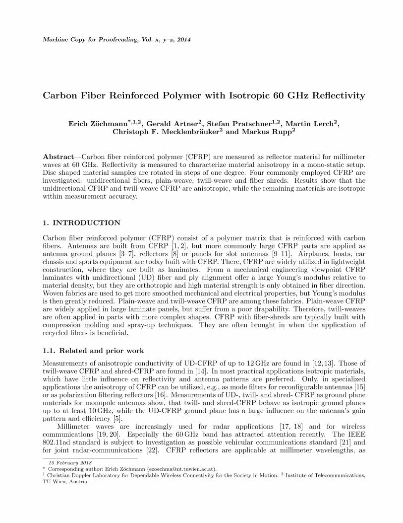
Four different CFRP laminates with different ply structures are investigated: unidirectional, plain-weave, twill-weave and fiber shreds. These materials are shown in Fig. 1 and are referred to as UD-CFRP,plain-CFRP, twill-CFRP and shred-CFRP, respectively. As reference, measurements are repeated withan aluminum sheet and an FR4 laminate with a copper layer. Aluminum without surface treatmentis used. The FR4 material is a Panasonic 104 laminate that is usually used for printed circuit boardproduction. Its copper plating has a thickness of 17µm. All materials under test (MUT) are cut todiscs of 280 mm diameter by water-jet.
The UD-CFRP has all fibers aligned towards ϕ = 0◦. The plain-CFRP has an elementary cell sizeof its characteristic checker-board pattern of about 2 × 2 mm2. The twill-CFRP is a 2/2 twill-weavewith a pattern size of about 2 × 4 mm2. The geometries of the plain- and twill-CFRP are within thesame order of magnitude as the free space wavelength of approximately 5 mm. The laminate’s pliesare stacked as [0 90]. For the plain- and twill-CFRP a zero direction ϕ = 0◦ is defined according toFigs. 1b–1c. The shred-CFRP has shredded fiber strands of about 10 mm length in random alignmenton its top layer. For shred-CFRP ϕ = 0◦ is arbitrarily defined. The UD-CFRP, plain-CFRP andtwill-CFRP are commercially available.
3. MEASUREMENT SETUP
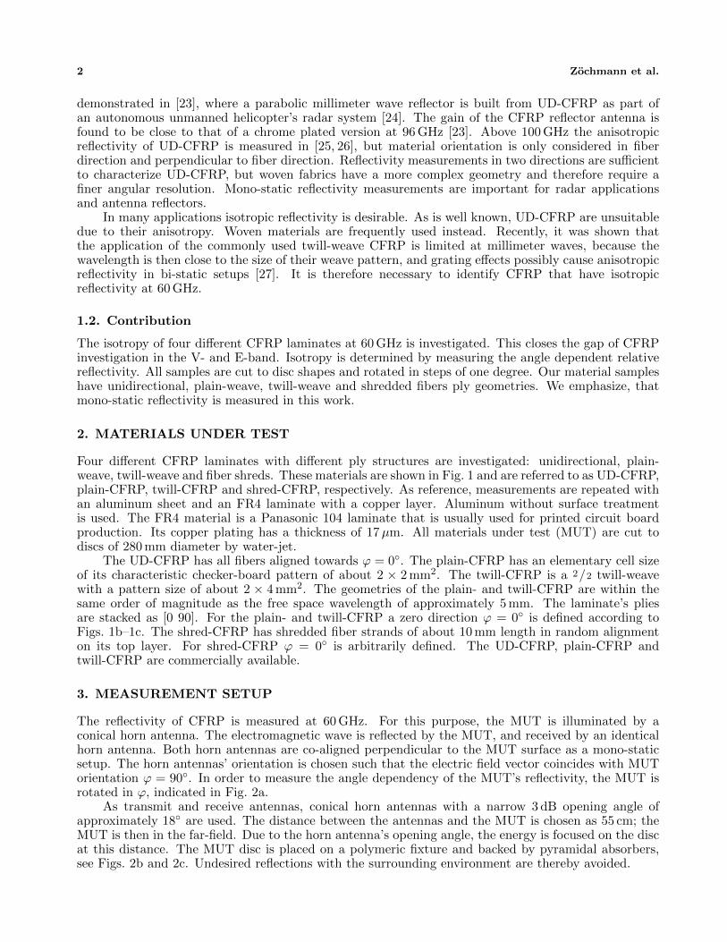
The reflectivity of CFRP is measured at 60 GHz. For this purpose, the MUT is illuminated by aconical horn antenna. The electromagnetic wave is reflected by the MUT, and received by an identicalhorn antenna. Both horn antennas are co-aligned perpendicular to the MUT surface as a mono-staticsetup. The horn antennas’ orientation is chosen such that the electric field vector coincides with MUTorientation ϕ = 90◦. In order to measure the angle dependency of the MUT’s reflectivity, the MUT isrotated in ϕ, indicated in Fig. 2a.
As transmit and receive antennas, conical horn antennas with a narrow 3 dB opening angle ofapproximately 18◦ are used. The distance between the antennas and the MUT is chosen as 55 cm; theMUT is then in the far-field. Due to the horn antenna’s opening angle, the energy is focused on the discat this distance. The MUT disc is placed on a polymeric fixture and backed by pyramidal absorbers,see Figs. 2b and 2c. Undesired reflections with the surrounding environment are thereby avoided.
CFRP with Isotropic 60 GHz Reflectivity 3
φ0°
(a)
2 mm
φ0°
2 mm
(b)
2 mm4 mm
φ0°
(c)
φ0°
(d)
Figure 1: Photographs of the investigated CFRP: a) unidirectional fiber alignment, b) plain weave, c)twill weave and d) fiber shreds in random alignment on top. All ruler dimensions are in centimeter.
The transmit signal is generated as shown Fig. 2a. An arbitrary waveform generator (KeysightM8195A) produces a 1 GHz wide baseband sequence. The baseband sequence is a low crest factor multi-tone signal with Newman phases [28]. This baseband signal is up-converted with an external module(Pasternack PEM001) that includes a synthesizer phase-locked loop (PLL) and uses a 285.714 MHzreference signal. The transmitted signal is centered at 7/4 ·120 ·285.714 MHz = 59999.94 MHz ≈ 60 GHz,where 7/4 · 120 is the scaling factor of the PLL counters.
A spectrum analyzer (R&S FSW67) is employed as receiver. It obtains and stores IQ samplesfrom the received signal. Multiple, consecutive received multi-tone signals, for fixed ϕ, are coherentlyaveraged to achieve a processing gain of 33 dB [28]. The receive power P (ϕ) is the sum power of alltones. The arbitrary waveform generator and the reference clock for the PLL are all synchronized tothe 10 MHz reference of the FSW67.
4. MEASUREMENT RESULTS
The transmit power is 7 dBm, which results in a received power of about −25 dBm depending on theused material. To allow comparison of all materials in one plot, the receive power is normalized to themean received power for each MUT, i.e., P (ϕ)/E {P (ϕ)}, where E{·} denotes the expectation operator.Losses in the MUTs are therefore not visible in the results. For measurements of losses in the compositeother methods are at hand, for example [25].
The normalized reflected power is shown in Fig. 3 as a function of MUT orientation. Reflectivityof the four investigated CFRP is shown together with the reflectivity of the aluminum and the FR4reference material. Two full rotations of the MUT discs are performed as an estimate for angularpositional precision; the second rotations are shown in lighter shades. The total measurement precisionis 0.6 dB, as described in Section 5.
4 Zochmann et al.
arbitrarywaveformgenerator
PLL
up-converter
285.714MHz
∼
spectrumanalyzer
MUT
ϕ
0 – 1GHz
59 – 61GHz
10MHzsync.
ref.
(a)
(b)
(c)
Figure 2: Schematic and photograph of the measurement setup. a) Schematic: The transmitter isbuilt with an arbitrary waveform generator as baseband signal generator and an external up-convertermodule. A spectrum analyzer is used as receiver. All units are synchronized. b) Photograph: Thetransmit horn antenna is aligned to the turning MUT disc, which reflects the wave back to an alignedreceive horn. The MUT disc is backed by absorbers. c) Close-up of polymeric disc fixture and rotationtable (top view).
CFRP with Isotropic 60 GHz Reflectivity 5
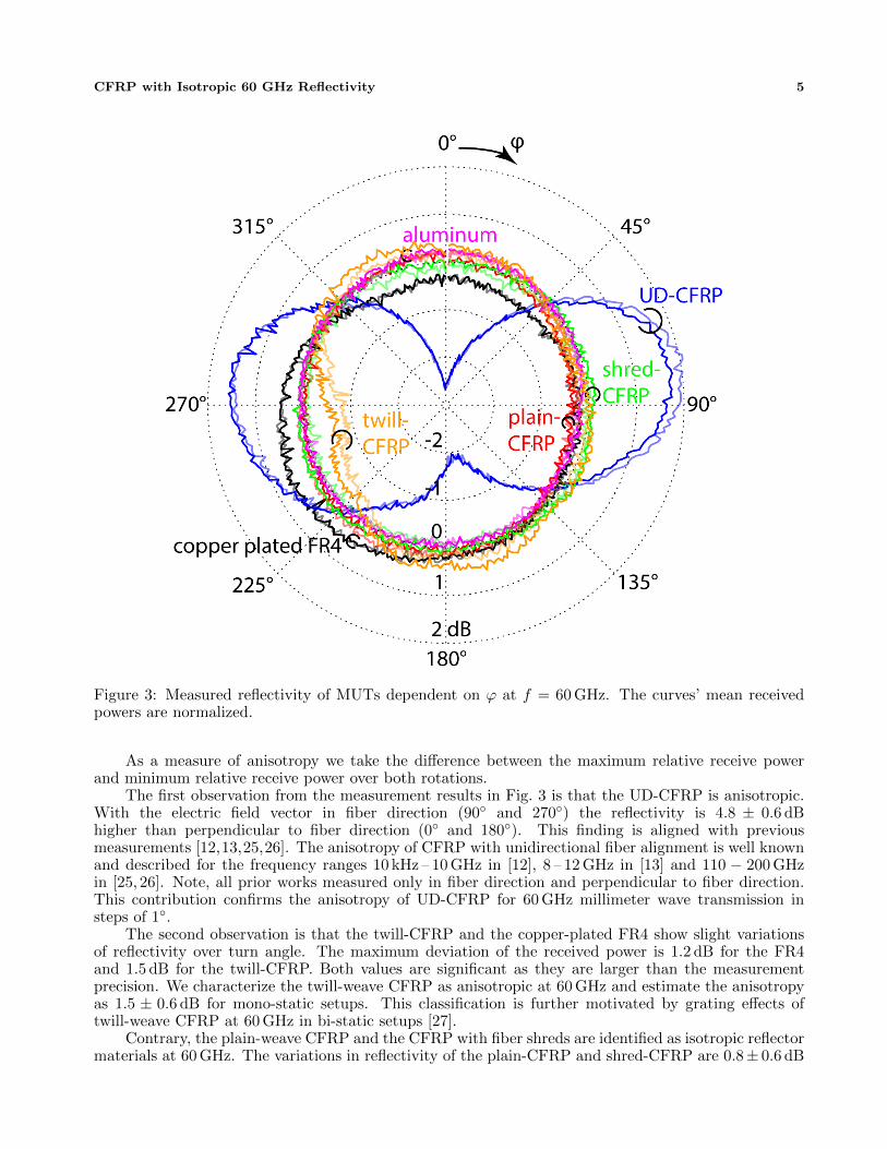
Figure 3: Measured reflectivity of MUTs dependent on ϕ at f = 60 GHz. The curves’ mean receivedpowers are normalized.
As a measure of anisotropy we take the difference between the maximum relative receive powerand minimum relative receive power over both rotations.
The first observation from the measurement results in Fig. 3 is that the UD-CFRP is anisotropic.With the electric field vector in fiber direction (90◦ and 270◦) the reflectivity is 4.8 ± 0.6 dBhigher than perpendicular to fiber direction (0◦ and 180◦). This finding is aligned with previousmeasurements [12,13,25,26]. The anisotropy of CFRP with unidirectional fiber alignment is well knownand described for the frequency ranges 10 kHz – 10 GHz in [12], 8 – 12 GHz in [13] and 110 − 200 GHzin [25, 26]. Note, all prior works measured only in fiber direction and perpendicular to fiber direction.This contribution confirms the anisotropy of UD-CFRP for 60 GHz millimeter wave transmission insteps of 1◦.
The second observation is that the twill-CFRP and the copper-plated FR4 show slight variationsof reflectivity over turn angle. The maximum deviation of the received power is 1.2 dB for the FR4and 1.5 dB for the twill-CFRP. Both values are significant as they are larger than the measurementprecision. We characterize the twill-weave CFRP as anisotropic at 60 GHz and estimate the anisotropyas 1.5 ± 0.6 dB for mono-static setups. This classification is further motivated by grating effects oftwill-weave CFRP at 60 GHz in bi-static setups [27].
Contrary, the plain-weave CFRP and the CFRP with fiber shreds are identified as isotropic reflectormaterials at 60 GHz. The variations in reflectivity of the plain-CFRP and shred-CFRP are 0.8± 0.6 dB
6 Zochmann et al.
0 500 1000 1500 2000 2500 3000 3500 4000 4500
22.5
2323
.524
tem
pera
ture
/ °C
measurement number
≈32 minutes
(a)
0 500 1000 1500 2000 2500 3000 3500 4000 4500
-0.2
00.
2
pow
er v
aria
tion
/ dB
measurement number(b)
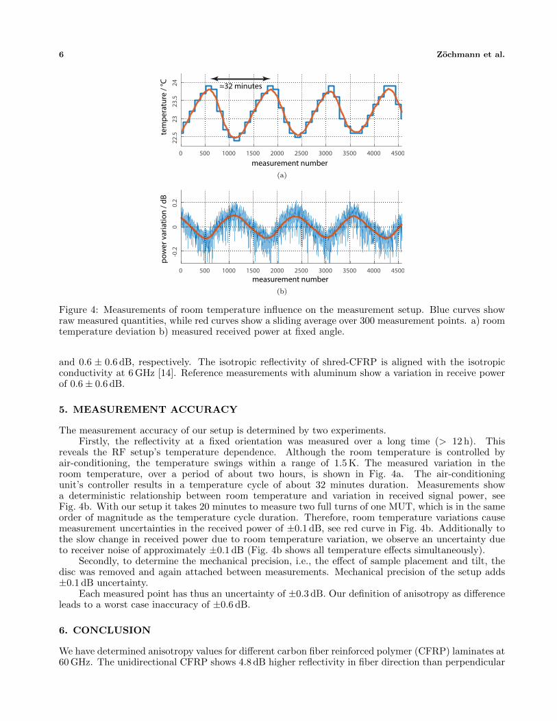
Figure 4: Measurements of room temperature influence on the measurement setup. Blue curves showraw measured quantities, while red curves show a sliding average over 300 measurement points. a) roomtemperature deviation b) measured received power at fixed angle.
and 0.6 ± 0.6 dB, respectively. The isotropic reflectivity of shred-CFRP is aligned with the isotropicconductivity at 6 GHz [14]. Reference measurements with aluminum show a variation in receive powerof 0.6± 0.6 dB.
5. MEASUREMENT ACCURACY
The measurement accuracy of our setup is determined by two experiments.Firstly, the reflectivity at a fixed orientation was measured over a long time (> 12 h). This
reveals the RF setup’s temperature dependence. Although the room temperature is controlled byair-conditioning, the temperature swings within a range of 1.5 K. The measured variation in theroom temperature, over a period of about two hours, is shown in Fig. 4a. The air-conditioningunit’s controller results in a temperature cycle of about 32 minutes duration. Measurements showa deterministic relationship between room temperature and variation in received signal power, seeFig. 4b. With our setup it takes 20 minutes to measure two full turns of one MUT, which is in the sameorder of magnitude as the temperature cycle duration. Therefore, room temperature variations causemeasurement uncertainties in the received power of ±0.1 dB, see red curve in Fig. 4b. Additionally tothe slow change in received power due to room temperature variation, we observe an uncertainty dueto receiver noise of approximately ±0.1 dB (Fig. 4b shows all temperature effects simultaneously).
Secondly, to determine the mechanical precision, i.e., the effect of sample placement and tilt, thedisc was removed and again attached between measurements. Mechanical precision of the setup adds±0.1 dB uncertainty.
Each measured point has thus an uncertainty of ±0.3 dB. Our definition of anisotropy as differenceleads to a worst case inaccuracy of ±0.6 dB.
6. CONCLUSION
We have determined anisotropy values for different carbon fiber reinforced polymer (CFRP) laminates at60 GHz. The unidirectional CFRP shows 4.8 dB higher reflectivity in fiber direction than perpendicular
CFRP with Isotropic 60 GHz Reflectivity 7
to the fibers. The anisotropy of twill-weave CFRP is 1.5 dB and twill-CFRP is classified to be anisotropicas well. Both, plain-weave CFRP and CFRP with about 10 mm long fiber shreds in random alignmenton the top layer, show isotropic reflectivity within measurement accuracy.
For most applications, such as antenna reflectors, isotropic reflectivity is desired. Among theinvestigated laminates, shred-CFRP and plain-weave CFRP are identified as suitable materials. Theperformed measurements highlight shred-CFRP as reflector material for millimeter wave applications.Shred-CFRP has both the least measured anisotropic reflectivity and the shredded fibers are obtainablefrom recycling [29].
The isotropic characteristics of CFRP for millimeter waves also motivate their application outsideof mechanical engineering for antenna applications and waveguides. Alignment of anisotropic CFRPcar parts influences the radar cross section for millimeter wave automotive radar.
ACKNOWLEDGMENT
The financial support by the Austrian Federal Ministry of Science, Research and Economy and theNational Foundation for Research, Technology and Development is gratefully acknowledged.
REFERENCES
1. S. M. Asif, et al., “On Using the Electrical Characteristics of Carbon Microfibers for Designinga Monopole Antenna,” in IEEE International Symposium on Antennas and Propagation (APS),2016, pp. 1881–1882.
2. L. Manac’h, X. Castel, and M. Himdi, “Performance of a Lozenge Monopole Antenna Made of PureComposite Laminate,” Progress in Electromagnetics Research Letters, vol. 35, 2012, pp. 115–123.
3. C. A. Balanis, and D. DeCarlo, “Monopole Antenna Patterns on Finite Size Composite GroundPlanes,” IEEE Transactions on Antennas and Propagation, vol. 30, no. 4, 1982, pp. 764–768.
4. G. Artner, and R. Langwieser, “Performance of an Automotive Antenna Module on a Carbon-Fiber Composite Car Roof,” in European Conference on Antennas and Propagation (EuCAP),Davos, Switzerland, 2016.
5. G. Artner, R. Langwieser, and C. F. Mecklenbrauker, “Carbon Fiber Reinforced Polymer asAntenna Ground Plane Material Up to 10 GHz,” in European Conference on Antennas andPropagation (EuCAP), Paris, France, 2017.
6. G. Artner, R. Langwieser, and C. F. Mecklenbrauker, “Concealed CFRP Vehicle Chassis AntennaCavity,” IEEE Antennas and Wireless Propagation Letters, vol. 16, 2017, pp. 1415–1418.
7. R. R. de Assis, and I. Bianchi, “Analysis of Microstrip Antennas on Carbon Fiber CompositeMaterial,” Journal of Microwaves, Optoelectronics and Electromagnetic Applications, vol. 11, no.1, 2012, pp. 154–161.
8. K. M. Keen, “Surface Efficiency Measurements on a High-Modulus Carbon Fibre CompositeReflector Antenna at L- and S-Band Frequencies,” Electronics Letters, vol. 12, no. 7, 1976, pp.160–161.
9. K. J. Nicholson, W. S. T. Rowe, P. J. Callus, and K. Ghorbani, “Split–Ring Resonator Loading forthe Slotted Waveguide Antenna Stiffened Structure,” IEEE Antennas and Wireless PropagationLetters, vol. 10, 2011, pp. 1524–1527.
10. A. Galehdar, et al., “Capacitively Fed Cavity-Backed Slot Antenna in Carbon-Fiber CompositePanels,” IEEE Antennas and Wireless Propagation Letters, vol. 11, 2012, pp. 1028–1031.
11. K. J. Nicholson, et al., “Coaxial Right/Left-Handed Transmission Line for Electronics BeamSteering in the Slotted Waveguide Antenna Stiffened Structure,” IEEE Transactions on MicrowaveTheory and Techniques, vol. 62, no. 4, 2014, pp. 773–778.
12. H. C. Kim and S. K. See, “Electrical properties of unidirectional carbon-epoxy composites in widefrequency band,” Journal of Physics D: Applied Physics, vol. 23, pp.916–921, 1990.
13. A. Galehdar, et al., “The effect of ply orientation on the performance of antennas in or on carbonfiber composites,” Progress In Electromagnetics Research, vol. 116, pp.123-136, 2011.
8 Zochmann et al.
14. G. Artner, P. K. Gentner, J. Nicolics, and C. F. Mecklenbrauker, “Carbon Fiber ReinforcedPolymer with Shredded Fibers: Quasi-Isotropic Material Properties and Antenna Performance,”International Journal of Antennas and Propagation, vol. 2017, Article ID 6152651, 2017.
15. A. Mehdipour, et al., “Mechanically reconfigurable antennas using an anisotropic carbon-fibrecomposite ground,” IET Microwaves, Antennas & Propagation, vol. 7, no. 13, pp. 1055-1063, 2013.
16. A. Galehdar, et al., “A frequency selective polarizer using carbon fibre reinforced polymercomposites,” Progress In Electromagnetics Research C, Vol. 25, 107-118, 2012.
17. M. Russell, et al., “Millimeter-wave radar sensor for automotive intelligent cruise control (ICC),”IEEE Transactions on Microwave Theory and Techniques, vol, 45, no. 12, pp. 2444–2453, 1997.
18. J. Hasch, et al., “Millimeter-wave technology for automotive radar sensors in the 77 GHz frequencyband,” IEEE Transactions on Microwave Theory and Techniques, vol. 60, no. 3, pp. 845–860, 2012.
19. Z. Pi, F. Khan, “An introduction to millimeter-wave mobile broadband systems,” IEEECommunications Magazine, vol. 49, no. 6, 2011.
20. W. Roh, et al., “Millimeter-wave beamforming as an enabling technology for 5G cellularcommunications: Theoretical feasibility and prototype results,” IEEE Communications Magazine,vol. 52, no. 2, pp. 106–113, 2014.
21. V. Va, T. Shimizu, G. Bansal, and R.W. Heath Jr, “Millimeter wave vehicular communications: Asurvey,” Foundations and Trends in Networking, vol. 10, no. 1, 1–113.
22. P. Kumari, et al., “IEEE 802.11 ad-based Radar: An Approach to Joint Vehicular Communication-Radar System,” in IEEE Transactions on Vehicular Technology, 2017
23. S. Futatsumori, et al., “Fundamental Applicability Evaluation of Carbon Fiber Reinforced PlasticMaterials Utilized in Millimeter-Wave Antennas,” in IEEE Conference on Antenna Measurementsand Applications (CAMA), 2014.
24. S. Futatsumori, A. Kohmura, and N. Yonemoto, “Performance Measurement of Compact and High-Range Resolution 76 GHz Millimeter-Wave Radar System for Autonomous Unmanned Helicopters,”IEICE Transactions on Electronics, vol. 96, no. 4, 2013, pp.586–594.
25. C. G. M. van’t Klooster, V. V. Parshin, and S. E. Mayasnikova, “Reflectivity of Antenna Reflectors:Measurements at Frequencies between 110 and 200 GHz,” in IEEE Antennas and PropagationSociety International Symposium (APS), 2003.
26. C. van’t Klooster, V. Parshin, “Reflector Reflection Loss 110–350 GHz,” in InternationalSymposium on Antennas and Propagation (ISAP), Niigata, Japan, 2007.
27. G. Artner, et al., “Angle-dependent reflectivity of twill-weave carbon fibre reinforced polymer formillimetre waves,” Electronics Letters, DOI: 10.1049/el.2017.3010
28. E. Zochmann, et al., “Associating Spatial Information to Directional Millimeter Wave ChannelMeasurements” in IEEE Vehicular Technology Conference (VTC-Fall), 2017.
29. F. Teodorescu, et al., “On the recycling of carbon fibers reinforced polymer matrix composites,” inIASME/WSEAS International Conference on Energy, Environment, Ecosystems and SustainableDevelopment, EEESD, 2008.