Embed Size (px)
Citation preview

S1
Supporting Information for:
Solvent-free organocatalytic preparation of cyclic organic carbonates under scalable continuous flow conditions
Zhiguo Wang,a,† Romaric Gérardy,a Guillaume Gauron,b Christian Damblonc and Jean-Christophe M. Monbaliua,*
a Center for Integrated Technology and Organic Synthesis, Research Unit MolSys, University of Liège, B-4000 Liège (Sart Tilman), Belgiumb Corning Reactor Technologies, Corning SAS, 7 bis, Avenue de Valvins CS 70156 Samois sur Seine, 77215 Avon Cedex, Francec CREMAN NMR Center, Research Unit MolSys, University of Liège, B-4000 Liège (Sart Tilman), Belgium†Current address: Hubei Key laboratory of Mine Environmental Pollution Control and Remediation, School of Chemistry and Chemical Engineering, Hubei Polytechnic University, Huangshi, 435003, Hubei, China
Table of Contents1. Continuous flow setups ..................................................................................................................3
1.1 Description of reactor elements..............................................................................................3
1.1.1 Pumps ..............................................................................................................................3
1.1.2 SS coil reactors and pre-heating loops ............................................................................3
1.1.3 SS packed-bed reactor .....................................................................................................3
1.1.4 PEEK tubing......................................................................................................................3
1.1.5 PFA tubing and coils.........................................................................................................3
1.1.6 Connectors, ferrules and mixers......................................................................................3
1.1.7 Check-valves ....................................................................................................................3
1.1.8 Back-pressure regulators.................................................................................................4
1.1.9 Thermoregulatory devices...............................................................................................4
1.1.10 On-line NMR spectrometer .............................................................................................4
1.1.11 On-line IR spectrometer ..................................................................................................4
1.2 Part numbers & vendors..........................................................................................................5
1.3 Detailed continuous flow setups .............................................................................................7
1.3.1 Continuous flow setup for the homogeneous carbonation of glycerol (microscale) ......7
1.3.2 Continuous flow setup for the heterogeneous carbonation of glycerol (microscale) .....7
1.3.3 Continuous flow setup for the homogeneous carbonation of diols (microscale) ...........8
Electronic Supplementary Material (ESI) for Reaction Chemistry & Engineering.This journal is © The Royal Society of Chemistry 2018

S2
1.3.4 Continuous flow setup for the homogeneous carbonation of glycerol (mesoscale).......9
1.4 Operation to steady state......................................................................................................10
2. Additional experimental details ...................................................................................................10
2.1 Calculations ...........................................................................................................................10
2.2 Chemicals...............................................................................................................................10
2.3 Procedures and characterization for compound 3, BnTMG and PS-TMG.............................12
2.4 Process optimization for the homogeneous carbonation of glycerol (microscale) ...............13
2.5 Process optimization for the heterogeneous carbonation of glycerol (microscale)..............15
2.5.1 IR spectral library...............................................................................................................15
2.5.2 Evaluation of PS-TMG stability over time at WHSV = 10.5 h-1 ...........................................15
2.6 Process (re)optimization for the homogeneous carbonation of diols...................................16
2.6.1 On-line qualitative NMR analysis.......................................................................................16
2.6.2 Quantitative results ...........................................................................................................17
2.7 Off-line (quantitative) NMR analysis .....................................................................................17
2.7.1 General Information ......................................................................................................17
2.7.2 Procedure for quantitative 1H NMR analysis .................................................................17
2.7.3 Representative examples of quantitative NMR analysis ...............................................18
2.7.4 Copies of 1H and 13C NMR spectra .................................................................................19
2.8 Off-line solid state NMR ........................................................................................................28
2.8.1 General Information ......................................................................................................28
2.8.2 Analysis of Polystyrene-supported 1,1,3,3-tetramethylguanidine (PS-TMG) ...............28
3 References ....................................................................................................................................29

S3
1. Continuous flow setups1.1 Description of reactor elements All continuous flow reactors were assembled with commercially available parts.
1.1.1 PumpsChemicals were pumped with HPLC pumps or with Chemyx Fusion 6000® High Force syringe pumps equipped with stainless steel syringes with DupontTM Kalrez® SpectrumTM AS-568 O-rings (0.549 x 0.103”). The pilot-scale glass mesofluidic reactor was fed with a Corning dosing line (FUJI TechnologiesTM pumps).
1.1.2 SS coil reactors and pre-heating loopsSS coil reactors and SS pre-heating loops were constructed with deburred-end, steam-cleaned and acid-passivated 316 SS tubing (1.58 mm outer diameter, 500 µm internal diameter) of fixed internal volumes.
1.1.3 SS packed-bed reactorA SS column (5 cm × 10 mm o.d. × 7.5 mm i.d.) was utilized for the packed-bed reactor (heterogeneous carbonation).
1.1.4 PEEK tubingThe sections of the reactor that were not subjected to high temperatures were constructed from PEEK tubing (green striped, 1.58 mm outer diameter, 750 µm internal diameter).
1.1.5 PFA tubing and coilsThe sections of the reactor not subjected to high pressure and temperature were constructed from PFA tubing (high purity PFA; 1.58 mm outer diameter, 750 µm internal diameter), including the section of tubing connecting the BPR to the collection flask, the in- and outlets of the on-line IR and NMR spectrometer and the reaction coil utilized for the homogeneous carbonation of glycerol. 1.1.6 Connectors, ferrules and mixersSections of the reactor that were not subjected to high temperature were equipped with coned PEEK fittings and micromixers. Sections of the reactor that were subjected to high temperature were equipped with Valco SS fittings, ferrules and unions. Connectors, ferrules and unions were purchased from IDEX/Upchurch (Table S1).
1.1.7 Check-valvesThe check-valves inserted between the pumps and the reactors were purchased from IDEX/Upchurch Scientific, and were installed in a PEEK check-valve holder (IDEX/Upchurch Scientific).

S4
1.1.8 Back-pressure regulatorsDome-type BPRs were purchased from Zaiput Flow Technologies. The dome-type BPR was connected to a compressed gas cylinder (nitrogen or argon) to set the working pressure (7-11 bar).
1.1.9 Thermoregulatory devicesMicroscale reactors (PFA coils, SS coils, and SS columns) were operated in thermoregulated oil baths (HeidolphTM MR Hei-Tec® equipped with a Pt-1000 temperature sensors). Glass mesofluidic reactors were thermoregulated with LAUDA® Proline RP 845 thermostats.
1.1.10 On-line NMR spectrometerOn-line NMR (qualitative) analysis was carried out with a 43 MHz Spinsolve™ Carbon NMR spectrometer from Magritek® equipped with the flow-through module. NMR spectra were analyzed with the Mestrenova software.
1.1.11 On-line IR spectrometerOn-line reaction monitoring was carried out with a FlowIRTM (SN# 2964) from Mettler-Toledo equipped with a DTGS detector using HappGenzel apodization, a Silicon probe connected via a FlowIR™ sensor and a high pressure heated 10 µL cell. Sampling was performed from 4000 to 650 cm–1 at 8 wavenumber resolution with 128 scans.

S5
1.2 Part numbers & vendorsThe reactor coils were constructed from standard fluidic elements purchased from IDEX/Upchurch Scientific and Valco Instruments Co. Inc (Table S1).
Table S1. Connectors, ferules and unionsItem Details Vendor Reference
One-Piece Fingertight, PEEK, 10-32 Coned, for
1/16” OD
IDEX/Upchurch Scientific
F-120X
Super Flangeless Nuts, natural PEEK 1/4-28 thread for 1/16” OD
tubing
IDEX/Upchurch Scientific
P-255X
Super Flangeless Ferrule Tefzel (ETFE) and SS ring 1/4-28
thread for 1/16” OD tubing
IDEX/Upchurch Scientific
P-259X
SS Nut, standard, for 1/16” OD tubing
VICI(Valco Ins. Co. Inc.)
ZN1-10
Connectors
SS ferrule, 303, for 1/16” OD tubing
VICI(Valco Ins. Co. Inc.)
ZF1-10
Natural polypropylene standard low
pressure union 1/4-28
IDEX/Upchurch Scientific
P-620
Unions
SS ZDV union Valco type for 1/16”
OD, tubing
IDEX/Upchurch Scientific
U-322
Mixers
T-mixer, natural PEEK 1/4-28 thread
for 1/16" o.d. tubing, 0.02" through hole
IDEX/Upchurch Scientific
P-712
Check-valveCheck-valve inline cartridge 1.5 psi
IDEX/Upchurch Scientific
CV-3001
Cartridge holder
check-valve cartridge holder, PEEK
IDEX/Upchurch
P-465

S6
Scientific
Dome-type BPR
Dome-type BPR, metal-free, with
adjustable set point
Zaiput Flow
Techn.BPR-10
316 SS tubing (1.58 mm outer diameter,
500 µm internal diameter)
VICI(Valco Ins. Co. Inc.)
TSS120
PEEK tubing (green striped, 1.58 mm
outer diameter, 750 µm internal diameter).
VICI(Valco Ins. Co. Inc.)
JR-T-6003-M3Tubing
High-purity PFA tubing, 1.58 mm
outer diameter, 750 µm internal
diameter
VICI(Valco Ins. Co. Inc.)
JR-T-4002-M25

S7
1.3 Detailed continuous flow setups1.3.1 Continuous flow setup for the homogeneous carbonation of glycerol (microscale)The reader is referred to the main manuscript for experimental details (Feed concentrations, flow rates, counter-pressures).
Collection
Super Flangeless Nuts, PEEK 1/4-28 thread for 1/16” OD tubing (+ ferrules)
In-line check valveT-mixer, natural PEEK 1/4-28 thread for 1/16" o.d. tubing, 0.02" through holeDome-type back-pressure regulator
N2
Natural polypropylene standard low pressure union 1/4-28
heated zone
Feed
PFA tubing (1/16" OD)
Feed
PFA tubing (1/16" OD)
PFA tubing (1/8" OD)
Super Flangeless Nuts, PEEK 1/4-28 thread for 1/8” OD tubing (+ ferrules)
PFA tubing (1/16" OD)
Syringe pump equipped with SS syringe
Figure S1. Continuous flow setup for the homogeneous carbonation of glycerol.
1.3.2 Continuous flow setup for the heterogeneous carbonation of glycerol (microscale)The reader is referred to the main manuscript for experimental details (Feed concentrations, flow rates, counter-pressures).
Figure S2. Continuous flow setup for the heterogeneous carbonation of glycerol.

S8
1.3.3 Continuous flow setup for the homogeneous carbonation of diols (microscale)The reader is referred to the main manuscript for experimental details (Feed concentrations, flow rates, counter-pressures).
Collection
Super Flangeless Nuts, PEEK 1/4-28 thread for 1/16” OD tubing (+ ferrules)
In-line check valveT-mixer, natural PEEK 1/4-28 thread for 1/16" o.d. tubing, 0.02" through holeDome-type back-pressure regulator
N2
Natural polypropylene standard low pressure union 1/4-28
Heated zone
Feed
PEEK tubing (1/16" OD)
Feed
NMR
SS tubing (1/16" OD)
PFA tubing (1/8" OD)
Super Flangeless Nuts, PEEK 1/4-28 thread for 1/8” OD tubing (+ ferrules)
PFA tubing (1/16" OD)
Valco SS Nut, standard, for 1/16” OD tubing (+ ferrules)
PFA tubing (1/16" OD)
Syringe pump equipped with SS syringe
Valco Union Valco Union
One-Piece Fingertight PEEK, 10-32 Coned, for 1/16" OD tubing
Figure S3. Continuous flow setup for the homogeneous carbonation of diols.

S9
1.3.4 Continuous flow setup for the homogeneous carbonation of glycerol (mesoscale)The reader is referred to the main manuscript for experimental details (Feed concentrations, flow rates, counter-pressures).
Feed
Collection
N2
PFA tubing (1/8" OD)
Super Flangeless Nuts, PEEK 1/4-28 thread for 1/8” OD tubing (+ ferrules)Swagelok PFA connectors for 1/4 OD tubing
Corning® Advanced-Flow™ Reactor (2.6 mL/FM)
Feed
x 4
PFA tubing (1/8" OD)
HPLC pump
FM 1 FM 2 to 5
Dome-type back-pressure regulatorNatural polypropylene standard low pressure union 1/4-28
Figure S4. Continuous flow setup for the homogeneous carbonation of glycerol (13 mL internal volume reactor). Heat exchangers and thermostats are omitted for clarity.
Feed
Collection
N2
PFA tubing (3/8" OD)
Super Flangeless Nuts, PEEK 1/4-28 thread for 1/8” OD tubing (+ ferrules)Swagelok PFA connectors for 1/4 OD tubing
Corning® Advanced-Flow™ Reactor (8 mL/FM)
Feed
x 4
PFA tubing (1/8" OD)
Fuji pump
FM 1 FM 2 to 5
Dome-type back-pressure regulatorNatural polypropylene standard low pressure union 1/4-28
Figure S5. Continuous flow setup for the homogeneous carbonation of glycerol (40 mL internal volume reactor). Heat exchangers and thermostats are omitted for clarity.

S10
1.4 Operation to steady stateHomogeneous carbonation reactors were stabilized for minimum 3 residence times before collection. Steady state was experimentally determined for heterogeneous carbonation reactors by collecting and analyzing successive fractions.
2. Additional experimental details2.1 Calculations
𝑅𝑒𝑠𝑖𝑑𝑒𝑛𝑐𝑒 𝑡𝑖𝑚𝑒 (𝑚𝑖𝑛) =𝑟𝑒𝑎𝑐𝑡𝑜𝑟 𝑖𝑛𝑡𝑒𝑟𝑛𝑎𝑙 𝑣𝑜𝑙𝑢𝑚𝑒 (𝑚𝐿)
𝑑𝑖𝑜𝑙 𝑓𝑙𝑜𝑤 𝑟𝑎𝑡𝑒 ( 𝑚𝐿𝑚𝑖𝑛) + 𝐷𝑀𝐶 𝑓𝑙𝑜𝑤 𝑟𝑎𝑡𝑒 ( 𝑚𝐿
𝑚𝑖𝑛)(eq. S1)
𝑊𝐻𝑆𝑉 (ℎ ‒ 1) =
𝑔𝑙𝑦𝑐𝑒𝑟𝑜𝑙 𝑓𝑙𝑜𝑤 𝑟𝑎𝑡𝑒 (𝑔ℎ
)
𝑚𝑎𝑠𝑠 𝑜𝑓 𝑠𝑢𝑝𝑝𝑜𝑟𝑡𝑒𝑑 𝑜𝑟𝑔𝑎𝑛𝑜𝑐𝑎𝑡𝑎𝑙𝑦𝑠𝑡 (𝑔)(eq. S2)
(eq. 𝑆𝑒𝑙𝑒𝑐𝑡𝑖𝑣𝑖𝑡𝑦 𝑓𝑜𝑟 𝑐𝑎𝑟𝑏𝑜𝑛𝑎𝑡𝑒 𝑥𝑥 (%) = 100 ×
𝑦𝑖𝑒𝑙𝑑 𝑜𝑓 𝑐𝑎𝑟𝑏𝑜𝑛𝑎𝑡𝑒 𝑥𝑥 (%)𝑐𝑜𝑛𝑣𝑒𝑟𝑠𝑖𝑜𝑛 𝑜𝑓 𝑑𝑖𝑜𝑙 𝑦𝑦 (%)
S3)
2.2 ChemicalsChemicals, purity, CAS numbers and suppliers are listed in Table S2.
Table S2. Chemicals and suppliers
ProductsPurity
(%)CAS
NumberSupplier
Ethanediol (ethylene glycol) 99.8% 107-21-1 Acros Organics1,2-Propanediol >99% 57-55-6 TCI
1,2,3-Propanetriol (glycerol) 99% 56-81-5 ABCR3-Methoxy-1,2-propanediol >98% 623-39-2 TCI
3-tert-Butoxy-1,2-propanediol ≥ 97%74338-
98-0Merck/Sigma-
Aldrich1,2-Butanediol >98% 584-03-2 TCI2,3-Butanediol >97% 513-85-9 TCI
3-Butene-1,2-diol ≥ 99% 497-06-3Merck/Sigma-
Aldrich
1,4-Anhydro-erythritol 95%4358-64-
9Merck/Sigma-
AldrichDimethyl carbonate (DMC) 99% 616-38-6 Acros Organics

S11
1,8-Diazabicyclo[5.4.0]undec-7-ene (DBU) >99%6674-22-
2Merck/Sigma-
Aldrich2,8,9-Trimethyl-2,5,8,9-tetraaza-1-
phosphabicyclo[3.3.3]undecane (Verkade’s base)
/120666-
13-9Merck/Sigma-
Aldrich
1,8-bis-(Dimethylamino)naphthalene (DMAN) ≥ 99%20734-
58-1Merck/Sigma-
Aldrich
1,1,3,3-Tetramethylguanidine (TMG) 99% 80-70-6Merck/Sigma-
Aldrich2-tert-Butyl-1,1,3,3-tetramethylguanidine
(Barton’s base)≥ 97%
29166-72-1
Merck/Sigma-Aldrich
1,8-bis(Tetramethylguanidino)naphthalene (TMGN)
≥ 98%442873-
72-5Merck/Sigma-
Aldrich
Imino-tris(dimethylamino)phosphorane (P1-H) 97%49778-
01-0Merck/Sigma-
Aldrichtert-Butylimino-
tris(dimethylamino)phosphorane (P1-t-Bu)≥ 97%
81675-81-2
Merck/Sigma-Aldrich
tert-Octylimino-tris(dimethylamino)phosphorane (P1-t-Oct)
≥ 97%161118-
69-0Merck/Sigma-
Aldrichtert-Butylimino-tris(pyrrolidino)phosphorane
(BTPP)≥ 97%
161118-67-8
Merck/Sigma-Aldrich
2-tert-Butylimino-2-diethylamino-1,3-dimethylperhydro-1,3,2-diazaphosphorine
(BEMP)≥ 98%
98015-45-3
Merck/Sigma-Aldrich
Tetramethyl-(tris(dimethylamino)phosphoranylidene)-
phosphorictriamid-ethyl-imine (P2-Et)≥ 98%
165535-45-5
Merck/Sigma-Aldrich
DBU, polystyrene-bound, 100-200 mesh, 1 % cross-linked with DVB, 1.5-2.5 mmol g-1
loading / /
Merck/Sigma-Aldrich
Phosphazene base P2-t-Bu on polystyrene, 100-200 mesh, 2% cross-linked with DVB, 1.6
mmol g-1 loading/ /
Merck/Sigma-Aldrich
1,3-Dioxolan-2-one (ethylene carbonate) 98% 96-49-1Merck/Sigma-
Aldrich4-Methyl-1,3-dioxolan-2-one (propylene
carbonate)99% 108-32-7
Merck/Sigma-Aldrich
4-Hydroxymethyl-1,3-dioxolan-2-one (glycerol carbonate)
>90% 931-40-8 TCI
(R)-4-Methoxymethyl-1,3-dioxolan-2-one >98%185836-
34-4TCI

S12
4-Ethyl-1,3-dioxolan-2-one (1,2-butylene carbonate)
>98%4437-85-
8TCI
4-Vinyl-1,3-dioxolan-2-one (vinyl ethylene carbonate)
99% 4427-96-7
Merck/Sigma-Aldrich

S13
2.3 Procedures and characterization for compound 3, BnTMG and PS-TMG
Methyl ((2-oxo-1,3-dioxolan-4-yl)methyl) carbonate (3).S1 Methyl chloroformate (1.08 g, 11.43 mmol, 1.3 equiv.) was added dropwise over 1 h to a mixture of glycerol carbonate (1.02 g, 8.64 mmol, 1 equiv.) and pyridine (0.88 g, 11.13 mmol, 1.3 equiv.) under stirring at 0 °C. 5 mL of dichloromethane were added, and the reaction medium was stirred at rt for 16 h. The crude mixture was filtered to remove pyridine hydrochloride, and the solvent was removed under reduced pressure. An
oil was obtained, and toluene was added to precipitate the product, which was isolated by filtration. 1.8 g of white solid were obtained and were washed with water to remove remaining pyridine hydrochloride. 1.0 g of methyl ((2-oxo-1,3-dioxolan-4-yl)methyl) carbonate (3, 66% yield) was obtained as a white solid. The NMR data matched those reported in the literature.S2 1H NMR (400 MHz, CDCl3): δ = 4.98 (1 H, td, J = 9.3 Hz, 4 Hz), 4.60 (1 H, t, J = 8.6 Hz), 4.45 (1 H, dd, J = 12.4 Hz, 3.2 Hz), 4.41-4.28 (2 H, m), 3.83 (3 H, s) ppm. 13C NMR (100.6 MHz, CDCl3): δ = 155.2, 154.4, 73.7, 66.2, 65.9, 55.4 ppm.
2-Benzyl-1,1,3,3-tetramethylguanidine (BnTMG).S3 Benzyl chloride (3.3 g, 26.1 mmol, 1 equiv.) was added dropwise to 1,1,3,3-tetramethylguanidine (30 mL, 239 mmol, 9 equiv.) under stirring at rt. The reaction medium was stirred at rt for 24 h. The crude mixture was filtered, and the filtrate was dissolved in 50 mL of diethyl ether. The organic phase was washed with water (4 × 50 mL), dried over Na2SO4 and filtered. The solvent was removed under reduced pressure, and a brown oil (4.12 g) was obtained. It was dissolved in toluene (200 mL), and the organic phase was washed
with water (80 ml), dried over Na2SO4 and filtered. The solvent was removed under reduced pressure, affording 2-benzyl-1,1,3,3-tetramethylguanidine (2.12 g, 40% yield) as a brown oil. The NMR data matched those reported in the literature.S3 1H NMR (400 MHz, CDCl3): δ = 7.40-7.12 (5 H, m), 4.39 (2 H, s), 2.78 (6 H, s), 2.74 (6 H, s) ppm. 13C NMR (100.6 MHz, CDCl3): δ = 161.1, 143.8, 128.1, 127.2, 125.9, 53.2, 39.8, 39.1 ppm.
Polystyrene-supported 1,1,3,3-tetramethylguanidine (PS-TMG).S4 A mixture of Merrifield resin (4 g, 2.0-3.0 mmol g-1 Cl loading, 100-200 mesh, cross-linked with 1% DVB) and dry 1,4-dioxane (50 mL) was
stirred under nitrogen for 30 min at rt to swell the polymeric material. 1,1,3,3-Tetramethylguanidine (5.07 g, 44.0 mmol) was added and the reaction medium was stirred for 16 h at 70 °C under nitrogen. The heterogeneous mixture was filtered, and the beads were successively washed with MeOH (2 × 20 mL), CH2Cl2 (2 × 20 mL) and n-pentane (2 ×20 mL). The white beads were dried overnight under vacuum. The procedure (swelling, TMG addition, reaction, washing and drying) was repeated once. The beads were analyzed by
NN
N
OO
O
OO
O3
MW 176.12 g/molC6H8O6
N
NN
C12H19N3MW 205.31 g/mol

S14
solid-state NMR (see Section 2.8 and Figure S33), confirming the functionalization of Merrifield resin toward PS-TMG.
2.4 Process optimization for the homogeneous carbonation of glycerol (microscale)
Figure S6. Evolution of the conversion of glycerol (blue dots), and of the selectivity for glycerol carbonate (orange dots) and methyl ((2-oxo-1,3-dioxolan-4-yl)methyl) carbonate (grey dots) as a function of the residence time. Conditions: 135 °C, 3 equiv. DMC, 1 mol% DBU.
Figure S7. Evolution of the conversion of glycerol (blue dots), and of the selectivity for glycerol carbonate (orange dots) and methyl ((2-oxo-1,3-dioxolan-4-yl)methyl) carbonate (grey dots) as a function of the molar ratio between DMC and glycerol. Conditions: 135 °C, 2 min residence time, 1 mol% DBU.

S15
Figure. S8 Evolution of the conversion of glycerol (blue dots) and of the selectivity for glycerol carbonate (orange dots) as a function of the loading in Barton’s base. Conditions: 135 °C, 2 min residence time, 3 equiv. DMC.
Table S3. Evaluation of organic superbases as organocatalysts using with 0.5, 1.5 and 2 mol% loadings
0.5 mol% 1.5 mol% 2 mol%
Catalyst Conversion(%)
Selectivity (%)
Conversion(%)
Selectivity(%)
Conversion (%)
Selectivity(%)
Verkade’s base - - 93 80 97 80
DMAN - - - - 9 67
TMG - - - - 87 86
TMGN 77 83 - - 95 82
P1-H 76 86 93 80 96 84
P1-t-Bu 84 88 96 78 97 78
P1-t-Oct 85 86 96 80 97 81
BTPP - - - - 97 84
BEMP 83 86 96 79 97 80
P2-Et 83 78 96 78 - -
Conditions: 135 °C, 2 min residence time, 3 equiv. DMC. The amount of organocatalyst is relative to the number of moles of glycerol. Conversion and yield were determined by GC/FID.

S16
2.5 Process optimization for the heterogeneous carbonation of glycerol (microscale)2.5.1 IR spectral libraryOn-line reaction monitoring was recorded with the iC IR® software (version 4.3).
Figure S9. IR spectral library of DMC, glycerol (1), glycerol carbonate (2) and methanol.
2.5.2 Evaluation of PS-TMG stability over time at WHSV = 10.5 h-1
Figure S10. On-line reaction monitoring showing the evolution of the conversion toward glycerol carbonate by combining on-line IR qualitative monitoring (orange series, relative intensity of the 1403 cm-1 vibration band) and off-line quantitative GC/FID (blue dots, conversion of glycerol). Conditions: 135 °C, 3 equiv. DMC, WHSV = 10.5 h-1, PS-TMG (0.5 g packed in the fixed-bed reactor).

S17
2.6 Process (re)optimization for the homogeneous carbonation of diols2.6.1 On-line qualitative NMR analysis
Figure S11. On-line NMR reaction monitoring showing the variation of the concentrations in anhydroerythritol carbonate (5h). The peak at 5 ppm (dark grey) was used to monitor the appearance of 5h.
Figure S12. On-line NMR reaction monitoring showing the variation of the concentrations in 4-tert-butoxymethyl-1,3-dioxolan-2-one (5g). The singlet at 0.8 ppm and the multiplet at 3.75-4.75 ppm (dark grey) were used to monitor the appearance of 5h.

S18
2.6.2 Quantitative resultsTable S4. Process optimization for the homogeneous carbonation of diols 4c, 4e, 4g and 4h.
Entry Diol Residence time Catalyst loading Temperature Conv. (%) Selec. (%)
1a 4e 2 min 1 mol% 135 °C 38 782a 4e 4 min 1 mol% 160 °C 52 783a 4e 4 min 2 mol% 160 °C 81 914b 4g 2 min 1 mol% 135 °C 52 865b 4g 4 min 2 mol% 160 °C 63 916b 4h 2 min 1 mol% 135 °C 41 807b 4h 2 min 1 mol% 160 °C 55 n.d.8b 4h 4 min 2 mol% 160 °C 96 879b 4c 2 min 1 mol% 135 °C <5% n.d.
10d 4c 8 min 2 mol% 180 °C 72e
Conditions: 3 equiv. of DMC, P = 7 bar, catalyst = Barton’s base, the amount of organocatalyst is relative to the number of moles of diol. a Conversion and yield were determined by GC/FID. b Conversion was determined by GC/FID and yield was determined by high-field 1H NMR in CDCl3 with mesitylene as internal standard. d P = 11 bar. e Yield, determined by high-field 1H NMR in CDCl3 with mesitylene as internal standard.
2.7 Off-line (quantitative) NMR analysis2.7.1 General InformationAnalytical 1H NMR and 13C NMR spectra were recorded at 400 MHz and 100.6 MHz, respectively, on a Bruker Avance III HD spectrometer (9.4 Tesla) equipped with a high-resolution multinuclear probe operated in the 40-400 MHz range.
2.7.2 Procedure for quantitative 1H NMR analysisFree induction decays were acquired at 298 K using a standard pulse sequence (Bruker, zg30). The spectral width was 20 ppm (8012.820 Hz). A 30 ° excitation pulse and a 4 s relaxation delay were used to collect 64 scans. Spectra were recorded in 5 mm NMR tube (Norell). The NMR samples were prepared by weighting known amounts of reactor effluents (typically 30-50 mg) and mesitylene (typically 5-10 mg), followed by dilution with 600 μL of CDCl3. Three NMR samples were prepared for each data point to ensure reproducibility of the analysis.

S19
2.7.3 Representative examples of quantitative NMR analysis
Figure S13.1H NMR (400 MHz) spectrum of crude reactor effluent in CDCl3 for the carbonation of 4c. Conditions: 180 °C, 8 min residence time, 3 equiv. of DMC, 2 mol% Barton’s base, 11 bar (72% yield for 5c, cis/trans 5:1).
Figure S14.1H NMR (400 MHz) spectrum of crude reactor effluent in CDCl3 for the carbonation of 4g. Conditions: 160 °C, 4 min residence time, 3 equiv. of DMC, 2 mol% Barton’s base, 7 bar (57% yield for 5g).

S20
2.7.4 Copies of 1H and 13C NMR spectra
Figure S15. 1H NMR spectrum (400 MHz) of glycerol carbonate (2) in CD3OD.
Figure S16. 13C NMR spectrum (100.6 MHz) of glycerol carbonate (2) in CD3OD.

S21
Figure S17. 1H NMR spectrum (400 MHz) of methyl ((2-oxo-1,3-dioxolan-4-yl)methyl) carbonate (3) in CDCl3.
Figure S18. 13C NMR spectrum (100.6 MHz) of methyl ((2-oxo-1,3-dioxolan-4-yl)methyl) carbonate (3) in CDCl3.

S22
Figure S19. 1H NMR spectrum (400 MHz) of 2-benzyl-1,1,3,3-tetramethylguanidine (BnTMG) in CDCl3.
Figure S20. 13C NMR spectrum (100.6 MHz) of 2-benzyl-1,1,3,3-tetramethylguanidine (BnTMG) in CDCl3.

S23
Figure S21. 1H NMR spectrum (400 MHz) of ethylene carbonate (5a) in CDCl3.
Figure S22. 13C NMR spectrum (100.6 MHz) of ethylene carbonate (5a) in CDCl3.

S24
Figure S23. 1H NMR spectrum (400 MHz) of propylene carbonate (5b) in CDCl3.
Figure S24. 13C NMR spectrum (100.6 MHz) of propylene carbonate (5b) in CDCl3.

S25
Figure S25. 1H NMR spectrum (400 MHz) of 1,2-butylene carbonate (5d) in CDCl3.
Figure S26. 13C NMR spectrum (100.6 MHz) of 1,2-butylene carbonate (5d) in CDCl3.
S26
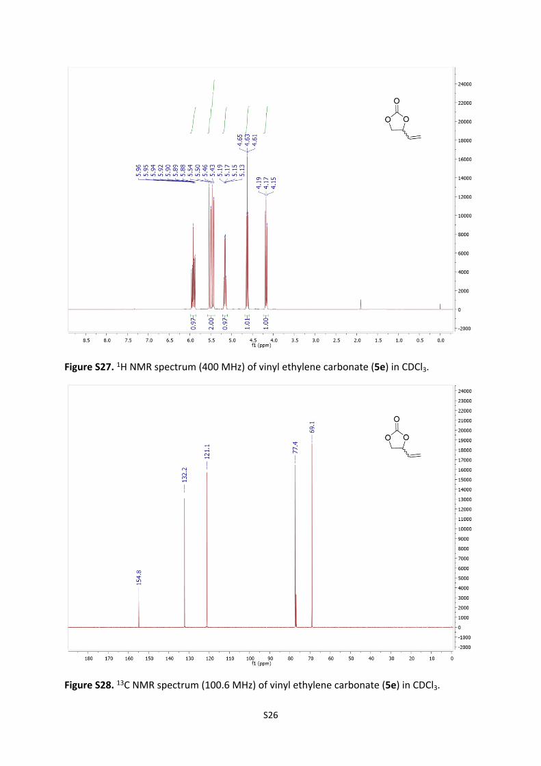
Figure S27. 1H NMR spectrum (400 MHz) of vinyl ethylene carbonate (5e) in CDCl3.
Figure S28. 13C NMR spectrum (100.6 MHz) of vinyl ethylene carbonate (5e) in CDCl3.

S27
Figure S29. 1H NMR spectrum (400 MHz) of 4-methoxymethyl-1,3-dioxolan-2-one (5f) in CDCl3.
Figure S30. 13C NMR spectrum (100.6 MHz) of 4-methoxymethyl-1,3-dioxolan-2-one (5f) in CDCl3.

S28
Figure S31. 1H NMR spectrum (400 MHz) of anhydroerythritol carbonate (5h) in CDCl3.
Figure S32. 13C NMR spectrum (100.6 MHz) of anhydroerythritol carbonate (5h) in CDCl3

S29
2.8 Off-line solid state NMR 2.8.1 General Information13C CPMAS NMR spectra were recorded at 100.6 MHz, on a Bruker Avance III HD spectrometer (9.4 Tesla) equipped with a Standard bore MAS multinuclear probe operated in the 40-400 MHz range. Free induction decays were acquired at room temperature using a standard pulse sequence (Bruker, CP). The spectral width was 405 ppm (40761 Hz). A 90 ° proton excitation pulse of 2.5 µs, a spinlock time of 2 ms and a 2 s relaxation delay were used to collect 300 scans. Spectra were recorded in 4 mm rotor (Bruker) at spinning rate of 12 kHz.
2.8.2 Analysis of Polystyrene-supported 1,1,3,3-tetramethylguanidine (PS-TMG)The rotor spinning rate was 12 kHz in order to avoid spinning side band interfering with the signal of interest. Characteristic signal of the Merrifield resin (CH2Cl: 46.8 ppm) were decreasing in intensity after the reaction with tetramethylguanidine and characteristic signals of PS-TMG appeared at 40.8 ppm (-N-CH3); 53 ppm (-CH2-N=C) and 163.5 ppm (C=N-) (Figure S33).
Figure S33. Solid State NMR spectra of polystyrene-supported TMG (PS-TMG) in red and unmodified Merrifield resin in blue.

S30
3 ReferencesS1. H.-J. Kim, S-II Yoo and J.-S. Chung, New electrolytes and lithium ion battery using the same,
WO Pat. 0152340A1.S2. G. Rokicki, P. Rakoczy, P. Parzuchowski and M. Sobiecki, Green Chem., 2005, 7, 529–539.S3. L. Liu, Q. Li, J. Dai, H. Wang, B. Jin and R. Bai, J. Memb. Sci., 2014, 453, 52–60.S4. N. E. Leadbeater and C. Van Der Pol, J. Chem. Soc. Perkin Trans. 1, 2001, 2831–2835.