Embed Size (px)
Citation preview
FUEL & CARBURETOR MAINTENANCE AND REPAIR MODEL SSI Your Lawn-Boy Trimmer is equipped with a diaphragm type carburetor that has been carefully calibrated. In most instances no adjustment will be required by the operator. 1. Condition of air filter is very important to the operation
of the unit. The condition of the air filter should be checked on a daily basis for a dirty or clogged element. A dirty filter will restrict the air flow. upsetting the fuel- air mixture in the carburetor, resulting in symptoms often mistaken for out-of-adjustment carburetor. For air filter maintenance, see the maintenance section.
2. The carburetor has two basic adjustments, idle speed adjustment and the idle mixture adjustment. The high speed jet is a fixed jet so no high speed adjustment is necessary.
1)Remove choke cover (Fig. 6) to expose the adjust- ments.
2) Make initial settings with the engine stopped: See Note 1. a) Turn the idle speed screw (Fig. 7) out (counter-
clockwise); then in until the carburetor throttle lever just begins to move, continue moving two more full turns. (Waibro carburetors)
b. Turn the idle mixture screw (Fig 8) in (clockwise) until lightly seated, then turn counterclockwise one turn.
3)These initial settings should allow you to start and warm up your trimmer prior to final adjustments.
4)Release the throttle lever to let the engine idle. If the engine stops, turn the idle speed screw clockwise Vi turn at a time as required until engine maintains idle.
YOUR CARBURETOR MAY NEED ADJUSTMENT NOTE: All adjustments should be made when cutting IF YOU NOTICE ANY OF THE line is extended to its maximum cutting length. FOLLOWING CONDITIONS 5)Adjust idle speed and idle mixture screw to achieve
1) Will not idle. a) Adjust idle mixture screw for the fastest idle; then 2) Hesitates or dies on acceleration. turn counterclockwise 1/8 turn. 3) Loss of engine power which is not corrected by air filter b) Squeeze the trigger if the engine falters or hesitates
or muffler cleaning. on accelel'ation, turn the idle mixture screw counter- 4. Unit seems to operate in an erratic or fuel-rich condition clockwise 1/16 turn at a time, just enough to
(noted by excessive smoke out of the exhaust system). achieve rapid acceleration. NOTE: Careless adjustments can seriously damage c) If the idle speed has changed significantly because
your trimmer. of a) & b), above, readjust idle speed screw.
smoothest engine idle:
FUEL & CARBURETOR MAINTENANCE AND REPAIR MODEL SSll Your Lawn-Boy Trimmer is equipped with a diaphragm 2) Make initial settings with the engine stopped: see Note 1.
most instances no adjustment will be required by the wise); then in until the carubretor throttle lever just operator. begins to move, continue moving two more full 1. Condition of air filter is very important to the operation turns. (Walbro carburetors)
of the unit. The condition of the air filter should be b) Turn the idle mixture screw (Fig. 8) in (clockwise) checked on a daily basis for a dirty or clogged element. A dirty filter will restrict the air flow, upsetting the fuel- until lightly seated, then turn counterclockwise one air mixture in the carburetor, resulting in symptoms turn. often mistaken for out-of-adjustment carburetor. For warm up your trimmer prior to final adjustments. 3)These initial settings should allow you to start and air filter maintenance, see the maintenance section.
4)Release the throttle lever to let the engine idle. If the adjustment and the idle mixture adjustment. The high turn at a time as required until engine maintains idle speed jet is a fixed jet so no high speed adjustment is without the cutting head rotating. necessary.
5)Adjust idle speed and idle mixture screw to achieve YOUR CARBURETOR MAY NEED ADJUSTMENT smoothest engine idle: IF YOU NOTICE ANY OF THE a) Adjust idle mixture screw for the fastest idle; then FOLLOWING CONDITIONS turn counterclockwise 1/8 turn. 1) Will not idle. b) Squeeze the trigger if the engine falters or hesitates
type carburetor that has been carefully calibrated. In a) Turn the idle speed Screw (Fig. 7) out (counterclock-
2. The carburetor has two basic adjustments, idle speed engine stops, turn the idle speed Screw clockwise
2) Hesitates or dies on acceleration. 3) Loss of engine power which is not corrected by air filter
or muffler cleaning. 4. Unit seems to operate in an erratic or fuel-rich condition
(noted by excessive smoke out of the exhaust system). 5. Head continues to rotate at idle when the head is in
contact with the ground. NOTE: All adjustments should be made when cutting
line is extended to its maximum cutting length, and the cutting head is in contact with the ground.
1)Remove choke cover (Fig. 6) to expose the adjust- ments.
on acceleration, turn the idle mixture screw counter- clockwise 1/16 turn at a time, just enough to achieve rapid acceleration.
(1) High enough to disengage the centrifugal clutch
d) Recheck for proper operation, repeat steps b) and
NOTE: The weight of the head and wand when in con- tact with the ground should stop the head from rotating. Because the head rotates on antifric- tion bearings, it is normal for the head to rotate when not in contact with the ground.
c) Adjust idle speed.
and stop the head from rotating.
c) above,' if necessary

SSI SSll MAINTENANCE AIR FILTER NOTE:
Fig. Remove carburetor cover mounting screws.
Fig. 2 Remove filter from carburetor cover.
CLEAN AND RE-OIL AIR FILTER EVERY 10 HOURS
Your unit's air filter is one of the most important areas to maintain. If the air filter is not cared for as described on the carburetor cover or as shown in Figs. 1 thru 5, you will void your warranty.
Fig. 3 -Wash filter in kerosene, petroleum solvent or detergent.
Fig. 5 Squeeze filter to spread oil and re-install in carburetor cover. engine oil.
Fig. 4 Squeeze dry and re-oil air filter with SA€ 30
CARBURETOR ADJUSTMENTS MAINTENANCE AND REPAIR (CON'T)
Fig. 7 View showing idle speed adjustment screw
SERVICE BULLETIN REFERENCES REVISED 1983
Fig. 8 View showing idle mixture adjustment with cut-a-way air filter cover in place.
NOTE:
When closing idle mixture adjustment screw, turn finger-tight only. Forcing adjustment screw with screwdriver will cause serious damage to seat.
STARTING WALBRO CARBURETOR REASSEMBLY SSI SSII
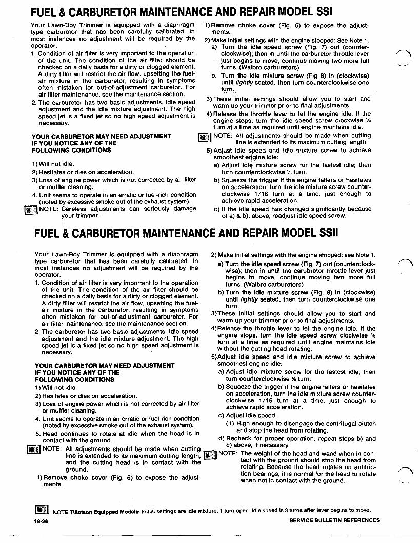
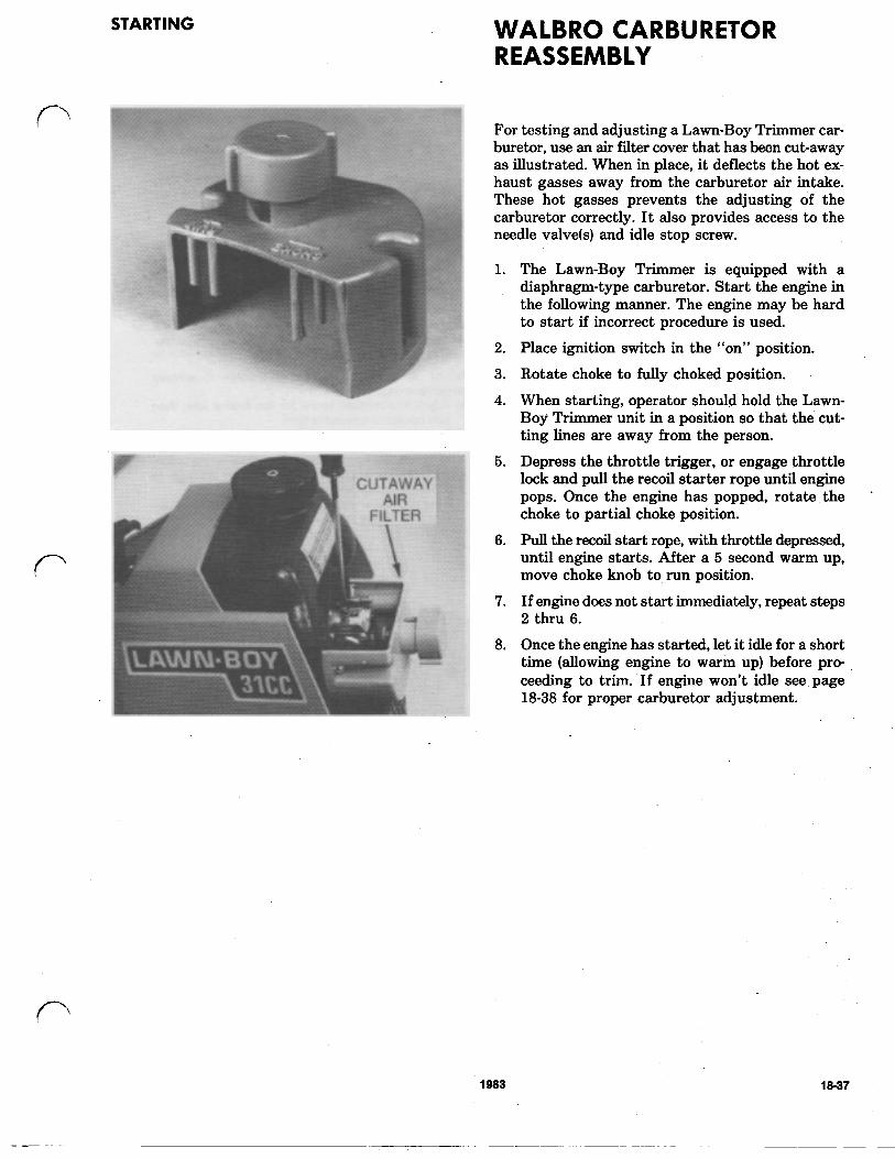
For testing and adjusting a Lawn-Boy Trimmer car- buretor, use & air filter cover that has been cut-away as illustrated. When in place, it deflects the hot ex- haust gasses away from the carburetor air intake. These hot gasses prevents the adjusting of the carburetor correctly. It also provides access to the needle valve(s) and idle stop screw.
1.
2.
3.
4.
5.
6.
7.
8.
The Lawn-Boy Trimmer is equipped with a diaphragm-type carburetor. Start the engine in the following manner. The engine may be hard to start if incorrect procedure is used.
Place ignition switch in the “on” position.
Rotate choke to fully choked position.
When starting, operator should hold the Lawn- Boy Trimmer unit in a position so that the cut- ting lines are away from the person.
Depress the throttle trigger, and pull the recoil starter rope until engine pops. Once the engine has popped, rotate the choke to partial choke position.
Pull the recoil start rope, with throttle depressed, until engine starts. After a 5 second warm up, move choke knob to run position.
If engine does not start immediately, repeat steps 2 thru 6.
Once the engine has started, let it idle for a short time (allowing engine to warm up) before pro- ceeding to trim. If engine won’t idle see page 18-38 for ,proper carburetor adjustment.
18-27A 1983
SSI SSll
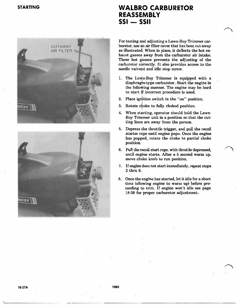
Fig. 10 Disconnect fuel line from carburetor fuel inlet.
FOR CARBURETOR REPAIR AND SERVICE REFER TO PAGES 18-6 THROUGH 18-15.
Fig. 11 Make sure no foreign material has clogged reed plate passages.
Fig. 13 Check reed for freedom of movement.
Fig. 15 Reed plate and carburetor mount assembly showing reed plate, reed backup and mounting screws.
Fig. 12 Remove four mounting screws from reed plate and carburetor mount.
Fig. 14 To replace reed if necessary, remove two mounting screws as shown
REED BACKUP PLATE MUST BE FLUSH WITH REED BLOCK WHEN ASSEMBLED
NOTE
carburetor mount assembly the curved portion MUST Fig. 16 When reassembling reed plate and reed backup to
BE installed as shown.
18-28 SERVICE BULLETIN REFERENCES
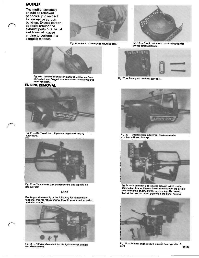
ENGINE REMOVAL when necessary.
outer cowls. Fig. 21 Remove all the phillips mounting screws holding
direction until free of clamp Fig. 22 Unscrew head adjustment counterclockwise
Fig. 23 -Turn trimmer over and remove the side opposite the gas tank filler.
NOTE
Routing and assembly of the following for reassembly: fuel line, throttle return spring, throttle wire housing, switch and wire routing.
Fig. 24 -With the left side removed proceed to lift from the housing handle area, the switch and lead assembly, the throttle lever and spring, and the throttle wire housing. Also loosen the fuel line from the retaining groove in the starter housing.
Fig. 25 -Trimmer shown with throttle, ignition switch and gas tank disconnected.
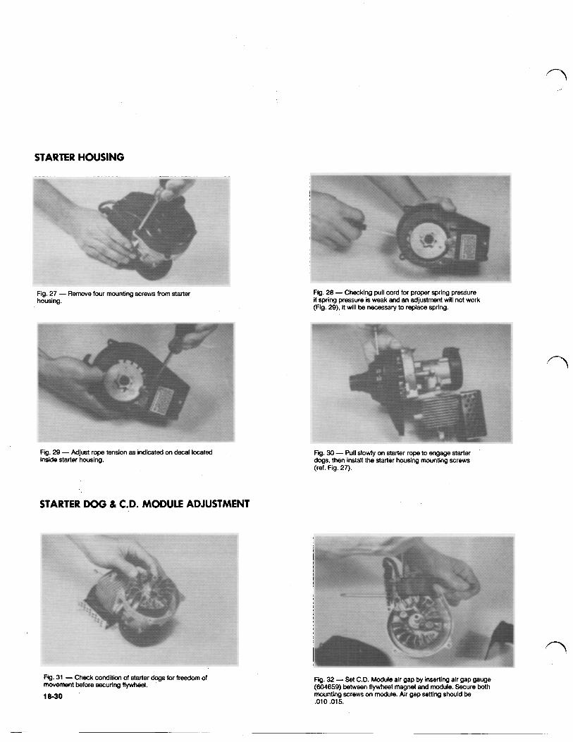
STARTER HOUSING
Fg. 28 Checking pull cord for proper spring pressure if spring pressure is weak and an adjustment will not work (Fig. 29), it will be necessary to replace spring.
Fig. 27 Remove four mounting screws from starter housing.
Fg. 29 Adjust rope tension as indicated on decal located inside starter housing.
STARTER DOG & C.D. MODULE ADJUSTMENT
Fig. 31 Check condition of starter dogs for freedom of movement before securing flywheel.
18-30
Fig. 30 -'Pull slowly on starter rope to engage starter d o g s , then install the starter housing mounting screws (ref. Fig. 27).
Fg. 32 -:Set C.D. Module air gap by inserting alr gap gauge (604659) between flywheel magnet and module. Secure both mounting screws on module. Air gap setting should be .010.015.
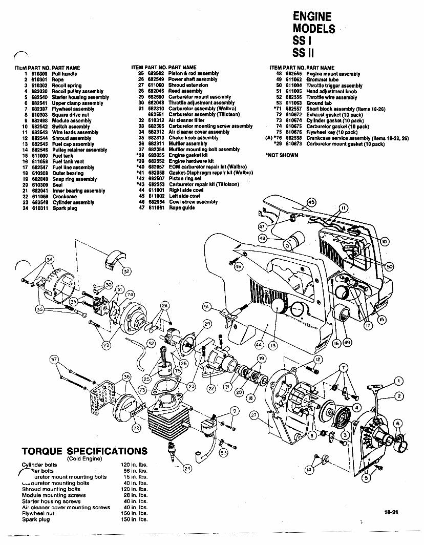
ITEM PART NO. PART NAME 1 610360 Pull handle 2 610301 Rope 3 610302 Recoil spring 4 682030 Recoil pulley assembly 5 682540 Starter housing assembly 6 682541 Upper clamp assembly 7 682307 Flywheel assembly 8 610303 Square drive nut 9 682498 Module assembly
10 682542 Switch assembly 11 682543 Wire leads assembly 12 682544 Shroud assembly 13 682545 Fuel cap assembly 14 682546 Pulley retainer assembly 15 611000 Fuel tank 16 611058 Fuel tank vent 17 682547 Fuel line assembly 18 610308 Outer bearlng
20 610309 Seal 19 682040 Snap ring assembly
21 682041 Inner bearlng assembly 22 611059 Crankcase 23 682548 Cyllnder assembly 24 610311 Spark plug
ITEM PART NO. PART NAME 25 682502 Piston & rod assembly 26 682549 Power shaft assembly 27 61 1060 Shroud extension 28 682046 Reedassembly 29 682550 Carburetor mount assembly 30 682048 Throttle adjustment assembly 31 682310 Carburetor assembly (Walbro)
682551 Carburetor assembly (Tlllotson) 32 610312 Air cleaner fllter 33 682505 Carburetor mounting screw assembly
35 682313 Choke knob assembly 34 682312 Air cleaner cover assembly
36 682311 Muffler assembly 37 682054 Muffler mounting bolt assembly
*38 682055 Engine gasket kit *39 682552 Engine hardware kit *40 682057 EOM carburetor repair kit (Walbro) *41 682058 Gasket-Diaphragm repair kit (Walbro) *42 682507 Piston ring set *43 682553 Carburetor repalr kit (Tillotson) 44 611001 Right side cowl 45 611002 Lett side cowl
ENGINE MODELS ss I ss II
ITEM PART NO.PART NAME 48 682555 Engine mount assembly 49 611062 Grommet tube 50 611004 Throttle trigger assembly 51 611005 Head adjustment knob
53 611063 Ground tab 52 682556 Throffle wire assembly
*71 682557 Short block assembly (Items 18-26) 72 610672 Exhaust gasket(10 pack) 73 610674 Cylinder gasket (10 pack) 74 610675 Carburetor gasket (10 pack) 75 610676 Flywheel key (10 pack)
(A) *76 682558 Crankcase service assembly (Items 18-22,26)
"NOT SHOWN
*29 610673 Carburetor mount gasket (10 pack)
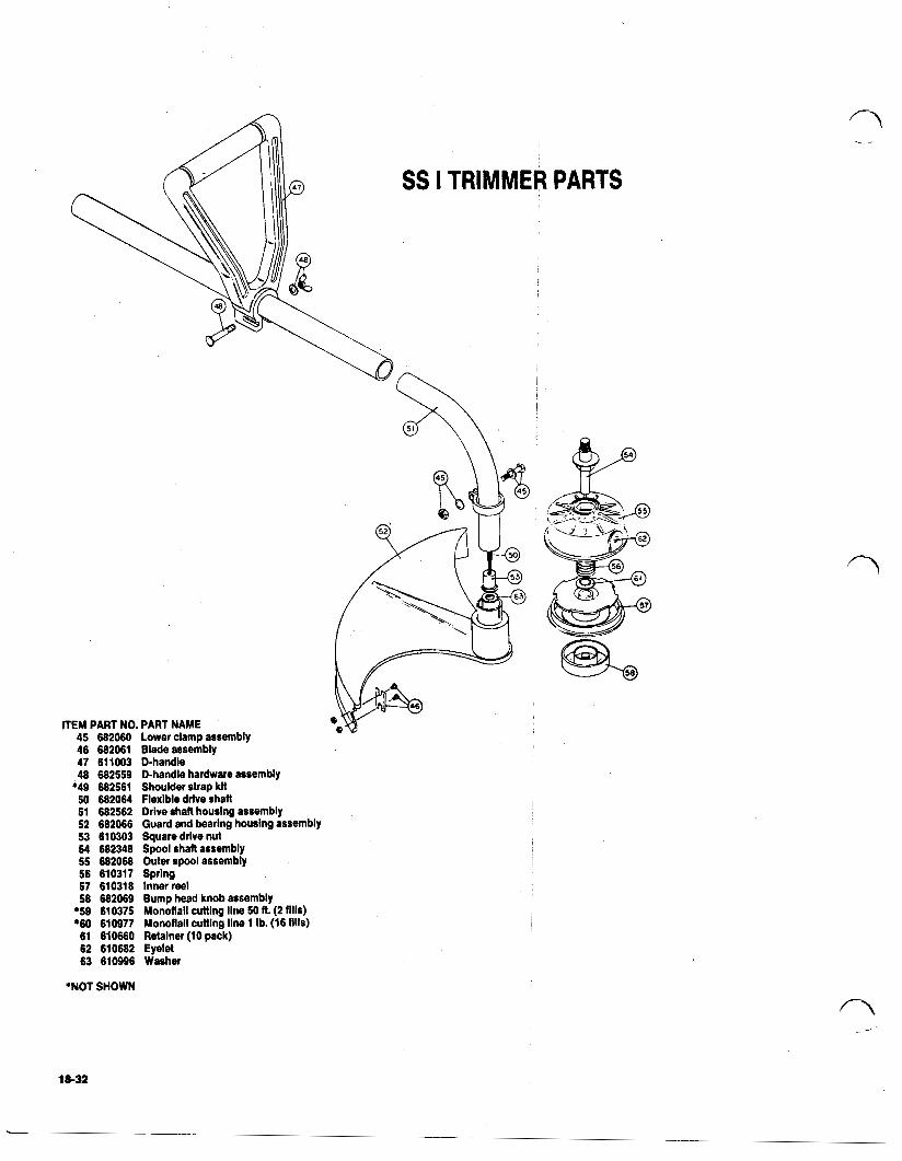
ITEM PART NO. PART NAME 45 682060 Lower clamp assembly 46 682061 Blade assembly 47 611003 D-handle 48 682559 D-handle hardware assembly
*49 682561 Shoulder strap klt 50 682064 Flexible drive shaft 51 682562 Drive shaft housing assembly 52 682066 Guard and bearing housing assembly 53 610303 Square drive nut 54 682348 Spool shaft assembly 55 682068 Outer spool assembly 56 610317 Spring 57 610318 Inner reel
*59 610375 Monoflall cutting line 50 ft (2 fills) 58 682069 Bump head knob assembly
'60 610977 Monoflail cuttlng line 1 Ib. (16 fills) 61 610660 Retainer (10 pack) 62 610682 Eyelet 63 610996 Washer
*NOT SHOWN
18-32
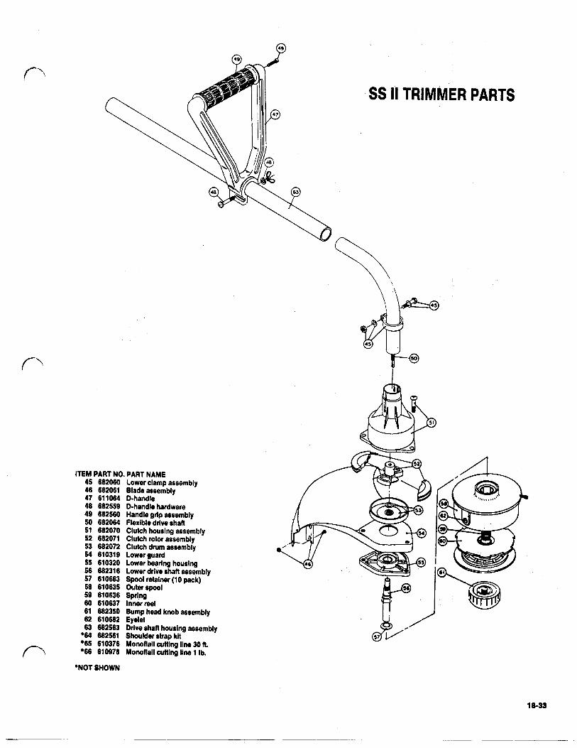
ITEM PART NO. PART NAME 45 682660 Lower clamp assembly 46 682061 Blade assembly 47 611064 D-handle 48 682559 D-handle hardware 49 682560 Handle grlp assembly 50 682064 Flexible drive shaft 51 682070 Clutch houslng assembly 52 682071 Clutch rotor assembly 53 682072 Clutch drum assembly 54 610319 Lower guard 55 610320 Lower bearing housing 56 682316 Lower drive shaft assembly 57 610683 Spool retainer (1 0 pack) 58 610635 Outer spool 59 610636 Sprlng 60 610637 Inner reel 61 682350 Bump head knob assembly 62 610682 Eyelet 63 682563 Drive shaft housing assembly
*64 682561 Shoulder strap kit *65 610376 Monoflall cuttlng line 30 A *66 610978 Monoflall cutting line 1 Ib.
SS II TRIMMER PARTS
*NOT SHOWN
18-33
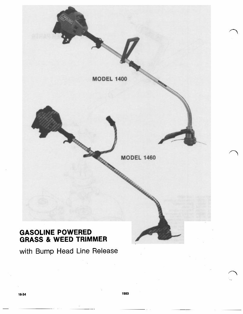
GASOLINE POWERED GRASS & WEED TRIMMER with Bump Head Line Release
18-34 1983
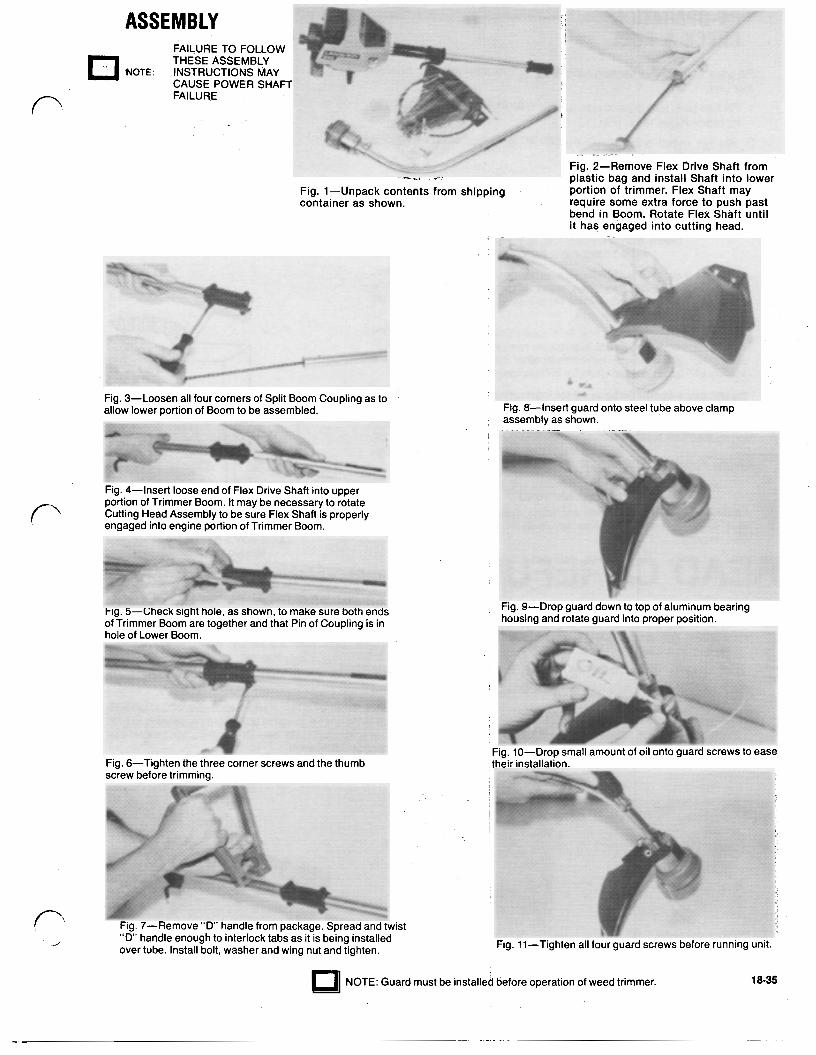
Fig. 3-Loosen all four corners of Split Boom Coupling as to allow lower portion of Boom to be assembled.
Fig. 4-Insert loose end of Flex Drive Shaft into upper portion of Trimmer Boom. It may be necessary to rotate Cutting Head Assembly to be sure Flex Shaft is properly engaged into engine portion of Trimmer Boom.
Fig. 5-Check sight hole, as shown, to make sure both ends of Trimmer Boom are together and that Pin of Coupling is in hole of Lower Boom.
Fig. 6-Tighten the three corner screws and the thumb screw before trimming.
Fig. 7-Remove “D’ handle from package. Spread and twist “D” handle enough to interlock tabs as it is being installed over tube. Install bolt, washer and wing nut and tighten.
_.-
Fig. 8-Insert guard onto steel tube above clamp assembly as shown.
Fig. 9-Drop guard down to top of aluminum bearing housing and rotate guard into proper position.
Fig. 10-Drop small amount of oil onto guard screws to ease their installation.
Fig. 11-Tighten all four guard screws before running unit.
NOTE: Guard must be installed before operation of weed trimmer. 18-35
PRE-OPERATION CHECK & FUEL
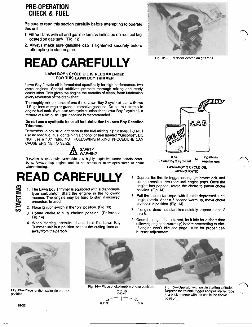
Be sure to read this section carefully before attempting to operate this unit. 1. Fill fuel tank with oil and gas mixture as indicated on red fuel tag
2. Always make sure gasoline cap is tightened securely before located on gas tank. (Fig. 12)
attempting to start engine.
AD CAREFULLY LAWN BOY 2CYCLE OIL IS RECOMMENDED
FOR THIS LAWN BOY TRIMMER Lawn-Boy 2 cycle oil is formulated specifically for high performance, two cycle engines. Special additives promote thorough mixing and ready combustion. This gives the engine the benefits of clean, fresh lubrication every revolution of the crankshaft. Thoroughly mix contents of one 8-oz Lawn-Boy 2 cycle oil can with two U.S. gallons of regular grade automotive gasoline. Do not mix directly in engine fuel tank. If you use two cycle oil other than Lawn-Boy 2 cycle oil, a mixture of 6 oz. oil to 1 gal. gasoline is recommended.
Do not use a synthetic base oil for lubrication In Lawn-Boy Gasoline Trimmers. Remember to pay strict attention to the fuel mixing instructions. DO NOT use no-lead fuel, fuel containing alcohol or fuel labeled “Gasohol”. DO NOT use a 40:l ratio. NOT FOLLOWING MIXING PROCEDURE CAN CAUSE ENGINE TO SEIZE.
SAFETY WARNING
Gasoline is extremely flammable and highly explosive under certain condi- tions. Always stop engine, and do not smoke or allow open flame spark when refueling.
Fig. 12-Fuel decal located on gas tank.
8 oz. 2 gallons Lawn-Boy 2 cycle oil regular gas
LAWN-BOY 2 CYCLE OIL
READ CARFULLY 5. Depress the throttle trigger, or engage throttle lock, and pull the recoil starter rope until engine pops. Once the
MIXING RATIO
1. The Lawn Boy Trimmer is equipped with a diaphragm- type carburetor. Start the engine in the following manner. The engine may be hard to start if incorrect procedure is used.
2. Place ignition switch in the “on” position. (Fig. 13) 3. Rotate choke to fully choked position. (Reference
engine has popped, rotate the choke to partial choke position. (Fig. 14)
6. Pull the recoil start rope, with throttle depressed, until engine starts. After a 5 second warm up, move choke knob to run position. (Fig. 14)
7. If engine: does not start immediately, repeat steps 2 thru 6.
STARTING WA,LBRO CARBURETOR REASSEMBLY
For testing and adjusting a Lawn-Boy Trimmer car- buretor, use an air filter cover that has been cut-away as illustrated. When in place, it deflects the hot ex- haust gasses away from the carburetor air intake. These, hot gasses prevents the adjusting of the carburetor correctly. It also provides access to the needle valve(s) and idle stop screw.
1. The Lawn-Boy Trimmer is equipped with a diaphragm-type carburetor. Start the engine in the following manner. The engine may be hard to start if incorrect procedure is used.
2. Place ignition switch in the “on” position.
3. Rotate choke to fully choked position.
4. When starting, operator should hold the Lawn- Boy Trimmer unit in a position so that the cut- ting lines are away from the person.
5. Depress the throttle trigger, or engage throttle lock and pull the recoil starter rope until engine pops. Once the engine has popped, rotate the choke to partial choke position.
6. pull the recoil start rope, with throttle depressed, until engine starts. After a 5 second warm up, move choke knob to run position.
2 thru 6. 7. If engine does not start immediately, repeat steps
8. Once the engine has started, let it idle for a short time (allowing engine to warm up) before pro- ceding to trim. If engine won’t idle see page 18-38 for proper carburetor adjustment.
1983 18-37
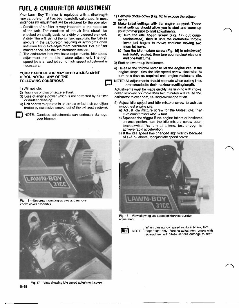
FUEL & CARBURETOR ADJUSTMENT Your Lawn Trimmer is equipped with a diaphragm 1) Remove choke cover (Fig. 16) to expose adjust- type carburetor that has been carefully calibrated. In most ments. instances no adjustment will be required by the operator. 2) Make initial with the engine stopped These 1. Condition of air filter is very important to the operation initial settings should allow you to start and warm up
of the unit. The condition of the air filter should be your trimmer prior to final adjustments. checked on a daily basis for a dirty or clogged element. a) Turn the idle speed screw (Fig. 17) out coun- A dirty filter will restrict the air flow, upsetting the fuel-air terclockwise), then in until the carburetor throttle mixture in the carburetor, resulting in symptoms often lever just begins to move; continue moving two mistaken for out-of-adjustment carburetor. For air filter more full turns. maintenance, see the maintenance section. b) Turn the idle mixture screw (Fig. 18) in (clockwise)
2. The carburetor has two basic adjustments, idle speed adjustment and the idle mixture adjustment. The high
until lightly Seated, then turn counterclockwise one and one half turns.
speed jet is a fixed jet so no high speed adjustment is 3) Start and warm up the trimmer. necessary. 4) Release the throttle lever to let the engine idle. If the
YOUR CARBURETOR MAY NEED ADJUSTMENT engine Stops, turn the idle speed screw clockwise 1/8 IF YOU NOTICE ANY OF THE turn at a time as required until engine maintains idle. FOLLOWING CONDITIONS NOTE: All adjustments should be made when cutting lines
1) Will not idle. Adjustments must be made quickly, as running with choke 2) Hesitates or dies on acceleration. cover removed for more than two minutes will cause the 3) LOSS of engine power which is not corrected by air filter carburetor to Over heat, causing erratic operation.
4) Unit Seems to operate in an erratic or fuel-rich condition 5) Adjust idle speed and idle mixture Screw to achieve
are extended to their maximum cutting length.
or muffler cleaning.
(noted by excessive smoke out of the exhaust system). smoothest engine idle: a) Adjust idle mixture screw for the fastest idle; then
your trimmer. b) Squeeze the trigger if the engine falters or hesitates on acceleration, turn the idle mixture screw coun- terclockwise 1/16 turn at a time, just enough to achieve rapid acceleration.
c) If the idle speed has changed significantly because of a) 8, b) above. readiust idle weed screw.
NOTE: Careless adjustments can seriously damage turn counterclockwise 1/8 turn.
Fig. 16-Unscrew mounting screws and remove choke cover assembly.
Fig. 18-View showing low speed mixture carburetor adjustment.
When closing low speed mixture screw, turn NOTE finger-tight only. Forcing adjustment screw with
screwdriver will cause serious damage to seat.
Fig. 17-View showing idle speed adjustment screw. 18-38
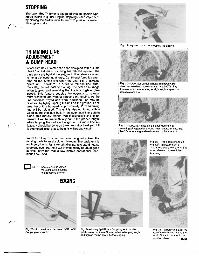
STOPPING The Lawn Boy Trimmer is equipped with an ignition type on/off switch (Fig. 12). Engine stopping is accomplished by moving the switch lever to the “off’ position, causing the engine to stop.
Fig. 19-Ignition switch for stopping the engine.
TRIMMING LINE ADJUSTMENT & BUMP HEAD Your Lawn Boy Trimmer has been designed with a Bump Head™ or automatic trimming line release system. The basic principle behind the automatic line release system is the use of centrifugal force. Centrifugal force is gener- ated on the cutting line when the unit is in a spinning operation. Therefore, in order to release line auto- matically, the unit must be running. The best r.p.m. range when tapping and releasing the line is a high engine speed. This feature enables the operator to release more trimming line without stopping the engine. As the line becomes frayed and worn, additional line may be released by lightly tapping the unit on the ground. Each time the unit is bumped, approximately 1” of trimming line will be released. The unit is also equipped with a weed guard that has built in an automatic line cutting blade. this merely means that if excessive line is re- leased, it will be automatically cut to the proper length. when tapping the unit on the ground for more line re- lease, it should be done on bare ground or hard soil. If it is attempted in tall grass, the unit will probably stall.
Fig. 20-Operator bumping head in a downward direction to extend more trimming line. NOTE: The trimmer must be operating at high engine speed to release more line.
Fig. 21-Decorative scalping is accomplished by removing all vegetation around trees, posts, fences, etc Use 30-degree angle when trimming in this method.
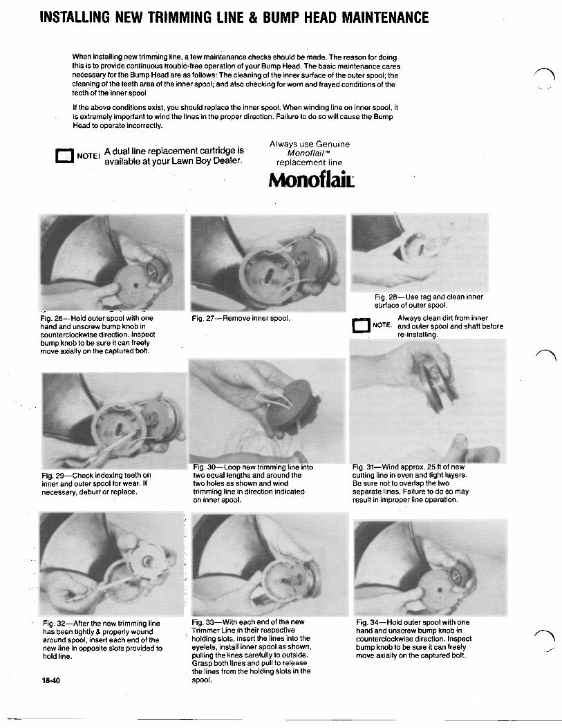
INSTALLING NEW TRIMMING LINE & BUMP HEAD MAINTENANCE
When installing new trimming line, a few maintenance checks should be made. The reason for doing this is to provide continuous trouble-free operation of your Bump Head. The basic maintenance cares necessary for the Bump Head are as follows: The cleaning of the inner surface of the outer spool; the cleaning of the teeth area of the inner spool; and also checking for worn and frayed conditions of the teeth of the inner spool
If the above conditions exist, you should replace the inner spool. When winding line on inner spool, it is extremely important to wind the lines in the proper direction. Failure to do so will cause the Bump Head to operate incorrectly.
A dual line replacement cartridge is available at your Lawn Boy Dealer. replacement l ine
Always use Genuine NOTE! Monoflail ™
Monoflair
Fig. 26-Hold outer spool with one hand and unscrew bump knob in counterclockwise direction. Inspect bump knob to be sure it can freely move axially on the captured bolt.
Fig. 29-Check indexing teeth on inner and outer spool for wear. If necessaiy, deburr or replace.
Fig. 27-Remove inner spool. NOTE: and outer spool and shaft before
Always clean dirt from inner
re-installing.
Fig. 30-Loop new trimming line into Fig. 31-Wind approx. 25 ft of new two equal lengths and around the cutting line in even and tight layers. two holes as shown and wind Be sure not to overlap the two trimming line in direction indicated separate lines. Failure to do so may on inner spool. result in improper line operation.
Fig. 32-After the new trimming line has been tightly & properly wound around spool, insert each end of the new line in opposite slots provided to hold line.
18-40
Fig. 33-With each end of the new Trimmer Line in their respective holding slots, insert the lines into the eyelets, install inner spool as shown, pulling the lines carefully to outside. Grasp both lines and pull to release the lines from the holding slots in the spool.
Fig. 34-Hold outer spool with one hand and unscrew bump knob in counterclockwise direction. Inspect bump knob to be sure it can freely move axially on the captured bolt.
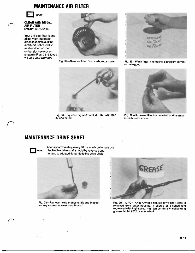
MAINTENANCE AIR FILTER NOTE:
CLEAN AND RE-OIL AIR FILTER EVERY 10 HOURS
Your unit's air filter is one of the most important areas to maintain. If the air filter is not cared for as described on the carburetor cover or as shown in Figs. 35-38, you will void your warranty.
Fig. 34-Remove filter from carburetor cover. Fig. 35-Wash filter in kerosene, petroleum solvent or detergent.
Fig. 36-Squeeze dry and re-oil air filter with SAE Fig. 37-Squeeze filter to spread oil and re-install 30 engine oil. in carburetor cover.
MAINTENANCE DRIVE SHAFT After apporoximately every 10 hours of continuous use.
NOTE the flexible drive shaft should be reversed end for end to add additional life to the drive shaft.
Fig. 38-Remove flexible drive shaft and inspect Fig. 39-IMPORTANT Anytime flexible drive shaft core is for any excessive wear conditions. removed from outer housing, it should be cleaned and
regreased with high speed, high temperature wheel bearing grease, Mobil #532 or equivalent.
18-41
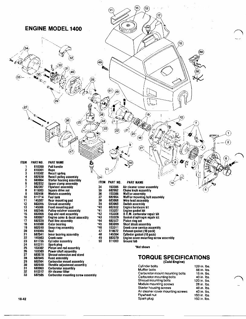
ITEM 1 2 3 4 5 6 7 8 9
10 11 12 13 14 15 16 17 18 19 20 21 22 23 24 25 26 27 28 29 30 31 32 33
18-42
PART NO. 610300 610301 61 0302 682030 683064 682032 682307 61 0303 682498 611714 145307 683065
682546 145308
683066 683067 682039 610308 682040 610309 682041 145563 61 1735 61 031 1 153302 153303 683078 682046 682504 682048 683063 61 031 2 682505
Shroud assembly 39 683069 Front mounting pad '40 682552 Pulley retainer assembly *'41 153307 Cap and vent assembly '42 153308 Engine cover & decal assembly '43 153309 Fuel line assembly '44 682507 Outer bearing '45 683099 Snap ring assembly '46 153311 Seal 47 610672 Inner bearing assembly 48 145564 Crank case 49 683070 Cylinder assembly 50 611063 Spark plug Piston and rod assembly
Shroud extension and stand Power shaft assembly
Reed assembly Carburetor mount assembly Throttle adjustment assembly Carburetor assembly Air cleaner filter Carburetor mounting screw assembly
Switch assembly Engine hardware kit Engine gasket kit O.E.M. carburetor repair kit Gasket diaphragm repair kit Piston ring set Short block assembly Crank case service' assembly Exhaust gasket (10 pack) Cylinder gasket (10 pack)
Ground tab Engine cover mounting screw assembly
'Not shown
TORQUE SPECIFICATIONS (Cold Engine)
Cylinder bolts 120 in. Ibs. Muffler bolts 56 in. Ibs. Carburetor mount mounting bolts 15 in. Ibs. Carburetor mounting bolts 40 in. Ibs. Shroud mounting bolts 120 in. Ibs. Module mounting screws 28 in. Ibs. Starter housing screws 40 in. Ibs. Air cleaner cover mounting screws 40 in. Ibs. Flywheel nut Spark plug
150 in. Ibs. 150 in. Ibs.
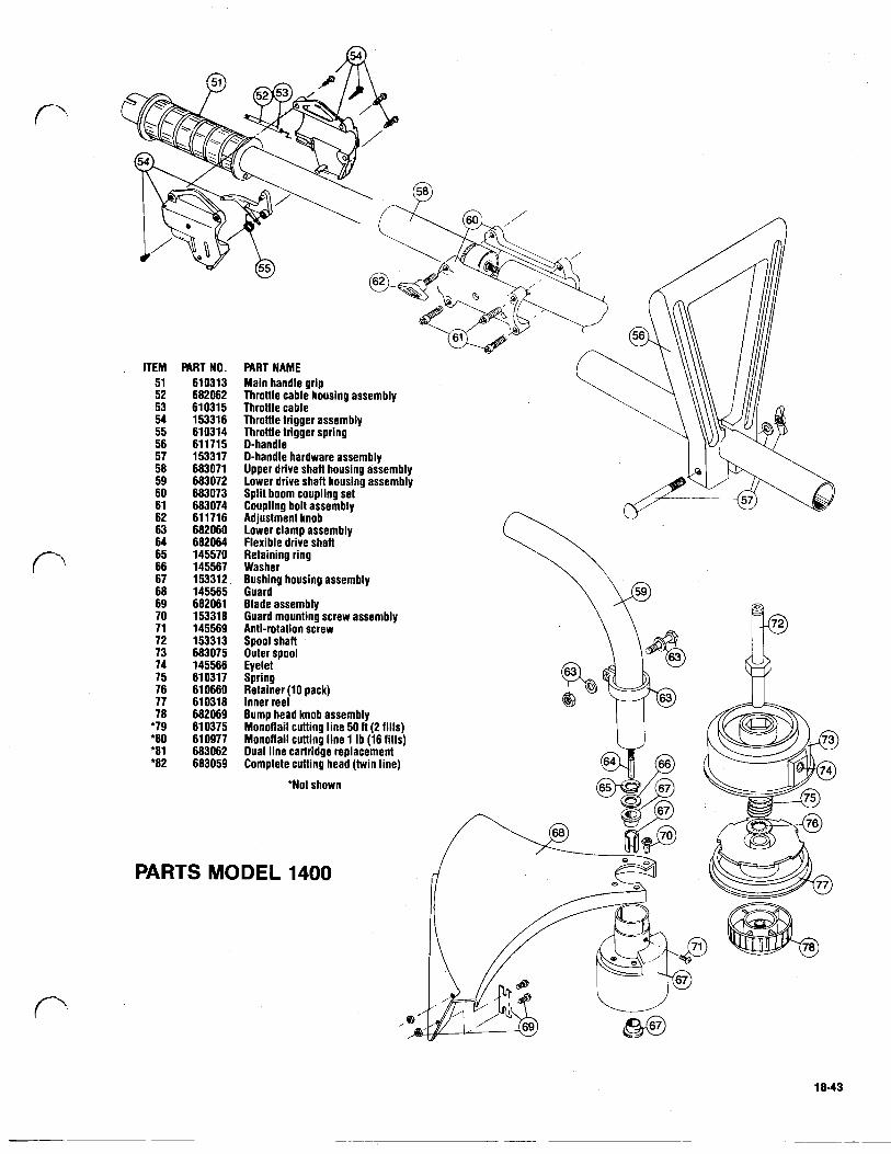
ITEM 51 52 53 54 55 56 57 58 59 60 61 62 63 64 65 66 67 68 69 70 71 72 73 74 75 76 77 78
*'79 '80 '81 '82
PART NO. 610313 682062 61 031 5 153316 610314 611715 153317 683071 683072 683073 683074 611716 682060 682064 145570 145567 153312 145565 682061 153318 145569 15331 3 683075 145566 61 031 7 61 0660 610318 682069 61 0375 610977 683062 683059
PART NAME Main handle grip Throttle cable housing assembly Throttle cable Throttle trigger assembly Throttle trigger spring D-handle
Upper drive shall housing assembly D-handle hardware assembly
Split boom coupling set Lower drive shall housing assembly
Adjustment knob Coupling bolt assembly
Lower clamp assembly Flexible drive shall
Washer Retaining ring
Bushing housing assembly Guard Blade assembly Guard mounting screw assembly Anti-rotation screw Spool shaft Outer spool Eyelet Spring Retainer (10 pack) Inner reel Bump head knob assembly Monoflail cutting line 50 ft (2 fills) Monoflail cutting line 1 Ib (16 fills) Dual line cartridge replacement Complete cutting head (twin line)
'Not shown
PARTS MODEL 1400
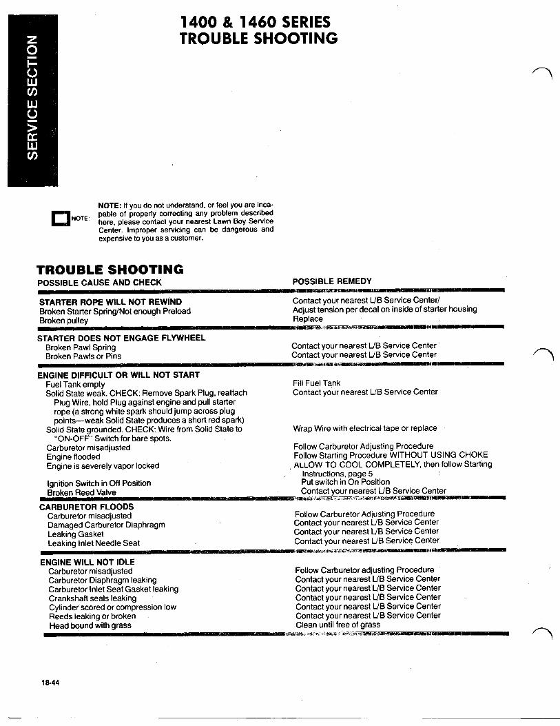
1400 & 1460 SERIES TROUBLE SHOOTING
NOTE
NOTE: If you do not understand, or feel you are inca- pable of properly correcting any problem described here, please contact your nearest Lawn Boy Service Center. Improper servicing can be dangerous and expensive to you as a customer.
TROUBLE SHOOTING POSSIBLE CAUSE AND CHECK POSSIBLE REMEDY
STARTER ROPE WILL NOT REWIND Contact your nearest L/B Service Center Broken Starter Spring/Not enough Preload Adjust tension per decal on inside of starter housing Broken pulley Replace
STARTER DOES NOT ENGAGE FLYWHEEL Broken Pawl Spring Contact your nearest L/B Service Center
Contact your nearest L/B Service Center
Fuel Tank empty Fill Fuel Tank Solid State weak. CHECK: Remove Spark Plug, reattach Contact your nearest L/B Service Center
Plug Wire, hold Plug against engine and pull starter rope (a strong white spark should jump across plug points-weak Solid State produces a short red spark)
“ON-OFF’ Switch for bare spots. Solid State grounded. CHECK: Wire from Solid State to Wrap Wire with electrical tape or replace
Carburetor misadjusted Follow Carburetor Adjusting Procedure Engine flooded Follow Starting Procedure WITHOUT USING CHOKE Engine is severely vapor locked ALLOW TO COOL COMPLETELY, then follow Starting
Ignition Switch in Off Position Put switch in On Position Broken Reed Valve Contact your nearest L/B S
Carburetor misadjusted Follow Carburetor Adjusting Procedure Damaged Carburetor Diaphragm Contact your nearest L/B Service Center Leaking Gasket Contact your nearest L/B Service Center
Contact our nearest L/B Service Center
Instructions, page 5
Carburetor misadjusted Follow Carburetor adjusting Procedure Carburetor Diaphragm leaking Contact your nearest L/B Service Center Carburetor Inlet Seat Gasket leaking Contact your nearest L/B Service Center Crankshaft seals leaking Contact your nearest L/B Service Center Cylinder scored or compression low Contact your nearest L/B Service Center Reeds leaking or broken Contact your nearest L/B Service Center
an until free

TROUBLE SHOOTING CONTINUED POSSIBLE CAUSE AND CHECK POSSIBLE REMEDY
ENGINE BACKFIRES OR MISFIRES Fuel Mix improper or contaminated Drain tank and refill with freshly mixed fuel Spark Plug fouled Clean Spark Plug and regap or replace Solid State intermittently shorting. CHECK: loose or bare Tighten assemblies, wrap wires
Defective Reed Assembly Contact your nearest L/B Service Center
Shaft broken Replace shaft Flex Shaft not engaged Re-assemble properly
wires or loose assemblies
HEAD WILL NOT TURN WHEN THROTTLE LEVER IS SQUEEZED
ENGINE WILL NOT ACCELERATE Carburetor misadjusted Foilow Carburetor Adjusting Procedure Dirty Air Filter Clean Air Filter or replace Spark Plug fouled or Solid State weak Clean Spark Plug and regap or replace Carbon build-up Clean Exhaust Port and Muffler Carburetor Diaphragm Cover loose or Diaphragm Gasket leaking Contact your nearest L/B Service Center Broken Reed Valve Contact your nearest L/B Service Center
ENGINE LACKS POWER OR DIES IN THE CUT Dirty Air Filter Clean Air Filter or replace Carbon build-up Clean Exhaust Port and Muffler, page 18 Low compression. CHECK: Compression pressure tests Contact your nearest L/B Service Department
below 90 PSI or lessened engine resistance to pulling starter rope
HEAD WILL NOT ADVANCE LINE Out of Line Refill with Genuine Monoflail® Cutting Line Bump Knob Bound Up Replace Indexing Teeth Worn or Burred Replace Head Dirty Clean Line Welded or Dis,assemble, remove welded section and rewind line Line Twisted When Refilled per instructions Not Enough Line Exposed Manually index until 4 of line shows
outside the head.
ENGINE SPECIFICATION S Spark plug gap .025
Flywheel torque 150 in. Ibs. C. D. Module air gap .010-.015 Piston ring end gap .025 max. Piston side ring clearance .005 max. Compression avg. 120 Ibs.; min. 90 Ibs. Piston ring width .052 min. Spark plug Champion DJ8J
Fig. 1-Remove Screw, Spark Plug Wire & Shroud Fig. 2-Remove (2) Wire Leads at Ignition Module. Extension Stand. Be sure that wire leads are secured in retainer slot
before reassembly. 18-45
...
ENGINE COVER REMOVAL (CON’T.)
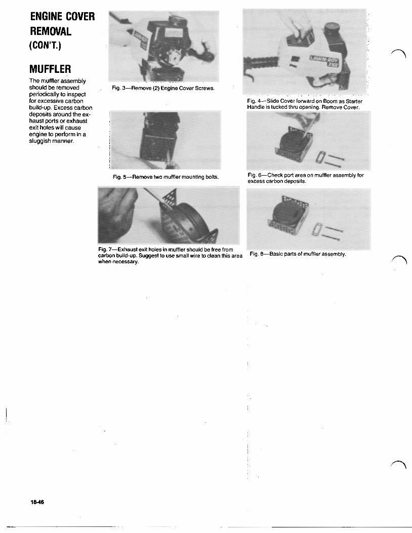
MUFFLER The muffler assembly should be removed periodically to inspect for excessive carbon build-up. Excess carbon deposits around the ex- haust ports or exhaust exit holes will cause engine to perform in a sluggish manner.
Fig. 4-Slide Cover forward on Boom as Starter Handle is tucked thru opening. Remove Cover.
Fig. 5-Remove two muffler mounting bolts. Fig. 6-Check port area on muffler assembly for excess carbon deposits.
18-46
STARTER HOUSING
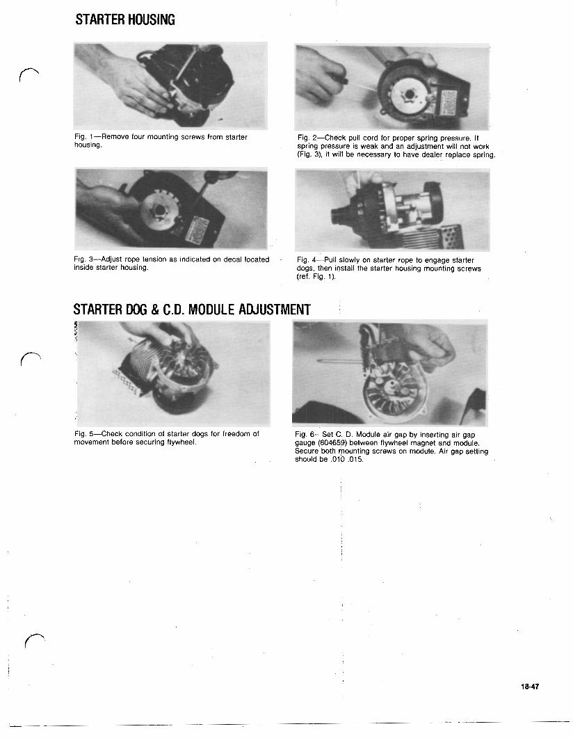
Fig. 1-Remove four mounting screws from starter Fig. 2-Check pull cord for proper spring pressure. If housing. spring pressure is weak and an adjustment will not work
(Fig. 3), it will be necessary to have dealer replace spring.
Fig. 3-Adjust rope tension as indicated on decal located Fig. 4-Pull slowly on starter rope to engage starter inside starter housing. dogs, then install the starter housing mounting screws
(ref. Fig. 1).
STARTER DOG & C.D. MODULE ADJUSTMENT
Fig. 5-Check condition of starter dogs for freedom of Fig. 6-Set C. D. Module air gap by inserting air gap movement before securing flywheel. gauge (604659) between flywheel magnet and module.
Secure both mounting screws on module. Air gap setting should be ,010 ,015.
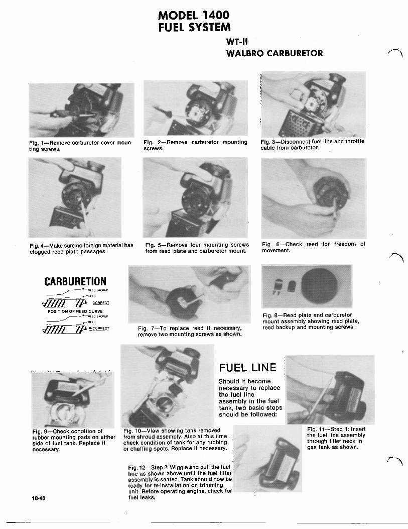
M O D E L 1400 FUEL SYSTEM
WT-II WALBRO CARBURETOR
Fig. l-Remove carburetor cover moun- Fig. 2-Remove carburetor mounting Fig. 3-Disconnect fuel line and throttle ting screws. screws. cable from carburetor.
Fig. 4-Make sure no foreign material has Fig. 5-Remove four mounting screws Fig. 6-Check reed for freedom of clogged reed plate passages. from reed plate and carburetor mount. movement.
Fig. 9-Check condition of rubber mounting pads on either side of fuel tank. Replace if necessary.
18-48 fuel leaks.
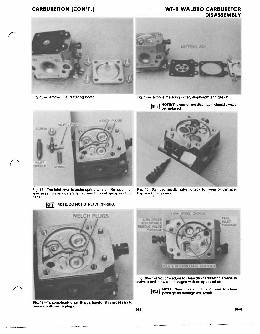
CARBURETION (CON'T.) WT-II WALBRO CARBURETOR DISASSEMBLY
Fig. 13-Remove Fuel Metering cover.
NOTE: The gasket and diaphragm should always be replaced.
Fig. 15-The inlet lever is under spring tension. Remove inlet lever assembly very carefully to prevent loss of spring or other parts.
NOTE DO NOT STRETCH SPRING.
Fig. 16-Remove needle valve. Check for wear or damage. Replace i f necessary.
Fig. 18-Correct procedure to clean this carburetor is wash in solvent and blow all passages with compressed air.
NOTE Never use drill bits or wire to clean passage as damage will result.
Fig. 17-To completely clean this carburetor, it is necessary to remove both welch plugs.
1983 I983 18-49
CARBURETION (CONT'D.) WT-II WALBRO CARBURETOR DISASSEMBLY
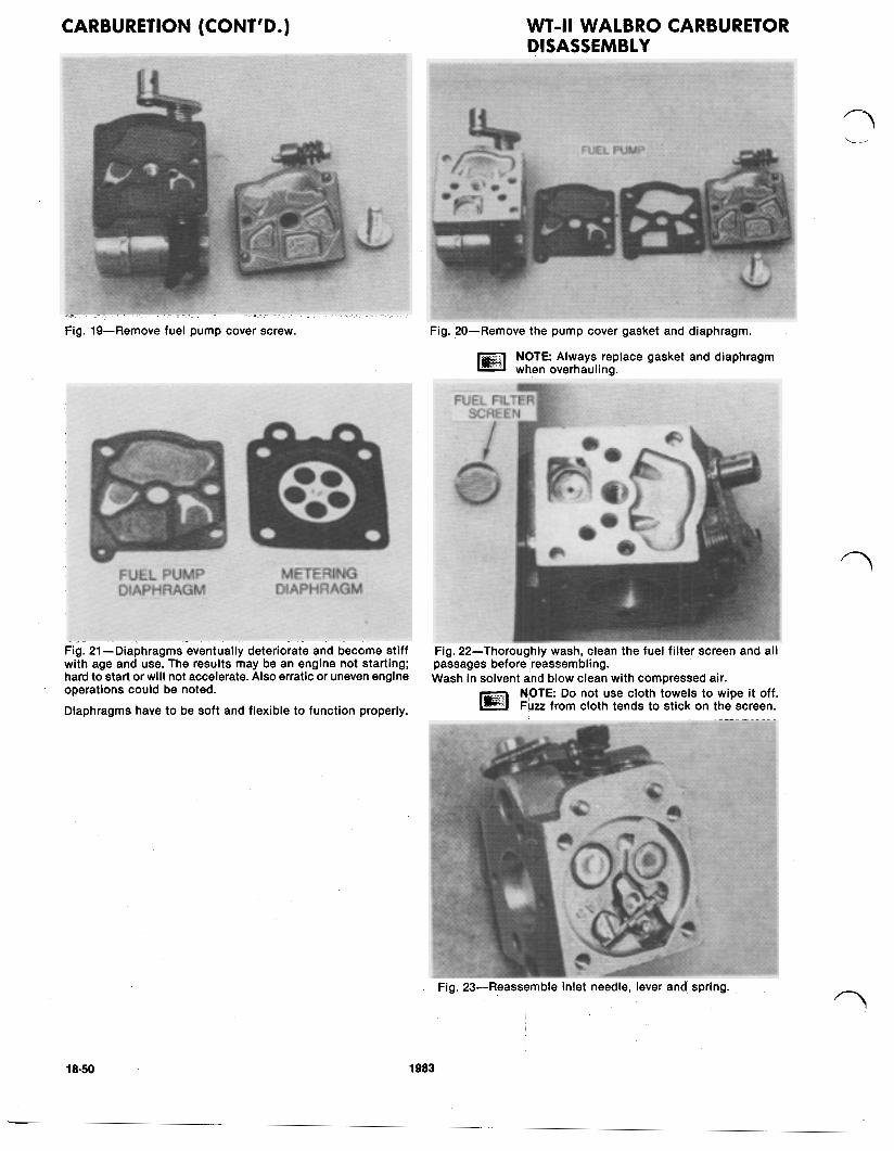
Fig. 19-Remove fuel pump cover screw. Fig. 20-Remove the pump cover gasket and diaphragm.
NOTE Always replace gasket and diaphragm when overhauling.
Fig. 21-Diaphragms eventually deteriorate and become stiff with age and use. The results may be an engine not starting; hard to start or will not accelerate. Also erratic or uneven engine operations could be noted. Diaphragms have to be soft and flexible to function properly.
Fig. 22-Thoroughly wash, clean the fuel filter screen and all passages before 'reassembling. Wash in solvent and blow clean with compressed air.
NOTE Do not use cloth towels to wipe it off. Fuzz from cloth tends to stick on the screen.
Fig. 23-Reassemble inlet needle, lever and spring.
18-50 1983
CARBURETION (CONT'D.) WT-II WALBRO REASSEMBLY
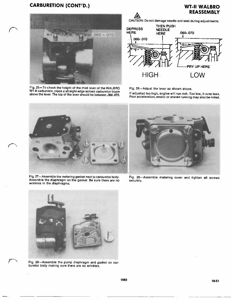
CAUTION Do not damage needle and seat during adjustments.
DEPRESS THEN PUSH
HERE NEEDLE HERE 060-070 \ .0,60-.070 I
HIGH LOW
Fig. 27-Assemble the metering gasket next to carburetor body. Fig. 28-Assemble metering cover and tighten all screws Assemble the diaphragm on the gasket. Be sure there are no securely. wrinkles in the diaphragms.
Fig. 29-Assemble the pump diaphragm and gasket on car- buretor body making sure there are no wrinkles.
1983 18-51
CARBURETION (CONT'D.)
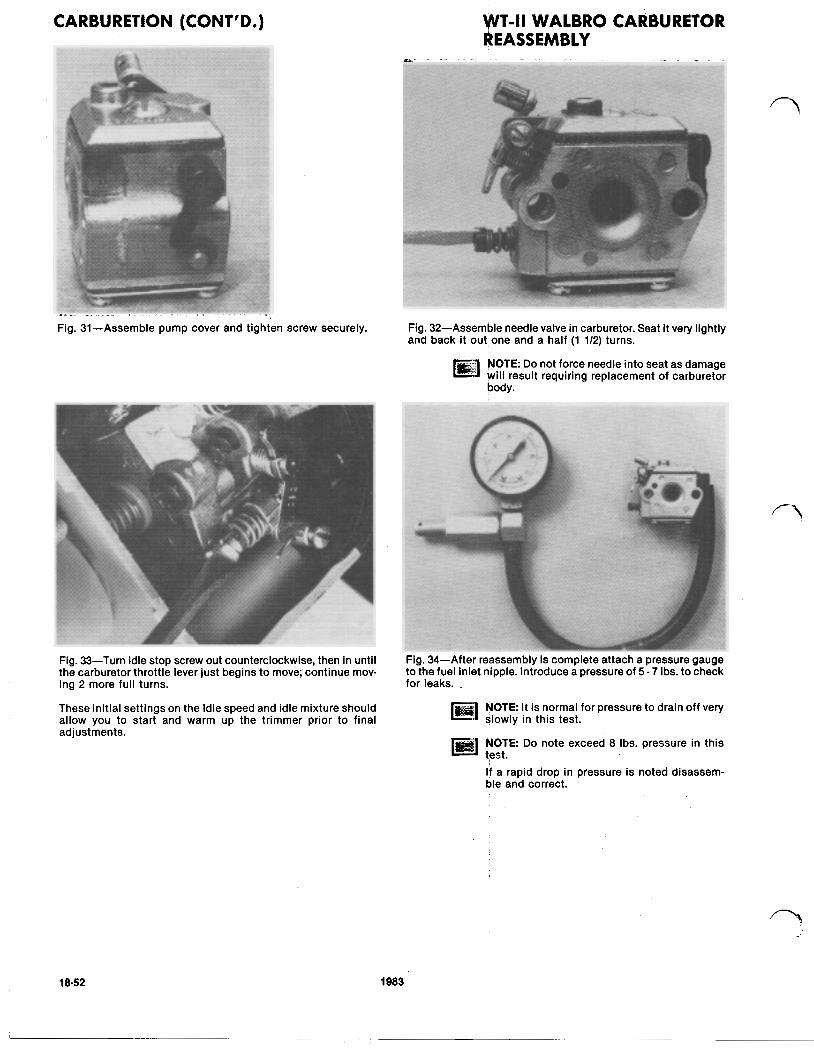
Fig. 31-Assemble pump cover and tighten screw securely.
WT-ll WALBRO CARBURETOR REASSEMBLY
Fig. 32-Assemble needle valve in carburetor. Seat it very lightly and back it out one and a half (1 112) turns.
NOTE Do not force needle into seat as damage will result requiring replacement of carburetor body.
Fig. 33-Turn idle stop screw out counterclockwise, then in until the carburetor throttle lever just begins to move; continue mov- ing 2 more full turns.
These initial settings on the Idle speed and idle mixture should allow you to start and warm up the trimmer prior to final adjustments.
Fig. 34-Af ter reassembly is complete attach a pressure gauge to the fuel inlet nipple. Introduce a pressure of 5 7 Ibs. to check for leaks.
N O T E It is normal for pressure to drain off very slowly in this test.
NOTE Do note exceed 8 Ibs. pressure in this test. If a rapid drop in pressure is noted disassem- ble and correct.
18-52 1983
CARBURETION (CONT'D) M O D E L 1460 TRIMMER
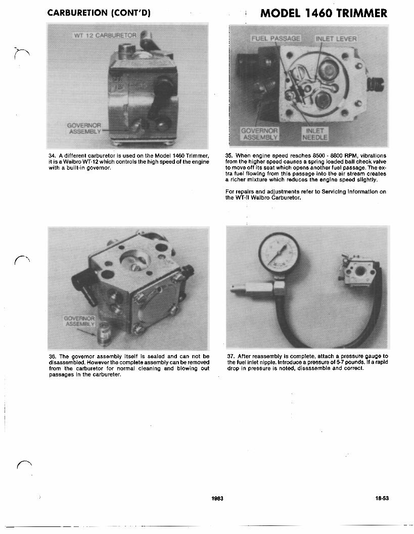
34. A different carburetor is used on the Model 1460 Trimmer, it is a Walbro WT-12 which controls the high speed of the engine with a built-in governor.
36. The governor assembly itself Is sealed and can not be disassembled. However the complete assembly can be removed from the carburetor for normal cleaning and blowing out passages in the carbureteor.
35. When engine speed reaches 8500 8800 RPM, vibrations from the higher speed causes a spring loaded ball check valve to move off its seat which opens another fuel passage. The ex- tra fuel flowing from this passage into the air stream creates a richer mixture which reduces the engine speed slightly.
For repairs and adjustments refer to Servicing Information on the WT-ll Walbro Carburetor.
37. After reassembly i s complete, attach a pressure gauge to the fuel inlet nipple. Introduce a pressure of 5-7 pounds. If a rapid drop in pressure is noted, disassemble and correct.
1983 18-53
STARTING WALBRO CARBURETOR REASSEMBLY, TESTING AND ADJUSTMENTS
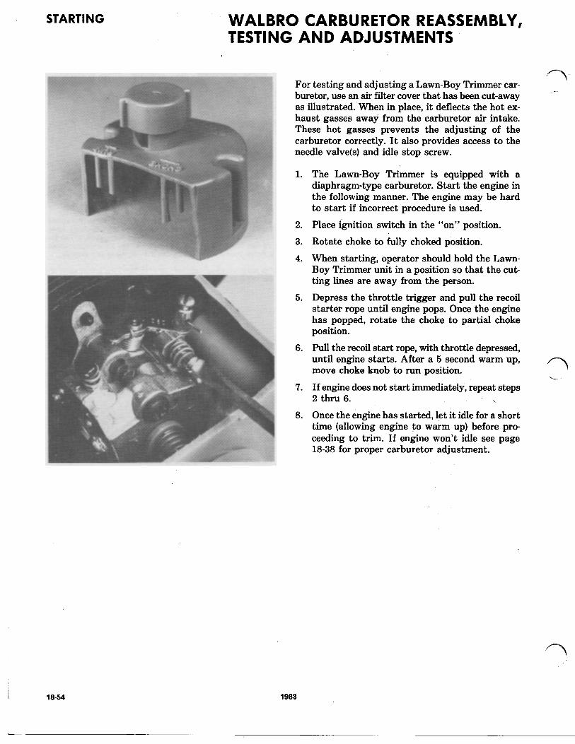
?- For testing and adjusting a Lawn-Boy Trimmer car- buretor, use an air filter cover that has been cut-away as illustrated. When in place, it deflects the hot ex- haust gasses away from the carburetor air intake. These hot gasses prevents the adjusting of the carburetor correctly. It also provides access to the needle valve(s) and idle stop screw.
1.
2.
3.
4.
5.
6.
7.
8.
The Lawn-Boy Trimmer is equipped with a diaphragm-type carburetor. Start the engine in the following manner. The engine may be hard to start if incorrect procedure is used.
Place ignition switch in the “on” position.
Rotate choke to fully choked position.
When starting, operator should hold the Lawn- Boy Trimmer unit in a position so that the cut- ting lines are away from the person.
Depress the throttle trigger and pull the recoil starter rope until engine pops. Once the engine has popped, rotate the choke to partial choke position.
pull the’ recoil start rope, with throttle depressed, until engine starts. After a 5 second warm up, move choke knob to run position.
If engine does not start immediately, repeat steps 2 thru 6 . . Once the engine has started, let it idle for a short time (allowing engine to warm up) before pro- ceeding to trim. If engine won’t idle see page 18-38 for proper carburetor adjustment.
18-54 1983
![Z1, Short form service- repair guide - Classic Kawasaki Sweden1].pdf · Fig. K13-3ÆxplOded view of carburetor used on 903cc Kawasaki. MAINTENANCE ... plug electrode gap should be](https://img.pdfslide.net/doc/110x75/5c969dc309d3f2650d8c9fdd/z1-short-form-service-repair-guide-classic-kawasaki-1pdf-fig-k13-3axploded.jpg)