Embed Size (px)
Citation preview
Cardiff Airport RNAV Replications
Airspace Change Proposal
Issue 2 April 2015 Prepared by:
Manager Operations and Training NATS Cardiff On Behalf of Cardiff International Airport Limited

Issue Log
Issue number Date Description
1.0 30/04/2015 Initial issue to CAA SARG
Table of contents Table of contents ..................................................................................................................................................... 3
1. Introduction .................................................................................................................................................... 6
2. Justification .................................................................................................................................................... 7
3. Current Airspace Description ......................................................................................................................... 8
4. Proposed Airspace Description .................................................................................................................... 17
5. Impacts Summary ......................................................................................................................................... 21
6. Consultation ................................................................................................................................................. 25
7. Analysis of Options ...................................................................................................................................... 27
8. Airspace Description Requirement ............................................................................................................... 28
9. Operational Impact ....................................................................................................................................... 30
10. Supporting Infrastructure & Resources .................................................................................................... 31
11. Airspace & Infrastructure Requirements ................................................................................................. 32
12. Environmental Requirements ................................................................................................................... 35
Appendices .......................................................................................................................................................... 44
Appendix A: Cardiff Standard Terminal ARrival Charts ............................................................................ 44
Appendix B: Cardiff CTR & CTA Chart ....................................................................................................... 48
Appendix C: Elements of the Y-Bar and T-Bar .......................................................................................... 49
Appendix D: Proposed Amendments to the AIP ........................................................................................ 50
Appendix E: Flight Validation Plan ............................................................................................................... 51
Appendix F: Consultation Feedback report ................................................................................................ 52

Intentionally Blank
Section Summary
Sections 1 and 2 offer an Introduction to the project and Justification for the use of RNAV, detailing the benefits of its use. Section 3 gives the Current Airspace Description including maps of the current aircraft tracks with indicative inbound descent heights. Numbers and types of aircraft using the airport are also given along with predicted traffic growth. Section 4 details the Proposed Airspace Description, detailing the RNAV design elements and the proposed inbound tracks and heights for both runways. Section 5 details the Impacts on safety, the environment and other airspace users. Section 6 outlines the Consultation, the list of invited consultees, the methods of engagement and the responses received. It points to the Post Consultation Feedback Report for a more detailed discussion on the consultation. Section 7, Analysis of Options, details other proposals which were considered and discounted as part of the design process. Sections 8 to 12 detail the CAP725 requirements in the respective areas of, Airspace Description Requirement, Operational Impact, Supporting Infrastructure & Resources, Airspace & Infrastructure Requirements and
Environmental Requirements. The Appendices contain the current and proposed approach procedures and CTR/CTA Charts, noise contours, the elements which make up the T bar of an RNAV approach and the Proposed Amendments to the AIP following the change. The Flight Validation Plan and the Post Consultation Feedback Report are also included.
1. Introduction This document has been produced by NATS on behalf of Cardiff International Airport Limited (CIAL). CIAL is the sponsor of this change and any queries regarding this Airspace Change Proposal (ACP) should be directed to CIAL in the first instance. This document details CIAL’s compliance with CAP725 requirements regarding this ACP. The purpose of the proposed airspace change is to replicate the current conventional tracks of aircraft arriving at Cardiff Airport for Runways 12 and 30. The replicated tracks will be more accurately defined utilising the improved navigational capabilities of modern aircraft (Area Navigation: RNAV) and will initially be used in parallel with existing conventional Instrument Approach Procedures. This will enable continued accessibility for those aircraft not RNAV equipped. The improved track-keeping ability of RNAV should, over time, result in less lateral dispersal of flights either side of the inbound routes. Thus overall, fewer people will experience overflying aircraft. However those who are directly beneath the flight path are likely to experience a greater number of aircraft over-flights. CIAL is planning to implement the changes detailed in this proposal on 10th December 2015 (AIRAC 13/2015). The consultation for this proposal, managed by CIAL, ran from 16th December 2014 until 24th March 2015, the results of which are summarised in a post-consultation feedback report (see Appendix F).
2. Justification This proposal aims to replicate, as closely as possible, current aircraft approach tracks through the use of new RNAV routes. It is not the intention to introduce new aircraft tracks but rather to enable aircraft to fly their existing tracks more accurately, keeping to broadly similar speeds and heights over the ground. RNAV routes will enable more consistent use of efficient descent profiles (continuous descent approaches – CDAs) and should subsequently deliver noise and emissions benefits. Area Navigation (RNAV) enables aircraft to control their position with far greater accuracy than conventional forms of navigation. Hence the aircraft’s position is known with greater certainty, and when operating under “own navigation” Air Traffic Control (ATC) have much greater certainty that aircraft are conforming to the defined RNAV routes, within close tolerances. Since aircraft will follow RNAV approaches with greater accuracy, they will be allowed to self-navigate to a greater extent than is the case for those following conventional approaches. Hence the number of tactical interventions (radio calls) from the air traffic controllers will be reduced. In congested airspace, this aids efficiency, expedition and safety. The capabilities and benefits of the RNAV navigation specification are well documented. The background for this change includes the stated CAA policy for adoption of RNAV in UK airspace which has already been subject to a separate consultation by the UK CAA (SARG) and is a cornerstone of the UK Government’s Future Airspace Strategy (FAS)1, which recommends the transition to performance based navigation (PBN) technologies, of which RNAV is a part. The change is supported by the airlines for the following reasons:
- Procedures designed to PBN specifications allow airlines to use their FMS equipment to its full capability to assure predictable flights paths
- More predictable flight planning
- Improved standardisation of flight profiles in accordance with standard operational procedures. This improves predictability, which enables the crew to plan the descent with more certainty and achieve a more efficient descent profile
- The move away from reliance on ground based navigation aids
1 CAA Future Airspace Strategy Deployment Plan, Iteration Three, Version 1.2, December 2012. Chapter C1 PBN Implementation
3. Current Airspace Description
3.1 Arrival Routes
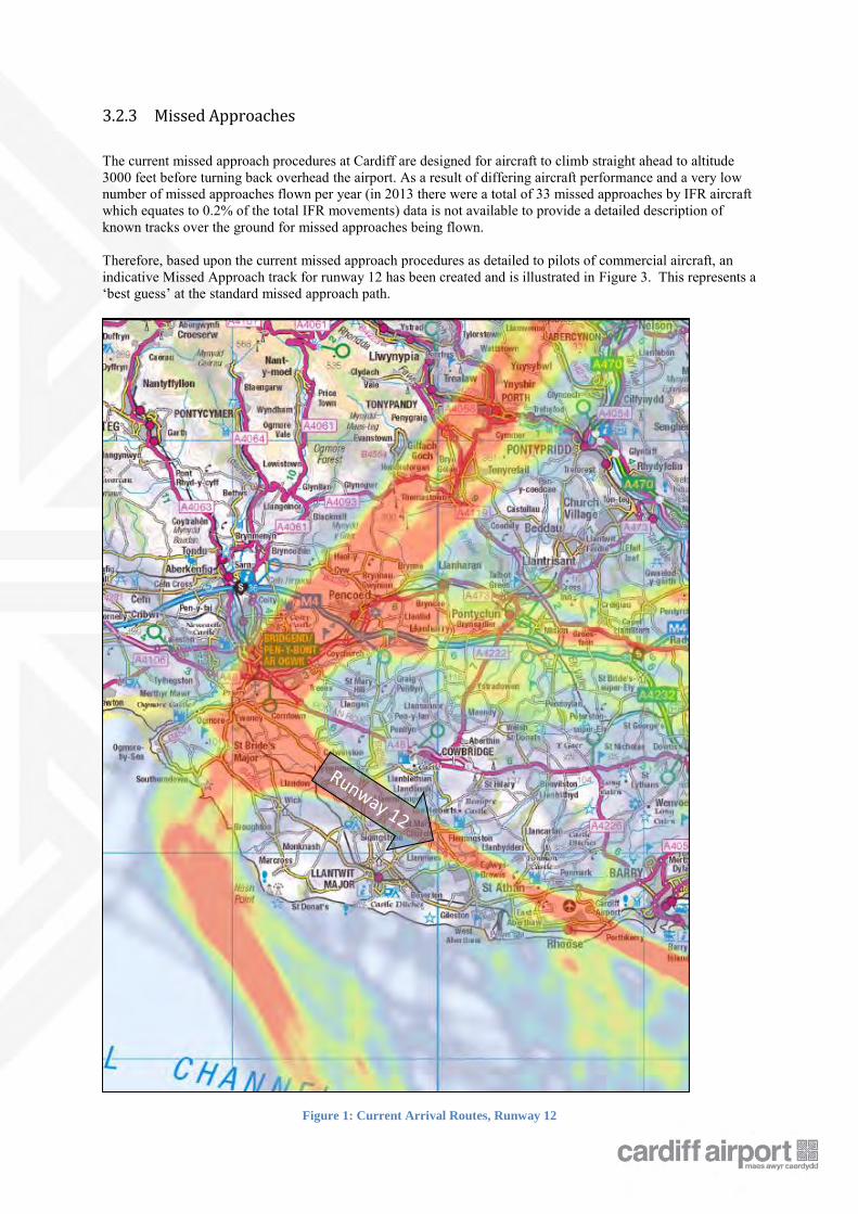
The Cardiff Airport runway is aligned south-east / north-west. The north westerly runway is designated as runway 30 as aircraft landing on or taking off from the runway will be facing a magnetic compass heading of 300° whilst the south easterly runway is designated runway 12 (aircraft on that runway facing 120°). Aircraft arrive at Cardiff airport via 5 published STARs (Standard Terminal Arrival Routes – See Appendix A: Cardiff Standard Terminal ARrival Charts) which take the aircraft to overhead Cardiff airport. From here aircraft will then fly one of the Cardiff Airport IAPs (Instrument Approach Procedures) to land. In practice nearly every flight is directed by radar on tactical headings to fly away from these routes to final approach. This is illustrated in the trajectory density plots of Figure 1 for Runway 12 and Figure 4 for Runway 30 (traffic samples illustrated are taken from the month of July 2013). Density plots are colour coded with the highest density of aircraft represented in red and lower numbers of aircraft represented in yellow, green and grey for just one or two tracks. The main routes which aircraft currently take to each runway can be seen in the density plots of Figure 1 and Figure 4, with the yellow and grey ‘paths’ (for instance in the Llantwit Major area) indicating the dispersal of aircraft along the red centre track. This demonstrates how tactical intervention by Air Traffic Control creates a spread of tracks flown. The proposed RNAV routes are designed to replicate the existing track concentrations (red tracks in Figure 1 & Figure 4). The introduction of the proposed RNAV routings will not introduce new aircraft tracks in areas that are not currently being overflown. It is anticipated that initially there will be very little change in the spread of tracks as flown today. However as aircraft fleets are updated with RNAV navigation systems and as the airlines and their crews adopt RNAV operating procedures, the dispersed pattern of traffic is likely to reduce and become concentrated in the centre of the tracks. The heights of aircraft utilising RNAV approaches should increase slightly when considered along the entire approach path, with improved descent planning delivering increased and improved CDAs (over those achieved by tactically vectored aircraft today).
3.2 Runway 12
3.2.1 Current Aircraft Tracks
Common routes can be seen in Figure 1 which take aircraft from the north and south and position them for final approach to runway 12. However at times it can also be seen that many flights take more direct routings, thus broadening the approach path from each direction. These tactical direct routings are expected to remain for some time after the introduction of the RNAV routes, especially at times of low traffic density and before the volume of suitably equipped aircraft increases. .
3.2.2 Current Aircraft Heights
Current aircraft height bands are indicated in Figure 2 which shows the descent profiles along the highest track concentration. The extremes of the bands indicate the lowest and highest inbound aircraft within that band and each banding is bounded 500ft higher and lower than the figure covered e.g. 4000 feet means 3500 feet to 4499 Feet. Aircraft following an RNAV track and executing a CDA will maintain similar inbound levels to one another and these are anticipated to be, on average, slightly higher than those of today, however the proposed change is not predicated on an increase in average aircraft height or subsequently reduced aircraft noise.
3.2.3 Missed Approaches
The current missed approach procedures at Cardiff are designed for aircraft to climb straight ahead to altitude 3000 feet before turning back overhead the airport. As a result of differing aircraft performance and a very low number of missed approaches flown per year (in 2013 there were a total of 33 missed approaches by IFR aircraft which equates to 0.2% of the total IFR movements) data is not available to provide a detailed description of known tracks over the ground for missed approaches being flown. Therefore, based upon the current missed approach procedures as detailed to pilots of commercial aircraft, an indicative Missed Approach track for runway 12 has been created and is illustrated in Figure 3. This represents a ‘best guess’ at the standard missed approach path.
Figure 1: Current Arrival Routes, Runway 12
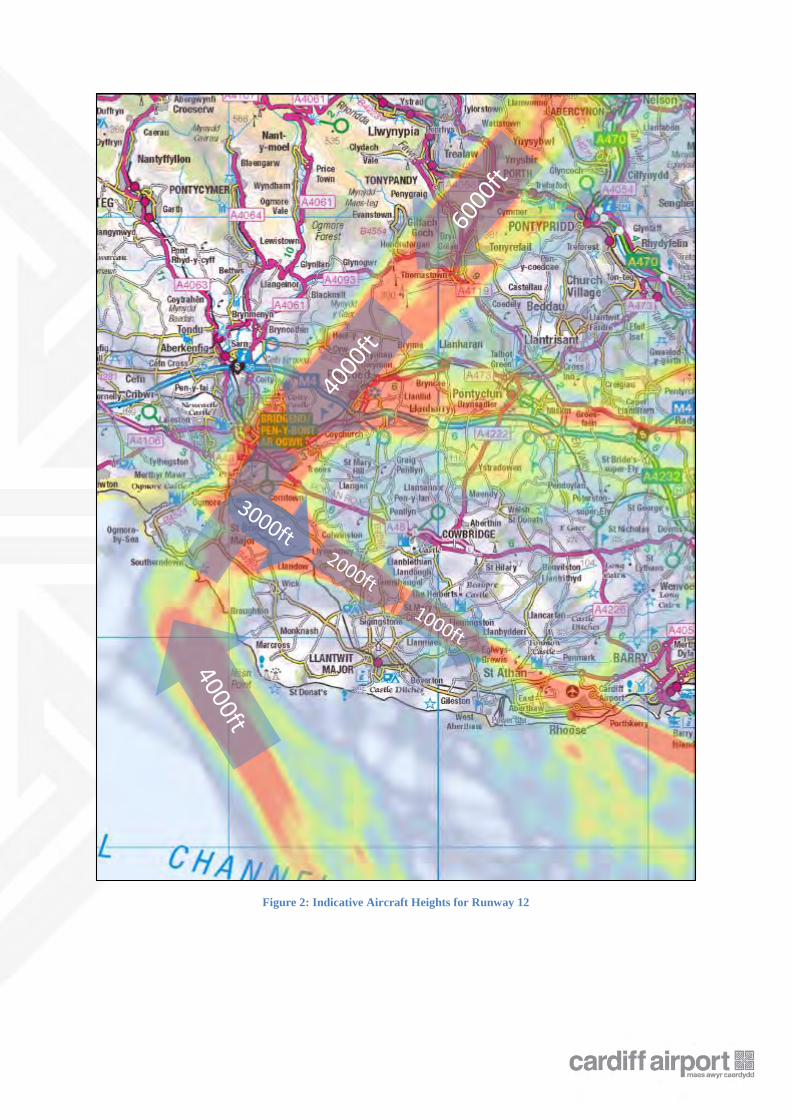
Figure 2: Indicative Aircraft Heights for Runway 12
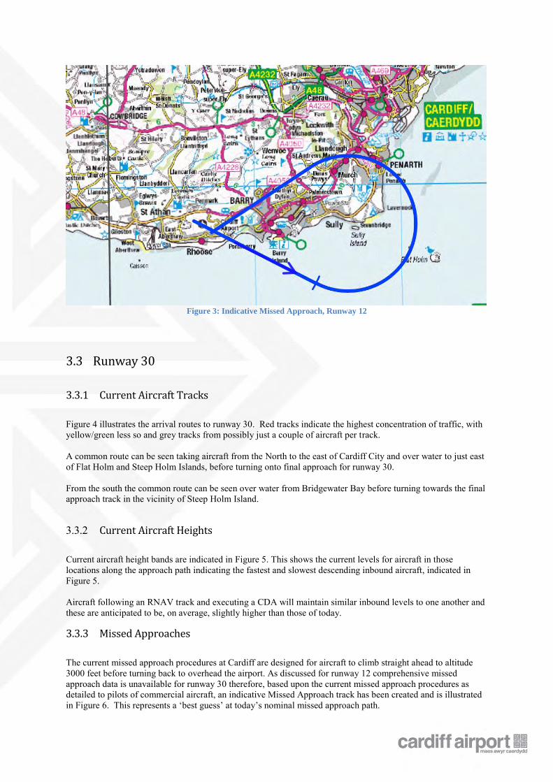
Figure 3: Indicative Missed Approach, Runway 12
3.3 Runway 30
3.3.1 Current Aircraft Tracks
Figure 4 illustrates the arrival routes to runway 30. Red tracks indicate the highest concentration of traffic, with yellow/green less so and grey tracks from possibly just a couple of aircraft per track. A common route can be seen taking aircraft from the North to the east of Cardiff City and over water to just east of Flat Holm and Steep Holm Islands, before turning onto final approach for runway 30. From the south the common route can be seen over water from Bridgewater Bay before turning towards the final approach track in the vicinity of Steep Holm Island.
3.3.2 Current Aircraft Heights
Current aircraft height bands are indicated in Figure 5. This shows the current levels for aircraft in those locations along the approach path indicating the fastest and slowest descending inbound aircraft, indicated in Figure 5. Aircraft following an RNAV track and executing a CDA will maintain similar inbound levels to one another and these are anticipated to be, on average, slightly higher than those of today.
3.3.3 Missed Approaches
The current missed approach procedures at Cardiff are designed for aircraft to climb straight ahead to altitude 3000 feet before turning back to overhead the airport. As discussed for runway 12 comprehensive missed approach data is unavailable for runway 30 therefore, based upon the current missed approach procedures as detailed to pilots of commercial aircraft, an indicative Missed Approach track has been created and is illustrated in Figure 6. This represents a ‘best guess’ at today’s nominal missed approach path.
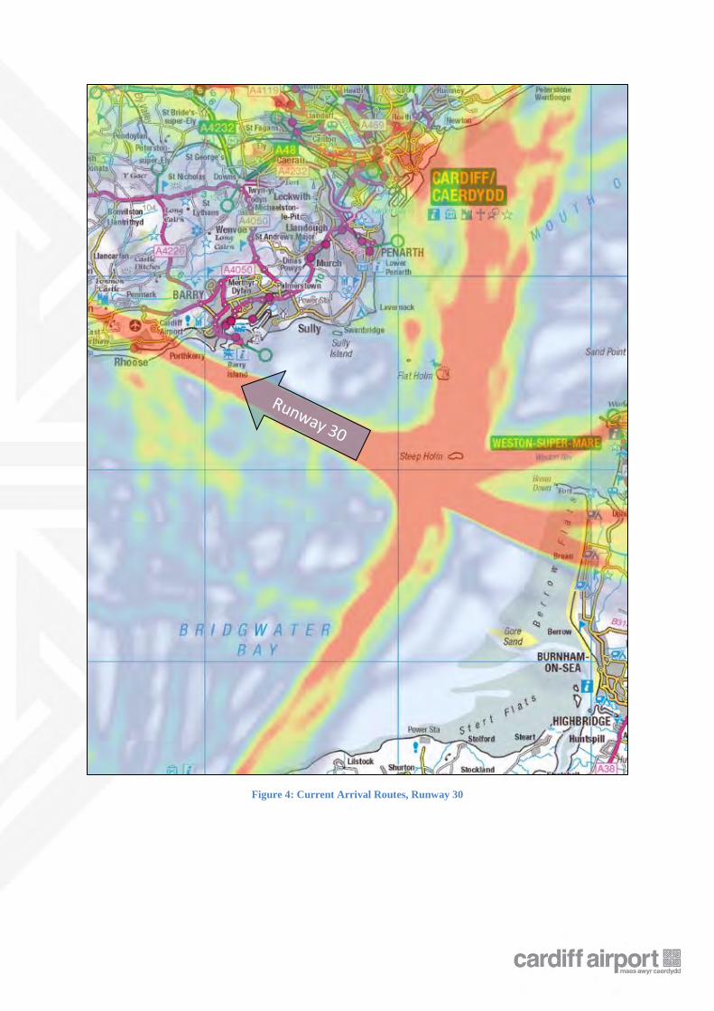
Figure 4: Current Arrival Routes, Runway 30
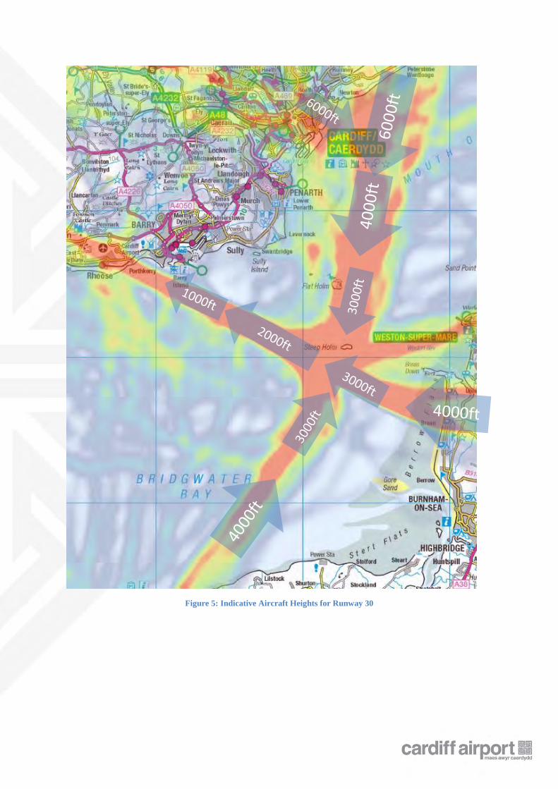
Figure 5: Indicative Aircraft Heights for Runway 30
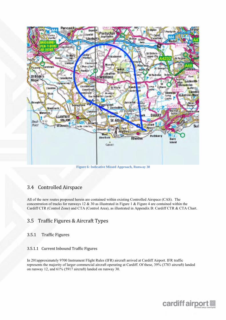
Figure 6: Indicative Missed Approach, Runway 30
3.4 Controlled Airspace
All of the new routes proposed herein are contained within existing Controlled Airspace (CAS). The concentration of tracks for runways 12 & 30 as illustrated in Figure 1 & Figure 4 are contained within the Cardiff CTR (Control Zone) and CTA (Control Area), as illustrated in Appendix B: Cardiff CTR & CTA Chart.
3.5 Traffic Figures & Aircraft Types
3.5.1 Traffic Figures
3.5.1.1 Current Inbound Traffic Figures
In 201approximately 9700 Instrument Flight Rules (IFR) aircraft arrived at Cardiff Airport. IFR traffic represents the majority of larger commercial aircraft operating at Cardiff. Of these, 39% (3783 aircraft) landed on runway 12, and 61% (5917 aircraft) landed on runway 30.
3.5.1.2 Predicted Inbound Traffic Growth
The introduction of RNAV STARs will not influence the rate of growth of traffic operating into Cardiff airport. NATS forecast traffic growth figures are given in Table 1 and illustrate inbound figures only. Starting with the 2014 figures as a baseline, they have been grown for the predicted Year of implementation (2015) and five years after that (2020).
Year 2014 2015 (+8%)
2020 (+22%)
Total Traffic 9694 10470 11826
Table 1: Predicted Traffic Growth
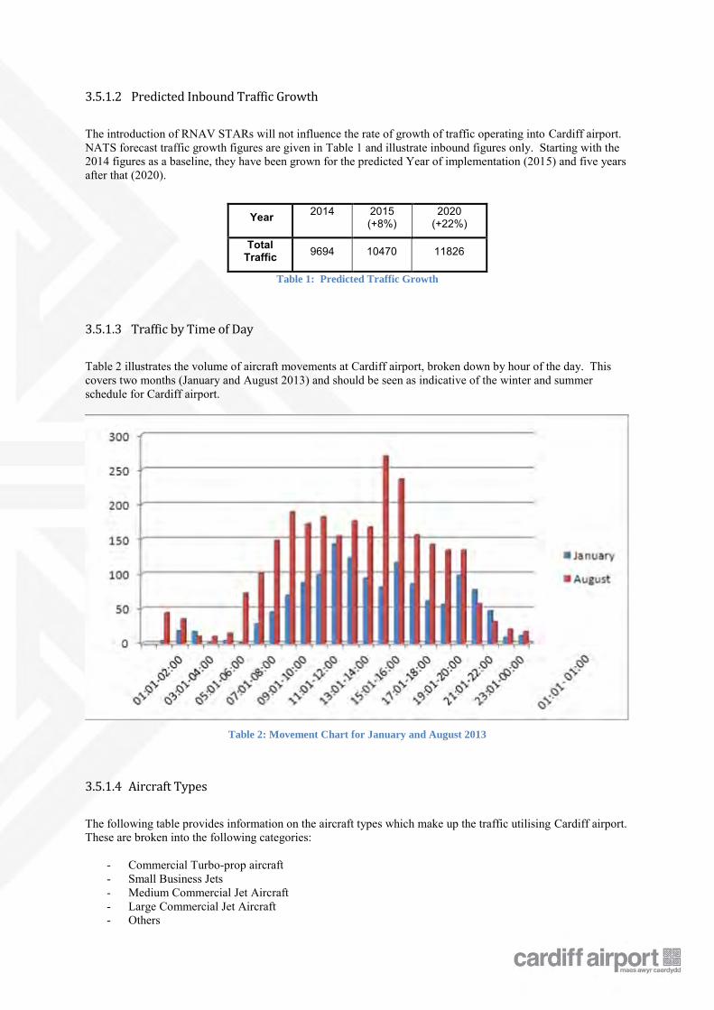
3.5.1.3 Traffic by Time of Day
Table 2 illustrates the volume of aircraft movements at Cardiff airport, broken down by hour of the day. This covers two months (January and August 2013) and should be seen as indicative of the winter and summer schedule for Cardiff airport.
Table 2: Movement Chart for January and August 2013
3.5.1.4 Aircraft Types
The following table provides information on the aircraft types which make up the traffic utilising Cardiff airport. These are broken into the following categories:
- Commercial Turbo-prop aircraft - Small Business Jets - Medium Commercial Jet Aircraft - Large Commercial Jet Aircraft - Others
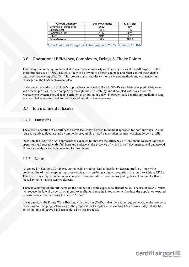
Aircraft Category Total Movements % of Total Commercial Turbo-prop 3682 38% Business Jet 354 4% Commercial Jet 4417 45% Others 1241 13% Total Arrivals 9694 100%
Table 3: Aircraft Categories & Percentage of Traffic Numbers for 2014
3.6 Operational Efficiency, Complexity, Delays & Choke Points
This change is not being implemented to overcome complexity or efficiency issues at Cardiff airport. In the short term the use of RNAV routes is likely to be low until aircraft equipage and radar control tools enable improved sequencing of traffic. This proposal is an enabler to future working methods and efficiencies as envisaged in the FAS deployment plan. In the longer term the use of RNAV approaches connected to RNAV STARs should deliver predictable routes and descent profiles, reduce complexity through this predictability and if coupled with say an Arrival Management system, should enable efficient distribution of delay. However these benefits are medium to long term enabled aspirations and are not factored into this change proposal.
3.7 Environmental Issues
3.7.1 Emissions
The current operation at Cardiff sees aircraft tactically vectored to the final approach for both runways. As the route is variable, albeit around a commonly used track, aircraft cannot plan the most efficient descent profile. Over time the use of RNAV approaches is expected to improve the efficiency of Continuous Descent Approach operations and subsequently fuel burn and emissions, the evidence of which is well documented and understood. No further analysis will be conducted for this change.
3.7.2 Noise
As covered in Section 3.7.1 above, unpredictable routings lead to inefficient descent profiles. Improving predictability of track keeping improves efficiency by enabling a higher proportion of aircraft to achieve CDAs. This also brings improvement in noise impact, since aircraft in a continuous gliding descent are quieter than those having to make a stepped descent. Tactical vectoring of aircraft increases the number of people exposed to aircraft noise. The use of RNAV routes will reduce the lateral dispersal of aircraft over-flights; hence its introduction will reduce the population exposed to noise from aircraft arriving to Cardiff Airport. It was agreed at the Frame Work Briefing with the CAA (SARG), that there is no requirement to undertake noise modelling for this proposal so long as the proposed tracks replicate the existing tracks flown today. It is CIALs belief that this objective has been achieved by this proposal.
4. Proposed Airspace Description
4.1 Objectives/Requirements for Proposal
The objective of this proposal is to introduce RNAV Instrument Approach Procedures to replicate the tracks which aircraft currently fly over the ground today, enabling improved track keeping and CDA performance for the future. These will be introduced coincident with the current IAPs so that all aircraft, whether RNAV equipped or not, may continue to utilise Cardiff airport. This does not preclude ATC from directing aircraft tactically, on an individual basis and routing them directly to final approach, as today. ATC may do this from any point along the RNAV approach path – this is used to ensure safe separation is maintained, optimise time and space on the final approach, and to reduce the track distance flown by arriving aircraft where possible. The proposal should not alter the airspace buffer arrangements between Cardiff and Bristol ATCUs which allows autonomous radar operations. The Buffer allows controllers at both airports to utilise 3NM radar separation by creating a ‘buffer zone’ between the two units where no controller shall enter without speaking with the other unit. These procedures are designed to provide as much flexible use of the airspace as is possible, to achieve a safe and expeditious flow of air traffic between the two airports.
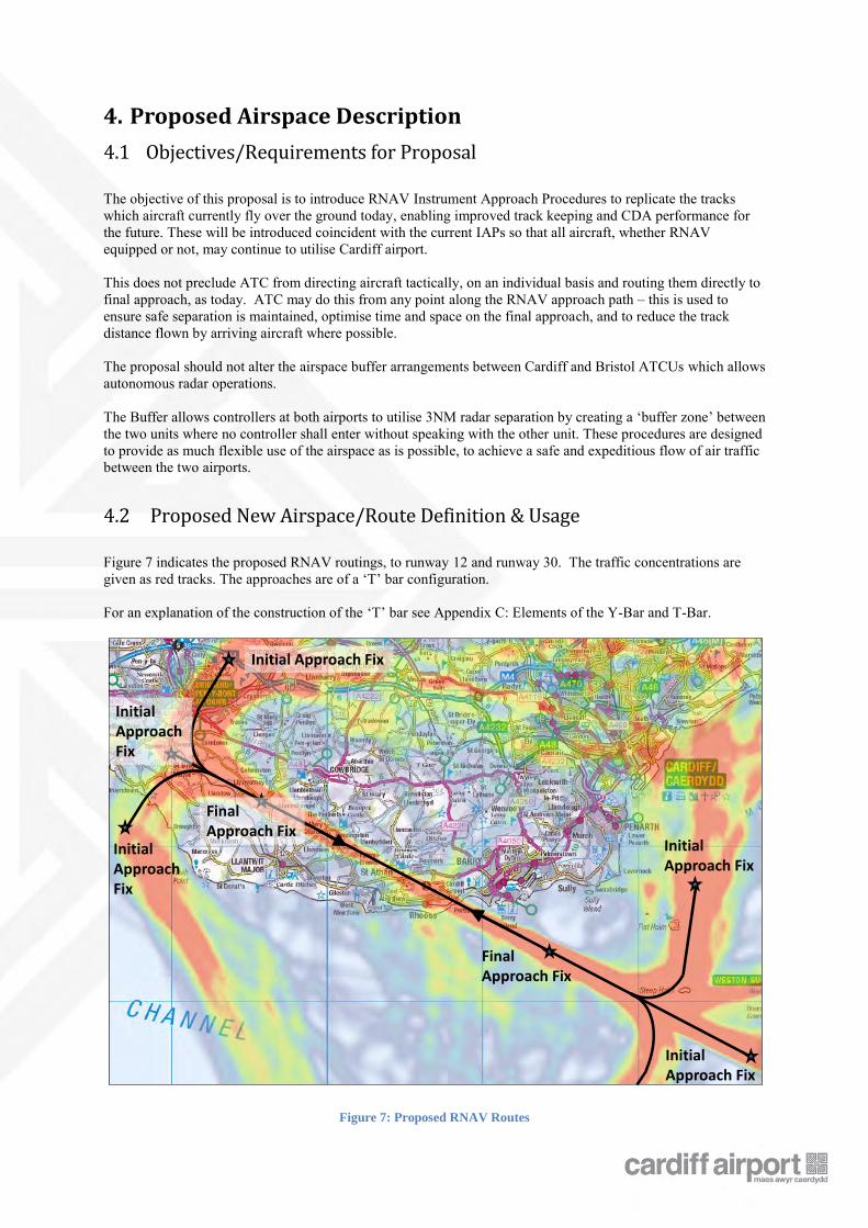
4.2 Proposed New Airspace/Route Definition & Usage
Figure 7 indicates the proposed RNAV routings, to runway 12 and runway 30. The traffic concentrations are given as red tracks. The approaches are of a ‘T’ bar configuration. For an explanation of the construction of the ‘T’ bar see Appendix C: Elements of the Y-Bar and T-Bar.
Figure 7: Proposed RNAV Routes
Final Approach Fix
Final Approach Fix
Initial Approach Fix
Initial Approach Fix
Initial Approach Fix
Initial Approach Fix
Initial Approach Fix
4.2.1 Runway 12 Approach
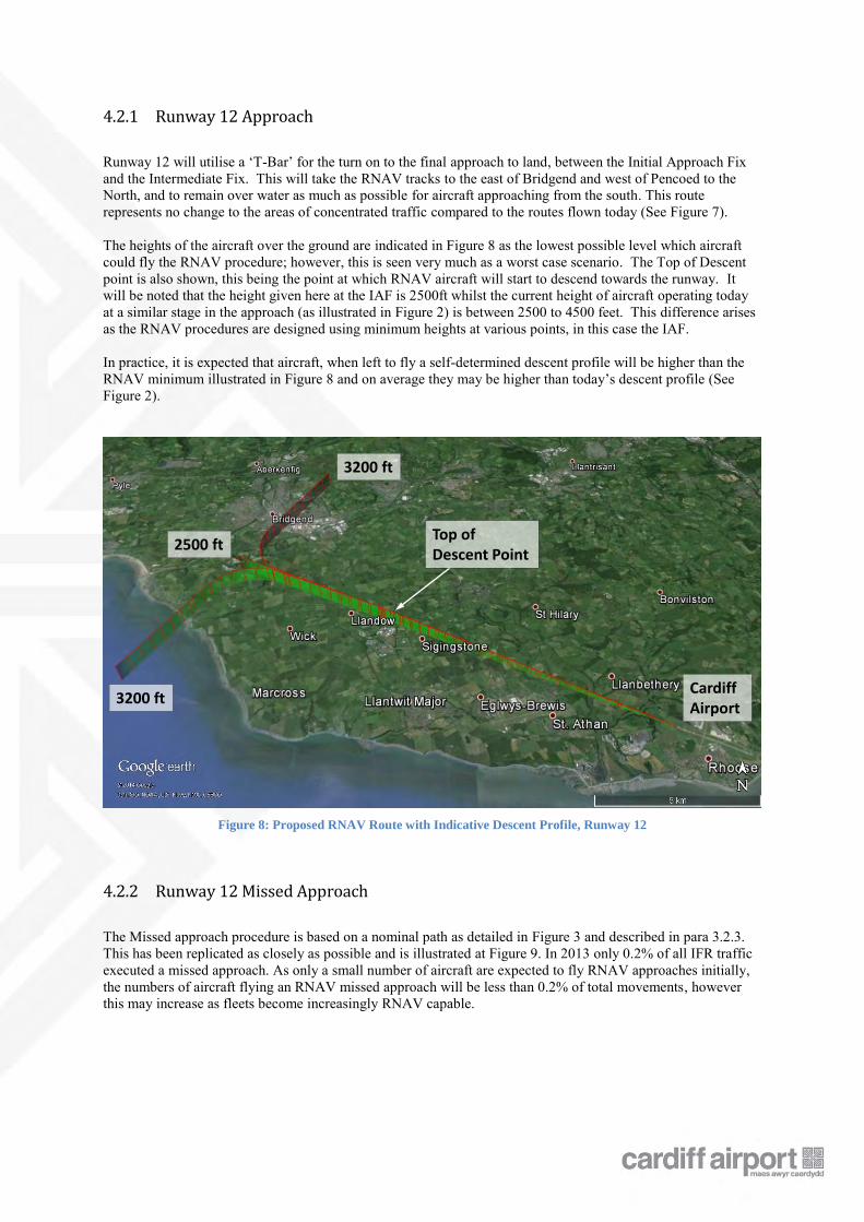
Runway 12 will utilise a ‘T-Bar’ for the turn on to the final approach to land, between the Initial Approach Fix and the Intermediate Fix. This will take the RNAV tracks to the east of Bridgend and west of Pencoed to the North, and to remain over water as much as possible for aircraft approaching from the south. This route represents no change to the areas of concentrated traffic compared to the routes flown today (See Figure 7). The heights of the aircraft over the ground are indicated in Figure 8 as the lowest possible level which aircraft could fly the RNAV procedure; however, this is seen very much as a worst case scenario. The Top of Descent point is also shown, this being the point at which RNAV aircraft will start to descend towards the runway. It will be noted that the height given here at the IAF is 2500ft whilst the current height of aircraft operating today at a similar stage in the approach (as illustrated in Figure 2) is between 2500 to 4500 feet. This difference arises as the RNAV procedures are designed using minimum heights at various points, in this case the IAF. In practice, it is expected that aircraft, when left to fly a self-determined descent profile will be higher than the RNAV minimum illustrated in Figure 8 and on average they may be higher than today’s descent profile (See Figure 2).
Figure 8: Proposed RNAV Route with Indicative Descent Profile, Runway 12
4.2.2 Runway 12 Missed Approach
The Missed approach procedure is based on a nominal path as detailed in Figure 3 and described in para 3.2.3. This has been replicated as closely as possible and is illustrated at Figure 9. In 2013 only 0.2% of all IFR traffic executed a missed approach. As only a small number of aircraft are expected to fly RNAV approaches initially, the numbers of aircraft flying an RNAV missed approach will be less than 0.2% of total movements, however this may increase as fleets become increasingly RNAV capable.
3200 ft
2500 ft
3200 ftCardiff Airport
Top of Descent Point
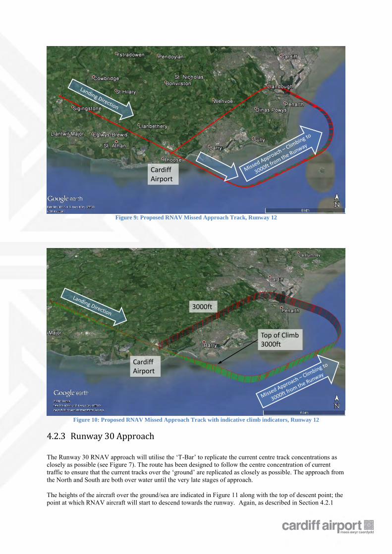
Figure 9: Proposed RNAV Missed Approach Track, Runway 12
Figure 10: Proposed RNAV Missed Approach Track with indicative climb indicators, Runway 12
4.2.3 Runway 30 Approach
The Runway 30 RNAV approach will utilise the ‘T-Bar’ to replicate the current centre track concentrations as closely as possible (see Figure 7). The route has been designed to follow the centre concentration of current traffic to ensure that the current tracks over the ‘ground’ are replicated as closely as possible. The approach from the North and South are both over water until the very late stages of approach. The heights of the aircraft over the ground/sea are indicated in Figure 11 along with the top of descent point; the point at which RNAV aircraft will start to descend towards the runway. Again, as described in Section 4.2.1
Cardiff Airport
Cardiff Airport
Top of Climb3000ft
3000ft
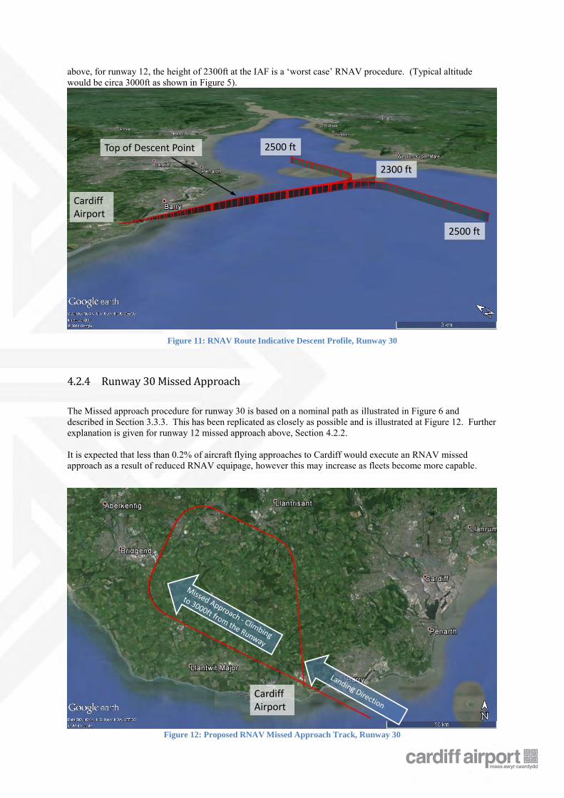
above, for runway 12, the height of 2300ft at the IAF is a ‘worst case’ RNAV procedure. (Typical altitude would be circa 3000ft as shown in Figure 5).
Figure 11: RNAV Route Indicative Descent Profile, Runway 30
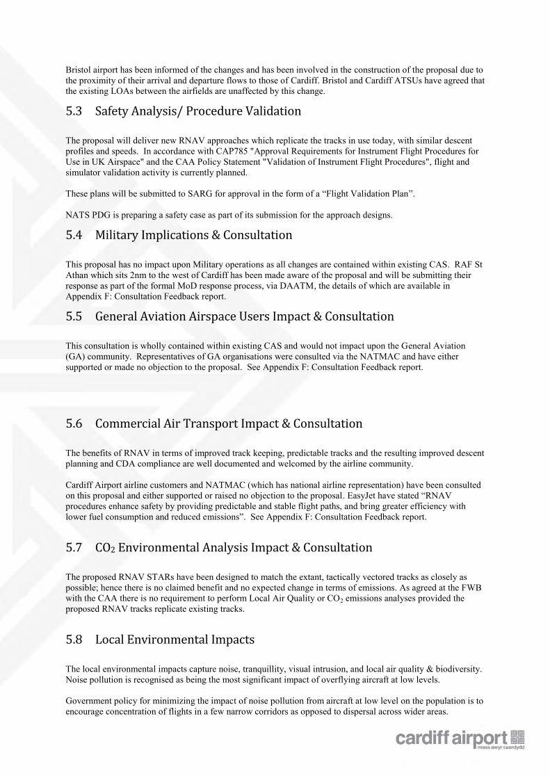
4.2.4 Runway 30 Missed Approach
The Missed approach procedure for runway 30 is based on a nominal path as illustrated in Figure 6 and described in Section 3.3.3. This has been replicated as closely as possible and is illustrated at Figure 12. Further explanation is given for runway 12 missed approach above, Section 4.2.2. It is expected that less than 0.2% of aircraft flying approaches to Cardiff would execute an RNAV missed approach as a result of reduced RNAV equipage, however this may increase as fleets become more capable.
Figure 12: Proposed RNAV Missed Approach Track, Runway 30
2300 ft
Cardiff Airport
Top of Descent Point
2500 ft
2500 ft
Cardiff Airport
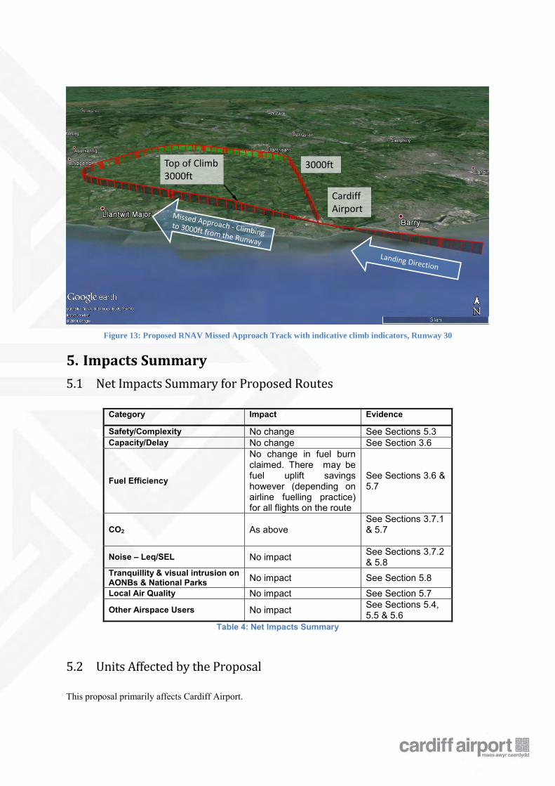
Figure 13: Proposed RNAV Missed Approach Track with indicative climb indicators, Runway 30
5. Impacts Summary
5.1 Net Impacts Summary for Proposed Routes
Category Impact Evidence
Safety/Complexity No change See Sections 5.3 Capacity/Delay No change See Section 3.6
Fuel Efficiency
No change in fuel burn claimed. There may be fuel uplift savings however (depending on airline fuelling practice) for all flights on the route
See Sections 3.6 & 5.7
CO2 As above See Sections 3.7.1 & 5.7
Noise – Leq/SEL No impact See Sections 3.7.2 & 5.8
Tranquillity & visual intrusion on AONBs & National Parks No impact See Section 5.8 Local Air Quality No impact See Section 5.7
Other Airspace Users No impact See Sections 5.4, 5.5 & 5.6
Table 4: Net Impacts Summary
5.2 Units Affected by the Proposal
This proposal primarily affects Cardiff Airport.
Cardiff Airport
Top of Climb3000ft
3000ft
Bristol airport has been informed of the changes and has been involved in the construction of the proposal due to the proximity of their arrival and departure flows to those of Cardiff. Bristol and Cardiff ATSUs have agreed that the existing LOAs between the airfields are unaffected by this change.
5.3 Safety Analysis/ Procedure Validation
The proposal will deliver new RNAV approaches which replicate the tracks in use today, with similar descent profiles and speeds. In accordance with CAP785 "Approval Requirements for Instrument Flight Procedures for Use in UK Airspace" and the CAA Policy Statement "Validation of Instrument Flight Procedures", flight and simulator validation activity is currently planned. These plans will be submitted to SARG for approval in the form of a “Flight Validation Plan”. NATS PDG is preparing a safety case as part of its submission for the approach designs.
5.4 Military Implications & Consultation
This proposal has no impact upon Military operations as all changes are contained within existing CAS. RAF St Athan which sits 2nm to the west of Cardiff has been made aware of the proposal and will be submitting their response as part of the formal MoD response process, via DAATM, the details of which are available in Appendix F: Consultation Feedback report.
5.5 General Aviation Airspace Users Impact & Consultation
This consultation is wholly contained within existing CAS and would not impact upon the General Aviation (GA) community. Representatives of GA organisations were consulted via the NATMAC and have either supported or made no objection to the proposal. See Appendix F: Consultation Feedback report.
5.6 Commercial Air Transport Impact & Consultation
The benefits of RNAV in terms of improved track keeping, predictable tracks and the resulting improved descent planning and CDA compliance are well documented and welcomed by the airline community. Cardiff Airport airline customers and NATMAC (which has national airline representation) have been consulted on this proposal and either supported or raised no objection to the proposal. EasyJet have stated “RNAV procedures enhance safety by providing predictable and stable flight paths, and bring greater efficiency with lower fuel consumption and reduced emissions”. See Appendix F: Consultation Feedback report.
5.7 CO2 Environmental Analysis Impact & Consultation
The proposed RNAV STARs have been designed to match the extant, tactically vectored tracks as closely as possible; hence there is no claimed benefit and no expected change in terms of emissions. As agreed at the FWB with the CAA there is no requirement to perform Local Air Quality or CO2 emissions analyses provided the proposed RNAV tracks replicate existing tracks.
5.8 Local Environmental Impacts
The local environmental impacts capture noise, tranquillity, visual intrusion, and local air quality & biodiversity. Noise pollution is recognised as being the most significant impact of overflying aircraft at low levels. Government policy for minimizing the impact of noise pollution from aircraft at low level on the population is to encourage concentration of flights in a few narrow corridors as opposed to dispersal across wider areas.
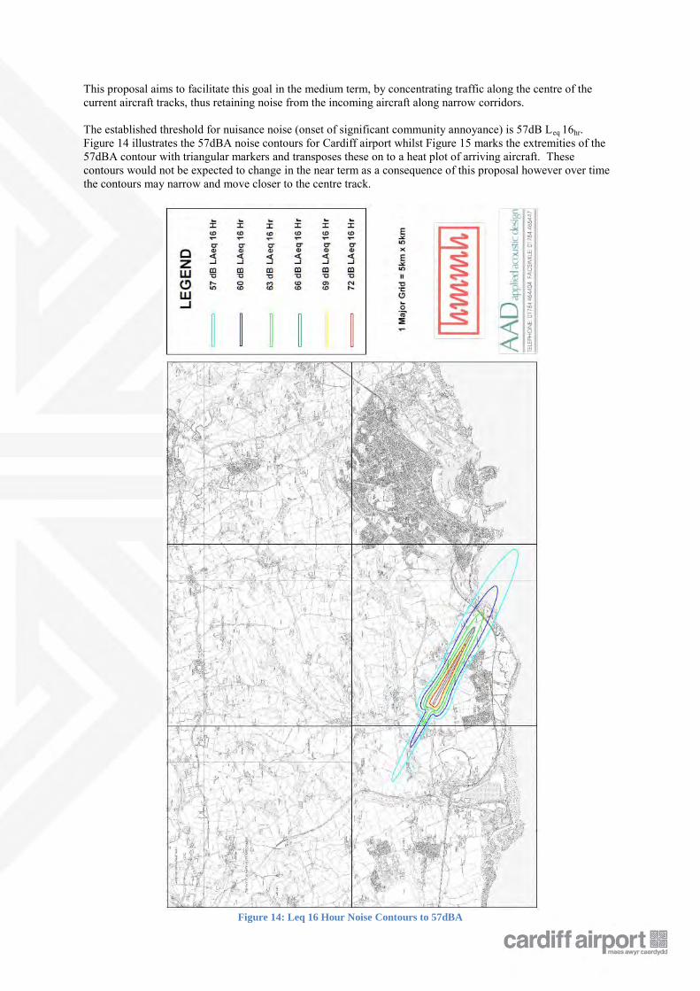
This proposal aims to facilitate this goal in the medium term, by concentrating traffic along the centre of the current aircraft tracks, thus retaining noise from the incoming aircraft along narrow corridors. The established threshold for nuisance noise (onset of significant community annoyance) is 57dB Leq 16hr. Figure 14 illustrates the 57dBA noise contours for Cardiff airport whilst Figure 15 marks the extremities of the 57dBA contour with triangular markers and transposes these on to a heat plot of arriving aircraft. These contours would not be expected to change in the near term as a consequence of this proposal however over time the contours may narrow and move closer to the centre track.
Figure 14: Leq 16 Hour Noise Contours to 57dBA
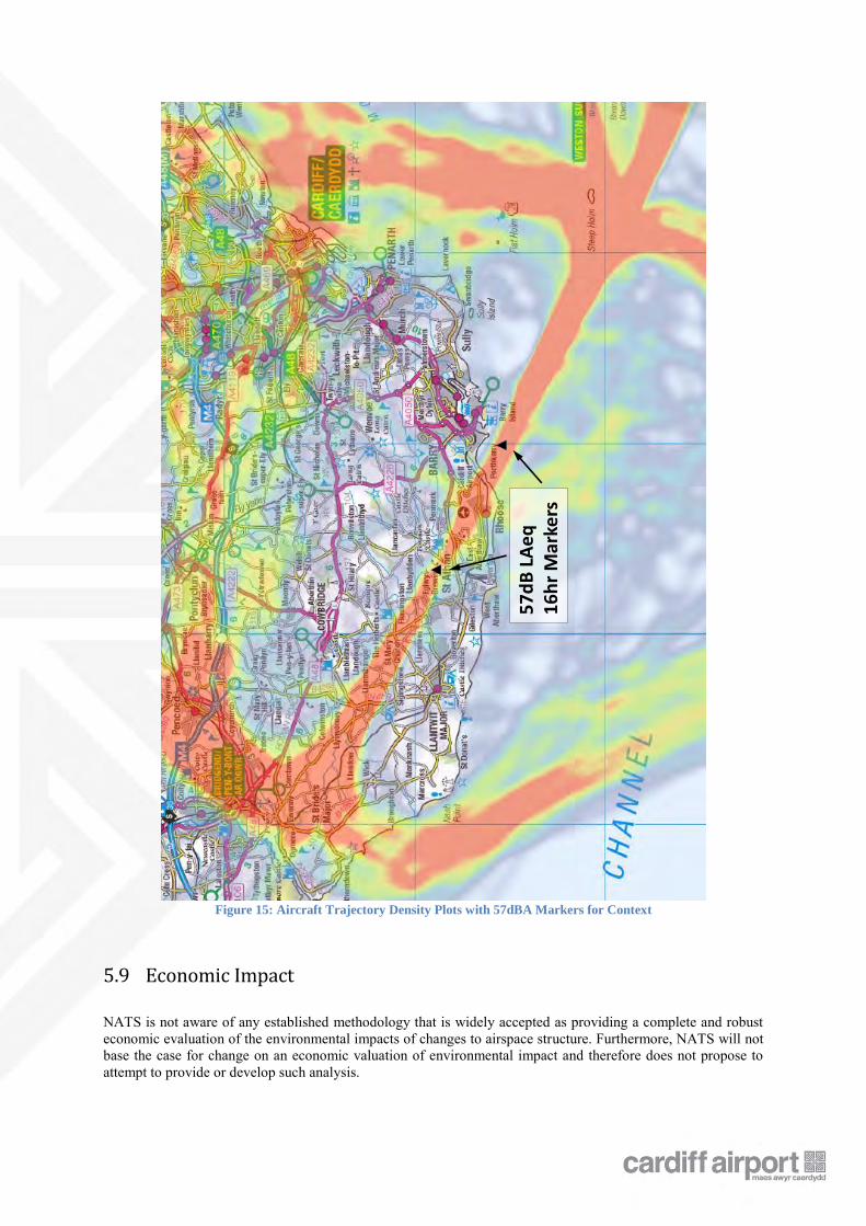
Figure 15: Aircraft Trajectory Density Plots with 57dBA Markers for Context
5.9 Economic Impact
NATS is not aware of any established methodology that is widely accepted as providing a complete and robust economic evaluation of the environmental impacts of changes to airspace structure. Furthermore, NATS will not base the case for change on an economic valuation of environmental impact and therefore does not propose to attempt to provide or develop such analysis.
57
dB
LA
eq
16
hr
Mar
kers
6. Consultation
6.1 Introduction
Between 16th December 2014 and 24th March 2015, Cardiff International Airport Limited carried out a consultation, seeking feedback from stakeholders on a proposal to replicate and implement the current aircraft approach tracks with more accurately defined routes utilising the capabilities of modern aircraft – namely Area Navigation (RNAV). A detailed consultation document was prepared which explained the RNAV proposals and how it would affect various stakeholders. The consultation document was posted on the Cardiff Airport website (click link to see the document) and an email was sent to the National Air Traffic Management Advisory Committee (NATMAC), directing them to the consultation document and inviting the members to respond. The consultation document was drafted using language to make it as accessible as possible to non-aviation consultees and was additionally made available in the welsh language. From this, one response was received from a member of the public along with 11 responses from organisations or individuals who had been explicitly invited to respond, resulting in a total of twelve responses. Prior to this, members of the Cardiff Airport Consultative Committee (ACC) were provided with an outline of the proposals at their meeting on 11th December 2014. It was made clear in the documentation that anybody could respond and that responses from members of the public were welcomed by CIAL. 12 responses were received and of those, two came from local authorities, one from the Military and three from the NATMAC List. Airlines were invited to respond via the NATMAC list and a total of four airlines took this opportunity. Each response, either group or individual organisation, has been included in the statistical measures. This gives the following results:
6 - Support 5 – No Objection 1 - Objection
A Feedback Report detailing the full list of consultees, their responses to the consultation and CIAL’s responses to their queries, was compiled and is included within this document as an embedded PDF document at Appendix F: Consultation Feedback report.
6.2 Issues arising from Objections
There were three separate issues raised in the objection received to this proposal. 1 – “The report highlights that RNAV is designed to keep aircraft "higher over ground for longer". However the proposal does not provide the descent heights approaching Runway 12, which may mean that aircraft are lower and noisier as they pass close to Llanblethian. New proposals should actually keep aircraft higher for longer during the descent and then descend to the airport closer to the runway to minimise noise to residents.” 2 – “This CAA and this proposal only considers noise affecting new residents, and makes no consideration to those residents already affected by noise from aircraft. This should be considered to improve the impact of the airport on residents.” 3 – “Also the current flight path of aircraft approaching Runway 12 shows aircraft coming from the north taking a short cut closer to Llanblethian. No change to this is mentioned.” The respondent also makes a generic statement that,
“In summary, the proposal lacks detail in specific areas regarding height of approaches, the affect on current residents and straying aircraft taking short cuts over residential areas.”
6.3 Responses to Issues arising from objections
1 – The consultation document shows current typical aircraft heights in bands for the approaches to Cardiff Airport for both runways (see consultation document Figures 3 & 5). Taking runway 12 as an example, the aircraft are anticipated to operate at similar heights as they do today however the consultation document illustrated the lowest level at which an aircraft operating an RNAV approach procedure is anticipated to be (see consultation document Figures 10 & 11). The consultation document indicated that the aircraft will be at 2400ft when joining the RNAV approach at the Initial Approach Fix and would stay at this height until reaching the Top of Descent point before descending to the threshold. The IAF and the TOD are clearly marked on the maps in the consultation document and represent a ‘worst case’ scenario.
The text within the document states that aircraft are more likely to maintain the heights which they operate at today as illustrated in the current typical height bands (Figures 3 & 5). What is not mentioned or illustrated however, as it is an exception case is that aircraft today have the option to descend to 1500ft in the area of the Final Approach Fix if they request to do so. Conversely, aircraft following RNAV procedures are not expected to do this.
The fact that current height bands and worst case scenario future heights were represented in the consultation document, gives Cardiff Airport confidence that objection to the proposal as stated does not justify a change to the proposal as presented. Aircraft aim to descend at a standard rate of 5.2% (3 degrees) as today and this proposal does not look to alter that.
2 – This proposal is written in the spirit of The governments overall policy on aviation noise, as established in the Aviation Policy Framework, which is to limit, and where possible, reduce, the number of people in the UK significantly affected by aircraft noise.
Consistent with this policy, the Government believes that in most circumstances, it is desirable to concentrate aircraft along the fewest possible number of specified routes in the vicinity of airports and that these routes should avoid densely populated areas as far as possible.
The proposed procedures have been designed to follow those areas where aircraft fly today, and using the RNAV technology ensure that a high degree of track keeping accuracy is maintained.
3 – This particular ‘short cut’ was not mentioned explicitly in the text of the consultation document. However, as the number of aircraft utilising RNAV approach procedures increase and follow the accurate track keeping proposed it is reasonable to expect the number of aircraft flying a ‘short cut’ route in the proximity to Llanblethian to decrease. This change will happen over time as more aircraft and crew are certified in the use of RNAV approaches.
7. Analysis of Options
Various options were considered throughout the design stage of the project. Option 7.2 Replications of Existing Track Concentrations, is the chosen option. All others listed below were considered but discounted.
7.1 Do Nothing
The option to “do nothing” and maintain the current operation would work in the short term but would not enable the improvement in aircraft operations (in terms of the benefits of increased safety, systemisation, resilience and CDAs) that RNAV approaches allow. Of the fleet of commercial passenger aircraft that use Cardiff airport many are either already equipped with the required cockpit technology or they plan to fit this technology and train their crews in the future, to enable the use of RNAV routes. Therefore, to enable a small benefit now and to enable a greater benefit in the future, the do nothing option has been discounted by Cardiff airport.
7.2 Replications of Existing Track Concentrations
To reduce the impact of the proposal and to avoid introducing aircraft noise to new areas local to the airport, replication of existing aircraft track concentrations are proposed. In this case the centreline of the track concentrations given in Figures 3 & 6 would be replicated for the approach, utilising the T-bar for the turns on to the final approach. This is the preferred option for Cardiff Airport and the option upon which the consultation material and
this proposal are based.
7.3 New Routes
The application of RNAV technology can be used to define accurately a route over the ground which avoids over-flight of populated areas but this would be more likely to increase the track mileage by having to route around population centres. However, in order to adhere as closely as possible to the principal of replication of existing routes, new routes are not being put forward in this proposal.
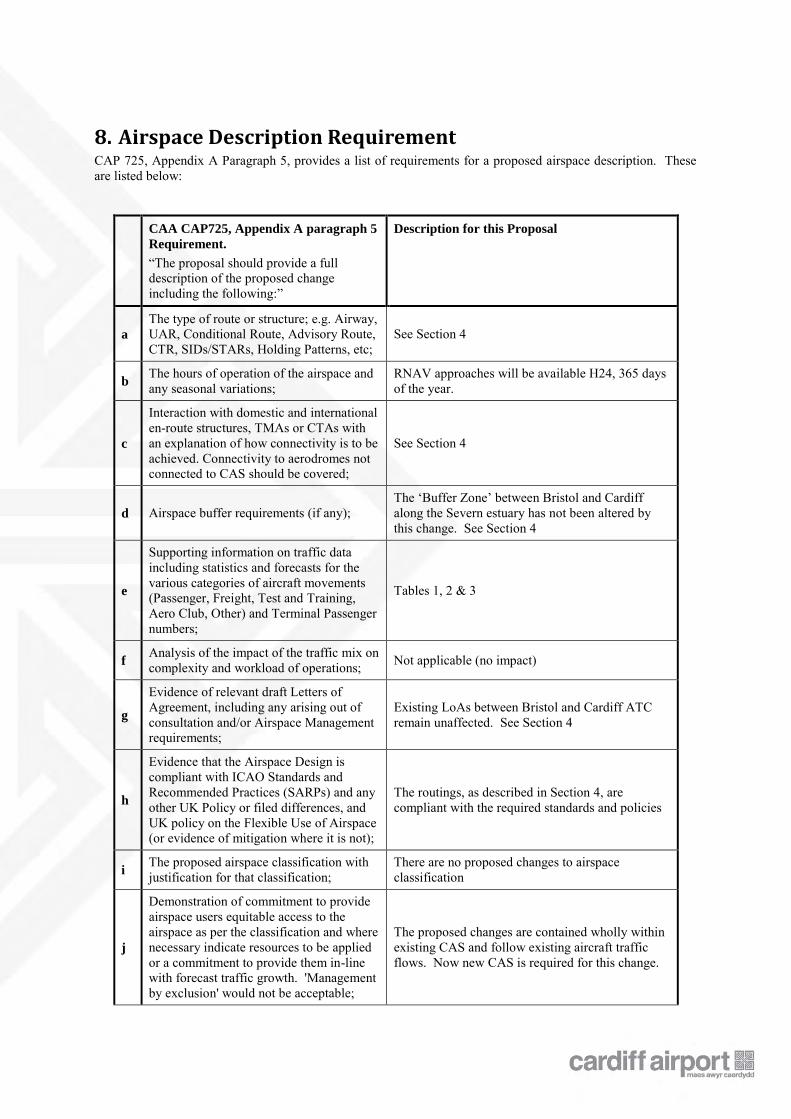
8. Airspace Description Requirement CAP 725, Appendix A Paragraph 5, provides a list of requirements for a proposed airspace description. These are listed below:
CAA CAP725, Appendix A paragraph 5
Requirement.
“The proposal should provide a full description of the proposed change including the following:”
Description for this Proposal
a
The type of route or structure; e.g. Airway, UAR, Conditional Route, Advisory Route, CTR, SIDs/STARs, Holding Patterns, etc;
See Section 4
b The hours of operation of the airspace and any seasonal variations;
RNAV approaches will be available H24, 365 days of the year.
c
Interaction with domestic and international en-route structures, TMAs or CTAs with an explanation of how connectivity is to be achieved. Connectivity to aerodromes not connected to CAS should be covered;
See Section 4
d Airspace buffer requirements (if any); The ‘Buffer Zone’ between Bristol and Cardiff along the Severn estuary has not been altered by this change. See Section 4
e
Supporting information on traffic data including statistics and forecasts for the various categories of aircraft movements (Passenger, Freight, Test and Training, Aero Club, Other) and Terminal Passenger numbers;
Tables 1, 2 & 3
f Analysis of the impact of the traffic mix on complexity and workload of operations; Not applicable (no impact)
g
Evidence of relevant draft Letters of Agreement, including any arising out of consultation and/or Airspace Management requirements;
Existing LoAs between Bristol and Cardiff ATC remain unaffected. See Section 4
h
Evidence that the Airspace Design is compliant with ICAO Standards and Recommended Practices (SARPs) and any other UK Policy or filed differences, and UK policy on the Flexible Use of Airspace (or evidence of mitigation where it is not);
The routings, as described in Section 4, are compliant with the required standards and policies
i The proposed airspace classification with justification for that classification;
There are no proposed changes to airspace classification
j
Demonstration of commitment to provide airspace users equitable access to the airspace as per the classification and where necessary indicate resources to be applied or a commitment to provide them in-line with forecast traffic growth. 'Management by exclusion' would not be acceptable;
The proposed changes are contained wholly within existing CAS and follow existing aircraft traffic flows. Now new CAS is required for this change.

k Details of and justification for any delegation of ATS. No proposed changes to delegation of ATS
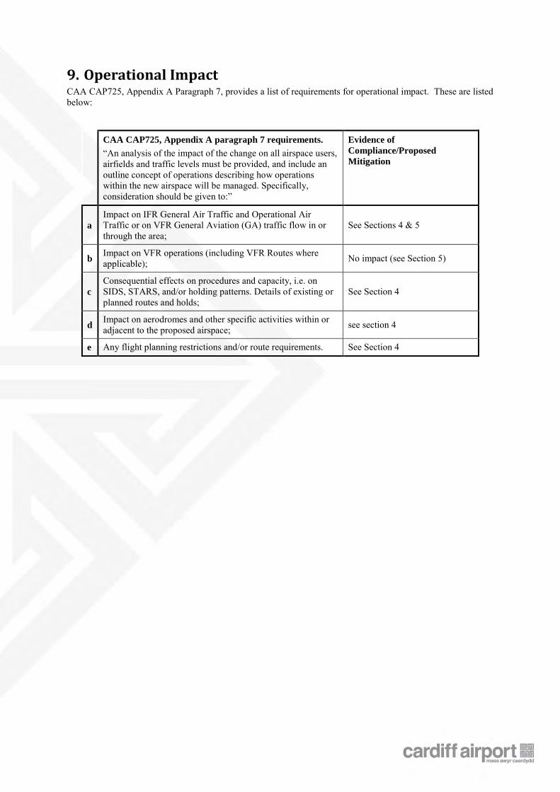
9. Operational Impact CAA CAP725, Appendix A Paragraph 7, provides a list of requirements for operational impact. These are listed below:
CAA CAP725, Appendix A paragraph 7 requirements.
“An analysis of the impact of the change on all airspace users, airfields and traffic levels must be provided, and include an outline concept of operations describing how operations within the new airspace will be managed. Specifically, consideration should be given to:”
Evidence of
Compliance/Proposed
Mitigation
a
Impact on IFR General Air Traffic and Operational Air Traffic or on VFR General Aviation (GA) traffic flow in or through the area;
See Sections 4 & 5
b Impact on VFR operations (including VFR Routes where applicable); No impact (see Section 5)
c
Consequential effects on procedures and capacity, i.e. on SIDS, STARS, and/or holding patterns. Details of existing or planned routes and holds;
See Section 4
d Impact on aerodromes and other specific activities within or adjacent to the proposed airspace; see section 4
e Any flight planning restrictions and/or route requirements. See Section 4
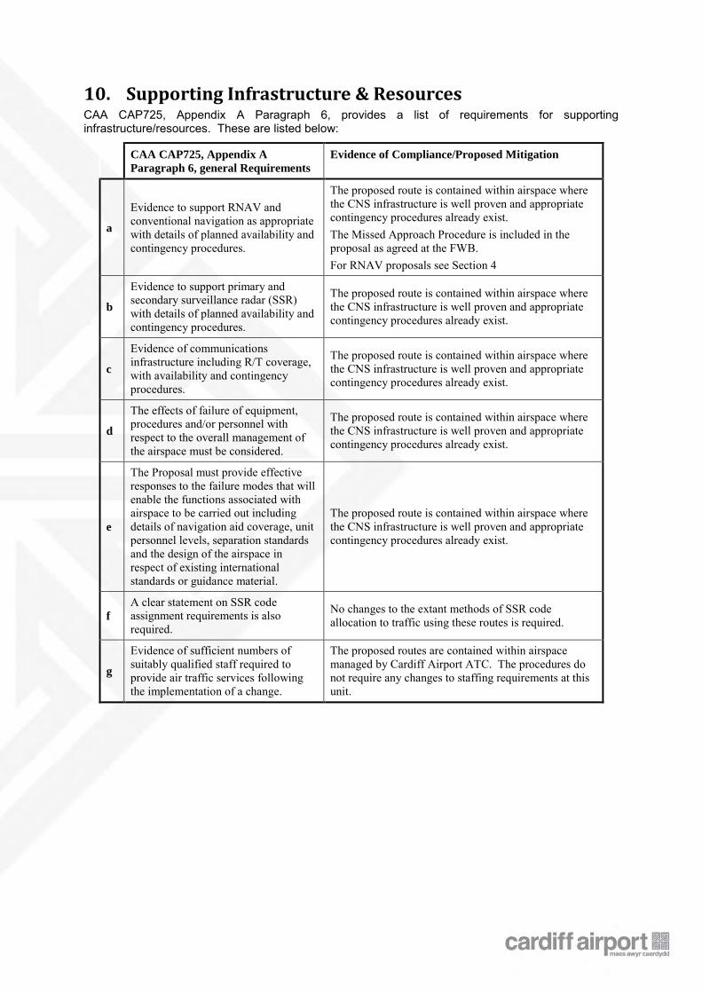
10. Supporting Infrastructure & Resources CAA CAP725, Appendix A Paragraph 6, provides a list of requirements for supporting infrastructure/resources. These are listed below:
CAA CAP725, Appendix A
Paragraph 6, general Requirements
Evidence of Compliance/Proposed Mitigation
a
Evidence to support RNAV and conventional navigation as appropriate with details of planned availability and contingency procedures.
The proposed route is contained within airspace where the CNS infrastructure is well proven and appropriate contingency procedures already exist. The Missed Approach Procedure is included in the proposal as agreed at the FWB. For RNAV proposals see Section 4
b
Evidence to support primary and secondary surveillance radar (SSR) with details of planned availability and contingency procedures.
The proposed route is contained within airspace where the CNS infrastructure is well proven and appropriate contingency procedures already exist.
c
Evidence of communications infrastructure including R/T coverage, with availability and contingency procedures.
The proposed route is contained within airspace where the CNS infrastructure is well proven and appropriate contingency procedures already exist.
d
The effects of failure of equipment, procedures and/or personnel with respect to the overall management of the airspace must be considered.
The proposed route is contained within airspace where the CNS infrastructure is well proven and appropriate contingency procedures already exist.
e
The Proposal must provide effective responses to the failure modes that will enable the functions associated with airspace to be carried out including details of navigation aid coverage, unit personnel levels, separation standards and the design of the airspace in respect of existing international standards or guidance material.
The proposed route is contained within airspace where the CNS infrastructure is well proven and appropriate contingency procedures already exist.
f
A clear statement on SSR code assignment requirements is also required.
No changes to the extant methods of SSR code allocation to traffic using these routes is required.
g
Evidence of sufficient numbers of suitably qualified staff required to provide air traffic services following the implementation of a change.
The proposed routes are contained within airspace managed by Cardiff Airport ATC. The procedures do not require any changes to staffing requirements at this unit.
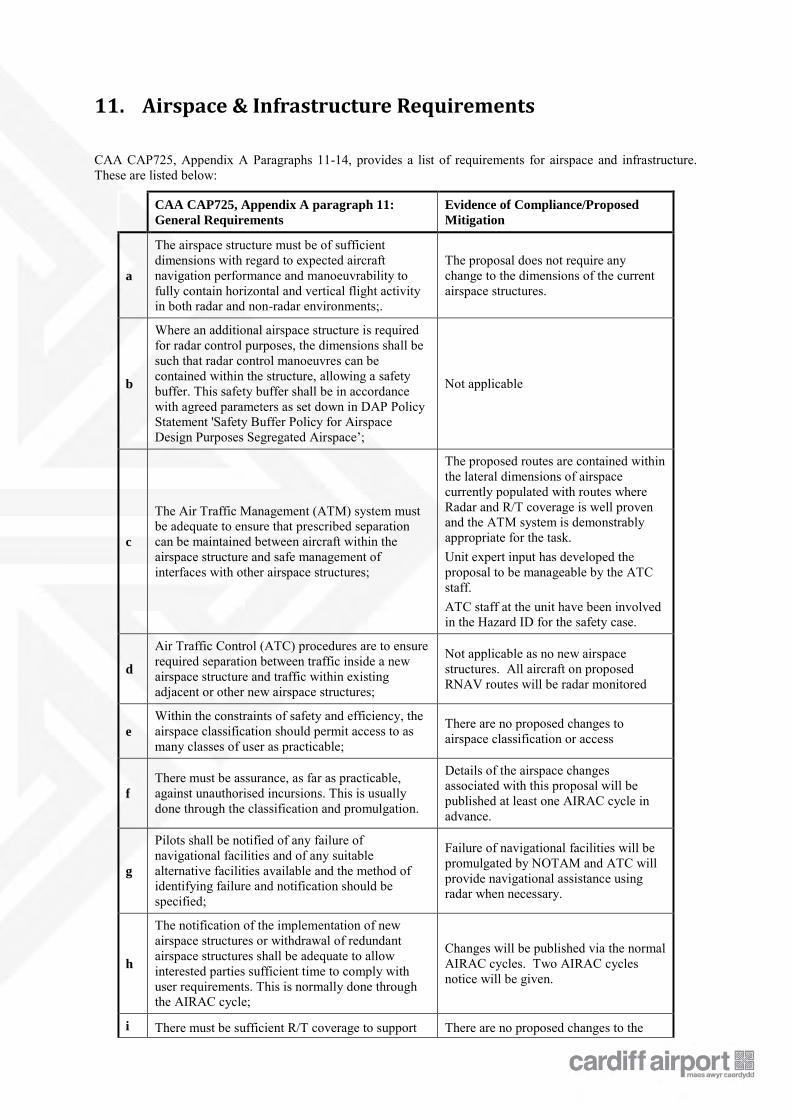
11. Airspace & Infrastructure Requirements CAA CAP725, Appendix A Paragraphs 11-14, provides a list of requirements for airspace and infrastructure. These are listed below:
CAA CAP725, Appendix A paragraph 11:
General Requirements
Evidence of Compliance/Proposed
Mitigation
a
The airspace structure must be of sufficient dimensions with regard to expected aircraft navigation performance and manoeuvrability to fully contain horizontal and vertical flight activity in both radar and non-radar environments;.
The proposal does not require any change to the dimensions of the current airspace structures.
b
Where an additional airspace structure is required for radar control purposes, the dimensions shall be such that radar control manoeuvres can be contained within the structure, allowing a safety buffer. This safety buffer shall be in accordance with agreed parameters as set down in DAP Policy Statement 'Safety Buffer Policy for Airspace Design Purposes Segregated Airspace’;
Not applicable
c
The Air Traffic Management (ATM) system must be adequate to ensure that prescribed separation can be maintained between aircraft within the airspace structure and safe management of interfaces with other airspace structures;
The proposed routes are contained within the lateral dimensions of airspace currently populated with routes where Radar and R/T coverage is well proven and the ATM system is demonstrably appropriate for the task. Unit expert input has developed the proposal to be manageable by the ATC staff. ATC staff at the unit have been involved in the Hazard ID for the safety case.
d
Air Traffic Control (ATC) procedures are to ensure required separation between traffic inside a new airspace structure and traffic within existing adjacent or other new airspace structures;
Not applicable as no new airspace structures. All aircraft on proposed RNAV routes will be radar monitored
e
Within the constraints of safety and efficiency, the airspace classification should permit access to as many classes of user as practicable;
There are no proposed changes to airspace classification or access
f
There must be assurance, as far as practicable, against unauthorised incursions. This is usually done through the classification and promulgation.
Details of the airspace changes associated with this proposal will be published at least one AIRAC cycle in advance.
g
Pilots shall be notified of any failure of navigational facilities and of any suitable alternative facilities available and the method of identifying failure and notification should be specified;
Failure of navigational facilities will be promulgated by NOTAM and ATC will provide navigational assistance using radar when necessary.
h
The notification of the implementation of new airspace structures or withdrawal of redundant airspace structures shall be adequate to allow interested parties sufficient time to comply with user requirements. This is normally done through the AIRAC cycle;
Changes will be published via the normal AIRAC cycles. Two AIRAC cycles notice will be given.
i There must be sufficient R/T coverage to support There are no proposed changes to the
the ATM system within the totality of proposed controlled airspace.
dimensions of CAS and aircraft already fly the proposed routes. R/T coverage is demonstrably adequate for the task.
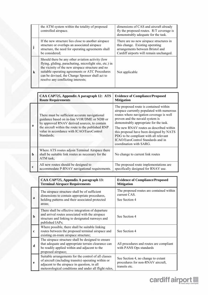
j
If the new structure lies close to another airspace structure or overlaps an associated airspace structure, the need for operating agreements shall be considered;
There are no new airspace structures in this change. Existing operating arrangements between Bristol and Cardiff airports will remain unchanged.
k
Should there be any other aviation activity (low flying, gliding, parachuting, microlight site, etc.) in the vicinity of the new airspace structure and no suitable operating agreements or ATC Procedures can be devised, the Change Sponsor shall act to resolve any conflicting interests;
Not applicable
CAA CAP725, Appendix A paragraph 12: ATS
Route Requirements
Evidence of Compliance/Proposed
Mitigation
a
There must be sufficient accurate navigational guidance based on in-line VOR/DME or NDB or by approved RNAV derived sources, to contain the aircraft within the route to the published RNP value in accordance with ICAO/EuroControl Standards;
The proposed route is contained within airspace currently populated with numerous routes where navigation coverage is well proven and the navaid system is demonstrably appropriate for the task. The new RNAV routes as described within this proposal have been designed by NATS PDG to be compliant with all relevant ICAO/EuroControl Standards and in coordination with SARG.
b
Where ATS routes adjoin Terminal Airspace there shall be suitable link routes as necessary for the ATM task;
No change to current link routes
c All new routes should be designed to accommodate P-RNAV navigational requirements.
The proposed route implementations are specifically designed for RNAV use.
CAA CAP725, Appendix A paragraph 13:
Terminal Airspace Requirements
Evidence of Compliance/Proposed
Mitigation
a
The airspace structure shall be of sufficient dimensions to contain appropriate procedures, holding patterns and their associated protected areas;
The proposed routes are contained within current CAS. See Section 4
b
There shall be effective integration of departure and arrival routes associated with the airspace structure and linking to designated runways and published IAPs;
See Section 4
c
Where possible, there shall be suitable linking routes between the proposed terminal airspace and existing en-route airspace structure;
See Section 4
d
The airspace structure shall be designed to ensure that adequate and appropriate terrain clearance can be readily applied within and adjacent to the proposed airspace;
All procedures and routes are compliant with PANS Ops standards
e
Suitable arrangements for the control of all classes of aircraft (including transits) operating within or adjacent to the airspace in question, in all meteorological conditions and under all flight rules,
See Section 4, no change to extant procedures for non-RNAV aircraft, transits etc.
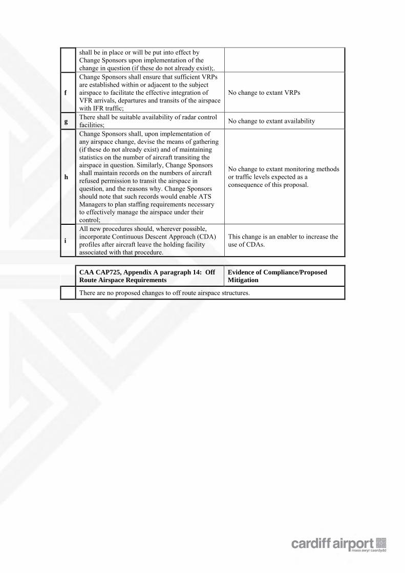
shall be in place or will be put into effect by Change Sponsors upon implementation of the change in question (if these do not already exist);.
f
Change Sponsors shall ensure that sufficient VRPs are established within or adjacent to the subject airspace to facilitate the effective integration of VFR arrivals, departures and transits of the airspace with IFR traffic;
No change to extant VRPs
g There shall be suitable availability of radar control facilities; No change to extant availability
h
Change Sponsors shall, upon implementation of any airspace change, devise the means of gathering (if these do not already exist) and of maintaining statistics on the number of aircraft transiting the airspace in question. Similarly, Change Sponsors shall maintain records on the numbers of aircraft refused permission to transit the airspace in question, and the reasons why. Change Sponsors should note that such records would enable ATS Managers to plan staffing requirements necessary to effectively manage the airspace under their control;
No change to extant monitoring methods or traffic levels expected as a consequence of this proposal.
i
All new procedures should, wherever possible, incorporate Continuous Descent Approach (CDA) profiles after aircraft leave the holding facility associated with that procedure.
This change is an enabler to increase the use of CDAs.
CAA CAP725, Appendix A paragraph 14: Off
Route Airspace Requirements
Evidence of Compliance/Proposed
Mitigation
There are no proposed changes to off route airspace structures.
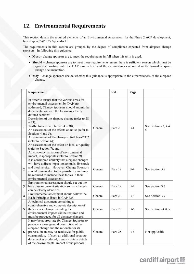
12. Environmental Requirements
This section details the required elements of an Environmental Assessment for the Phase 2 ACP development, based upon CAP 725 Appendix B.
The requirements in this section are grouped by the degree of compliance expected from airspace change sponsors. In following this guidance:
Must – change sponsors are to meet the requirements in full when this term is used.
Should – change sponsors are to meet these requirements unless there is sufficient reason which must be agreed in writing with the DAP case officer and the circumstances recorded in the formal airspace change documentation.
May – change sponsors decide whether this guidance is appropriate to the circumstances of the airspace change.
Requirement Ref. Page
1
In order to ensure that the various areas for environmental assessment by DAP are addressed, Change Sponsors should submit the documentation with the following clearly defined sections: Description of the airspace change (refer to 28 – 33); Traffic forecasts (refer to 34 – 38); An assessment of the effects on noise (refer to Sections 4 and 5); An assessment of the change in fuel burn/CO2 (refer to Section 6); An assessment of the effect on local air quality (refer to Section 7); and An economic valuation of environmental impact, if appropriate (refer to Section 9).
General Para 2 B-1 See Sections 3, 4 & 5
2
It is considered unlikely that airspace changes will have a direct impact on animals, livestock and biodiversity. However, Change Sponsors should remain alert to the possibility and may be required to include these topics in their environmental assessment.
General Para 18 B-4 See Section 5.8
3
Environmental assessment should set out the base case or current situation so that changes can be clearly identified.
General Para 19 B-4 See Section 3.7
4 Environmental assessment should follow the Basic Principles listed in CAP 725. General Para 20 B-4 See Section 3.7
5
A technical document containing a comprehensive and complete description of the airspace change including the environmental impact will be required and must be produced for all airspace changes.
General Para 25 B-6 See Sections 4 & 5
6
It may be appropriate for Change Sponsors to produce a more general description of the airspace change and the rationale for its proposal in an easy-to-read style for public consumption. If such an additional separate document is produced, it must contain details of the environmental impact of the proposal.
General Para 25 B-6 Not applicable
Requirement Ref. Page
7
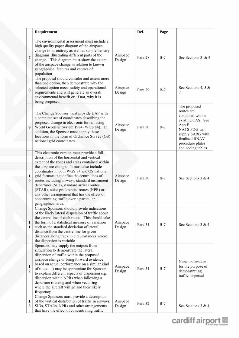
The environmental assessment must include a high quality paper diagram of the airspace change in its entirety as well as supplementary diagrams Illustrating different parts of the change. This diagram must show the extent of the airspace change in relation to known geographical features and centres of population
Airspace Design Para 28 B-7 See Sections 3 & 4
8
The proposal should consider and assess more than one option, then demonstrate why the selected option meets safety and operational requirements and will generate an overall environmental benefit or, if not, why it is being proposed.
Airspace Design Para 29 B-7 See Sections 4, 5 &
7
9
The Change Sponsor must provide DAP with a complete set of coordinates describing the proposed change in electronic format using World Geodetic System 1984 (WGS 84). In addition, the Sponsor must supply these locations in the form of Ordnance Survey (OS) national grid coordinates.
Airspace Design Para 30 B-7
The proposed routes are contained within existing CAS. See App E. NATS PDG will supply SARG with finalised RNAV procedure plates and coding tables
1
0
This electronic version must provide a full description of the horizontal and vertical extent of the zones and areas contained within the airspace change. It must also include coordinates in both WGS 84 and OS national grid formats that define the centre lines of routes including airways, standard instrument departures (SID), standard arrival routes (STAR), noise preferential routes (NPR) or any other arrangement that has the effect of concentrating traffic over a particular geographical area.
Airspace Design Para 30 B-7 See Sections 3 & 4
1
1
Change Sponsors should provide indications of the likely lateral dispersion of traffic about the centre line of each route. This should take the form of a statistical measure of variation such as the standard deviation of lateral distance from the centre line for given distances along track in circumstances where the dispersion is variable.
Airspace Design Para 31 B-7 See Sections 3 & 4
1
2
Sponsors may supply the outputs from simulation to demonstrate the lateral dispersion of traffic within the proposed airspace change or bring forward evidence based on actual performance on a similar kind of route. It may be appropriate for Sponsors to explain different aspects of dispersion e.g. dispersion within NPRs when following a departure routeing and when vectoring – where the aircraft will go and their likely frequency
Airspace Design Para 31 B-7
None undertaken for the purpose of demonstrating traffic dispersal
1
3
Change Sponsors must provide a description of the vertical distribution of traffic in airways, SIDs, STARs, NPRs and other arrangements that have the effect of concentrating traffic
Airspace Design Para 32 B-7
See Sections 3 & 4
Requirement Ref. Page
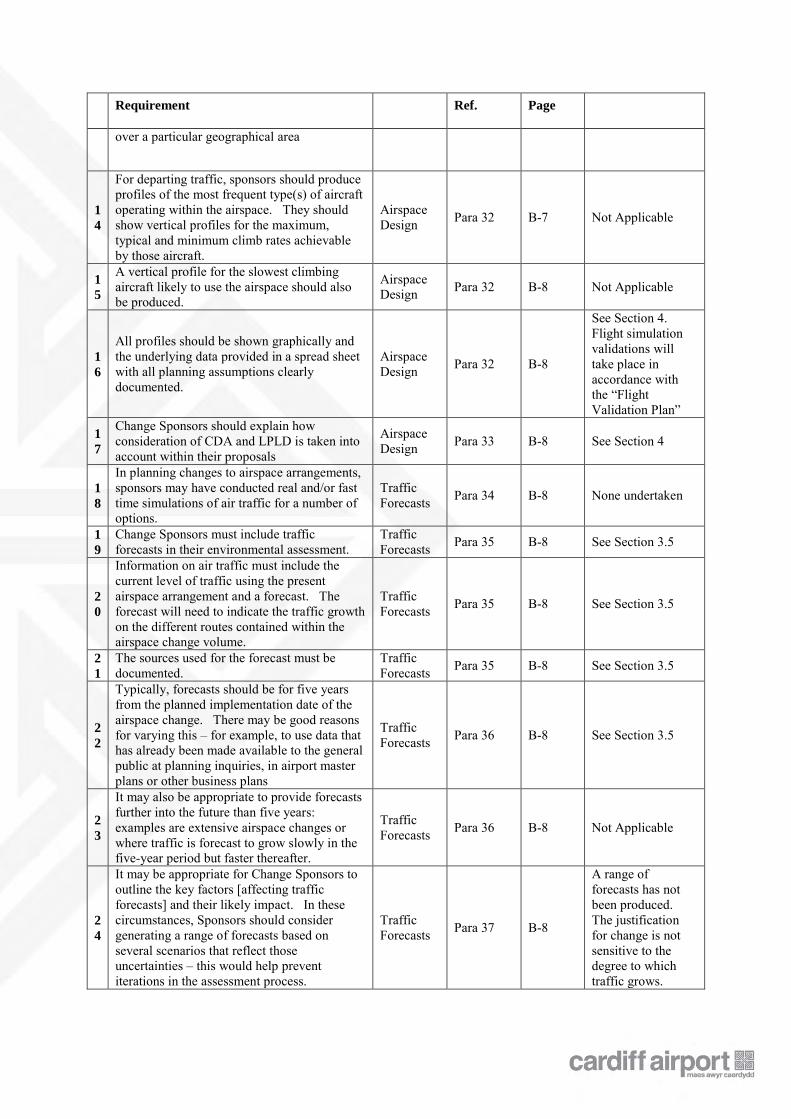
over a particular geographical area
1
4
For departing traffic, sponsors should produce profiles of the most frequent type(s) of aircraft operating within the airspace. They should show vertical profiles for the maximum, typical and minimum climb rates achievable by those aircraft.
Airspace Design Para 32 B-7 Not Applicable
1
5
A vertical profile for the slowest climbing aircraft likely to use the airspace should also be produced.
Airspace Design Para 32 B-8 Not Applicable
1
6
All profiles should be shown graphically and the underlying data provided in a spread sheet with all planning assumptions clearly documented.
Airspace Design Para 32 B-8
See Section 4. Flight simulation validations will take place in accordance with the “Flight Validation Plan”
1
7
Change Sponsors should explain how consideration of CDA and LPLD is taken into account within their proposals
Airspace Design Para 33 B-8
See Section 4
1
8
In planning changes to airspace arrangements, sponsors may have conducted real and/or fast time simulations of air traffic for a number of options.
Traffic Forecasts Para 34 B-8 None undertaken
1
9
Change Sponsors must include traffic forecasts in their environmental assessment.
Traffic Forecasts Para 35 B-8 See Section 3.5
2
0
Information on air traffic must include the current level of traffic using the present airspace arrangement and a forecast. The forecast will need to indicate the traffic growth on the different routes contained within the airspace change volume.
Traffic Forecasts Para 35 B-8 See Section 3.5
2
1
The sources used for the forecast must be documented.
Traffic Forecasts Para 35 B-8 See Section 3.5
2
2
Typically, forecasts should be for five years from the planned implementation date of the airspace change. There may be good reasons for varying this – for example, to use data that has already been made available to the general public at planning inquiries, in airport master plans or other business plans
Traffic Forecasts Para 36 B-8 See Section 3.5
2
3
It may also be appropriate to provide forecasts further into the future than five years: examples are extensive airspace changes or where traffic is forecast to grow slowly in the five-year period but faster thereafter.
Traffic Forecasts Para 36 B-8 Not Applicable
2
4
It may be appropriate for Change Sponsors to outline the key factors [affecting traffic forecasts] and their likely impact. In these circumstances, Sponsors should consider generating a range of forecasts based on several scenarios that reflect those uncertainties – this would help prevent iterations in the assessment process.
Traffic Forecasts Para 37 B-8
A range of forecasts has not been produced. The justification for change is not sensitive to the degree to which traffic grows.
Requirement Ref. Page
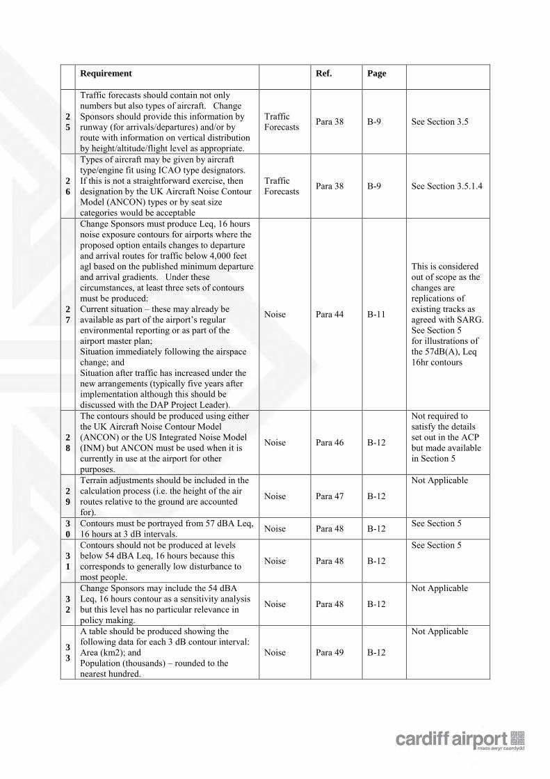
2
5
Traffic forecasts should contain not only numbers but also types of aircraft. Change Sponsors should provide this information by runway (for arrivals/departures) and/or by route with information on vertical distribution by height/altitude/flight level as appropriate.
Traffic Forecasts Para 38 B-9 See Section 3.5
2
6
Types of aircraft may be given by aircraft type/engine fit using ICAO type designators. If this is not a straightforward exercise, then designation by the UK Aircraft Noise Contour Model (ANCON) types or by seat size categories would be acceptable
Traffic Forecasts Para 38 B-9 See Section 3.5.1.4
2
7
Change Sponsors must produce Leq, 16 hours noise exposure contours for airports where the proposed option entails changes to departure and arrival routes for traffic below 4,000 feet agl based on the published minimum departure and arrival gradients. Under these circumstances, at least three sets of contours must be produced: Current situation – these may already be available as part of the airport’s regular environmental reporting or as part of the airport master plan; Situation immediately following the airspace change; and Situation after traffic has increased under the new arrangements (typically five years after implementation although this should be discussed with the DAP Project Leader).
Noise Para 44 B-11
This is considered out of scope as the changes are replications of existing tracks as agreed with SARG. See Section 5 for illustrations of the 57dB(A), Leq 16hr contours
2
8
The contours should be produced using either the UK Aircraft Noise Contour Model (ANCON) or the US Integrated Noise Model (INM) but ANCON must be used when it is currently in use at the airport for other purposes.
Noise Para 46 B-12
Not required to satisfy the details set out in the ACP but made available in Section 5
2
9
Terrain adjustments should be included in the calculation process (i.e. the height of the air routes relative to the ground are accounted for).
Noise Para 47 B-12
Not Applicable
3
0
Contours must be portrayed from 57 dBA Leq, 16 hours at 3 dB intervals. Noise Para 48 B-12 See Section 5
3
1
Contours should not be produced at levels below 54 dBA Leq, 16 hours because this corresponds to generally low disturbance to most people.
Noise Para 48 B-12
See Section 5
3
2
Change Sponsors may include the 54 dBA Leq, 16 hours contour as a sensitivity analysis but this level has no particular relevance in policy making.
Noise Para 48 B-12
Not Applicable
3
3
A table should be produced showing the following data for each 3 dB contour interval: Area (km2); and Population (thousands) – rounded to the nearest hundred.
Noise Para 49 B-12
Not Applicable
Requirement Ref. Page
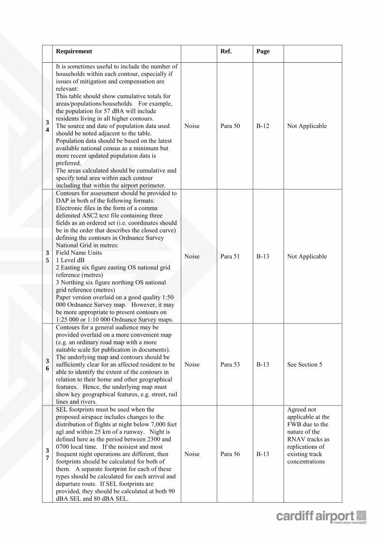
3
4
It is sometimes useful to include the number of households within each contour, especially if issues of mitigation and compensation are relevant: This table should show cumulative totals for areas/populations/households. For example, the population for 57 dBA will include residents living in all higher contours. The source and date of population data used should be noted adjacent to the table. Population data should be based on the latest available national census as a minimum but more recent updated population data is preferred. The areas calculated should be cumulative and specify total area within each contour including that within the airport perimeter.
Noise Para 50 B-12 Not Applicable
3
5
Contours for assessment should be provided to DAP in both of the following formats: Electronic files in the form of a comma delimited ASC2 text file containing three fields as an ordered set (i.e. coordinates should be in the order that describes the closed curve) defining the contours in Ordnance Survey National Grid in metres: Field Name Units 1 Level dB 2 Easting six figure easting OS national grid reference (metres) 3 Northing six figure northing OS national grid reference (metres) Paper version overlaid on a good quality 1:50 000 Ordnance Survey map. However, it may be more appropriate to present contours on 1:25 000 or 1:10 000 Ordnance Survey maps.
Noise Para 51 B-13 Not Applicable
3
6
Contours for a general audience may be provided overlaid on a more convenient map (e.g. an ordinary road map with a more suitable scale for publication in documents). The underlying map and contours should be sufficiently clear for an affected resident to be able to identify the extent of the contours in relation to their home and other geographical features. Hence, the underlying map must show key geographical features, e.g. street, rail lines and rivers.
Noise Para 53 B-13 See Section 5
3
7
SEL footprints must be used when the proposed airspace includes changes to the distribution of flights at night below 7,000 feet agl and within 25 km of a runway. Night is defined here as the period between 2300 and 0700 local time. If the noisiest and most frequent night operations are different, then footprints should be calculated for both of them. A separate footprint for each of these types should be calculated for each arrival and departure route. If SEL footprints are provided, they should be calculated at both 90 dBA SEL and 80 dBA SEL.
Noise Para 56 B-13
Agreed not applicable at the FWB due to the nature of the RNAV tracks as replications of existing track concentrations
Requirement Ref. Page
3
8
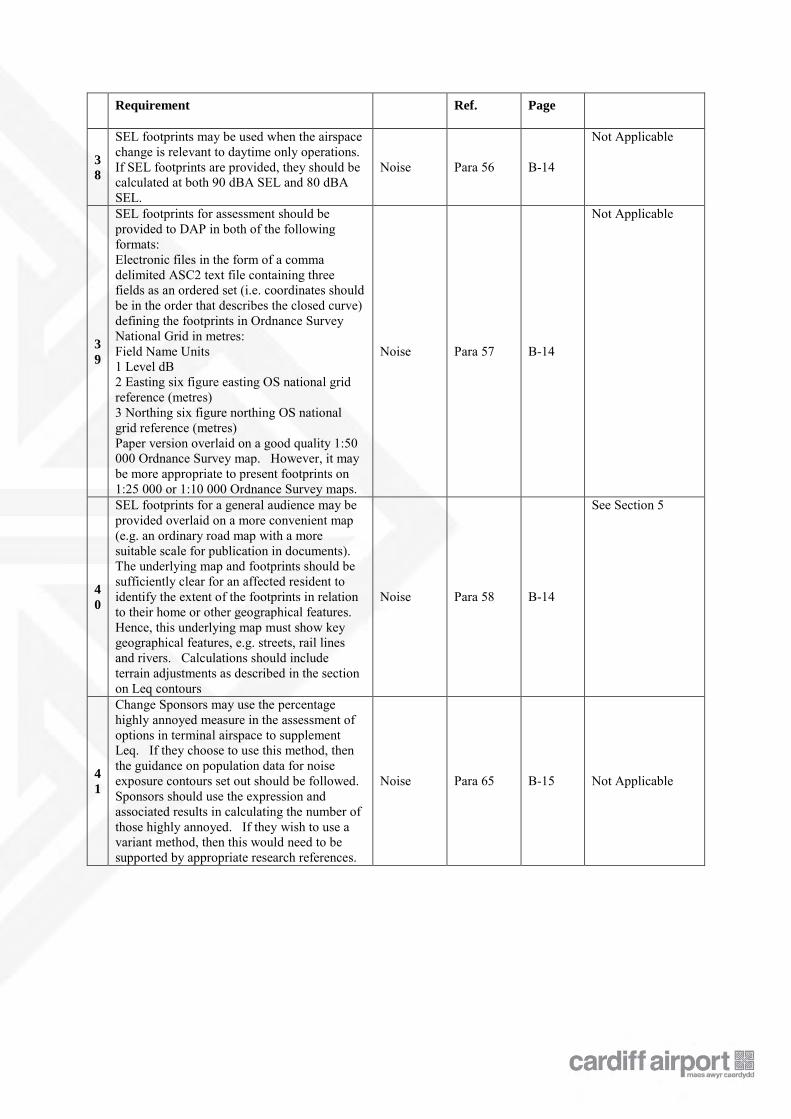
SEL footprints may be used when the airspace change is relevant to daytime only operations. If SEL footprints are provided, they should be calculated at both 90 dBA SEL and 80 dBA SEL.
Noise Para 56 B-14
Not Applicable
3
9
SEL footprints for assessment should be provided to DAP in both of the following formats: Electronic files in the form of a comma delimited ASC2 text file containing three fields as an ordered set (i.e. coordinates should be in the order that describes the closed curve) defining the footprints in Ordnance Survey National Grid in metres: Field Name Units 1 Level dB 2 Easting six figure easting OS national grid reference (metres) 3 Northing six figure northing OS national grid reference (metres) Paper version overlaid on a good quality 1:50 000 Ordnance Survey map. However, it may be more appropriate to present footprints on 1:25 000 or 1:10 000 Ordnance Survey maps.
Noise Para 57 B-14
Not Applicable
4
0
SEL footprints for a general audience may be provided overlaid on a more convenient map (e.g. an ordinary road map with a more suitable scale for publication in documents). The underlying map and footprints should be sufficiently clear for an affected resident to identify the extent of the footprints in relation to their home or other geographical features. Hence, this underlying map must show key geographical features, e.g. streets, rail lines and rivers. Calculations should include terrain adjustments as described in the section on Leq contours
Noise Para 58 B-14
See Section 5
4
1
Change Sponsors may use the percentage highly annoyed measure in the assessment of options in terminal airspace to supplement Leq. If they choose to use this method, then the guidance on population data for noise exposure contours set out should be followed. Sponsors should use the expression and associated results in calculating the number of those highly annoyed. If they wish to use a variant method, then this would need to be supported by appropriate research references.
Noise Para 65 B-15 Not Applicable
Requirement Ref. Page
4
2
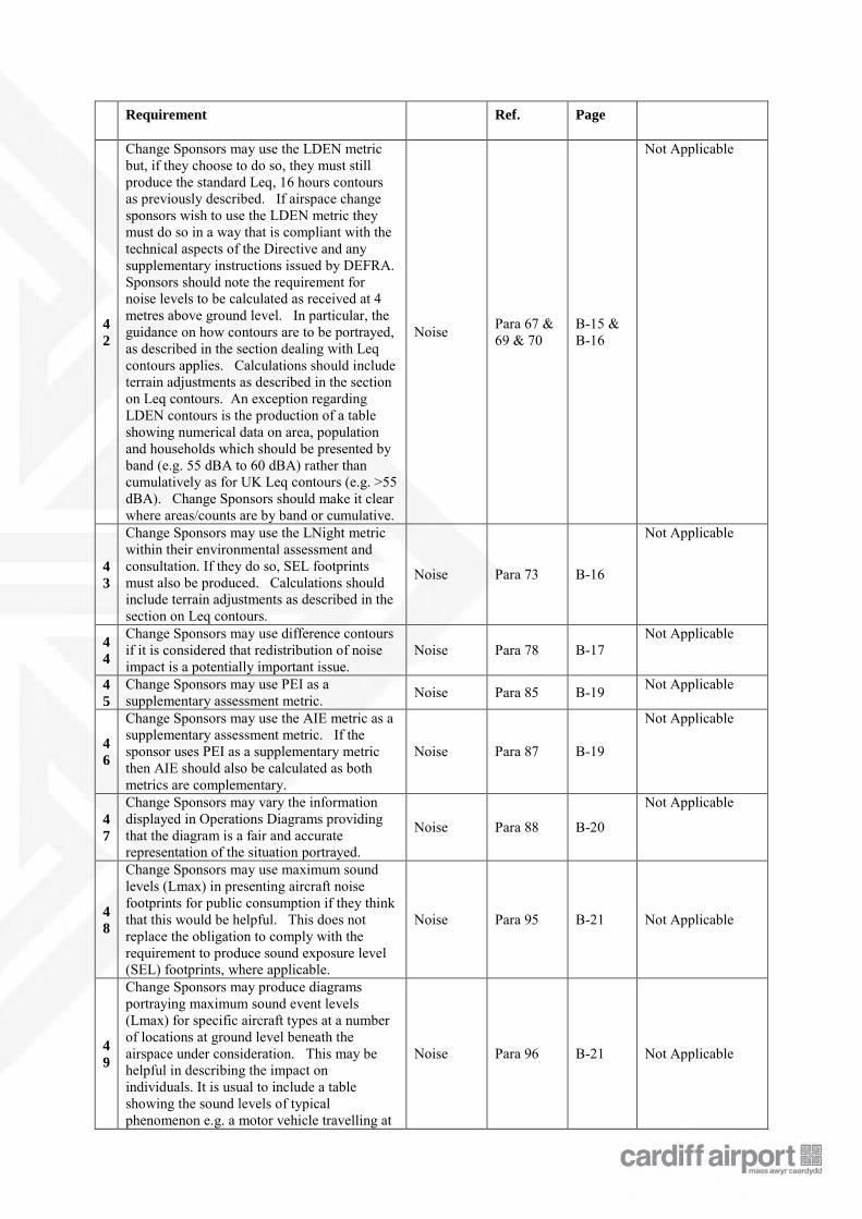
Change Sponsors may use the LDEN metric but, if they choose to do so, they must still produce the standard Leq, 16 hours contours as previously described. If airspace change sponsors wish to use the LDEN metric they must do so in a way that is compliant with the technical aspects of the Directive and any supplementary instructions issued by DEFRA. Sponsors should note the requirement for noise levels to be calculated as received at 4 metres above ground level. In particular, the guidance on how contours are to be portrayed, as described in the section dealing with Leq contours applies. Calculations should include terrain adjustments as described in the section on Leq contours. An exception regarding LDEN contours is the production of a table showing numerical data on area, population and households which should be presented by band (e.g. 55 dBA to 60 dBA) rather than cumulatively as for UK Leq contours (e.g. >55 dBA). Change Sponsors should make it clear where areas/counts are by band or cumulative.
Noise Para 67 & 69 & 70
B-15 & B-16
Not Applicable
4
3
Change Sponsors may use the LNight metric within their environmental assessment and consultation. If they do so, SEL footprints must also be produced. Calculations should include terrain adjustments as described in the section on Leq contours.
Noise Para 73 B-16
Not Applicable
4
4
Change Sponsors may use difference contours if it is considered that redistribution of noise impact is a potentially important issue.
Noise Para 78 B-17 Not Applicable
4
5
Change Sponsors may use PEI as a supplementary assessment metric. Noise Para 85 B-19 Not Applicable
4
6
Change Sponsors may use the AIE metric as a supplementary assessment metric. If the sponsor uses PEI as a supplementary metric then AIE should also be calculated as both metrics are complementary.
Noise Para 87 B-19
Not Applicable
4
7
Change Sponsors may vary the information displayed in Operations Diagrams providing that the diagram is a fair and accurate representation of the situation portrayed.
Noise Para 88 B-20
Not Applicable
4
8
Change Sponsors may use maximum sound levels (Lmax) in presenting aircraft noise footprints for public consumption if they think that this would be helpful. This does not replace the obligation to comply with the requirement to produce sound exposure level (SEL) footprints, where applicable.
Noise Para 95 B-21 Not Applicable
4
9
Change Sponsors may produce diagrams portraying maximum sound event levels (Lmax) for specific aircraft types at a number of locations at ground level beneath the airspace under consideration. This may be helpful in describing the impact on individuals. It is usual to include a table showing the sound levels of typical phenomenon e.g. a motor vehicle travelling at
Noise Para 96 B-21 Not Applicable
Requirement Ref. Page
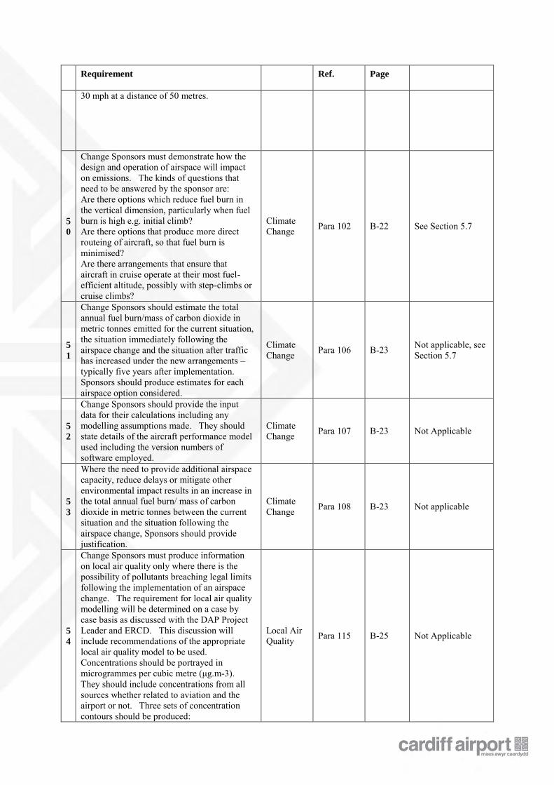
30 mph at a distance of 50 metres.
5
0
Change Sponsors must demonstrate how the design and operation of airspace will impact on emissions. The kinds of questions that need to be answered by the sponsor are: Are there options which reduce fuel burn in the vertical dimension, particularly when fuel burn is high e.g. initial climb? Are there options that produce more direct routeing of aircraft, so that fuel burn is minimised? Are there arrangements that ensure that aircraft in cruise operate at their most fuel-efficient altitude, possibly with step-climbs or cruise climbs?
Climate Change Para 102 B-22 See Section 5.7
5
1
Change Sponsors should estimate the total annual fuel burn/mass of carbon dioxide in metric tonnes emitted for the current situation, the situation immediately following the airspace change and the situation after traffic has increased under the new arrangements – typically five years after implementation. Sponsors should produce estimates for each airspace option considered.
Climate Change Para 106 B-23 Not applicable, see
Section 5.7
5
2
Change Sponsors should provide the input data for their calculations including any modelling assumptions made. They should state details of the aircraft performance model used including the version numbers of software employed.
Climate Change Para 107 B-23 Not Applicable
5
3
Where the need to provide additional airspace capacity, reduce delays or mitigate other environmental impact results in an increase in the total annual fuel burn/ mass of carbon dioxide in metric tonnes between the current situation and the situation following the airspace change, Sponsors should provide justification.
Climate Change Para 108 B-23 Not applicable
5
4
Change Sponsors must produce information on local air quality only where there is the possibility of pollutants breaching legal limits following the implementation of an airspace change. The requirement for local air quality modelling will be determined on a case by case basis as discussed with the DAP Project Leader and ERCD. This discussion will include recommendations of the appropriate local air quality model to be used. Concentrations should be portrayed in microgrammes per cubic metre (μg.m-3). They should include concentrations from all sources whether related to aviation and the airport or not. Three sets of concentration contours should be produced:
Local Air Quality Para 115 B-25 Not Applicable
Requirement Ref. Page
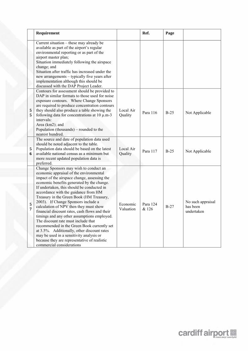
Current situation – these may already be available as part of the airport’s regular environmental reporting or as part of the airport master plan; Situation immediately following the airspace change; and Situation after traffic has increased under the new arrangements – typically five years after implementation although this should be discussed with the DAP Project Leader.
5
5
Contours for assessment should be provided to DAP in similar formats to those used for noise exposure contours. Where Change Sponsors are required to produce concentration contours they should also produce a table showing the following data for concentrations at 10 μ.m-3 intervals: Area (km2); and Population (thousands) – rounded to the nearest hundred.
Local Air Quality Para 116 B-25 Not Applicable
5
6
The source and date of population data used should be noted adjacent to the table. Population data should be based on the latest available national census as a minimum but more recent updated population data is preferred.
Local Air Quality Para 117 B-25 Not Applicable
5
7
Change Sponsors may wish to conduct an economic appraisal of the environmental impact of the airspace change, assessing the economic benefits generated by the change. If undertaken, this should be conducted in accordance with the guidance from HM Treasury in the Green Book (HM Treasury, 2003). If Change Sponsors include a calculation of NPV then they must show financial discount rates, cash flows and their timings and any other assumptions employed. The discount rate must include that recommended in the Green Book currently set at 3.5%. Additionally, other discount rates may be used in a sensitivity analysis or because they are representative of realistic commercial considerations
Economic Valuation
Para 124 & 126 B-27
No such appraisal has been undertaken
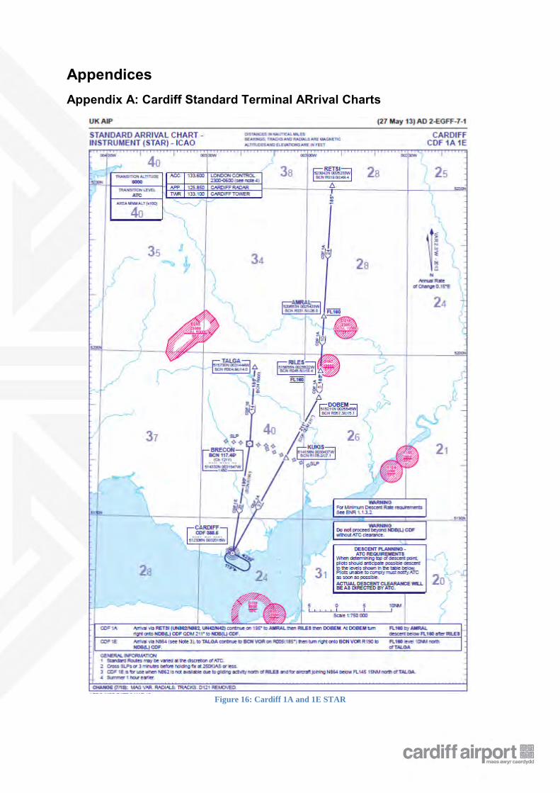
Appendices Appendix A: Cardiff Standard Terminal ARrival Charts
Figure 16: Cardiff 1A and 1E STAR
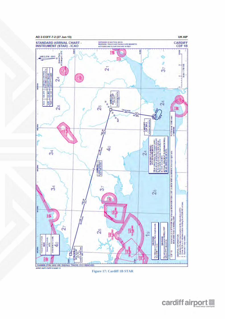
Figure 17: Cardiff 1B STAR
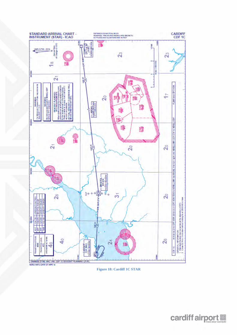
Figure 18: Cardiff 1C STAR
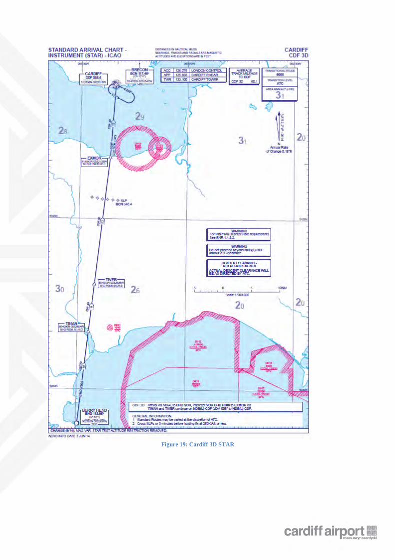
Figure 19: Cardiff 3D STAR
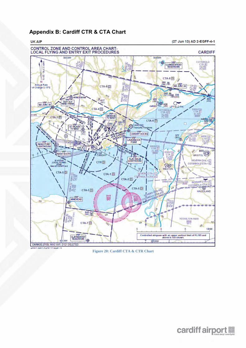
Appendix B: Cardiff CTR & CTA Chart
Figure 20: Cardiff CTA & CTR Chart
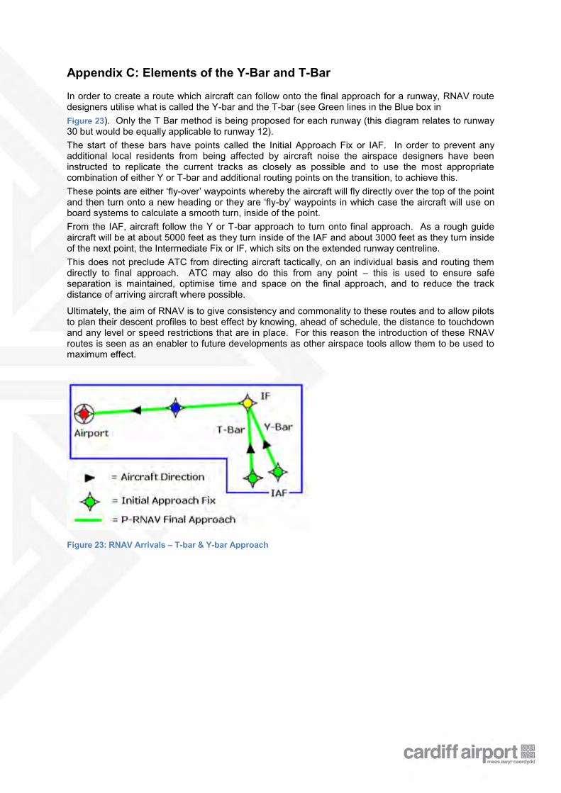
Appendix C: Elements of the Y-Bar and T-Bar In order to create a route which aircraft can follow onto the final approach for a runway, RNAV route designers utilise what is called the Y-bar and the T-bar (see Green lines in the Blue box in Figure 23). Only the T Bar method is being proposed for each runway (this diagram relates to runway 30 but would be equally applicable to runway 12). The start of these bars have points called the Initial Approach Fix or IAF. In order to prevent any additional local residents from being affected by aircraft noise the airspace designers have been instructed to replicate the current tracks as closely as possible and to use the most appropriate combination of either Y or T-bar and additional routing points on the transition, to achieve this. These points are either ‘fly-over’ waypoints whereby the aircraft will fly directly over the top of the point and then turn onto a new heading or they are ‘fly-by’ waypoints in which case the aircraft will use on board systems to calculate a smooth turn, inside of the point. From the IAF, aircraft follow the Y or T-bar approach to turn onto final approach. As a rough guide aircraft will be at about 5000 feet as they turn inside of the IAF and about 3000 feet as they turn inside of the next point, the Intermediate Fix or IF, which sits on the extended runway centreline. This does not preclude ATC from directing aircraft tactically, on an individual basis and routing them directly to final approach. ATC may also do this from any point – this is used to ensure safe separation is maintained, optimise time and space on the final approach, and to reduce the track distance of arriving aircraft where possible.
Ultimately, the aim of RNAV is to give consistency and commonality to these routes and to allow pilots to plan their descent profiles to best effect by knowing, ahead of schedule, the distance to touchdown and any level or speed restrictions that are in place. For this reason the introduction of these RNAV routes is seen as an enabler to future developments as other airspace tools allow them to be used to maximum effect.
Figure 23: RNAV Arrivals – T-bar & Y-bar Approach
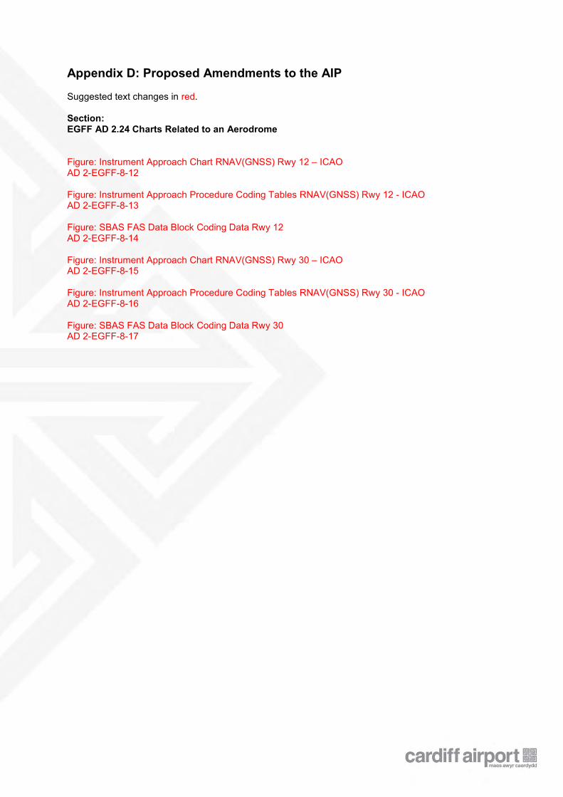
Appendix D: Proposed Amendments to the AIP Suggested text changes in red. Section: EGFF AD 2.24 Charts Related to an Aerodrome Figure: Instrument Approach Chart RNAV(GNSS) Rwy 12 – ICAO AD 2-EGFF-8-12 Figure: Instrument Approach Procedure Coding Tables RNAV(GNSS) Rwy 12 - ICAO AD 2-EGFF-8-13 Figure: SBAS FAS Data Block Coding Data Rwy 12 AD 2-EGFF-8-14 Figure: Instrument Approach Chart RNAV(GNSS) Rwy 30 – ICAO AD 2-EGFF-8-15 Figure: Instrument Approach Procedure Coding Tables RNAV(GNSS) Rwy 30 - ICAO AD 2-EGFF-8-16 Figure: SBAS FAS Data Block Coding Data Rwy 30 AD 2-EGFF-8-17
Appendix E: Flight Validation Plan In accordance with CAP785 "Approval Requirements for Instrument Flight Procedures for Use in UK Airspace" and the CAA Policy Statement "Validation of Instrument Flight Procedures", flight and simulator validation activity is currently planned. British Airways will validate the initial approaches, final approach LNAV and LNAV/VNAV minima and missed approach for both procedures in an A320 series simulator. British Airways will receive draft charts and draft coding tables which they will send to their coding provider who will code them in the standard manner to enable them to be flown in the simulator. This activity will take place prior to submission of the procedure design technical package for approval. There are currently no known carriers with LPV equipped flight simulators in the UK. Therefore the plan is to validate the LPV intermediate, final and missed approach for each procedure using an equipped light aircraft. At this stage it has yet to be determined whether this activity will happen prior to submission of the procedure design technical package for approval. It is being explored whether it is feasible to flight validate these elements using Cobham in a Beech 200 aircraft in the 10 day window prior to the procedures being effective in the AIP when the coding is made available as a result of the short timescales involved.

Appendix F: Consultation Feedback report