Embed Size (px)
Citation preview

Cardinal 5th Wheel Electrical summery.
Model 30TS The electrical system consists to four basic elements. The chassis system is used while the unit is towed. A 12v DC system used for general lighting and other support systems, 110v “House” type electrical system and a Coaxial TV signal distribution system. Chassis System: The Chassis system consists of the necessary electrical components to operate the unit while being towed. Refer to electrical schmaintic # 109709. Power and Ground for the electrical system is supplied to the unit through the “Bargman” plug connected to the tow vehicle. Bargman plug is a six (6) wire type system, Table 1, Figure 1. The chassis system consists of six subsystems:
1. Electrical brake system 2. Clearance/Tail light system 3. Brake light system 4. Turn light system 5. Unit Battery charging system 6. Chassis Ground
Electrical brake system:
Current is supplied to the electric brakes through the vehicle connector. A Black wire runs from the vehicle connector to the electric brakes at each axle. Each brake is grounded via a white wire, which is terminated at the Bargman Junction Box near the front of the chassis.
Each unit is also equipped with a “Break away” brake system. This is a nominally open switch located on the hitch support. The switch is held open with a pin that is attached to a cable. In the event that the tow vehicle and unit is separated the cable that is attached to the tow vehicle pulls the pin from the normally open switch. When the switch closes current flows from the on board battery through the switch to the brake circuit. A full 12v DC is applied to the brakes and the brakes are fully applied. Units are equipped with drum-type electric actuated units that utilize electromagnets and a mechanical linkage. A properly adjusted controller in the tow vehicle provides approximately 2 volts to
Table 1
Connector Wire Color
Function
White Chassis Ground
Yellow Left turn/Stop Brow Right turn/Stop
Red Battery Feed Black Electric Brakes
Green Clearance/Tail light
Figure 1
1

the braking system when the brake pedal is first activated and gradually increases the voltage as brake-pedal pressure is increased. Electerical current from the controller energizes the high-capacity electromagnet in the brakedrum assembly, and the magnet is attracted to the brake-drum armature surface. The magnet is attached to an actuating level and as the magnet is attracted to the drum surface, the rotating force of the wheel moves the lever It rotates an offset cam block against the top of the shoe, forcing the primary shoe outward against the brake-drum surface. Another link - actually the brake-adjuster link - moves the secondary shoe into contact with the brake drum. The level of trailer braking is controlled by the level of current applied to the magnets by the brake controller. Clearance/Tail light system: Each unit is equipped with standard ICC/ FMVSS 108 exterior type lighting. Located at the front top is a series of amber lamps in a typical ICC/ FMVSS 108 layout. Additionally there is an amber light at the forward most point on each sidewall, an amber lamp is also located at near the midpoint on each side as well. At the rear of the unit a standard Red ICC/ FMVSS 108 type lighting arrangement is located across the top. Additionally there is a red lamp located at each side rear corner. All these lamps are supplied current through a Green wire, which terminates at the vehicle connector, Fig 1. The tow Vehicle needs to be able to supply 6 amps to the Clearance/Tail lamp circuit. On all LE models the rear tail lamp is a duel element bulb. All others the tail lamp is a separate lamp assembly. Brake light system, Turn light system At the rear of each unit there is a stop lamp located at the outer rear corner of the rear-facing wall. On all LE models the stop lamp is a duel element bulb in a single lamp assembly with the Tail Lamp. All other’s the brake lamp is a separate lamp assembly. The right Stop/Turn Lamp is control via a Brown wire from the Vehicle connector. Left turn/Stop is controlled via a Yellow wire from the vehicle connector. See Drawing # 109709 for more details. Unit Battery charging system: Each unit is equipped with a means of charging the unit’s 12v DC battery when the unit is connected to the tow vehicle. A 10-gauge wire is routed from the vehicle connector to a 30-amp circuit breaker located in the front trunk. See fig ???? When the vehicle is connected to the unit and the unit’s battery is unbalanced with the tow vehicles charging system current will flow from the tow vehicle through the red wire to the circuit breaker. From the Circuit breaker the current flows to the battery. If any of the unit’s appliances are on (i.e. the refrigerator) the tow vehicle charging system will power the appliances also. The tow vehicle should be equipped with a means of automatically disconnecting the unit’s battery from the main (engine) battery when the engine of the tow vehicle is shut off or in the event of a charging system failure. Chassis Ground The 12v DC chassis system is grounded to the unit near the Bargman cord junction box. A white wire runs from the Vehicle connector to the ground lug near the Bargman cord junction box. In addition a white wire from all the lamps and brakes are grounded at this point. The unit’s battery is grounded via a Black cable from the battery negative (-) to the frame of the chassis.
2
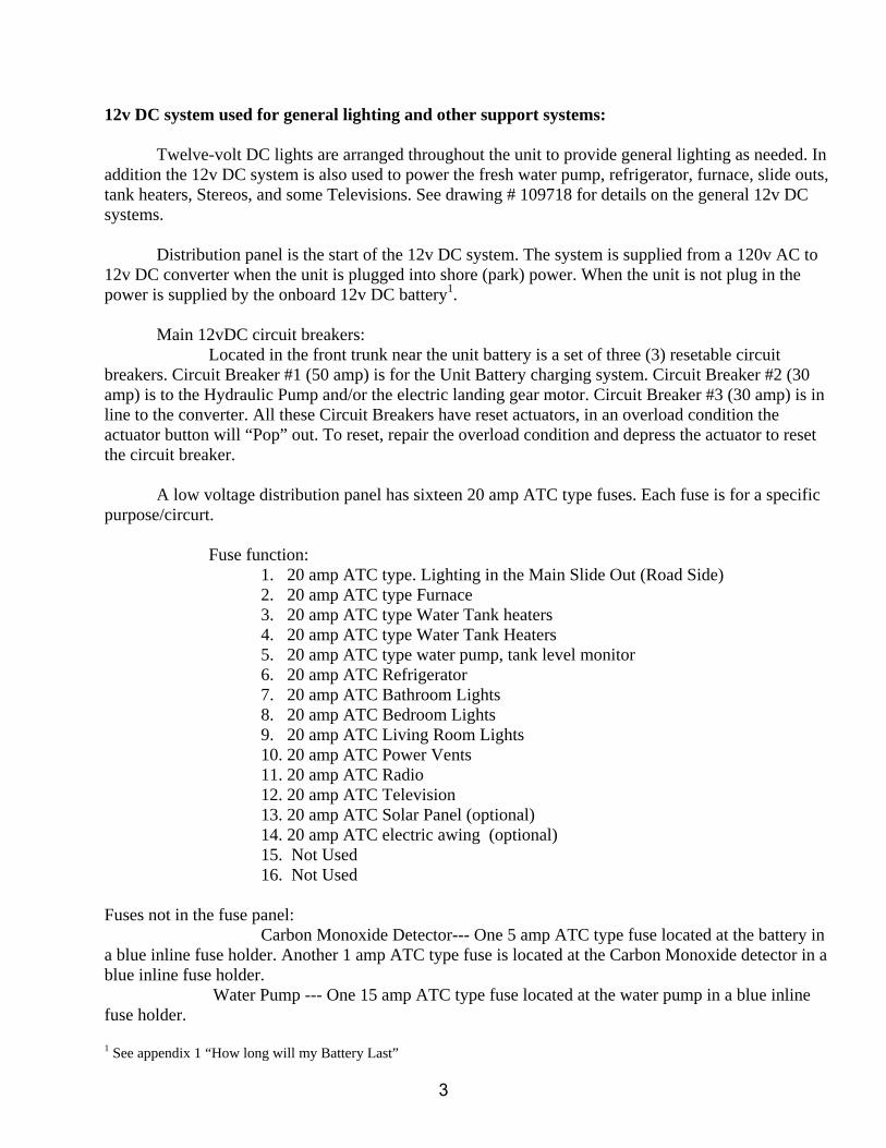
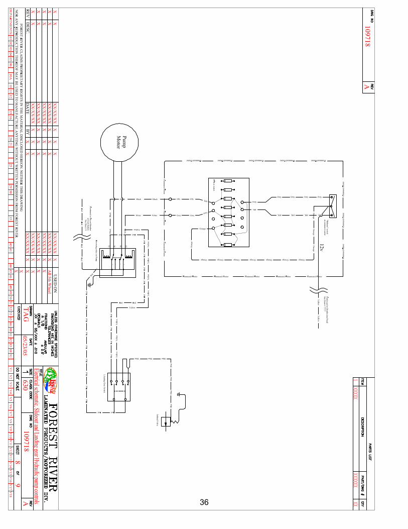
12v DC system used for general lighting and other support systems: Twelve-volt DC lights are arranged throughout the unit to provide general lighting as needed. In addition the 12v DC system is also used to power the fresh water pump, refrigerator, furnace, slide outs, tank heaters, Stereos, and some Televisions. See drawing # 109718 for details on the general 12v DC systems. Distribution panel is the start of the 12v DC system. The system is supplied from a 120v AC to 12v DC converter when the unit is plugged into shore (park) power. When the unit is not plug in the power is supplied by the onboard 12v DC battery1. Main 12vDC circuit breakers: Located in the front trunk near the unit battery is a set of three (3) resetable circuit breakers. Circuit Breaker #1 (50 amp) is for the Unit Battery charging system. Circuit Breaker #2 (30 amp) is to the Hydraulic Pump and/or the electric landing gear motor. Circuit Breaker #3 (30 amp) is in line to the converter. All these Circuit Breakers have reset actuators, in an overload condition the actuator button will “Pop” out. To reset, repair the overload condition and depress the actuator to reset the circuit breaker.
A low voltage distribution panel has sixteen 20 amp ATC type fuses. Each fuse is for a specific purpose/circurt. Fuse function:
1. 20 amp ATC type. Lighting in the Main Slide Out (Road Side) 2. 20 amp ATC type Furnace 3. 20 amp ATC type Water Tank heaters 4. 20 amp ATC type Water Tank Heaters 5. 20 amp ATC type water pump, tank level monitor 6. 20 amp ATC Refrigerator 7. 20 amp ATC Bathroom Lights 8. 20 amp ATC Bedroom Lights 9. 20 amp ATC Living Room Lights 10. 20 amp ATC Power Vents 11. 20 amp ATC Radio 12. 20 amp ATC Television 13. 20 amp ATC Solar Panel (optional) 14. 20 amp ATC electric awing (optional) 15. Not Used 16. Not Used
Fuses not in the fuse panel: Carbon Monoxide Detector--- One 5 amp ATC type fuse located at the battery in a blue inline fuse holder. Another 1 amp ATC type fuse is located at the Carbon Monoxide detector in a blue inline fuse holder. Water Pump --- One 15 amp ATC type fuse located at the water pump in a blue inline fuse holder.
1 See appendix 1 “How long will my Battery Last”
3

Command Center Most function switches for your coach are located on the command center panel. The panel is located in the hallway or near the kitchen. Tank monitors – indicate battery charge, fresh, waste tank and LP
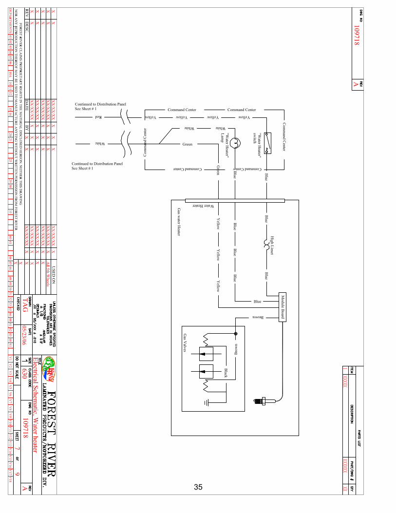
levels. Simply push the button of the level you wish to view. The Water Pump is switched on when using water stored in the fresh water tank. The Water Heater switch on the command center is used when heating water using LP heat. This water heater has an electronic pilot light. Make sure the battery disconnect is on and the LP tank main valve is open. The water heater can also use 110-volt power to heat the water. Refer to the water heater manual for use of your hot water heater. Arctic Pac –See Appendix 2,” for more information.
Slide Room Switches – The number of switches you have will depend on your model. These switches are used to extend and retract the slide outs in the living room and the bedroom areas. Miscellaneous Electrical:
TV Booster – To watch television using the roof antenna, the TV booster should be turned on for the best picture. If your are using a park cable hook-up, switch the TV booster off. LP Leak Detector – Located in the kitchen cabinet base near the door and warns of an LP gas
leak in the coach. The LP leak detector must be on to use any appliances that require LP gas as there is an electronic shut off valve that will stay closed unless the detector is turned on. Disconnect – Some units are equipped with a “Battery Disconnect” located in the cargo compartment just front of the entry door.
4
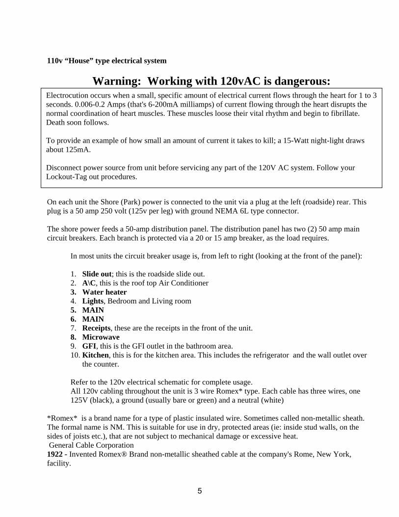
110v “House” type electrical system
Warning: Working with 120vAC is dangerous:
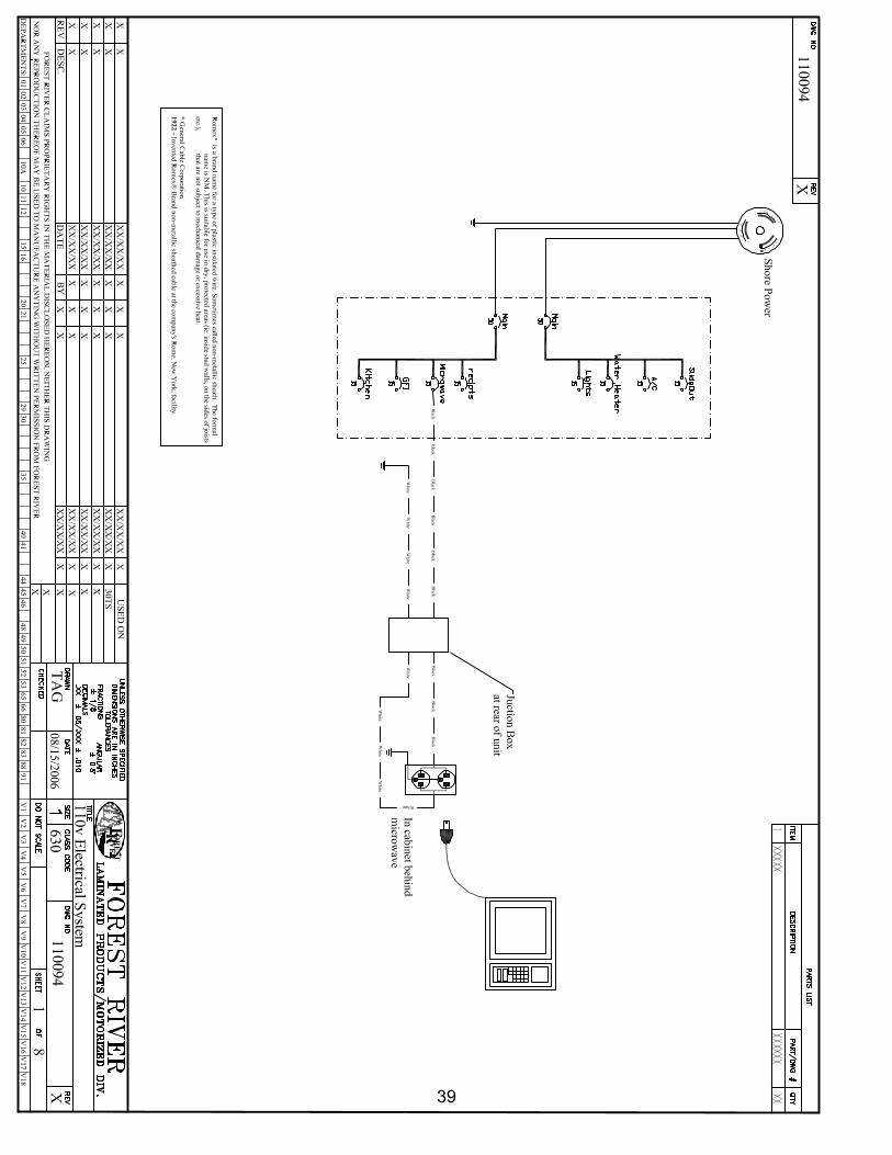
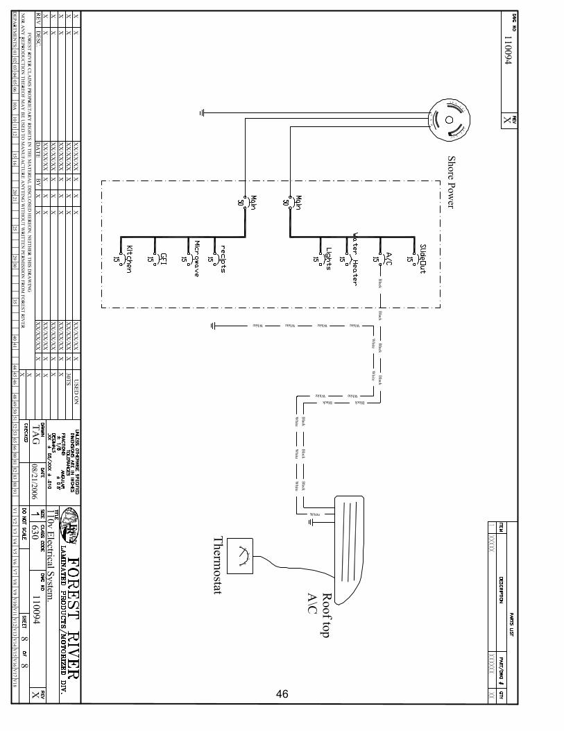
On each unit the Shore (Park) power is connected to the unit via a plug at the left (roadside) rear. This plug is a 50 amp 250 volt (125v per leg) with ground NEMA 6L type connector. The shore power feeds a 50-amp distribution panel. The distribution panel has two (2) 50 amp main circuit breakers. Each branch is protected via a 20 or 15 amp breaker, as the load requires. In most units the circuit breaker usage is, from left to right (looking at the front of the panel):
1. Slide out; this is the roadside slide out. 2. A\C, this is the roof top Air Conditioner 3. Water heater 4. Lights, Bedroom and Living room 5. MAIN 6. MAIN 7. Receipts, these are the receipts in the front of the unit. 8. Microwave 9. GFI, this is the GFI outlet in the bathroom area. 10. Kitchen, this is for the kitchen area. This includes the refrigerator and the wall outlet over
the counter.
Refer to the 120v electrical schematic for complete usage. All 120v cabling throughout the unit is 3 wire Romex* type. Each cable has three wires, one 125V (black), a ground (usually bare or green) and a neutral (white)
*Romex* is a brand name for a type of plastic insulated wire. Sometimes called non-metallic sheath. The formal name is NM. This is suitable for use in dry, protected areas (ie: inside stud walls, on the sides of joists etc.), that are not subject to mechanical damage or excessive heat. General Cable Corporation 1922 - Invented Romex® Brand non-metallic sheathed cable at the company's Rome, New York, facility.
Electrocution occurs when a small, specific amount of electrical current flows through the heart for 1 to 3 seconds. 0.006-0.2 Amps (that's 6-200mA milliamps) of current flowing through the heart disrupts the normal coordination of heart muscles. These muscles loose their vital rhythm and begin to fibrillate. Death soon follows.
To provide an example of how small an amount of current it takes to kill; a 15-Watt night-light draws about 125mA.
Disconnect power source from unit before servicing any part of the 120V AC system. Follow your Lockout-Tag out procedures.
5
11. Coaxial system for TV signal distribution: Each unit can be equipped with up to three (3) POSSIBLE combinations of coaxial for TV signal distribution. See drawing #109708 for schematic details. Terrestrial Antenna and Park hookup.
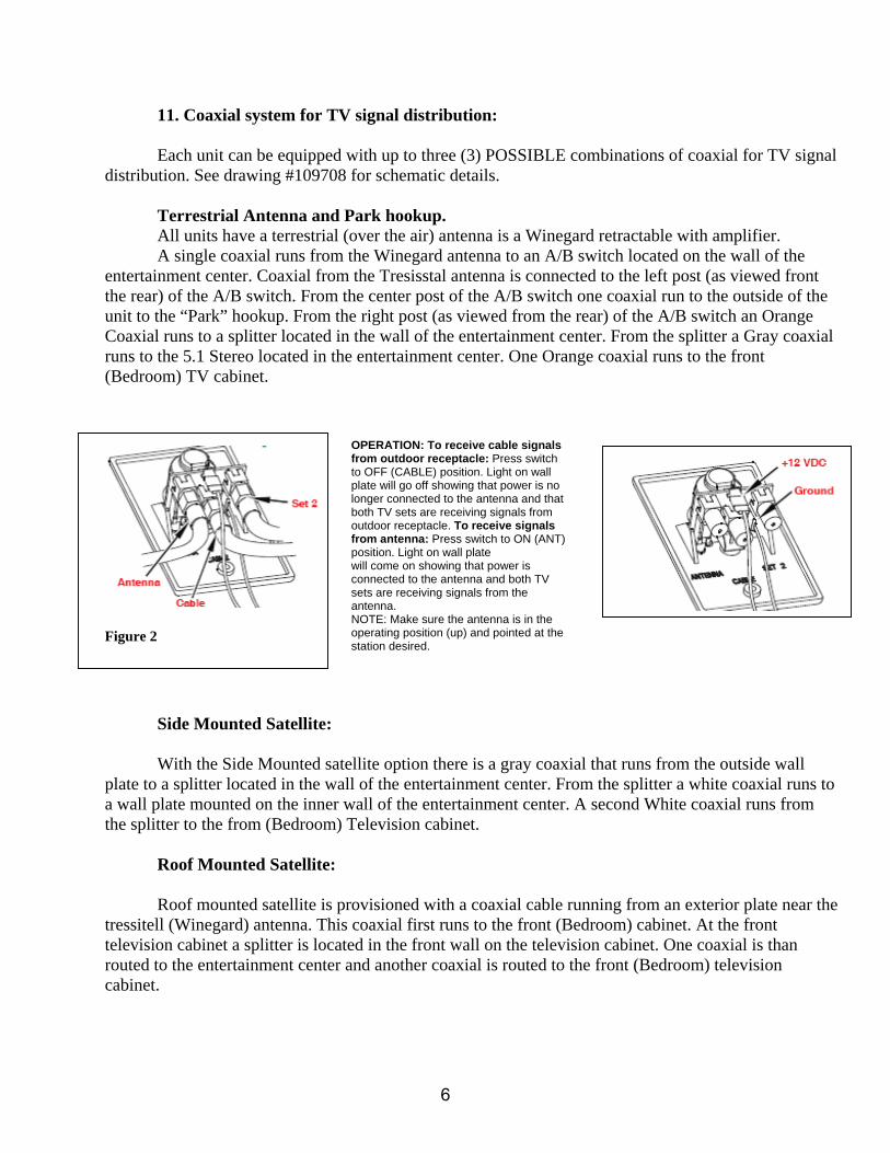
All units have a terrestrial (over the air) antenna is a Winegard retractable with amplifier. A single coaxial runs from the Winegard antenna to an A/B switch located on the wall of the entertainment center. Coaxial from the Tresisstal antenna is connected to the left post (as viewed front the rear) of the A/B switch. From the center post of the A/B switch one coaxial run to the outside of the unit to the “Park” hookup. From the right post (as viewed from the rear) of the A/B switch an Orange Coaxial runs to a splitter located in the wall of the entertainment center. From the splitter a Gray coaxial runs to the 5.1 Stereo located in the entertainment center. One Orange coaxial runs to the front (Bedroom) TV cabinet.
Figure 2
Side Mounted Satellite: With the Side Mounted satellite option there is a gray coaxial that runs from the outside wall plate to a splitter located in the wall of the entertainment center. From the splitter a white coaxial runs to a wall plate mounted on the inner wall of the entertainment center. A second White coaxial runs from the splitter to the from (Bedroom) Television cabinet. Roof Mounted Satellite: Roof mounted satellite is provisioned with a coaxial cable running from an exterior plate near the tressitell (Winegard) antenna. This coaxial first runs to the front (Bedroom) cabinet. At the front television cabinet a splitter is located in the front wall on the television cabinet. One coaxial is than routed to the entertainment center and another coaxial is routed to the front (Bedroom) television cabinet.
OPERATION: To receive cable signals from outdoor receptacle: Press switch to OFF (CABLE) position. Light on wall plate will go off showing that power is no longer connected to the antenna and that both TV sets are receiving signals from outdoor receptacle. To receive signals from antenna: Press switch to ON (ANT) position. Light on wall plate will come on showing that power is connected to the antenna and both TV sets are receiving signals from the antenna. NOTE: Make sure the antenna is in the operating position (up) and pointed at the station desired.
6

Appendix “How long will my Battery Last”
• Reserve capacity minutes (RCM), also referred to as reserve capacity (RC), is a battery's ability to sustain a minimum stated electrical load; it is defined as the time (in minutes) that a lead-acid battery at 80 °F (27 °C) will continuously deliver 25 amperes before its voltage drops below 10.5 volts. The value is calculated by Peukert's equation:
where: C is the theoretical capacity of the battery, I is the current, T is time, and n is the Peukert number, a constant for the given battery. The equation captures the fact that at higher currents, there is less available energy in the battery. The Peukert number is determined empirically and reflects the internal resistance of the battery. To calculate Peukert's exponent for a battery it is discharged twice using two different currents and the time is taken for each. The two currents and the two times are entered into the following equation:
A value close to 1 indicates a well-performing battery with little loss. A higher number reflects a less efficient battery. The Peukert number of a battery is exponential and is between 1.3 and 1.4 for lead acid types*
* From Wikipedia, the free encyclopedia
7

Appendix 1 Arctic Pac Your Forest River recreational vehicle is equipped with a tank heater manufactured by Ultra-heat. The following information describes the purpose, specification, and operation of the tank heater or Arctic PAC. Tank heaters are installed on your recreational vehicle to prevent the holding tanks from freezing.
Fresh Tank (bottom view) Gray or black Tank (bottom view) The following information as described by Ultra-heat 3-96 Ultra-heat Inc. offers two types of “Solid State” heaters that can be secured to holding tanks of different sizes and capacities. The SSTH-1B is designed to be installed on interior holding tanks. The SSTH-2B is designed to be installed on exposed holding tanks. The “SSTH Tank Heaters” may be placed on fresh water tanks, gray water tanks, and black water tanks, any type of tank that you want to protect from freezing. Installation is easy. All SSTH heaters have an adhesive side that can be applied to tanks in all temperatures. The Tank Heater is applied to the lowest point of the holding tank. They are equipped with thermostats that turn on when the temperature of the liquid in the holding tank is 44 degrees F. and turn off when the temperature of the liquid in the holding tank is 64 degrees F. All heaters require 12VDC. The SSTH heaters prevent liquids or wastes from freezing in waste or fresh water systems, in cold temperatures. Recreational Vehicles with an Ultra-Heat tank heater installed on it can be used all year round.
Install the SSTH-1B tank heater on interior holding tanks within insulated areas. When applying the SSTH-1B tank heater to the holding tank, the heater must lay perfectly flat on the tank with no gaps on the sides. Install the SSTH-2B tank heater on exterior holding tanks in non-insulated areas. The heater must lay flat on the tank with no gaps on the sides. Once the tank heater in installed, it is very difficult to remove without damaging the heater.
Specifications: For “SSTH Tank Heater SSTH-18 SSTH-24 SSTH-36 Size… 6.5” x 18” 6.5” x 24” 6.5” x 36” Voltage 12.0VDC 12.0VDC 12.0VDC Amperes 5.46 Amps 6.25 Amps 9.00 Amps Watts 68 Watts 78.8 Watts 108 Watts BTU’s 232 BTU’s 266BTU’s 369 BTU’s Heating Area 117 SQ IN 156 SQ IN 234 SQ IN Thermostat……….All thermostats On at 44 degrees F. and Off at 64 degrees F.
8

Turn on the SSTH-1B tank heater when temperatures are decreasing and above freezing. All tank heaters require 12VDC. Use 16-1 wire with the 18” or 24” tank heaters, and 14-1 wire with the 36” tank heater. When installing more than one tank heater in the tank heater circuit, connect the heaters in parallel. Fuse the tank heater circuit with the appropriate size fuse. Operating instructions: Notice: To insure service with the SSTH-1B Holding Tank Heater some precautions must be taken. When the outside temperatures start to approach freezing, turn on the power to the SSTH-1B Tank Heater. The lighted switch will indicate that there is power to the tank heater circuit. There must be liquid in the holding tank when heater in on. When temperature of the liquid in the holding tank is 44 degrees F, the thermostat on the tank heater will turn on. If the temperature of the tank raises above 66 degrees F, the thermostat will turn the power off, to the tank heater. This prevents the liquid from getting too warm. Turn off the switch for the power to the tank heaters when hooking up to shore power or when starting generator power. This precaution will prevent any damage to the thermostat on the tank heaters. Turn off power to the tank heaters when dumping holding tanks. If possible, check the heater on the holding tanks periodically to insure that the tank heater is in place. Check the wires and the wire connections to the tank heater to insure that they are in place and connected.
9

12v DC system used for general lighting and other support system
28

29

30

31

32

33

34
35
36

110v “House” Electrical System
37

38
39

40

41

42

43

44

45
46