Embed Size (px)
Citation preview

Caress Traditional,Caress Contemporary,Richmond, Rhapsody
& Calypso
INSET LIVE FUEL-EFFECT GAS FIRES
Installation and Maintenance Instructions
Hand these instructions to the owner following installation
Model No’s FICC**MN, FICC**SN, FICC**RN, FDCN**SN & FNCN**SNare only for use on Natural Gas (G20) at a supply pressure of 20mbar in G.B. / I.E.
Model No. FDCN**SP are only for use on Propane Gas (G31) at asupply pressure of 37 mbar in G.B. / I.E.
** denotes trim and fret variant fitted to product

CONTENTSSection 1 Information and Requirements PAGE
1.0 Appliance Information 3-41.1 Conditions of Installation 51.2 Flue and chimney suitability 51.3 Fireplace / surround suitability 61.4 Shelf position 61.5 Chimney inspection 61.6 Fire place opening / catchment space 7-81.7 Fitting to Metal Flue Boxes 91.8 Hearths 91.9 Spillage Monitoring System 9
Section 2 Installation of Fire
2.1 Unpacking the fire 102.2 Installing the fire box 10-182.3 Gas tightness and inlet pressure (MC models) 192.4 Gas tightness and inlet pressure (SC models) 192.5 Gas tightness and inlet pressure (RC models) 20
Section 3 Assembling Fuel Bed and Commissioning
3.1 Assembling the ceramics and fuel bed 21-243.2 Fixing the Infra-red Eye in position 24-253.3 Connecting the battery pack 263.4 Fitting the trim (Rhapsody / Calypso models) 263.5 Fitting the trim (Richmond models) 263.6 Fitting the trim (Caress models) 273.7 Fitting the fender (Rhapsody & Caress contemporary models) 283.8 Fitting the fender (Richmond, Caress traditional & Calypso models) 293.9 Lighting the appliance (Manual control models) 293.10 Lighting the appliance (Slide control models) 303.11 Lighting the appliance (Remote control models) 313.12 Checking for clearance of combustion products 32
Section 4 Maintenance
4.1 Removal of the Burner Assembly (Manual control models) 334.2 Removal of the Piezo Igniter 334.3 Removal of the Control Tap 344.4 Removal of the Pilot Assembly 344.5 Removal of the Burner Assembly (Slide control models) 34-354.6 Removal of the Battery Ignitor 354.7 Repacing the Battery 35-364.8 Removing the Oxy-Pilot Assembly 364.9 Replacing the Control Cable 36-374.10 Removal of the Burner Assembly (Remote control models) 374.11 Removal of the Valve 384.12 Removal of the Oxy-Pilot Assembly 38-394.13 Replacing the Battery 39
This appliance is manufactured by:-
BFM Europe Ltd, Trentham Lakes, Stoke-on-Trent, ST4 4TJ
2

SECTION 1INFORMATION AND REQUIREMENTS
1.0 APPLIANCE INFORMATION
Model FICC**MN (MC) FDCN**SPFICC**SN (SC)FICC**RN (RC)FDCN**SN (SC)FNCN**SN (SC)
Gas Type G20 G31
Main injectors (2 off) Size 260 Size 85
Pilot Type Copreci Copreci21100 / 141 (MC) 21100 / 166 (SC)21100 / 162 (SC & RC)
Max. Gross Heat Input : 6.9 kWMin. Gross Heat Input : 4.2 kW
Cold Pressure : 20.0 mbar +/- 1.0mbar (G20 Models)37.0 mbar +/- 1.0 mbar (G31 Models)
Ignition : Push Button Piezo (MC models)1.5V Battery Generator (SC models)9V Battery Generator (RC models)
Electrode Spark Gap 4.5mm Nominal
Weight (with fender) 24.0 kg Richmond MC22.0 kg Richmond RC20.5 kg Rhapsody Brass & Black18.5 kg Rhapsody Silver21.5 kg Calypso Brass26 kg Caress Traditional MC26.5 kg Caress Traditional SC / RC24.5 kg Caress Contemporary MC25 kg Caress Contemporary SC / RC
3
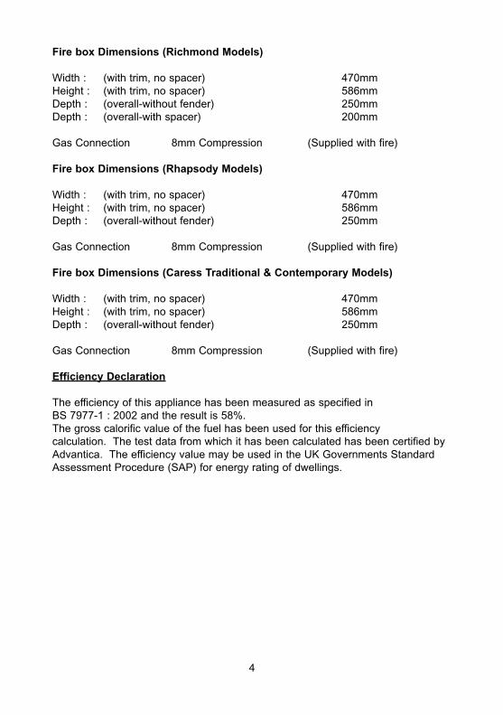
Fire box Dimensions (Richmond Models)
Width : (with trim, no spacer) 470mmHeight : (with trim, no spacer) 586mmDepth : (overall-without fender) 250mmDepth : (overall-with spacer) 200mm
Gas Connection 8mm Compression (Supplied with fire)
Fire box Dimensions (Rhapsody Models)
Width : (with trim, no spacer) 470mmHeight : (with trim, no spacer) 586mmDepth : (overall-without fender) 250mm
Gas Connection 8mm Compression (Supplied with fire)
Fire box Dimensions (Caress Traditional & Contemporary Models)
Width : (with trim, no spacer) 470mmHeight : (with trim, no spacer) 586mmDepth : (overall-without fender) 250mm
Gas Connection 8mm Compression (Supplied with fire)
Efficiency Declaration
The efficiency of this appliance has been measured as specified inBS 7977-1 : 2002 and the result is 58%.The gross calorific value of the fuel has been used for this efficiencycalculation. The test data from which it has been calculated has been certified byAdvantica. The efficiency value may be used in the UK Governments StandardAssessment Procedure (SAP) for energy rating of dwellings.
4

INSTALLATION REQUIREMENTS
1.1 CONDITIONS OF INSTALLATION
It is the law that all gas appliances are installed only by a CORGI RegisteredInstaller, in accordance with these installation instructions and the Gas Safety(Installation and Use) Regulations 1998 as amended. Failure to install appliancescorrectly could lead to prosecution. It is in your own interest and that of safety tocomply with the law.
The installation must also be in accordance with all relevant parts of the Local andNational Building Regulations where appropriate, the Building Regulations(Scotland Consolidation) issued by the Scottish Development Department, and allapplicable requirements of the following British Standard Code of Practice.
1. BS 5871 Part 2 Installation of Inset Live Fuel Effect Gas Fires2. BS 6891 Installation of Gas Pipework3. BS 5440 Parts 1 & 2 Installation of Flues and Ventilation4. BS 1251 Open fire place components5. BS 715 / BS EN 1856-2 Metal flue pipes for gas appliances6. BS 6461 Part 1 Installation of Chimneys and flues7. IS 813 : 1996 Domestic Gas Installation (Republic of Ireland)
No purpose made additional ventilation is normally required for thisappliance, when installed in G.B. When Installing in I.E. please consultdocument I.S. 813 : 1996 Domestic Gas Installation, which is issued by theNational Standards Authority of Ireland. If installing in Northern Ireland,please consult local building regulations. Any purpose made ventilationmust be checked periodically to ensure that it is free from obstruction.
1.2 FLUE AND CHIMNEY SUITABILITY
This appliance is designed for use with conventional brick built or lined chimneysand fabricated flues and metal flue boxes conforming to BS 715 / BS EN 1856-2.All flues must conform to the following minimum dimensions.
Minimum diameter of circular flues 125 mm (Without FlueRestrictor Fitted)
Minimum effective height of all flue types 3 metres
When fitting to conventional chimneys or 175mm flues it may be desirable tofit the flue restrictor baffle (supplied) to reduce the flue flow and increase theefficiency of the fire. Safe clearance of products must always be checked bycarrying out a smoke match test as described.
5
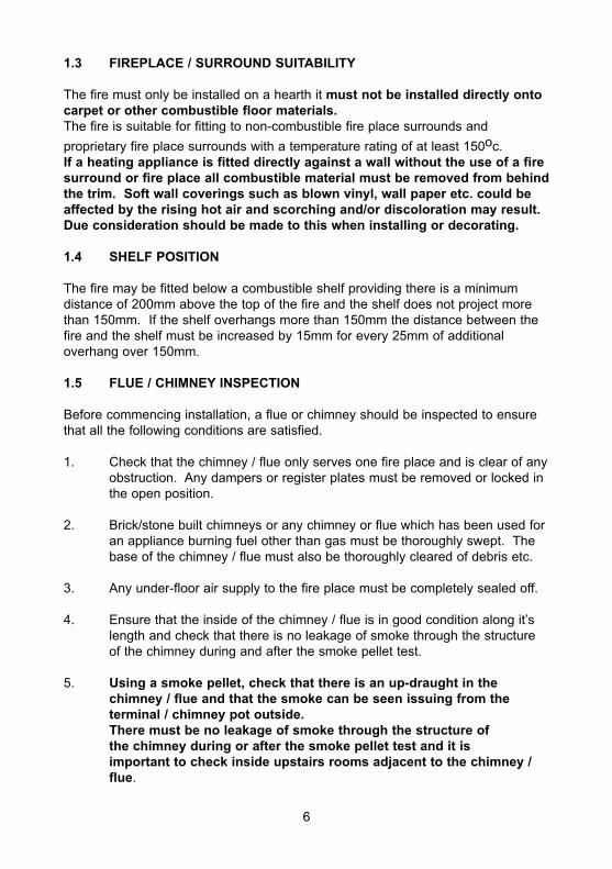
1.3 FIREPLACE / SURROUND SUITABILITY
The fire must only be installed on a hearth it must not be installed directly ontocarpet or other combustible floor materials.The fire is suitable for fitting to non-combustible fire place surrounds and
proprietary fire place surrounds with a temperature rating of at least 150oc.If a heating appliance is fitted directly against a wall without the use of a firesurround or fire place all combustible material must be removed from behindthe trim. Soft wall coverings such as blown vinyl, wall paper etc. could beaffected by the rising hot air and scorching and/or discoloration may result.Due consideration should be made to this when installing or decorating.
1.4 SHELF POSITION
The fire may be fitted below a combustible shelf providing there is a minimumdistance of 200mm above the top of the fire and the shelf does not project morethan 150mm. If the shelf overhangs more than 150mm the distance between thefire and the shelf must be increased by 15mm for every 25mm of additionaloverhang over 150mm.
1.5 FLUE / CHIMNEY INSPECTION
Before commencing installation, a flue or chimney should be inspected to ensurethat all the following conditions are satisfied.
1. Check that the chimney / flue only serves one fire place and is clear of anyobstruction. Any dampers or register plates must be removed or locked inthe open position.
2. Brick/stone built chimneys or any chimney or flue which has been used foran appliance burning fuel other than gas must be thoroughly swept. Thebase of the chimney / flue must also be thoroughly cleared of debris etc.
3. Any under-floor air supply to the fire place must be completely sealed off.
4. Ensure that the inside of the chimney / flue is in good condition along it’slength and check that there is no leakage of smoke through the structureof the chimney during and after the smoke pellet test.
5. Using a smoke pellet, check that there is an up-draught in thechimney / flue and that the smoke can be seen issuing from theterminal / chimney pot outside.There must be no leakage of smoke through the structure ofthe chimney during or after the smoke pellet test and it isimportant to check inside upstairs rooms adjacent to the chimney /flue.
6
Check the chimney pot / terminal and general condition of thebrickwork or masonry. If the chimney or flue is in poor condition or ifthere is no up-draught do not proceed with the installation. If there is ahistory of down-draught conditions with the chimney / flue, a tested andcertificated flue terminal or cowl suitable for the relevant flue type shouldbe considered.
6. A spillage test must always be carried out during commissioning ofthe appliance.
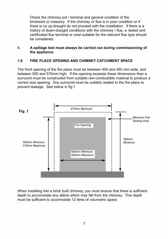
1.6 FIRE PLACE OPENING AND CHIMNEY CATCHMENT SPACE
The front opening of the fire place must be between 400 and 450 mm wide, andbetween 550 and 570mm high. If the opening exceeds these dimensions then asurround must be constructed from suitable non-combustible material to produce acorrect size opening. Any surround must be suitably sealed to the fire place toprevent leakage. See below in fig.1
When installing into a brick built chimney, you must ensure that there is sufficientdepth to accomodate any debris which may fall from the chimney. This depthmust be sufficient to accomodate 12 litres of volumetric space.
Fire Opening
400mm Minimum450mm Maximum
580mmMinimum
470mm MinimumFig. 1
550mm Minimum570mm Maximum
Minimum FlatSealing Area
7
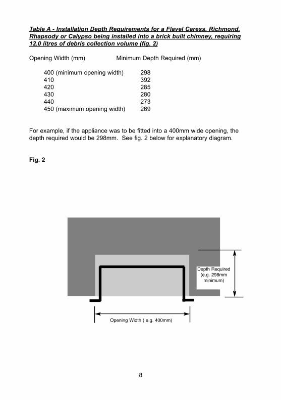
Table A - Installation Depth Requirements for a Flavel Caress, Richmond,Rhapsody or Calypso being installed into a brick built chimney, requiring12.0 litres of debris collection volume (fig. 2)
Opening Width (mm) Minimum Depth Required (mm)
400 (minimum opening width) 298410 392420 285430 280440 273450 (maximum opening width) 269
For example, if the appliance was to be fitted into a 400mm wide opening, thedepth required would be 298mm. See fig. 2 below for explanatory diagram.
Fig. 2
8
Opening Width ( e.g. 400mm)
Depth Required(e.g. 298mmminimum)

1.7 FITTING TO PRE-FABRICATED TWIN WALL METAL FLUE BOXES
The appliance may be fitted to twin wall metal flue boxes conforming to theconstructional requirements of BS 715 / BS EN 1856-2, (for example the SelkirkLFE 175 box). The box must have a minimum flue diameter of 175mm internaland minimum internal dimensions of 300mm deep by 580mm high by 400mmwide. There are no maximum dimensional requirements for the box. The top faceof the box must be insulated with a minimum thickness of 50mm ofnon-combustible mineral wool insulation or similar material. The flue box muststand on a non-combustible base of minimum thickness 12mm.
1.8 HEARTHS
This appliance must only be installed on to a concrete or non-combustible hearth.The hearth material must be a minimum thickness of 13mm with the top surface atleast 50mm above the floor. The hearth must be fitted symmetrically about the fireopening and have a minimum width of 760mm and a minimum projection of300mm forwards from the fire opening. If the appliance is fitted with a black 50mmspacer frame (Richmond models only), then the hearth projection must beincreased to 350mm forwards of the fireplace opening.
1.9 SPILLAGE MONITORING SYSTEM
This appliance is fitted with an atmosphere sensing spillage monitoring system inthe form of an oxygen sensing pilot. This is designed to shut the fire off in theevent of a partial or complete blockage of the flue causing a build up ofcombustion products in the room in which the fire is operated. The following areimportant warnings relating to this spillage monitoring system :-
1) The spillage monitoring system must not be adjusted by the installer.
2) The spillage monitoring system must not be put out of operation.
3) When the spillage monitoring system is exchanged only a complete originalmanufacturers part may be fitted. It is not possible to replace individual parts onthe pilot system on this appliance, only a complete pilot assembly (including thethermocouple) may be fitted.
9
SECTION 2INSTALLATION OF FIRE
2.1 UNPACKING THE FIRE
Carefully lift the fire out of the carton. Remove the loose item packaging carefullyfrom the front of the appliance. Check the contents as listed :-
Packing Check List
1 off Fire box / burner assembly1 off Fender & Ashpan Cover (boxed)1 off L/H & R/H fret mounting brkts (Rhapsody, Calypso & Caress
Contemporary models only)4 off Cast trim mounting brackets and screws1 off Boxed ceramic base, front ceramic rail and 20 coals (18 large, 2 small)
coals1 off Remote control handset (RC models only)1 off Loose items bag1 off each User instruction book and Installation book1 off Battery Pack (RC models only)1 off Metal Trim (Rhapsody, Calypso & Richmond models)1 off Cast Trim (Caress Contemporary & Caress Traditional models)
2.2 INSTALLING THE FIRE BOX
Establish which type of flue you are intending to install the fire in to :-
225 x 225mm (9 inch x 9 inch) brick built chimneys175mm (7 inch) diameter lined brick or stone flue, insulated pre-fabricatedmetal flue box to BS 715 / BS EN 1856-2
When installing into 125mm (5 inch) diameter lined brick or stone flue, orinsulated pre-fabricated metal flue box to BS 715 / BS EN 1856-2. therestrictor baffle must not be fitted.
A spillage test must always be carried out to check satisfactoryclearance of flue products, regardless of the type of flue theappliance is being fitted to.
10
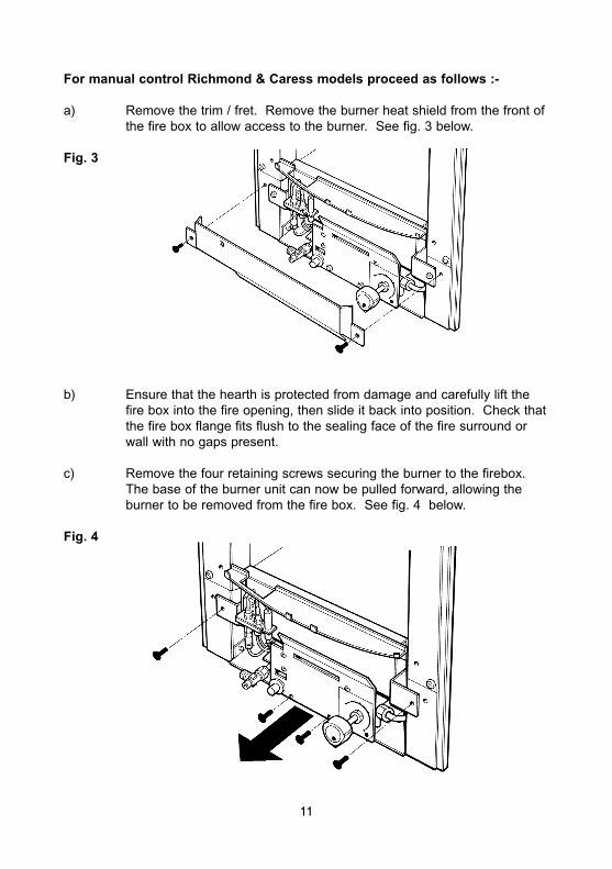
For manual control Richmond & Caress models proceed as follows :-
a) Remove the trim / fret. Remove the burner heat shield from the front ofthe fire box to allow access to the burner. See fig. 3 below.
Fig. 3
b) Ensure that the hearth is protected from damage and carefully lift thefire box into the fire opening, then slide it back into position. Check thatthe fire box flange fits flush to the sealing face of the fire surround orwall with no gaps present.
c) Remove the four retaining screws securing the burner to the firebox.The base of the burner unit can now be pulled forward, allowing theburner to be removed from the fire box. See fig. 4 below.
Fig. 4
11
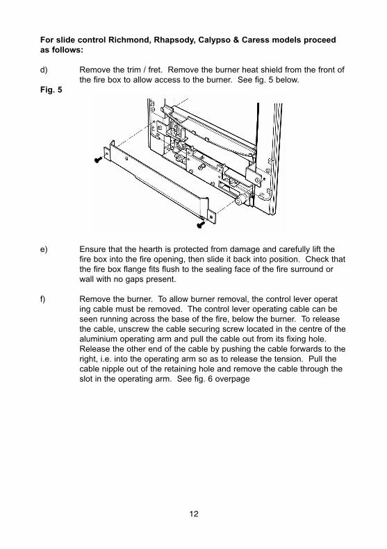
For slide control Richmond, Rhapsody, Calypso & Caress models proceedas follows:
d) Remove the trim / fret. Remove the burner heat shield from the front ofthe fire box to allow access to the burner. See fig. 5 below.
Fig. 5
e) Ensure that the hearth is protected from damage and carefully lift thefire box into the fire opening, then slide it back into position. Check thatthe fire box flange fits flush to the sealing face of the fire surround orwall with no gaps present.
f) Remove the burner. To allow burner removal, the control lever operating cable must be removed. The control lever operating cable can beseen running across the base of the fire, below the burner. To releasethe cable, unscrew the cable securing screw located in the centre of thealuminium operating arm and pull the cable out from its fixing hole.Release the other end of the cable by pushing the cable forwards to theright, i.e. into the operating arm so as to release the tension. Pull thecable nipple out of the retaining hole and remove the cable through theslot in the operating arm. See fig. 6 overpage
12
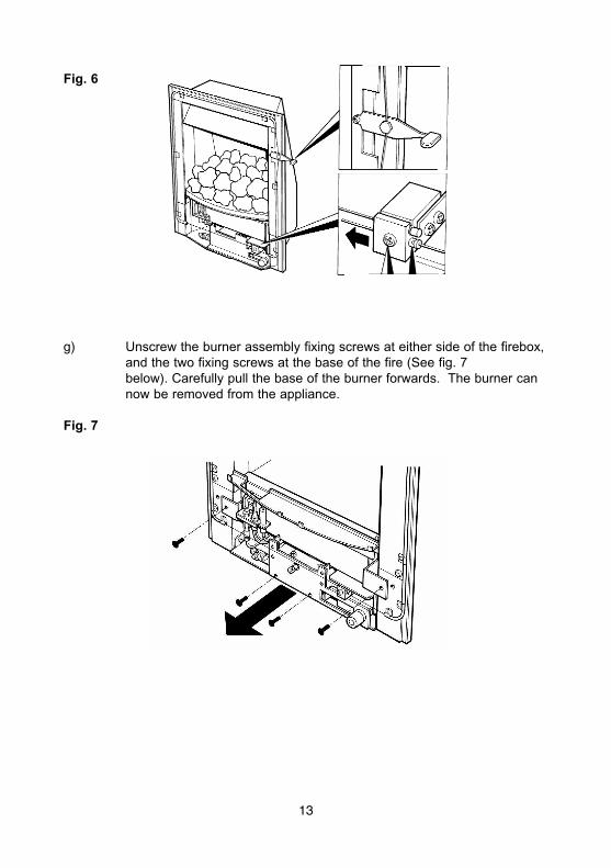
Fig. 6
g) Unscrew the burner assembly fixing screws at either side of the firebox,and the two fixing screws at the base of the fire (See fig. 7below). Carefully pull the base of the burner forwards. The burner cannow be removed from the appliance.
Fig. 7
13

For remote control Richmond & Caress models proceed as follows:
a) Remove the cast trim. Remove the burner heat shield from thefront of the fire box to allow access to the burner. See fig. 8 below.
Fig. 8
b) Ensure that the hearth is protected from damage and carefully lift thefire box into the fire opening, then slide it back into position. Check thatthe fire box flange fits flush to the sealing face of the fire surround orwall with no gaps present.
c) Remove the four retaining screws securing the burner to the firebox.The base of the burner unit can now be pulled forward, allowing theburner to be removed from the fire box. See fig. 9 below.
Fig. 9
14

Continue for all models
Whilst the fire box is still in position, decide which side the gas supply is to enterthe fire from. If concealed pipe work is required plan the pipe run to enter the firebox through one of the openings in the sides of the fire box below the fuelbedsupport panel and connect to the isolating / inlet elbow. The gas connection to theappliance should be made to the isolating / inlet elbow using 8mm rigid tubing.There must be no soldered joints within the firebox. See fig. 10 & 11 below forsuggested concealed pipe layouts.
Fig. 10
Fig. 11
Note : Before breaking into the gas supply a tightness test should be carriedout to establish that the existing pipework is sound.
Carefully withdraw the fire box from the opening to enable the gas supply and firefixing to be completed.
15
Firebox
Fireplace
BuildersOpening
Gas Supply
Firebox
Approx.40mm
Fireplace
Gas Supply
Approx.40mm
BuildersOpening
IMPORTANT NOTE : USE THE FOIL TAPE SUPPLIED TO SEAL THE UNUSEDGAS ENTRY POINTS ON THE FIREBOX. BFM EUROPE WILL NOT ACCEPTGUARANTEE CLAIMS THAT ARE AS RESULT OF THE UNUSED GAS ENTRYPOINTS NOT BEING SEALED.

The preferred method of fixing which is suitable for almost all situations isthe cable fixing method which is described in the following section in detail.
To fit using the preferred cable method proceed as follows-
h) Mark out and drill 4 off No 14 (6mm) holes in the back face of the fireopening in the positions shown below in fig. 12
Fig. 12
Fit the wallplugs provided and screw the fixing eyes securely into the rear of thefire opening.
i) Uncoil the two fire fixing cables and thread one end of each of thecables through one of the two holes on each side of the flue outletshroud.
j) Position the fire carefully on the (protected) surface of the hearth andreach into the fire opening. Thread each of the cables verticallydownwards through the pair of fixing eyes on the same side of the fire.Thread the free end of the cables through the corresponding circularhole on each side of the lower rear of the fire. Carefully slide the firebox back into the fire opening and pull both cables tight.
k) Thread a tensioning screw over each of the cables and ensure that thetensioning nut is screwed fully up against the hexagon shoulder of thetensioning screw (this provides maximum travel for the tensioning nut).
16
20mm
500mm Fireplace Opening100mm
250mm
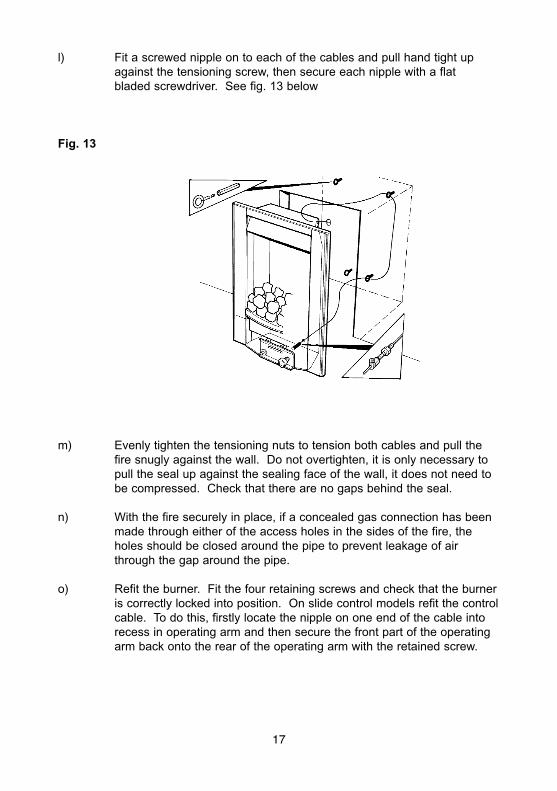
l) Fit a screwed nipple on to each of the cables and pull hand tight upagainst the tensioning screw, then secure each nipple with a flatbladed screwdriver. See fig. 13 below
Fig. 13
m) Evenly tighten the tensioning nuts to tension both cables and pull thefire snugly against the wall. Do not overtighten, it is only necessary topull the seal up against the sealing face of the wall, it does not need tobe compressed. Check that there are no gaps behind the seal.
n) With the fire securely in place, if a concealed gas connection has beenmade through either of the access holes in the sides of the fire, theholes should be closed around the pipe to prevent leakage of airthrough the gap around the pipe.
o) Refit the burner. Fit the four retaining screws and check that the burneris correctly locked into position. On slide control models refit the controlcable. To do this, firstly locate the nipple on one end of the cable intorecess in operating arm and then secure the front part of the operatingarm back onto the rear of the operating arm with the retained screw.
17

This should not be overtightened. Move the control lever fullydownwards and check that the left hand micro-switch operates theigniter and that the control valve spindle is fully depressed. Move thecontrol lever upwards to the “off” position and check that the controllever operates smoothly and safely.
NOTE : The cable is factory set, and therefore should need no adjustment
p) Refit the front burner heat shield to the sides of the fire box (2 Screws)and secure the trim to the fire via the location tabs on the fireboxflange.
q) Before making the final gas connection, thoroughly purge the gassupply pipework to remove all foreign matter, otherwise seriousdamage may be caused to the gas control valve on the fire.
18
2.3 GAS TIGHTNESS AND INLET PRESSURE (MANUAL CONTROLRICHMOND & CARESS MODELS)
a) Remove the pressure test point screw from the inlet elbow and fit amanometer.
b) Turn on the main gas supply and carry out a gas tightness test.
c) Depress the control knob and turn anti-clockwise to the position markedpilot. Hold in the control knob for a few seconds to purge the pipe workthen press the igniter button. The burner should light, continue to holdthe control knob for a few seconds then turn to the full-on position.
d) Check that the gas pressure for Natural Gas (G20) models is 20.0 mbar(+/- 1.0mbar) 8.0 in w.g.(+/- 0.4 in w.g.)
e) Turn off the fire, remove the manometer and refit the pressure test pointscrew. Check the pressure test point screw for gas tightness with theappliance turned on using a suitable leak detection fluid or detector.
2.4 GAS TIGHTNESS AND INLET PRESSURE (SLIDE CONTROLCARESS, RICHMOND, RHAPSODY & CALYPSO MODELS).
a) Remove the pressure test point screw from the pressure test point andfit a manometer.
b) Turn on the main gas supply and carry out a gas tightness test.
c) Depress the control lever to the position marked pilot. Hold down thecontrol lever for a few seconds to purge the pipe work. The burnershould light, continue to hold the control lever for a few seconds to latchthe valve then lift to the full-on position.
d) Check that the gas pressure for Natural Gas (G20) models is 20.0 mbar(+/- 1.0mbar) or for Rhapsody only Propane Gas (G31) models is 37.0mbar (+/- 1.0 mbar)
e) Turn off the fire, remove the manometer and refit the pressure test pointscrew. Check the pressure test point screw for gas tightness with theappliance turned on using a suitable leak detection fluid or detector.
19
2.5 GAS TIGHTNESS AND INLET PRESSURE (REMOTE CONTROLRICHMOND & CARESS MODELS)
a) Remove the pressure test point screw from the inlet elbow and fit amanometer.
b) Turn on the main gas supply and carry out a gas tightness test.
c) Depress both the round buttons on the handset. The fire will thencommence its ignition sequence and will light to high. See page 28 forfull details of the operating method for the fire.
d) Check that the gas pressure is 20.0 mbar (+/- 1.0mbar) 8.0 in w.g.(+/-0.4 in w.g.)
e) Turn off the fire, remove the manometer and refit the pressure test pointscrew. Check the pressure test point screw for gas tightness with theappliance turned on using a suitable leak detection fluid or detector.
20
SECTION 3ASSEMBLING FUEL BED AND COMMISSIONING
3.1 ASSEMBLING THE CERAMICS AND FUEL BED
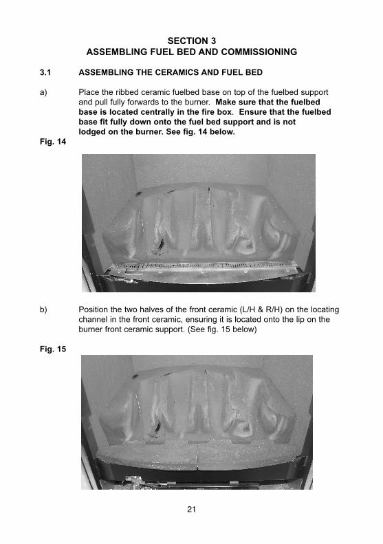
a) Place the ribbed ceramic fuelbed base on top of the fuelbed supportand pull fully forwards to the burner. Make sure that the fuelbedbase is located centrally in the fire box. Ensure that the fuelbedbase fit fully down onto the fuel bed support and is notlodged on the burner. See fig. 14 below.
Fig. 14
b) Position the two halves of the front ceramic (L/H & R/H) on the locatingchannel in the front ceramic, ensuring it is located onto the lip on theburner front ceramic support. (See fig. 15 below)
Fig. 15
21
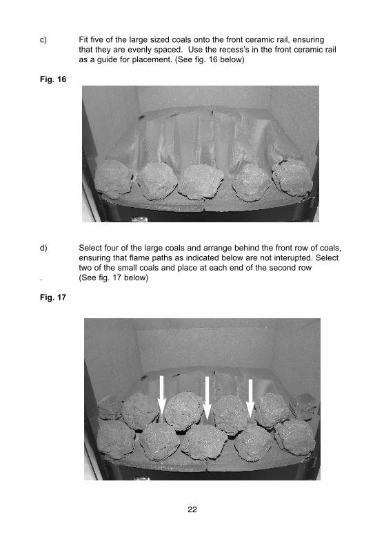
c) Fit five of the large sized coals onto the front ceramic rail, ensuringthat they are evenly spaced. Use the recess’s in the front ceramic railas a guide for placement. (See fig. 16 below)
Fig. 16
d) Select four of the large coals and arrange behind the front row of coals,ensuring that flame paths as indicated below are not interupted. Selecttwo of the small coals and place at each end of the second row
. (See fig. 17 below)
Fig. 17
22
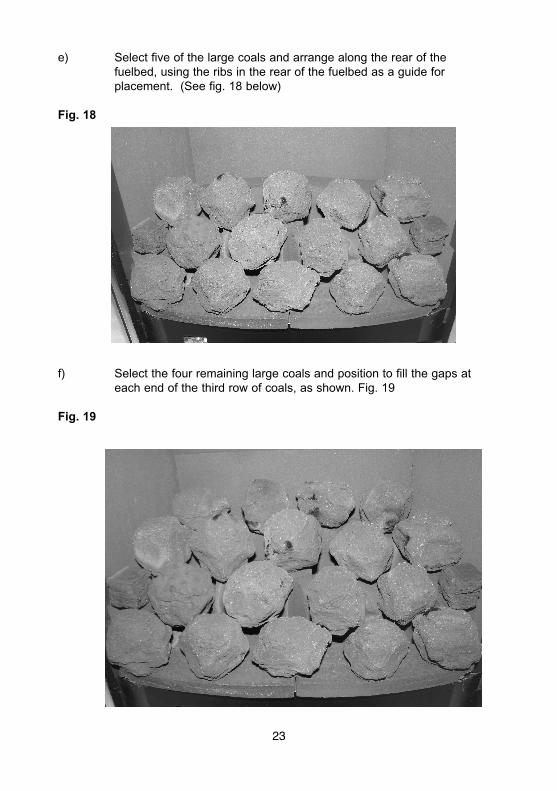
e) Select five of the large coals and arrange along the rear of thefuelbed, using the ribs in the rear of the fuelbed as a guide forplacement. (See fig. 18 below)
Fig. 18
f) Select the four remaining large coals and position to fill the gaps ateach end of the third row of coals, as shown. Fig. 19
Fig. 19
23
The exact position and fit of the coals may be finely adjusted to give the mostpleasing and random appearance.
Warning : Use only the coals supplied with the fire. When replacing thecoals remove the old coals and discard them. Fit a complete set ofcoals of the correct type. Do not fit additional coals or any coalsother than a genuine replacement set.
This appliance uses fuel effect pieces containing Refractory Ceramic Fibres (R.C.F.), which areman-made vitreous silicate fibres. Excessive exposure to these materials may cause temporaryirritation to eyes, skin and respiratory tract. Consequently, it makes sense to take care whenhandling these articles to ensure that the release of dust is kept to a minimum. To ensure that therelease of fibres from these R.C.F. articles is kept to a minimum, during installation & servicing werecommend that you use a HEPA filtered vacuum to remove any dust and soot accumulated in andaround the fire, before and after working on the fire. When replacing these articles werecommend that the replaced items are not broken up, but are sealed within a heavy duty poly-thene bag, clearly labelled as “RCF waste”. This is not classified as “hazardous waste” and maybe disposed of at a tipping site licensed for the disposal of industrial waste. Protective clothing isnot required when handling these arrticles, but we do recommend you follow the normal hygienerules of not smoking, eating or drinking in the work area, and always wash your hands beforeeating or drinking. This appliance does not contain any component manufactured from asbestosor asbestos related products.
3.2 FIXING THE INFRARED SENSOR IN POSITION
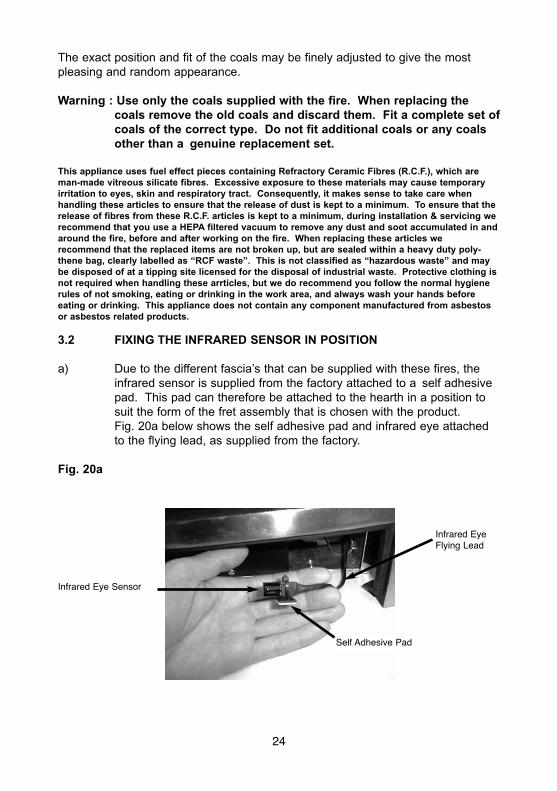
a) Due to the different fascia’s that can be supplied with these fires, theinfrared sensor is supplied from the factory attached to a self adhesivepad. This pad can therefore be attached to the hearth in a position tosuit the form of the fret assembly that is chosen with the product.Fig. 20a below shows the self adhesive pad and infrared eye attachedto the flying lead, as supplied from the factory.
Fig. 20a
24
Infrared EyeFlying Lead
Infrared Eye Sensor
Self Adhesive Pad
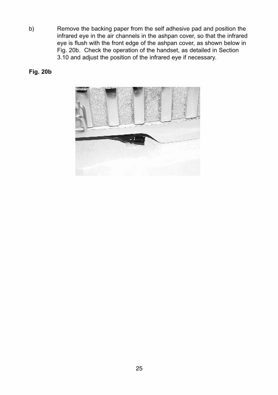
b) Remove the backing paper from the self adhesive pad and position theinfrared eye in the air channels in the ashpan cover, so that the infraredeye is flush with the front edge of the ashpan cover, as shown below inFig. 20b. Check the operation of the handset, as detailed in Section3.10 and adjust the position of the infrared eye if necessary.
Fig. 20b
25

3.3 CONNECTING THE BATTERY PACK
a) To prevent un-necessary battery drain, the battery pack that isused to provide the remote control function for this product isdisconnected at the factory. Prior to attempting to light the product, canthe installer please ensure that the battery pack is re-connected asshown in section b), c) & d) below.
b) Locate the battery pack in the support cradle at the bottom R/H side ofthe firebox / burner assembly.
c) The wire and connecting plug from the battery pack should then beconnected into the supply wire running from the control board. See Fig21 below.
Fig. 21
d) Replace the battery pack into its mounting cradle below the burner.
3.4 FITTING THE TRIM (RHAPSODY / CALYPSO MODELS)
a) Refitting the trim is achieved by locating the rear flange of the trim overthe flange on the firebox mounting face at the top and each side.
3.5 FITTING THE TRIM (RICHMOND MODELS)
a) The trim is held in position on the fixing flange by magnets.
26
BatteryPack
Connecting Wire
ConnectingPlug

3.6 FITTING THE TRIM - CONTEMPORARY & TRADITIONAL CARESSMODELS ONLY
a) Fit the 4 off mounting brackets supplied with the fire in the loose itemspack to the rear face of the Cast-Iron Trim as shown below in Fig. 22
Fig. 22
b) Fit the fascia to the firebox by hooking the mounting brackets into theslots on the firebox as indicated in Fig. 23
Fig. 23
27
4 off MountingBrackets
Image showsbottom right handslot, further slotsare position onmounting flange atopposite side andtop L/H / R/Hmounting flanges
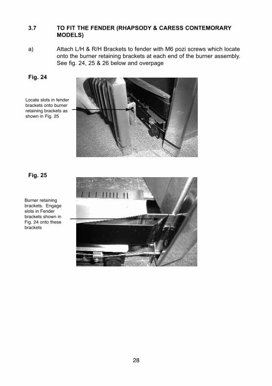
3.7 TO FIT THE FENDER (RHAPSODY & CARESS CONTEMORARYMODELS)
a) Attach L/H & R/H Brackets to fender with M6 pozi screws which locateonto the burner retaining brackets at each end of the burner assembly.See fig. 24, 25 & 26 below and overpage
Fig. 24
Fig. 25
28
Locate slots in fenderbrackets onto burnerretaining brackets asshown in Fig. 25
Burner retainingbrackets. Engageslots in Fenderbrackets shown inFig. 24 onto thesebrackets
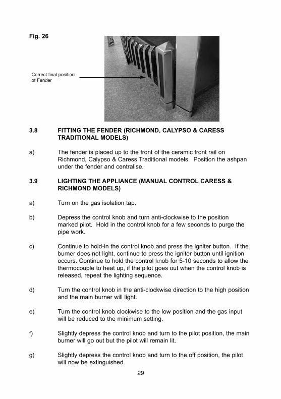
Fig. 26
3.8 FITTING THE FENDER (RICHMOND, CALYPSO & CARESSTRADITIONAL MODELS)
a) The fender is placed up to the front of the ceramic front rail onRichmond, Calypso & Caress Traditional models. Position the ashpanunder the fender and centralise.
3.9 LIGHTING THE APPLIANCE (MANUAL CONTROL CARESS &RICHMOND MODELS)
a) Turn on the gas isolation tap.
b) Depress the control knob and turn anti-clockwise to the positionmarked pilot. Hold in the control knob for a few seconds to purge thepipe work.
c) Continue to hold-in the control knob and press the igniter button. If theburner does not light, continue to press the igniter button until ignitionoccurs. Continue to hold the control knob for 5-10 seconds to allow thethermocouple to heat up, if the pilot goes out when the control knob isreleased, repeat the lighting sequence.
d) Turn the control knob in the anti-clockwise direction to the high positionand the main burner will light.
e) Turn the control knob clockwise to the low position and the gas inputwill be reduced to the minimum setting.
f) Slightly depress the control knob and turn to the pilot position, the mainburner will go out but the pilot will remain lit.
g) Slightly depress the control knob and turn to the off position, the pilotwill now be extinguished.
29
Correct final positionof Fender
3.10 LIGHTING THE APPLIANCE (SLIDE CONTROL CARESS,RHAPSODY, CALYPSO & RICHMOND MODELS)
a) Turn on the isolation valve. Depress the control lever fully downwardsto the position marked. Hold down the control lever for a few seconds toallow the gas to reach the pilot.
b) The fire will then begin its ignition sequence. If the pilot does not light,continue to press the control lever until ignition occurs. The pilot flamecan be seen by looking underneath the front ceramic rail, above theburner heat shield, at the front left hand side of the fuelbed. When thepilot has lit, continue to hold the control lever down for 5-10 seconds toallow the thermocouple to heat up, before releasing the lever apply onefirm downwards push to ensure that the f.s.d. valve is fully latched, ifthe pilot goes out when the control lever is released, repeat the lightingsequence.
c) After lighting, move control lever up to the high position and the mainburner will light. It is recommended that for the most efficientperformance the fire is allowed to warm up for a few minutes with thethe control lever set to high.
d) The gas control can be moved from the High to Low position to give thedesired heat output.
e) To turn the fire off, FULLY raise the control lever to the OFF position.
WARNING : If the fire goes out for any reason or is turned off and itisnecessary to re-light the fire it is important to allow thefire to cool for 3 minutes before attempting to re-light it.
30
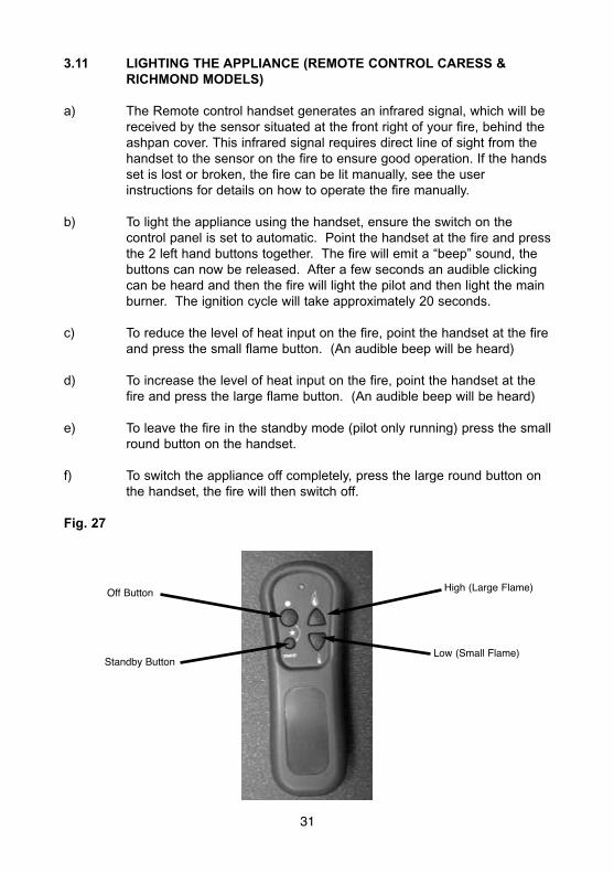
3.11 LIGHTING THE APPLIANCE (REMOTE CONTROL CARESS &RICHMOND MODELS)
a) The Remote control handset generates an infrared signal, which will bereceived by the sensor situated at the front right of your fire, behind theashpan cover. This infrared signal requires direct line of sight from thehandset to the sensor on the fire to ensure good operation. If the handsset is lost or broken, the fire can be lit manually, see the userinstructions for details on how to operate the fire manually.
b) To light the appliance using the handset, ensure the switch on thecontrol panel is set to automatic. Point the handset at the fire and pressthe 2 left hand buttons together. The fire will emit a “beep” sound, thebuttons can now be released. After a few seconds an audible clickingcan be heard and then the fire will light the pilot and then light the mainburner. The ignition cycle will take approximately 20 seconds.
c) To reduce the level of heat input on the fire, point the handset at the fireand press the small flame button. (An audible beep will be heard)
d) To increase the level of heat input on the fire, point the handset at thefire and press the large flame button. (An audible beep will be heard)
e) To leave the fire in the standby mode (pilot only running) press the smallround button on the handset.
f) To switch the appliance off completely, press the large round button onthe handset, the fire will then switch off.
Fig. 27
Off Button High (Large Flame)
Low (Small Flame)Standby Button
31
3.12 CHECKING FOR CLEARANCE OF COMBUSTION PRODUCTS
a) Close all doors and windows in the room.
b) Light the fire and allow to run for approximately 5 minutes on highposition.
c) After approximately 5 minutes hold a smoke match just inside andbelow the centre of the lower front edge of the top of the fire. (It isrecommended that a suitable smoke match holder is used when checking for clearance of combustion products). All smoke generated shouldbe drawn back into the flue. If slight spillage occurs or if in doubt,repeat the test after a further 5-10 minutes. If the test indicates thatspillage is occurring and the flue restrictor baffle has been fitted, itshould be removed and the test repeated after the fire has cooled.
d) If spillage persists, the flue is not functioning correctly and a fault exists.If, after investigation the fault cannot be traced and rectified, the firemust be disconnected from the gas supply and expert advice obtained.
e) If there is an extractor fan fitted any where in the vicinity of theappliance, the spillage test should be repeated with the fan running onmaximum and all interconnecting doors open.
f) After ensuring that the fire is safe to use it should be left on highposition to fully warm up. During this time a slight odour may benoticed, this is due to the “newness” of the fire and will soon disappear.
At this stage any minor adjustments to the coals should be made usingsuitable long handled tongs and taking care not to damage the coals.
Finally, hand the Installation and Maintenance Instructions and theUsers Instructions over to the customer and explain the operation of thefire.
32

SECTION 4MAINTENANCE
Servicing Notes
Servicing should be carried out annually by a competent person such as a CORGIregistered engineer. This is a condition of the Flavel guarantee schemes.The service should include visually checking the chimney and fire opening foraccumulations of debris and a smoke test to check for a positive up-draught in thechimney.The condition of the coals should be checked and if necessary the whole setshould be replaced with a genuine replacement set.The burner assembly is designed to be removed as a complete unit for ease ofaccess. After any servicing work a gas tightness check must always becarried out.
Manual Control Richmond & Caress Fires – For Diagrams refer to Section 2
4.1 Removing the burner assembly from the fire.
4.1.1 Prepare work area (lay down dust sheets etc.)
4.1.2 Remove the trim. Lift the fender and ash pan cover out of the way andput them in a safe location. Remove the loose coals from the fuel bedand front ceramic rail. Remove the front ceramic from the rail. Unscrewthe two pozi-driv fixing screws which secure the burner heat shield andremove it from the fire.
4.1.3 Isolate the gas supply and remove the inlet pipe from the applianceinlet elbow. Unscrew and remove the four screws which retain theburner. Remove the burner assembly from the fire.
4.1.4 To refit the burner assembly. Push the base of the control panel fullyinto the fire and secure with the four screws. Refit the gas supply pipeand carry out a gas tightness test. Refit the burner heat shield thenrefit the coals referring to section 3 for the correct coal layout. Thefender and ash pan cover can now be re-positioned. Refit the trim.
4.2 Removing the Piezo Igniter
4.2.1 Remove the burner assembly as in section 4.1
4.2.2 Disconnect the ignition lead from the piezo and unscrew theretaining nut on the rear of the control panel. Withdraw the piezo fromthe front of the control panel. Reassemble in reverse order and carryout a gas tightness test.
33
4.3 Removing the Control Tap from the fire.
4.3.1 Remove the burner assembly as in section 4.1.
4.3.2 Pull the control knob off the control tap spindle.
4.3.3 Loosen and remove the three gas pipe retaining nuts from the controltap and release the ends of the gas pipes from the control tap body.Loosen and remove the thermocouple securing nut from the end of thecontrol tap.
4.3.4 Unscrew the control tap locknut from the front of the control panel andremove the control tap.
4.3.5 To refit a control tap, reassemble in reverse order noting that the controltap locates with a flat in the control panel. Carry out a gas tightnesstest after re-assembly.
4.4 Removing the Oxy-Pilot Assembly
Note : Because this appliance is fitted with an atmosphere sensing ‘Oxy-Pilot’ it is not possible to replace the thermocouple separately, because thethermocouple position is factory set to a tight tolerance. Any replacement ofparts on the pilot requires a complete new pilot assembly.
4.4.1 Remove the burner assembly as in section 4.1
4.4.2 Unscrew and remove the thermocouple retaining nut from the end of thecontrol tap and disconnect the ignition lead from the pilot electrode.
4.4.3 Unscrew and remove the two pozi-driv screws which secure the pilotassembly to the burner. Remove the pilot.
4.4.4 Re-assemble in reverse order and carry out a gas tightness test.
Slide Control Richmond, Rhapsody, Caress & Calypso Fires
4.5 Removal of the burner assembly
4.5.1 Prepare the work area (lay down dust sheets etc,)
4.5.2 Remove the trim. Lift the fender and ash pan cover out of the way andput them in a safe location. Remove all of the loose coals and frontceramic rail. Unscrew the two pozi-drive fixing screws which secure theburner heat shield and remove it from the fire.
34
4.5.3 Isolate the gas supply and remove the inlet pipe from the appliance inletelbow. To allow burner removal, the control lever operating cable mustbe removed. The control lever operating cable can be seen runningacross the base of the fire, below the burner. To release the cable,unscrew the cable securing screw located in the centre of the aluminiumoperating arm and pull the cable out from its fixing hole. Release theother end of the cable by pushing the cable towards the right i.e. intothe operating arm so as to release the tension. Pull the cable nipple outof the retaining hole and remove the cable through the slot in theoperating arm. Remove the two retaining screws at the base of theburner unit, and the screw each side of the burner unit. The base of theburner unit can now be pulled forward, allowing the burner to beremoved outwards and downwards from the fire box. Remove theburner assembly from the fire.
4.5.4 Refit the burner assembly to the firebox by carefully pushing the bottomof the burner back into position. Secure using the two screws into theside frame of the firebox, and two screws into the base.
It is now necessary to refit and correctly tension the operating cable. Todo this, first set the control lever to the horizontal (central position), thisis the position which creates maximum tension in the operating cable.Refit the operating cable to the aluminium operating arm, firstly locatingthe nipple on one end of the cable into recess in operating arm andthen feed the other end through hole in operating arm. Pull the operating cable until it is finger tight and secure with screw into operating arm(do not over-tighten). Move the control lever fully downwards and checkthat the left hand micro-switch operates the igniter and that the controlvalve spindle is fully depressed. Move the control lever upwards to the“off” position and check that the right hand (cut-off) micro-switchoperates. Check that the control lever operates smoothly and safely.Refit the coals as shown in section 3, refit the fender / ashpan coverand trim.
4.6 Removal of the battery ignitor
4.6.1 Remove the burner assembly as above.
4.6.2 Disconnect the ignition lead and 2 off microswitch leads from the igniter.Unscrew the Battery retaining cap and place battery to one side. Thenunscrew igniter retaining ring and remove igniter from panel.Re-assemble in reverse order and carry out a gas tightness test.
4.7 Replacing the battery
4.7.1 Unscrew Battery retaining cap situated at the front right of the fire andremove the battery
35

4.7.2 Replace in the reverse order using a 1.5V AAAlkaline Battery.
4.8 Removing the Oxy-Pilot Assembly
Note: Because this appliance is fitted with an atmosphere sensing ‘Oxy-Pilot’ it is not possible to replace the thermocouple separately, because thethermocouple position is factory set to a tight tolerance. Any replacement ofparts on the pilot requires a complete new pilot assembly.
4.8.1 Remove the burner assembly as in section 4.1
4.8.2 Unscrew and remove the thermocouple retaining nut from the end of thecontrol tap, disconnect the ignition lead from the pilot electrode and thetwo inline leads from the microswitch.
4.8.3 Unscrew and remove the two pozi-drive screws which secure the pilotassembly to the burner. Remove the pilot.
4.8.4 Re-assemble in reverse order and carry out a gas tightness test.
4.9 Replacing the Control Cable
4.9.1 The control lever operating cable can be seen running across the baseof the fire, below the burner. To release the cable, unscrew the cablesecuring screw located in the centre of the aluminium operating armand pull the cable out from its fixing hole. Release the other end of thecable by pushing the cable towards the right i.e. into the operating armso as to release the tension. Pull the cable nipple out of the retaininghole and remove the cable through the slot in the operating arm. Seefig. 28 below.
Fig. 28
36
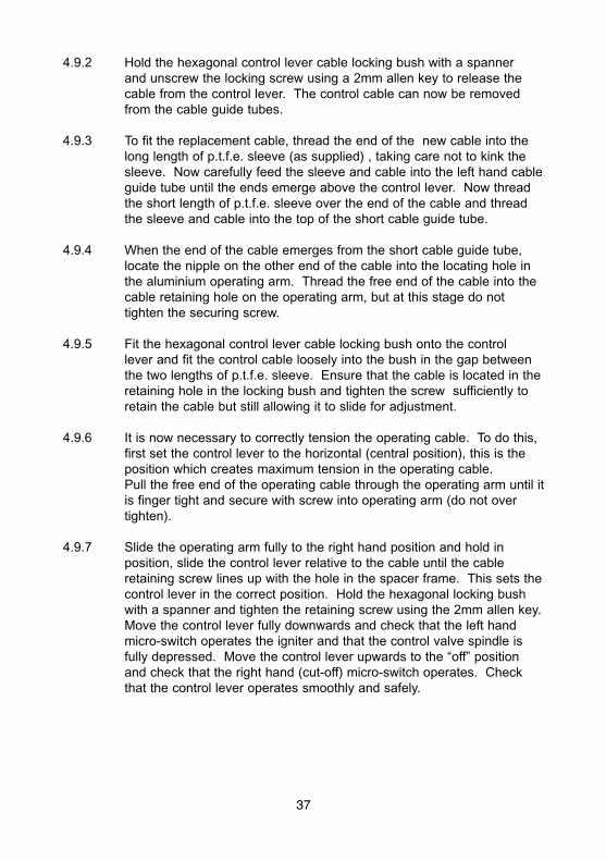
4.9.2 Hold the hexagonal control lever cable locking bush with a spannerand unscrew the locking screw using a 2mm allen key to release thecable from the control lever. The control cable can now be removedfrom the cable guide tubes.
4.9.3 To fit the replacement cable, thread the end of the new cable into thelong length of p.t.f.e. sleeve (as supplied) , taking care not to kink thesleeve. Now carefully feed the sleeve and cable into the left hand cableguide tube until the ends emerge above the control lever. Now threadthe short length of p.t.f.e. sleeve over the end of the cable and threadthe sleeve and cable into the top of the short cable guide tube.
4.9.4 When the end of the cable emerges from the short cable guide tube,locate the nipple on the other end of the cable into the locating hole inthe aluminium operating arm. Thread the free end of the cable into thecable retaining hole on the operating arm, but at this stage do nottighten the securing screw.
4.9.5 Fit the hexagonal control lever cable locking bush onto the controllever and fit the control cable loosely into the bush in the gap betweenthe two lengths of p.t.f.e. sleeve. Ensure that the cable is located in theretaining hole in the locking bush and tighten the screw sufficiently toretain the cable but still allowing it to slide for adjustment.
4.9.6 It is now necessary to correctly tension the operating cable. To do this,first set the control lever to the horizontal (central position), this is theposition which creates maximum tension in the operating cable.Pull the free end of the operating cable through the operating arm until itis finger tight and secure with screw into operating arm (do not overtighten).
4.9.7 Slide the operating arm fully to the right hand position and hold inposition, slide the control lever relative to the cable until the cableretaining screw lines up with the hole in the spacer frame. This sets thecontrol lever in the correct position. Hold the hexagonal locking bushwith a spanner and tighten the retaining screw using the 2mm allen key.Move the control lever fully downwards and check that the left handmicro-switch operates the igniter and that the control valve spindle isfully depressed. Move the control lever upwards to the “off” positionand check that the right hand (cut-off) micro-switch operates. Checkthat the control lever operates smoothly and safely.
37
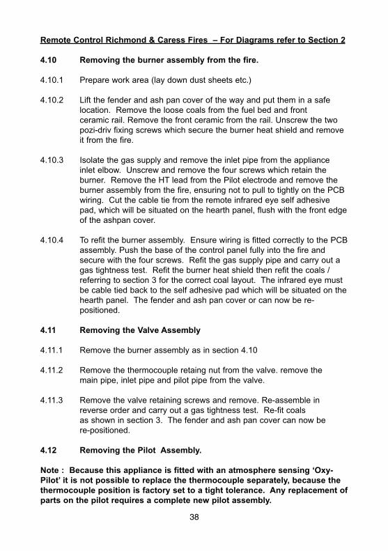
Remote Control Richmond & Caress Fires – For Diagrams refer to Section 2
4.10 Removing the burner assembly from the fire.
4.10.1 Prepare work area (lay down dust sheets etc.)
4.10.2 Lift the fender and ash pan cover of the way and put them in a safelocation. Remove the loose coals from the fuel bed and frontceramic rail. Remove the front ceramic from the rail. Unscrew the twopozi-driv fixing screws which secure the burner heat shield and removeit from the fire.
4.10.3 Isolate the gas supply and remove the inlet pipe from the applianceinlet elbow. Unscrew and remove the four screws which retain theburner. Remove the HT lead from the Pilot electrode and remove theburner assembly from the fire, ensuring not to pull to tightly on the PCBwiring. Cut the cable tie from the remote infrared eye self adhesivepad, which will be situated on the hearth panel, flush with the front edgeof the ashpan cover.
4.10.4 To refit the burner assembly. Ensure wiring is fitted correctly to the PCBassembly. Push the base of the control panel fully into the fire andsecure with the four screws. Refit the gas supply pipe and carry out agas tightness test. Refit the burner heat shield then refit the coals /referring to section 3 for the correct coal layout. The infrared eye mustbe cable tied back to the self adhesive pad which will be situated on thehearth panel. The fender and ash pan cover or can now be re-positioned.
4.11 Removing the Valve Assembly
4.11.1 Remove the burner assembly as in section 4.10
4.11.2 Remove the thermocouple retaing nut from the valve. remove themain pipe, inlet pipe and pilot pipe from the valve.
4.11.3 Remove the valve retaining screws and remove. Re-assemble inreverse order and carry out a gas tightness test. Re-fit coalsas shown in section 3. The fender and ash pan cover can now bere-positioned.
4.12 Removing the Pilot Assembly.
Note : Because this appliance is fitted with an atmosphere sensing ‘Oxy-Pilot’ it is not possible to replace the thermocouple separately, because thethermocouple position is factory set to a tight tolerance. Any replacement ofparts on the pilot requires a complete new pilot assembly.
38
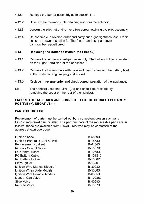
4.12.1 Remove the burner assembly as in section 4.1.
4.12.2 Unscrew the thermocouple retaining nut from the solenoid.
4.12.3 Loosen the pilot nut and remove two screw retaining the pilot assembly.
4.12.4 Re-assemble in reverse order and carry out a gas tightness test. Re-fitcoals as shown in section 3. The fender and ash pan covercan now be re-positioned.
4.13 Replacing the Batteries (Within the Firebox)
4.13.1 Remove the fender and ashpan assembly The battery holder is locatedon the Right Hand side of the appliance .
4.13.2 Remove the battery pack with care and then disconnect the battery leadat the white rectangular plug and socket.
4.13.3 Replace in reverse order and check correct operation of the appliance.
NB The handset uses one LR61 (9v) and should be replaced byremoving the cover on the rear of the handset.
ENSURE THE BATTERIES ARE CONNECTED TO THE CORRECT POLARITYPOSITVE (+), NEGATIVE (-)
PARTS SHORTLIST
Replacement of parts must be carried out by a competent person such as aCORGI registered gas installer. The part numbers of the replaceable parts are asfollows, these are available from Flavel Fires who may be contacted at theaddress shown overpage.
Fuelbed base B-58690Fuelbed front rails (L/H & R/H) B-18730Replacement coal set B-61340RC Gas Control Valve B-106790RC Control Board B-106800RC Battery Cable B-106810RC Battery Holder B-106820Piezo Igniter B-1320Ignition Wire Manual Models B-39030Ignition Wires Slide Models B-50380Ignition Wire Remote Models B-63650Manual Gas Valve B-102880Slide Valve B-40980Remote Valve B-106790
39

Due to our policy of continual improvement and development the exactaccuracy of illustrations and descriptions contained in this book cannot beguaranteed
Part No. B-106530Issue 5
BFM Europe Ltd.Trentham LakesStoke-on-TrentStaffordshireST4 4TJ
www.bfm-europe.com
Telephone - General Enquiries : (01782) 339000Telephone - Service : (0844) 7700169