Embed Size (px)
Citation preview
Magnetic energy harvesting and concentration at distance by
transformation optics
Carles Navau, Jordi Prat-Camps, and Alvaro Sanchez∗
Grup d’Electromagnetisme, Departament de Fısica,
Universitat Autonoma de Barcelona,
08193 Bellaterra, Barcelona, Catalonia, Spain
Abstract
Magnetic energy is one the main agents powering our society: generating energy in power plants,
keeping information in magnetic memories, moving our devices with motors. All of these appli-
cations require a certain spatial distribution of magnetic energy, for example concentrating it in
a transformer core or in a magnetic sensor. We introduce in this work a way to collect magnetic
energy and distribute it in space with unprecedented efficiency and flexibility, allowing very large
concentration of magnetic energy in a free space region, an enhanced magnetic coupling between
two magnetic sources, and the transfer of magnetic energy from a source to a given distant point
separated by empty space. All these features are achieved with a single device, a magnetic shell
designed by transformation optics.
1
arX
iv:1
207.
7030
v1 [
phys
ics.
optic
s] 3
0 Ju
l 201
2
Transformation optics has pushed the possibilities of controlling light towards previously
unexplored limits [1, 2], including perfect lenses [3] and electromagnetic cloaks [4, 5]. When
applied to static magnetic fields [6], transformation optics ideas have allowed unique re-
sults such as the experimental realization of an exact cloak [7]. An important application
of transformation optics is concentration of electromagnetic energy, which is attempted us-
ing plasmonics [8, 9] or macroscopic concentrators [10]. The former only concentrates at
subwavelength scales (typically, nanometers for visible or infrared light [11]) and the latter
requires filling the concentration space with material [10]. Here we apply transformation
optics ideas to shape and concentrate magnetic fields in an unprecedented way. Differently
from the electromagnetic waves case, our device will not require material in its interior so
that it represents an ideal collector for energy harvesting or for increasing the sensitivity
of a magnetic sensor placed inside. The same device surrounding a magnetic source will
enhance the field in the exterior. The combination of these two features allows to transfer
the magnetic energy from a source to a desired distant point through free space. We should
remark that this is a unusual effect because, different from the propagating electromagnetic
fields, static magnetic fields naturally decay with the distance from the source (in the typical
case of a magnetic dipole, as one over the third power of the distance). We will show that
other unique properties can be achieved by combining our magnetic device with or without
magnetic sources in their interior; for example, two magnetic sources each surrounded by
our devices get an enhanced magnetic coupling, which may have applications in powerless
transmission of energy.
.
RESULTS
Design of the magnetic shell
Consider an infinitely long (along z-direction) cylindrical shell of interior and exterior radii
R1 and R2, respectively, dividing the space in three domains: interior (ρ < R1), exterior
(ρ > R2) and shell (R1 < ρ < R2) regions. To fulfill our goals, we will demonstrate that it
is sufficient that (i) given a source of magnetic energy in the exterior, the shell concentrates
all the magnetic energy that would be in the material transferring it to the hole, and (ii) if
2
the source is in the interior, the shell energy is transferred to the exterior.
We start by considering the magnetic source in the exterior domain; we want our shell
to transfer all the shell energy into its hole. The required shell material can be determined
by transformation optics technique [1, 2]; linearly compressing the region from ρ = 0 to
ρ = R2 − ξ in the interior domain and potentially expanding the annulus from ρ = R2 − ξ
to ρ = R2 in the shell region (see Supplementary Information Sect. I). In the ξ → 0 limit no
space is left in the shell region which means that all the energy is concentrated inside. As
the exterior space is not transformed, the exterior magnetic field (and energy) distribution
is unaffected. This allows to understand why magnetic energy is totally transferred from the
shell to the hole: exterior magnetic energy is unaltered whereas in the shell energy is zero
(from the transformation it can be seen that B is radial and H angular so its product B ·H,
the magnetic energy density, is zero), so it can only go to the hole. The material in the
shell has to be homogeneous and anisotropic with radial and angular relative permeabilities
µρ →∞ and µθ → 0. Interestingly, despite the interior space is transformed, no material is
needed in the hole (unlike the electromagnetic waves case [10]). For such a shell in a uniform
applied field, the field in the hole is uniform, has the direction of the applied field H0, and
its magnitude is increased with respect to H0 by a factor R2
R1,
HHOL = H0R2
R1
. (1)
Similar results can be obtained for an actual 3D shape, like a spherical shell. The magnetic
behavior of the shell can be seen in Fig. 1a; a large field concentration is achieved inside
while keeping the external field not distorted.
One can arrive to Eq. (1) by another path. From Maxwell equations, we have analytically
solved the general case of a homogeneous and anisotropic shell in a uniform applied field
(see Supplementary Information Sect. III). We remark two results. First, the cases with
µθ = 1/µρ are those that do not distort the external field [12]. Second, for a given R2/R1
ratio, the field in the hole increases when increasing µρ (for fixed µθ) and also when decreasing
µθ (for fixed µρ). The absolute maximum for magnetic field concentration is achieved in the
limit µρ → ∞ and µθ → 0, so it corresponds to a non-distortion case, and has the value
given in Eq. (1).
3
On the practical realization of the magnetic shell
Concerning the practical realization of our device, our concentrator requires µρ →∞ and
µθ → 0; actual materials with such anisotropy do not exist. But an approximation consisting
of an alternation of radially displaced ferromagnetic and superconductor wedges (or even
rectangular prisms) will constitute a natural discretization of the required material as the
ferromagnets will give the large radial permeability and the alternated superconductors will
cancel the angular components of B field, leading to an effective µθ = 0, as demonstrated in
Figs. 1b-d. For a large N -easily achieved in practice with thin sheets- the field in the hole is
very homogeneous and approaches the exact limit. Such superconducting and ferromagnetic
materials are readily available, even commercially. In [7] we fabricated a magnetic cloak
using these two materials, and their ideal behavior was experimentally confirmed for fields
as large as 40mT and liquid nitrogen temperatures (in our present case the permeability of
the magnetic layer should be larger, so permalloy or similar alloys could be used instead).
For small applied field values as required for sensitive magnetic sensors, the behaviour of
the real materials will be very close to the ideal case. For large applied fields, superconductors
have been used to concentrate magnetic energy with standard procedures for applied fields up
to several teslas in magnetic lenses [13], so the applicability of our device for large fields will
be mainly determined by the saturation field of the ferromagnets, at which its permeability
may decrease towards smaller values than needed.
Magnetic concentration and application to magnetic sensors
Our results can be applied to increasing the sensitivity of magnetic sensors, like SQUIDs,
magnetoresistance or Hall sensors. Magnetic concentration is typically used to enhance their
sensitivity [14–19], by either ferromagnetic materials, attracting magnetic flux, or diamag-
netic ones, repelling it, being superconductors the optimum diamagnetic materials. The
usual concentration strategy is based on two superconductors -or two ferromagnets- sepa-
rated by a gap in which flux concentration is produced. We show in Figs. 2a-b a typical
example of concentration of a uniform applied magnetic field in the gap of two supercon-
ducting slabs (assumed ideal, with zero permeability µ [7]). The field gets enhanced at the
edges of the slabs, not only on the gap region but also on the exterior ones. When reducing
4
the slabs thickness, the contribution from the edges adds up and a rather intense magnetic
field develops in the gap (Fig. 2b), although the gap field is not homogeneous but increases
towards the strip edges and decreases at the central region. For our shell with permeabil-
ities µρ → ∞ and µθ → 0, an applied magnetic field will be enhanced homogeneously in
the shell hole by a factor R2
R1(Eq. (1), so a magnetic sensor placed there would detect a
much larger field -increasing its sensitivity by a large known factor. By comparing with the
superconductors case, in our design not only the average field in the hole is always larger
(Fig. 2c), but also the magnetic flux is always constant whereas for the gap strategy the flux
tends to zero (Supplementary Fig. S7) [20], because field lines are mainly diverted toward
the exterior edges when the gap is narrowed. Our concentration design is optimum because
all the magnetic energy enclosed in the material region is totally transferred to the hole.
Another case of interest is for sensing non-uniform fields from nearby magnetic sources, as
in biosensors [21], in measuring human brain response in magnetoencephalography [22, 23]
or for detecting single magnetic microbeads [24]. Often in these situations it is measured
not the field but its gradient, in order to separate the signal of the source from other distant
noise sources. Transformation optics allows to analytically obtain the magnetic field at any
point of the hole and its gradient (Supplementary Information Sect. IB). The gradient be-
comes scaled by a higher power of the radius relation, [(R2/R1)2 for the gradient of a dipolar
source], which makes our concentrator particularly useful for magnetic gradiometers.
Magnetic energy expulsion and concentration at distance
We now study the case when the magnetic source is placed inside; all the magnetic
energy in the shell has to be expelled towards the exterior domain. The required material is
designed by transforming the space so that the shell space is totally pushed out. Interestingly,
applying linear and potential transformations we find that the required shell is exactly the
same homogeneous anisotropic shell with µρ →∞ and µθ → 0 that we designed for energy
concentration above (Supplementary Information Sect. II).
The shell property of transferring all the magnetic energy in the shell to the exterior when
there is a source in the hole is illustrated in Fig. 3. The magnetic energy of a magnetic
dipole (e. g. a small magnet) in free space (Fig. 3a) is distributed to a further radial
distance by enclosing the dipole with our shell (Fig. 3b). It is worth to notice that outside
5
the shell the field is exactly the same that would be if there was a centered dipole in the
empty space, with a magnetic moment enhanced by a factor R2/R1. In particular, this
enhanced magnetic moment can ideally be made arbitrarily large by making R1 arbitrarily
small. Although being counterintuitive, this can be understood if we take into account that
the shell expels the magnetic energy that would be in the shell volume towards the exterior,
and a small R1 implies that the shell extends to points near the dipole, where the energy
density arbitrarily increases.
When adding a second shell at a given far distance, the enhanced field of the first dipole
is harvested by the second shell and concentrated in its hole (Fig. 3c): magnetic energy
has been transferred from the dipole to a desired position through empty space. Analytical
expressions for the field in all these cases are obtained by the corresponding space transfor-
mations (Supplementary Information Eqs. S28 and S13).
DISCUSSION
Many combinations of shells with or without inner sources may be constructed based
on these ideas. As an example with possible interest for applications, we show in Fig. 4
how the magnetic coupling between two dipoles separated by a given free-space gap can be
substantially enhanced by separating them and surrounding them with two of our shells.
This enhanced magnetic coupling may have relevance to power wireless transmission [25],
where a key factor for achieving this goal is to increase the mutual inductive coupling between
the source and the receiver resonators [26]. Although our ideas strictly apply to static fields,
extension to other frequency ranges such as those used in power wireless transmission would
be possible if materials with the required permeability values at such non-zero frequencies
are found, possibly using metamaterials [27].
Another example of interest is shown in Fig. 5, where we present a strategy to increase
the magnetic energy created by a collection of sources (four magnets in this example) in a
region of free space. By surrounding each of the four magnets with our magnetic shells, a
large concentration of magnetic energy is obtained in the central region (red colour in Fig.
5c), with a value much larger than not only that for the original ’naked’ magnets (Fig. 5a)
but also that for the same magnets when they are brought to a closer distance (Fig. 5b).
These ideas could be applied to medical techniques like transcranial magnetic stimulation
6
(TMS) [28], for which large magnetic fields are required at a given position in the brain,
which is not accessible for magnetic sources. As explained in [29], TMS generally targets
superficial cortical regions, and deeper targets, such as the basal ganglia, are beyond the
range of current technology; our ideas may help extend the reach of magnetic fields toward
deeper depths in the body.
Finally, we comment on the main physical idea behind the results in this work. As
mentioned in the introduction, devising new ways of distributing magnetic energy in space
is key for developing new applications and improve existing ones. Superconductors and
ferromagnetic materials have been traditionally used for shaping magnetic fields, separately.
In terms of magnetic energy, both exclude the magnetic energy from their interior (ideal
superconductors because B=0 and ideal ferromagnets because H=0, so that magnetic energy
density B ·H is zero in both cases). Our device, both in the ideal case of a homogeneous
anisotropic material and in its discretized versions (Fig. 1), also expels the magnetic energy
from its interior, because in this case B is always perpendicular to H in the material. The
new property that we exploit in this work is that when the topology is such that the device
divides the space into an exterior and an interior zone (e. g. a hollow cylinder or a sphere),
then the energy of the magnetic field is totally transferred from one domain to the other (e.
g. from an external source to the hole of the cylinder or sphere), contrary to the case of
only superconductors and ferromagnets, where the energy is returned to the domain where
the magnetic sources are (Supplementary Fig. S8). This is the key physical fact that has
allowed the results of this work, and future configurations that may be developed based on
these ideas as well.
METHODS
Numerical calculations
All numerical calculations have been done using the electromagnetics module (magneto-
statics) of Comsol Multiphysics software.
7
Acknowledgements
We thank Spanish Consolider Project NANOSELECT (CSD2007-00041) for financial
support. JPC acknowledges a FPU grant form Spanish Government (AP2010-2556).
Contributions
All authors equally contributed to this work.
Competing financial interests
The authors are inventors on a Universitat Autonoma de Barcelona patent application.
Corresponding author
Alvaro Sanchez ([email protected])
[1] Ward, A. J. and Pendry, J. B. Refraction and geometry in Maxwells equations. J. Mod. Opt.
43, 773 (1996).
[2] Chen H., Chan C. T., and Sheng, P. Transformation optics and metamaterials. Nature Mate-
rials 9, 387 (2010).
[3] Pendry, J. B., Negative refraction makes a perfect lens. Phys. Rev. Lett. 18, 3966 (2000).
[4] Pendry, J. B., Schurig, D., and Smith, D. R. Controlling electromagnetic fields. Science 312,
1780 (2006).
[5] Schurig, D. et al. Metamaterial electromagnetic cloak at microwave frequencies. Science 314 ,
977 (2006).
[6] Wood B. and Pendry J. B. Metamaterials at zero frequency. J. Phys.: Condens. Matter 19,
076208 (2007).
[7] Gomory, F. et al. Experimental Realization of a Magnetic Cloak. Science, 335 1466 (2012).
[8] Schuller J. A., Barnard E. S., Cai W., Jun Y. C., White, J. S., and Brongersma, M. L.
Plasmonics for extreme light concentration and manipulation. Nature Materials 9, 193 (2010).
8
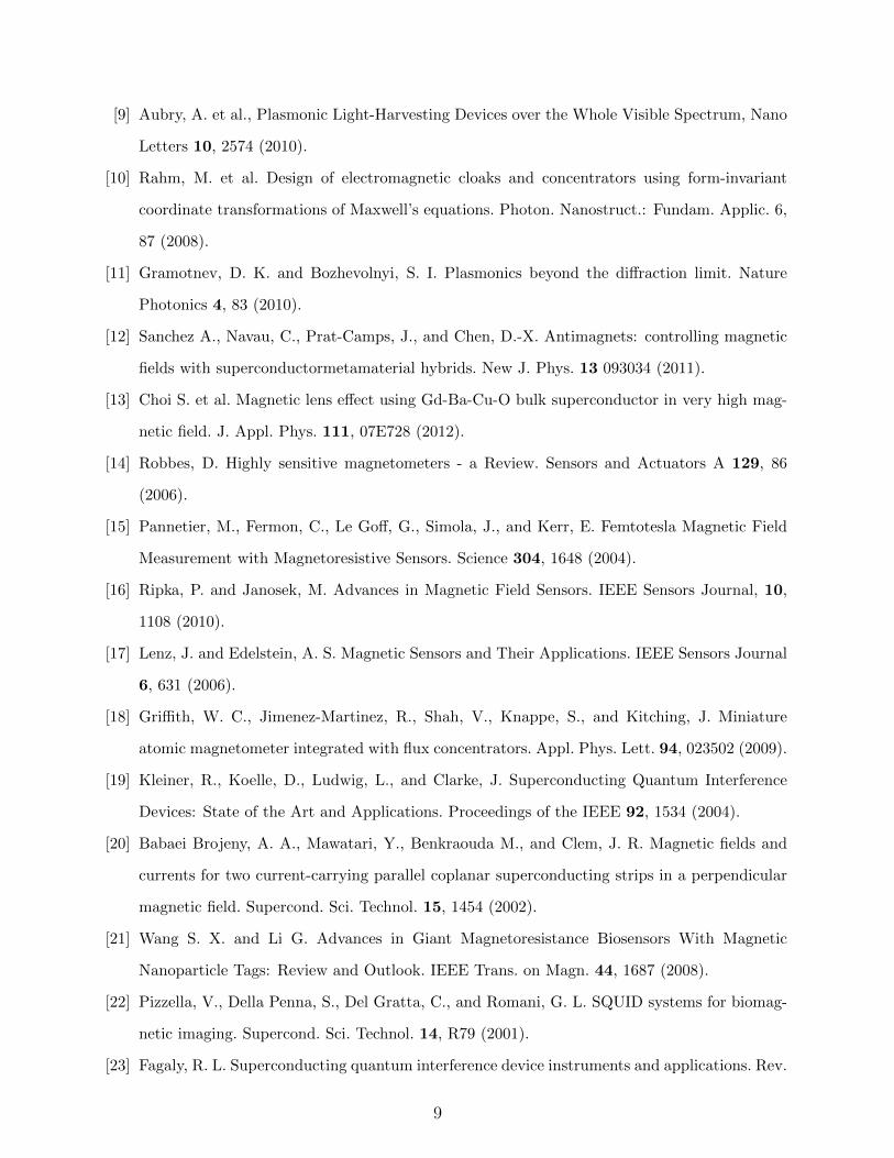
[9] Aubry, A. et al., Plasmonic Light-Harvesting Devices over the Whole Visible Spectrum, Nano
Letters 10, 2574 (2010).
[10] Rahm, M. et al. Design of electromagnetic cloaks and concentrators using form-invariant
coordinate transformations of Maxwell’s equations. Photon. Nanostruct.: Fundam. Applic. 6,
87 (2008).
[11] Gramotnev, D. K. and Bozhevolnyi, S. I. Plasmonics beyond the diffraction limit. Nature
Photonics 4, 83 (2010).
[12] Sanchez A., Navau, C., Prat-Camps, J., and Chen, D.-X. Antimagnets: controlling magnetic
fields with superconductormetamaterial hybrids. New J. Phys. 13 093034 (2011).
[13] Choi S. et al. Magnetic lens effect using Gd-Ba-Cu-O bulk superconductor in very high mag-
netic field. J. Appl. Phys. 111, 07E728 (2012).
[14] Robbes, D. Highly sensitive magnetometers - a Review. Sensors and Actuators A 129, 86
(2006).
[15] Pannetier, M., Fermon, C., Le Goff, G., Simola, J., and Kerr, E. Femtotesla Magnetic Field
Measurement with Magnetoresistive Sensors. Science 304, 1648 (2004).
[16] Ripka, P. and Janosek, M. Advances in Magnetic Field Sensors. IEEE Sensors Journal, 10,
1108 (2010).
[17] Lenz, J. and Edelstein, A. S. Magnetic Sensors and Their Applications. IEEE Sensors Journal
6, 631 (2006).
[18] Griffith, W. C., Jimenez-Martinez, R., Shah, V., Knappe, S., and Kitching, J. Miniature
atomic magnetometer integrated with flux concentrators. Appl. Phys. Lett. 94, 023502 (2009).
[19] Kleiner, R., Koelle, D., Ludwig, L., and Clarke, J. Superconducting Quantum Interference
Devices: State of the Art and Applications. Proceedings of the IEEE 92, 1534 (2004).
[20] Babaei Brojeny, A. A., Mawatari, Y., Benkraouda M., and Clem, J. R. Magnetic fields and
currents for two current-carrying parallel coplanar superconducting strips in a perpendicular
magnetic field. Supercond. Sci. Technol. 15, 1454 (2002).
[21] Wang S. X. and Li G. Advances in Giant Magnetoresistance Biosensors With Magnetic
Nanoparticle Tags: Review and Outlook. IEEE Trans. on Magn. 44, 1687 (2008).
[22] Pizzella, V., Della Penna, S., Del Gratta, C., and Romani, G. L. SQUID systems for biomag-
netic imaging. Supercond. Sci. Technol. 14, R79 (2001).
[23] Fagaly, R. L. Superconducting quantum interference device instruments and applications. Rev.
9

Sci. Instrum. 77, 101101 (2006).
[24] Besse P.-A., Boero G., Demierre M., Pott V., and Popovic, R. Detection of a single magnetic
microbead using a miniaturized silicon Hall sensor. Appl. Phys. Lett. 80, 4199 (2002).
[25] Kurs, A. et al. Wireless Power Transfer via Strongly Coupled Magnetic Resonances. Science
317, 83 (2007).
[26] Huang, D. et al. Magnetic superlens-enhanced inductive coupling for wireless power transfer.
J. Appl. Phys. 111, 064902 (2012).
[27] Wiltshire, M. C. K. et al. Microstructured Magnetic Materials for RF Flux Guides in Magnetic
Resonance Imaging. Science 291, 849 (2001).
[28] Kobayashi, M. and Pascual-Leone, A. Transcranial magnetic stimulation in neurology. Lancet
Neurology 2, 145 (2003).
[29] Bonmassar, G. et al. Microscopic magnetic stimulation of neural tissue. Nat. Comm. 3, 921
(2012).
10
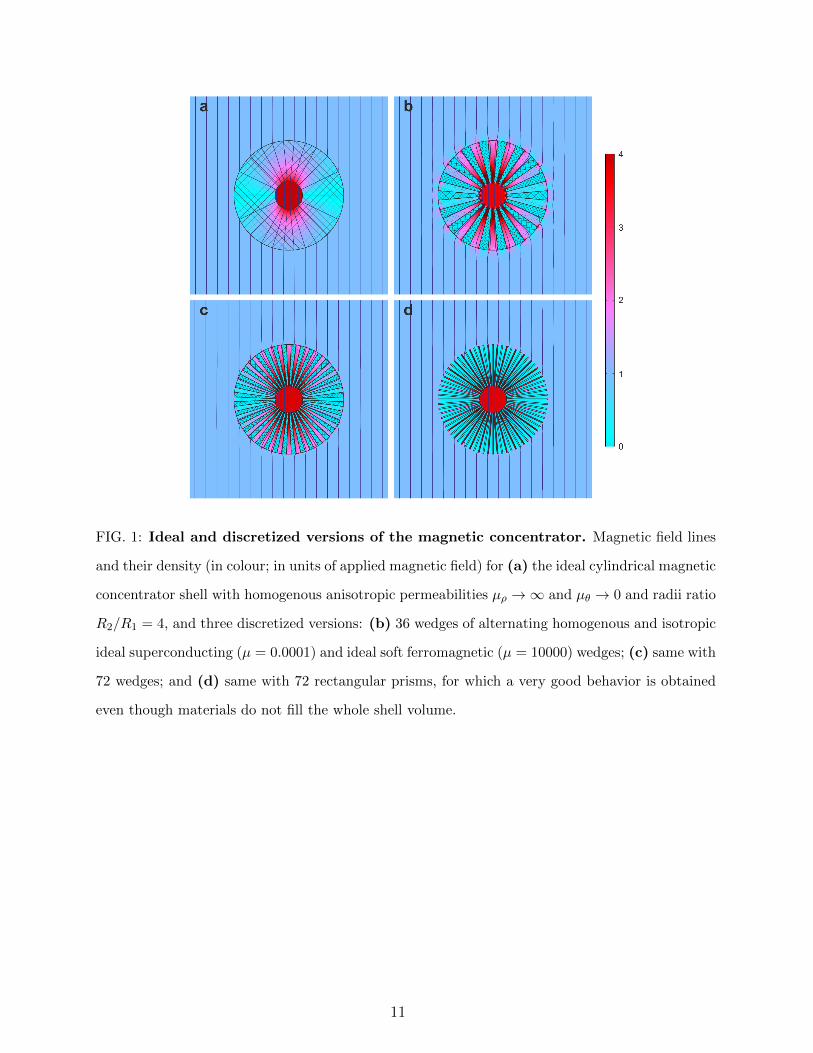
FIG. 1: Ideal and discretized versions of the magnetic concentrator. Magnetic field lines
and their density (in colour; in units of applied magnetic field) for (a) the ideal cylindrical magnetic
concentrator shell with homogenous anisotropic permeabilities µρ →∞ and µθ → 0 and radii ratio
R2/R1 = 4, and three discretized versions: (b) 36 wedges of alternating homogenous and isotropic
ideal superconducting (µ = 0.0001) and ideal soft ferromagnetic (µ = 10000) wedges; (c) same with
72 wedges; and (d) same with 72 rectangular prisms, for which a very good behavior is obtained
even though materials do not fill the whole shell volume.
11
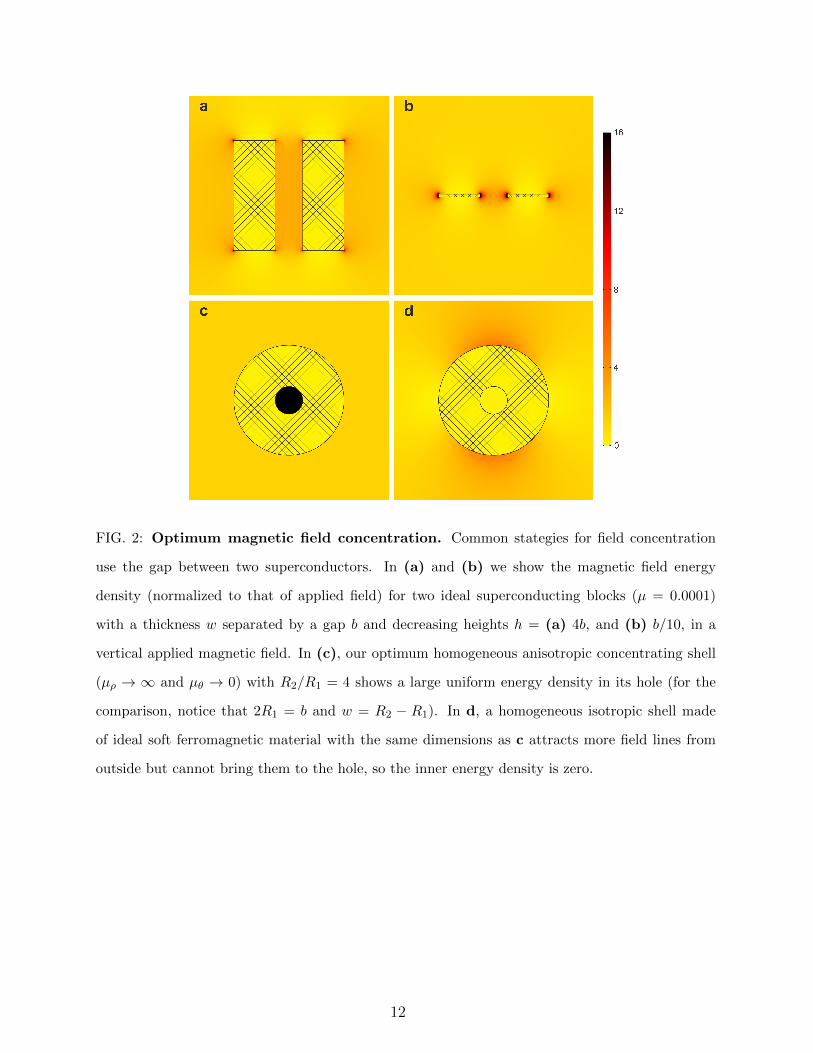
FIG. 2: Optimum magnetic field concentration. Common stategies for field concentration
use the gap between two superconductors. In (a) and (b) we show the magnetic field energy
density (normalized to that of applied field) for two ideal superconducting blocks (µ = 0.0001)
with a thickness w separated by a gap b and decreasing heights h = (a) 4b, and (b) b/10, in a
vertical applied magnetic field. In (c), our optimum homogeneous anisotropic concentrating shell
(µρ → ∞ and µθ → 0) with R2/R1 = 4 shows a large uniform energy density in its hole (for the
comparison, notice that 2R1 = b and w = R2 − R1). In d, a homogeneous isotropic shell made
of ideal soft ferromagnetic material with the same dimensions as c attracts more field lines from
outside but cannot bring them to the hole, so the inner energy density is zero.
12
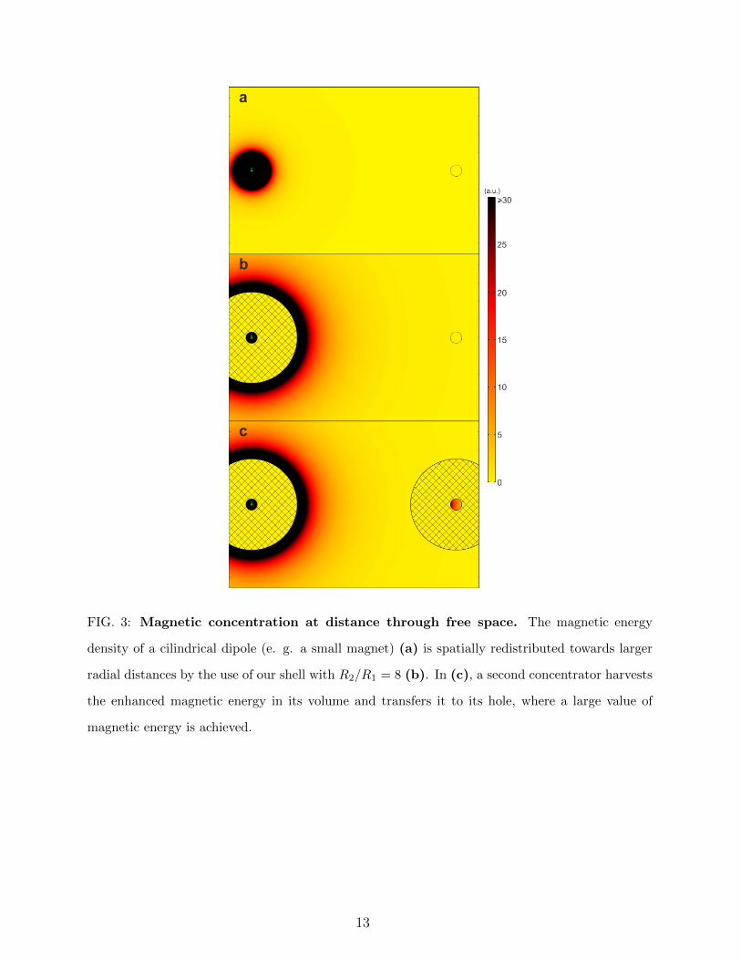
FIG. 3: Magnetic concentration at distance through free space. The magnetic energy
density of a cilindrical dipole (e. g. a small magnet) (a) is spatially redistributed towards larger
radial distances by the use of our shell with R2/R1 = 8 (b). In (c), a second concentrator harvests
the enhanced magnetic energy in its volume and transfers it to its hole, where a large value of
magnetic energy is achieved.
13
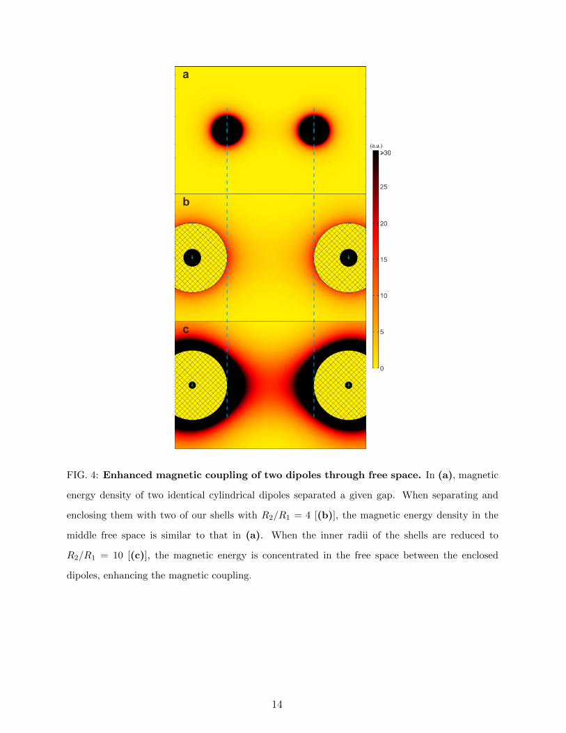
FIG. 4: Enhanced magnetic coupling of two dipoles through free space. In (a), magnetic
energy density of two identical cylindrical dipoles separated a given gap. When separating and
enclosing them with two of our shells with R2/R1 = 4 [(b)], the magnetic energy density in the
middle free space is similar to that in (a). When the inner radii of the shells are reduced to
R2/R1 = 10 [(c)], the magnetic energy is concentrated in the free space between the enclosed
dipoles, enhancing the magnetic coupling.
14
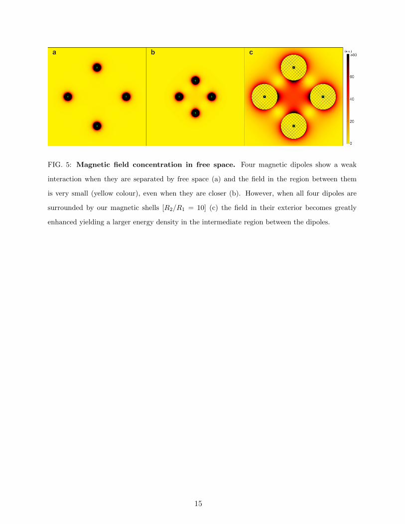
FIG. 5: Magnetic field concentration in free space. Four magnetic dipoles show a weak
interaction when they are separated by free space (a) and the field in the region between them
is very small (yellow colour), even when they are closer (b). However, when all four dipoles are
surrounded by our magnetic shells [R2/R1 = 10] (c) the field in their exterior becomes greatly
enhanced yielding a larger energy density in the intermediate region between the dipoles.
15