Embed Size (px)
Citation preview
1
Carlson Software User Conference 2013
Carlson SurvCE Stakeout
John Gerber, Technical Support
The different data typology found at taking design data out to the field requires special software applications to simplify the stakeout process down to the level of single points positioning. We will see the different stakeout tools available in SurvCE to work with. Points, Lines, Arcs, Offsets, Surfaces, Road Cut/Fill Slopes, and Road Templates. We will also got through the different methodologies applied when using Conventional Total Stations, Robotics or GPS rovers

2
Carlson SurvCE. Stakeout Stakeout settings Located in Job settings / Stake
• Precision value is used to control the decimal precision reported during stakeout routines.
• Store Data Note File: This option specifies whether or not to store the stakeout data in the note file (.NOT) for the current job
• Control File Points have Priority for Stakeout: This option, will give priority to the control file point during stakeout, when the point requested exists in both the current file and the control file.
• Use Automatic Descriptions: This allows you to have point descriptions automatically entered for staked locations based on the settings defined by the Auto Descriptions dialog below
• Alignment Settings contains several parameters to allow controlling stations to stake along the alignment and some other Road applied settings to work with templates and x-sections

3
Cutsheets There can be as many as three cutsheet files active at one time, one for point staking, one for centerline staking and one for slope stake. We can Stake without using cutsheets. The cutsheets activation here enables the writing up of the staked point position at the time of measuring the point (pressing enter). Depending on the type of date we’re staking the staked position will be compared to theoretical one and all the related information defined in format command will be stored in one register for each point. All cutsheet files are ASCII and can be viewed in a text editor or an Excel Spreadsheet.
• Select File to give a name and location for every Point, Alignment and Slope cutsheet file
• Edit File command can be used to edit and review the current cutsheet file.
• Format command allows the user to customize the data headers and order of the different fields in the report
4
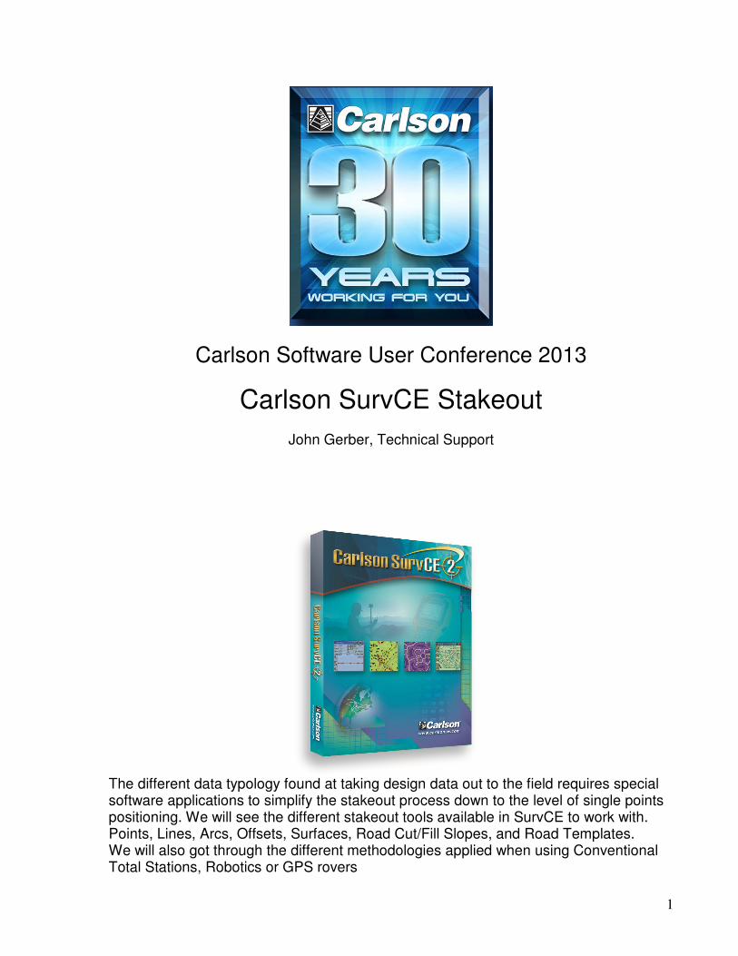
Stake out Tolerance This option you can find at Equipment/ Tolerances menu stands for your position during stake-out as it gets into the circle which radius matches this value, then a ‘target sign’ will be shown around the point to inform about the stake position is now correct within the range of selected tolerance

5
View Point method. Under Equipment/ Configure/ View Point Tab. You can select the Navigation method that is more appropriate for the stake out and your personal preference.
1. In-Out & Left-Right gives the distance differences related to the selected reference
point below. This is mostly used for Total Station. If the In-Out, Left-Right method is selected, then the Ref. Object and Directions From options become available to further define left-right. These last parameters are important considering the point of view while working with robotics (one man) or conventional (two man) total stations
2. North-South, East-West. Most of the GPS rods integrate a compass that can be used to get oriented by the NS/ EW differences given here. When using GPS, this is the best option for the final approach to the point
3. Azimuth and Distance This directs you to the point for stakeout by the total distance and the azimuth, in either the 360 degree circle or a 400 degree circle if configured to grads. This can also be turned into a clock system where North is 12 o’clock
4. Use CL for reference object. If you’re working with a Center Line, forget about the previous methods. This one is really intuitive as we are informed about our position by differences along the CL to the selected station and also indicating the in-out distances to the design offset. I do recommend to keep this option activated.

6
Stake Points This command allows to stakeout a selected point by guiding you to the point position in the field. Point can be selected from its point ID, by selecting the point from the list or picking it from graphics. You can add points to a list from where you can later recall them with Pick from List command. And also you can select a position defined by its polar coordinates Azimuth-Slope-H.Distance to stakeout.
Then just press the Ok command or Enter button to get into the map screen.
A read function is required after sighting the target, to update the directional display information. You should see your points in the map with an icon showing your target location. While in graphics mode stakeout, if you press the down arrow key, you can increase the plan view size and eliminate some of the text information. Pressing the up arrow key again reveals the cut and fill. Depending on the instrument we will get the next software behavior:

7
Total Station Only: After reading and taking the shot, the display will be updated with a distance and direction to the stakeout point. Buttons on the right from top to bottom are Read, Store, Next, Menu, Configure and Setup.
GPS or Robotic Total Station with Tracking On: Your current position is read immediately (no Read button needed).
Once we have entered the stakeout tolerance area, what is indicated by a ‘target’ circular sign.
You have the option now to press Store button. This will make a final shot in case of total station and the Stakeout Report will be displayed. You can turn off the Store Point option, and just reference the Stakeout Report screen for information. If the tolerance distance is exceeded for staking out, you will be notified and asked if you want to continue storing.

8
The coordinates for the Stake Point and the Target Point are displayed. The delta North, East and the elevation difference (Cut/Fill) are also displayed. By pressing OK button now, and If Store Carlson Cutsheet Data in Note File has been enabled, the vertical offset(s) specified will be recorded in the .not file for the job. If under Set Cutsheet Format in the Stakeout section of Job Settings, a Set Pt Cutsheet Format has been established with a named file for storage, then cut and fill data will be saved to a cutsheet ASCII file. If using GPS, the HRMS, VRMS, and PDOP values are also displayed.

9
There is another method to stake points in Robotics or motorized mode. By pressing the configure button/ Search Tab, you will be prompted to activate an automatic turn of the instrument in the direction of the point to be staked. You can also do for automatic vertical turn. This can be used in order to get a direct sight of the point position, sometimes indicated by a laser pointer mark.

10
Here, some important icons available in Stakeout with a Robotic Station
Standby/Search: Robotics only. This status icon shows the instrument is in standby and when pressed, puts the instrument in search mode.
Locked: Robotics only. This icon shows that the instrument is locked, and when pressed, places the robotic total station in Standby mode, meaning it will suspend tracking mode (e.g. allows you to place the pole down, drive a stake, then resume work).
Tracking is On: Robotics only. This icon shows that the instrument is continuously measuring distances (tracking) and when pressed will stop the EDM.
Tracking is Off: Robotics only. This icon shows that the instrument is NOT continuously measuring distances (not tracking) and when pressed will start the EDM.
Prism Mode: This icon shows that the instrument is currently configured to read a prism and when pressed will switch the instrument to reflectorless mode.
Reflectorless Mode: This icon shows that the instrument is currently in reflectorless mode and when pressed will switch the instrument to prism

11
Stake Line/ Arc This command opens a dialog where you can choose between Define Line, Define Alignments, Define Arc (3 points), and Define Arc (PC, PT, Value).
Define Line This command allows you to stakeout to a line between two points by guiding you to the point with a series of commands and directions. Point position can be selected by giving station and offset from the base-line defined by the initial points. This is a good function when staking pipes, concrete trenches or any other kind of building shapes. It also includes the cut / fill information very useful at setting points along the line.

12
Define Alignments (Horizontal) Stakeout Centerline only requires a horizontal alignment, but you have the option to specify a vertical alignment which will lead to cut and fill results as well. Additionally, you can specify a reference alignment. This feature allows you to stake the offset off of one alignment
Define Arc (3 Points) This routine requests three points to define a unique arc, which is then used for stakeout by station and offset. The first point becomes the beginning of the arc.
Define Arc (PC, PT Value) This option for defining the arc requires four input parameters: the Start point, End Point, Curve Direction, and any of the following: Radius Point, Radius Length, Arc Length, Delta Angle or Degree of Curvature.

13
Stake Line/Arc Screen (Station/Offset) Selecting OK on the Define Line, Define Alignments or Define Arc dialogs presents the Stake Line dialog for defining the stake location parameters (e.g. offset or elevation).
• Station: This is where you enter the station to stakeout.
• Station +: You can advance to the next station as defined by the alignment points or station interval using the right green arrow icon.
• Station -: You can go back to the previous station as defined by the alignment points or station interval using the left green arrow icon.
• Station List: Select a specific station using the station list icon. • Interval: This is where you choose the distance by which to increment the
stations.
• Calculate Interval: This is used to divide the entire line into equal parts, which results in a calculated, non-rounded, incremental station.
• Offset/Skew List: This is where you enter in the offset distance from the line. Select one of the left/right radio buttons to determine the offset side. This list also provides additional methods of offsetting, such as Skewed Offsets, Bisectors, Intersections and PI or Radius Points.
14
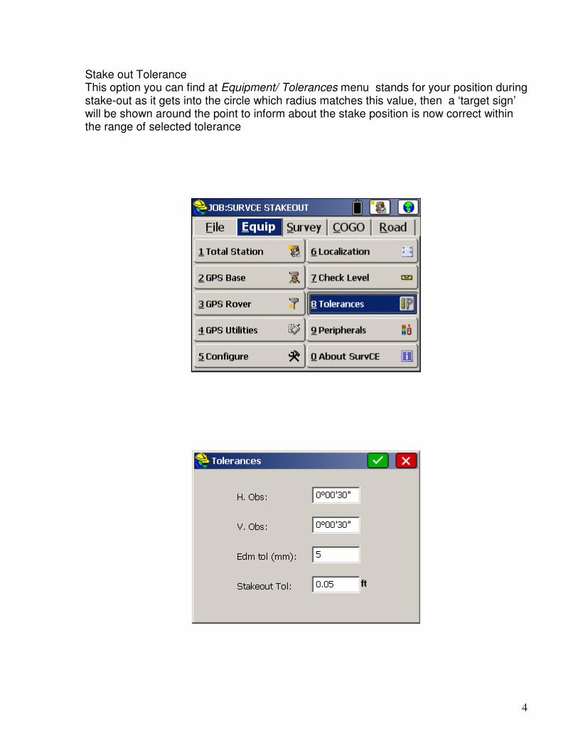
Stake offsets This command will stake out up to two user-defined horizontal offsets to a centerline at any station, as well as an unlimited number of offsets per station, if you are using a predefined Cutsheet Station and Offset List (loaded using the Settings button). It will also stake out the centerline itself. After selecting Horizontal and Vertical Alignment, the same way we did in Line/ Arc stake, a new screen will be shown where you can define a first offset with its x-fall (for the pavement) and a second one to define a curb (H and V offset). We can define different widths and x-falls on every side from Centerline
Elevation difference This routine will report a cut/fill in comparison to a design surface at any location within a project. For any surface where a centerline is defined (Road Design and Section, or Grid/Triangulation/Elevation with centerline defined), the routine will not only report, but optionally store cuts, fills and centerline position data into an alignment-style cutsheet file. With no centerline defined, the Road, Grid and Elevation methods will store cut and fill data into a point-style cutsheet file. Vertical offset can be applied to design surface and the Elevation Difference can also be indicated with a light bar.

15
There are five types of data that can be used to define the design surface.
1. Grid File: You may use a .GRD file that has been created using software packages including Carlson Civil or Carlson Survey.
2. Triangulation File: You may use a .TIN file created within SurvCE using the Triangulate & Contour command found in the Map screen under Tools, Surface. You can also use a .TIN or .FLT file that has been created Carlson Civil or Carlson Survey office products, in which case you must transfer this file to the collector via the File Transfer routine prior to running this command. Note that triangulation files can be imported from LandXML or DXF format using the command File, DTM Import, found in the Map screen.
3. Elevation: You may use known elevation that you specify in the Set Elevation field.
4. Road Design: This method requires a Template, Centerline and Profile file at a minimum, and can utilize superelevation and template transition files.
5. Section: This method requires a Cross Section file and a Centerline file.
Vertical Offset: This is used in conjunction with grid, triangulation, roading and section files. It allows the user to vertically offset the surface (as defined in the file) by the amount specified in the box. Use Centerline for Station-Offset: This allows the user to specify a horizontal alignment file (.cl file) for reporting station and offset of your current location to the reference alignment. With total stations this is reported whenever a shot is taken. Using GPS or robotic total stations, with tracking on, your current position is updated in real time as the rover or prism is moved. This option is available with Grid, Triangulation and Elevation types of surface models. (A centerline is required for Road Design and Section-type surfaces).

16
Stake Slopes The Stake Slope command calculates and stakes out the location of the “catch point” where fill slopes or cut slopes contact the original ground. The command will also set offset stakes to the catch point and will produce a report of the slope stake information. The slope stake is measured from a pivot point, which is user-entered, or starts at the centerline itself in “point-defined” alignments, or starts at the last template point before the cut or fills when templates are involved, or starts at the left and right end-points of sections when using section files Four Methods for Slope Staking
1. User-Defined: This is the most commonly used method of slope staking. Here, you simply enter the station, offset and elevation of the pivot point. Cut and fill slopes are entered in the field.
2. Point-Defined Alignments: This method is often used for staking the top of cut for a ditch, particularly a V-ditch. You can select the centerline by any of the three classic methods of centerline file, a picked polyline on the screen, or a sequence of points. This method is useful for slope staking existing flow lines, where you simply take two shots at either end, create an alignment by point number, then set the slope stakes at the user-entered slope ratio.
3. Design Files: This is the most “formal” way of slope staking, but typically only applies to uniform, simple road, drainage ditch or levee projects where the pivot offset positions do not vary from station to station. While all methods require that a centerline be selected, the design file method additionally requires, at a minimum, a template file and a profile
4. Section Files: Section files can be used to identify the pivot points left and right and minimize fieldwork. Catch point must not be included in the section definition and the last points on each side must be the pivot points of the slopes.

17
Stake Road Stake road is a powerful command you may use to stake every single detail from x-sections or templates with the option to see an x-section view in real-time with your own position approaching the design. It can also be used for slope staking as Stake Slope command and it’s the perfect tool to perform the precise roadbed work and fine grading When section files have been selected, a multi-layer section can be loaded and reference points can be selected for cut/fill from a different layer than the active one. There are 3 data inputs available: Design files (templates with or without super-elevation information), Section files and Alignments (or 3D polylines) that will be cut by vertical planes applied to the current station and converted into offsets to centerline.
The next screen is the heart of the command. From this screen, you can select a point from template, extend a surface of the template by following for example the same x-fall or even select a point in the surface at a particular offset. Then you press OK button and pass to the navigation screen. If Slope-Stake is selected, then you will enter in a ‘catch point’ routine for cut/ fill slopes staking where the pivot point and slope value can be user-defined

18
All these items can afterward be seen in a graphic plan or section view to help the user navigate and look for the requested points in sections.