Embed Size (px)
Citation preview

CCaarrrriieerr SSeennssoorrss IInnssttaallllaattiioonn GGuuiiddee
CARRIER CORPORATION ©2017 A member of the United Technologies Corporation family · Stock symbol UTX · Catalog No. 11-808-423-01 · 8/2/2017
Verify that you have the most current version of this document from www.hvacpartners.com or your local Carrier office.
Important changes are listed in Document revision history at the end of this document.
CARRIER CORPORATION ©2017. All rights reserved throughout the world. i-Vu is a registered trademark of Carrier Corporation. All other trademarks are the property of their respective owners.

Contents Introduction to Carrier sensors ................................................................................................................................... 1 ZS Sensors ................................................................................................................................................................... 3
Specifications ........................................................................................................................................................ 5 CO2 sensor installation ........................................................................................................................................ 6 Rnet Configuration ............................................................................................................................................... 6 Rnet wiring specifications ................................................................................................................................... 6 To address a ZS Sensor ....................................................................................................................................... 7 Power requirements ............................................................................................................................................. 8 To wire and mount a ZS Sensor ......................................................................................................................... 9 To communicate through the local access port............................................................................................ 10 Troubleshooting ................................................................................................................................................. 11
SPT Sensors ............................................................................................................................................................... 13 SPT Sensor specifications ................................................................................................................................ 14 Rnet Configuration ............................................................................................................................................ 15 To address an SPT Standard sensor ............................................................................................................... 15 Rnet wiring specifications ................................................................................................................................ 16 Mounting location .............................................................................................................................................. 16 To wire and mount the SPT sensor ................................................................................................................. 17 Using an SPT Sensor ......................................................................................................................................... 18 To change sensor properties ............................................................................................................................ 20 To communicate through the local access port............................................................................................ 20 Troubleshooting SPT Sensors .......................................................................................................................... 21
Alternate space temperature sensor ....................................................................................................................... 22 Sensor specifications ........................................................................................................................................ 23 Wiring specifications ......................................................................................................................................... 24 Mounting location .............................................................................................................................................. 24 To wire and mount the sensor ......................................................................................................................... 25 To change a T59 sensor's options ................................................................................................................... 26
Supply Air Temperature sensor ................................................................................................................................ 29 SAT sensor specifications ................................................................................................................................. 29 Wiring specifications ......................................................................................................................................... 30 Mounting location .............................................................................................................................................. 31 To wire and mount the SAT sensor ................................................................................................................. 31
Duct Air Temperature sensor .................................................................................................................................... 32 DAT sensor specifications ................................................................................................................................ 32 Wiring specifications ......................................................................................................................................... 33 Mounting location .............................................................................................................................................. 33 To wire and mount the DAT sensor ................................................................................................................. 34
Outdoor Air Temperature sensor .............................................................................................................................. 35 OAT sensor specifications ................................................................................................................................ 35 Wiring specifications ......................................................................................................................................... 36 Mounting location .............................................................................................................................................. 36 To wire and mount the OAT sensor ................................................................................................................. 37
Primary Air Temperature sensor .............................................................................................................................. 38 PAT sensor specifications................................................................................................................................. 38 Wiring specifications ......................................................................................................................................... 39 Mounting location .............................................................................................................................................. 39 To wire and mount the PAT sensor ................................................................................................................. 40
CO2 sensor ................................................................................................................................................................. 41 CO2 sensor specifications ................................................................................................................................ 42

Contents
Wiring specifications ......................................................................................................................................... 42 Mounting location .............................................................................................................................................. 43 To wire and wall-mount the CO2 sensor ........................................................................................................ 43 To wire and duct-mount the sensor ................................................................................................................ 44
CO2/Temperature sensor ......................................................................................................................................... 46 CO2/Temperature sensor specifications ....................................................................................................... 47 Wiring specifications ......................................................................................................................................... 48 Mounting location .............................................................................................................................................. 48 To wire and mount the CO2/Temperature sensor ....................................................................................... 48
Relative Humidity sensors ........................................................................................................................................ 50 Sensor specifications ........................................................................................................................................ 51 Wiring specifications ......................................................................................................................................... 52 Mounting location .............................................................................................................................................. 52 To wire and mount the Space RH sensors ..................................................................................................... 53 Typical power wiring diagrams for Space RH sensors ................................................................................. 55 To wire and mount the Duct RH sensor ......................................................................................................... 56 To wire and mount the Outdoor RH sensor ................................................................................................... 57 Typical power wiring diagrams for Duct RH and Outdoor RH sensors ...................................................... 58 Calibrating and troubleshooting relative humidity sensors ........................................................................ 59
Enthalpy switch/receiver and Enthalpy sensor ....................................................................................................... 61 Enthalpy switch/sensor specifications ........................................................................................................... 62 Wiring specifications ......................................................................................................................................... 62 Mounting location .............................................................................................................................................. 62 To wire and mount the switch/sensor ............................................................................................................ 63
Appendix: i-Vu® Control System Wiring Specifications and Recommended Vendors ....................................... 65 Document revision history ........................................................................................................................................ 66 Index ........................................................................................................................................................................... 67

Carrier Sensors Carrier Proprietary and Confidential CARRIER CORPORATION ©2017 Installation Guide All rights reserved 1
The following Carrier sensors can be used with the specified Open controllers. For information on Carrier PIC controllers, please see the controller's Installation Guide.
Controller
Sensor
Part number VV
T Zo
ne
VVT
Bypa
ss
RTU
Open
Chill
erVu
™
UC O
pen
UC O
pen
XP
MPC
Ope
n XP
AppC
ontro
ller
VAV
Zone
UPC
Open
Space temperature sensor (page 13) ZS* ZSPL* ZSP* ZSPF*
• • •
• • •
• • • •
• • • •
• • • •
• • • •
• • • •
• • •
SPS SPPL SPP SPPF
• • •
• • •
• • • •
• • • •
• • • •
• • • •
• • • •
• • •
• • • •
Alternate space temperature sensor (page 22) 33ZCT55SPT 33ZCT56SPT 33ZCT59SPT
• • • •
• • •
• • •
• •
Supply Air Temperature sensor (page 29) 33ZCSENSAT • • • • • • •
Duct Air Temperature sensor (page 32) 33ZCSENDAT • • • • • •
Outdoor Air Temperature sensor (page 35) 33ZCSENOAT • • • •
Primary Air Temperature sensor (page 38) 33ZCSENPAT • • •
CO2 sensor (page 41) 33ZCSPTCO2-01,
33ZCSPTCO2LCD-01
• • • • • •
CO2/Temperature sensor (page 46) ** 33ZCT55CO2 33ZCT56CO2
• • • •
• • • • •
Wall Relative Humidity sensor (page 50) 33ZCSENSRH-02 • • • • • •
Duct Relative Humidity sensor (page 50) 33ZCSENDRH-02 • • • •
Outdoor Relative Humidity sensor (page 50) 33ZCSENORH-02 • • • •
Enthalpy switch/receiver (page 61) Enthalpy sensor (page 61)
33CSENTHSW 3CSENTSEN
• •
• •
• • •
•
* ZS Sensors are thermistor-based temperature sensors that may optionally sense humidity, CO2, or VOC.
Introduction to Carrier sensors

Introduction to Carrier sensors
Carrier Sensors Carrier Proprietary and Confidential CARRIER CORPORATION ©2017 Installation Guide All rights reserved 2
WARNING Disconnect electrical power to the controller or sensor before wiring it. Failure to follow this warning could cause electrical shock, personal injury, or damage to the device.
CAUTION Do not run sensor or relay wires in the same conduit or raceway with Class 1 AC or DC service wiring.
• Do not abrade, cut, or nick the outer jacket of the cable.
• Do not pull or draw cable with a force that may harm the physical or electrical properties.
• Avoid splices in any control wiring.

ZS Sensors
Carrier Sensors Carrier Proprietary and Confidential CARRIER CORPORATION ©2017 Installation Guide All rights reserved 3
ZS Sensors are thermistor-based temperature sensors that may optionally sense humidity, CO2, or VOC. ZS Sensors are wired to the Rnet on i-Vu® Open controllers:
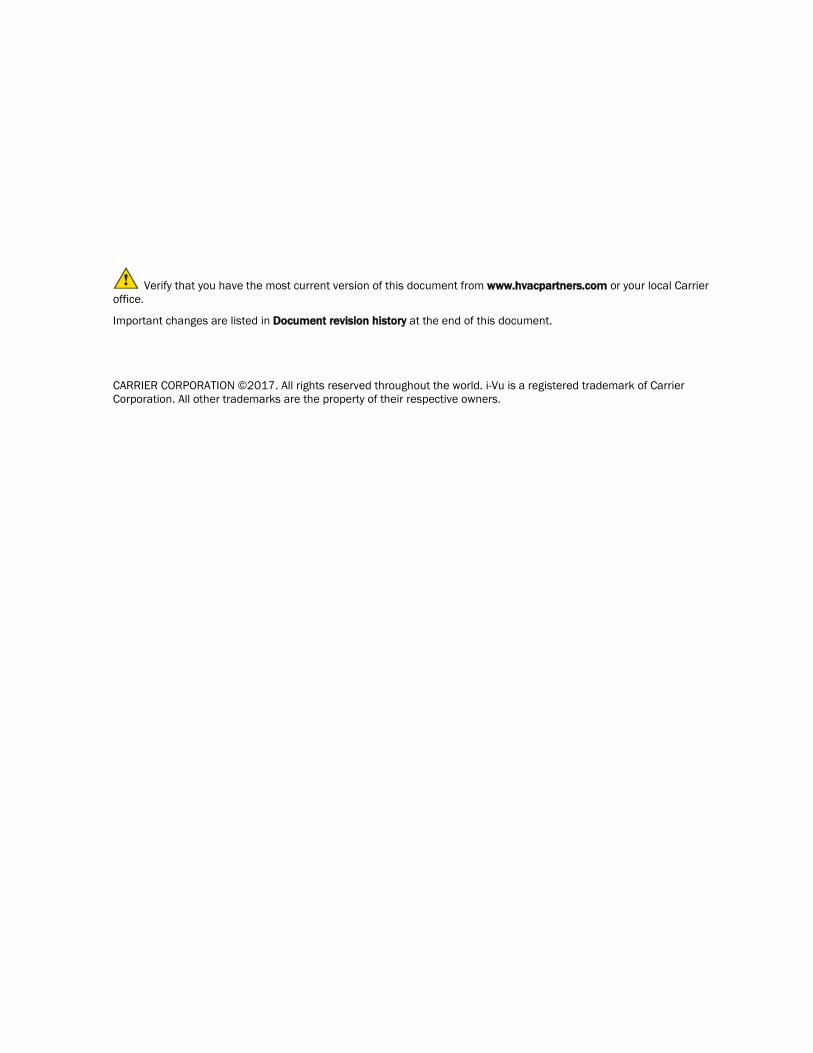
The following table shows the 4 ZS Sensor models and their features.
Part # with Carrier logo
Part # wihout logo
Sensor Features
ZS-CAR
ZS-C-CAR
ZS-H-CAR
ZS-V-CAR
ZS-HC-CAR
ZS-HV-CAR
ZS-BNK
ZS-C-BNK
ZS-H-BNK
ZS-V-BNK
ZS-HC-BNK
ZS-HV-BNK
ZS Standard
• Local access port • No user control
ZSPL-CAR
ZSPL-C-CAR
ZSPL-H-CAR
ZSPL-V-CAR
ZSPL-HC-CAR
ZSPL-HV-CAR
ZSPL-BNK
ZSPL-C-BNK
ZSPL-H-BNK
ZSPL-V-BNK
ZSPL-HC-BNK
ZSPL-HV-BNK
ZS Plus
• Slide potentiometer to make the zone warmer or cooler
• button to override the schedule and put the zone in an occupied state, or force the zone to an unoccupied state
• Green LED to indicate occupied state • Local access port
ZS Sensors
ZS Sensors
Carrier Sensors Carrier Proprietary and Confidential CARRIER CORPORATION ©2017 Installation Guide All rights reserved 4
Part # with Carrier logo
Part # wihout logo
Sensor Features
ZSP-CAR
ZSP-C-CAR
ZSP-H-CAR
ZSP-V-CAR
ZSP-HC-CAR
ZSP-HV-CAR
ZSP-BNK
ZSP-C-BNK
ZSP-H-BNK
ZSP-V-BNK
ZSP-HC-BNK
ZSP-HV-BNK
ZS Pro
• LCD display
• button to override the schedule and put the zone in an occupied state, or force the zone to an unoccupied state
• and buttons to change any editable property, such as the setpoint temperature
• button to cycle through information defined in the control program
• Green LED to indicate occupied state • Local access port
ZSPF-CAR
ZSPF-C-CAR
ZSPF-H-CAR
ZSPF-V-CAR
ZSPF-HC-CAR
ZSPF-HV-CAR
ZSPF-BNK
ZSPF-C-BNK
ZSPF-H-BNK
ZSPF-V-BNK
ZSPF-HC-BNK
ZSPF-HV-BNK
ZS Pro-F
All of the ZS Pro's features plus:
• button to turn on heating, cooling, or fan only, or set to auto control.
• button to adjust fan speed • F/C button to set temperatures to
Fahrenheit or Celsius
To configure the control program for the desired user interaction with the sensor, see the ZS Sensor Application Guide.
For basic user instructions, see the ZS Sensor User Guide.

ZS Sensors
Carrier Sensors Carrier Proprietary and Confidential CARRIER CORPORATION ©2017 Installation Guide All rights reserved 5
Specifications
Sensing element accuracy
Temperature Temperature only: 32° to 122°F (0° to 50°C): ±0.36°F (0.2°C)
Temperature if humidity is included: 50° to 104°F (10° to 40°C): ±0.54°F (0.3°C)
Humidity 10% to 90%: ±1.8% typical. Less than 0.5% drift per year.
CO2 400 to 1250 PPM: ±30 PPM or 3% of reading, whichever is greater 1250 to 2000 PPM: ±5% of reading plus 30 PPM
See CO2 sensor installation (page 6).
VOC 0 to 2,000 CO2 PPM Equivalent: ±100PPM
Power requirements Temperature only ZS Standard or ZS Plus: ZS Pro or Pro-F:
12 Vdc @ 6 mA 12 Vdc @ 7 mA
Temperature with humidity ZS Standard or ZS Plus: ZS Pro or Pro-F:
12 Vdc @ 7 mA 12 Vdc @ 8 mA
Temperature with humidity and VOC - All models
12 Vdc @ 60 mA
Temperature with humidity and CO2 - All models
12 Vdc @ 15 mA (idle) to 190 mA (CO2 measurement cycle)
Temperature and CO2 - All models
12 Vdc @ 14 mA (idle) to 189 mA (CO2 measurement cycle)
Power supply The 4-conductor Rnet cable from a controller supplies +12 Vdc @ 210 mA. For additional power, use an external power supply. Use the above power requirements to calculate the size of the external power supply. The controller and the external power supply must share a common ground.
Communication 115 kbps
Local access port
For local access to start up and troubleshoot the system
Environmental operating range
32 to 122°F (0 to 50°C), 10 to 90% relative humidity, non-condensing
Mounting Standard 4x2-in. electrical box using the 6-32 x 1/2" mounting screws provided
Overall dimensions Temperature sensor or temperature with humidity sensor
Width: Height: Depth:
3 in. (7.62 cm) 4-13/16 in. (12.22 cm) 13/16 in. (2.01 cm)
Sensor with CO2 or VOC Width: Height: Depth:
2-7/8 in. (7.3 cm) 4-13/16 in. (12.22 cm) 1-1/4 in. (3.18 cm)
Listed by FCC Part 15-Subpart B-Class A, CE

ZS Sensors
Carrier Sensors Carrier Proprietary and Confidential CARRIER CORPORATION ©2017 Installation Guide All rights reserved 6
CO2 sensor installation
IMPORTANT Do not install ZS CO2 sensors in continuous occupancy applications. For a ZS CO2 sensor to maintain accuracy, it must be installed only in a zone that is unoccupied for at least 4 hours a day with enough air movement during the unoccupied period to return CO2 to background levels.
A ZS sensor with CO2 uses Automatic Background Calibration which waits for the lowest value in a 24-hour period that deviates no more than 40PPM for at least 15 minutes, and assigns that value to the 400PPM baseline. This daily Automatic Background Calibration may take up to 21 days to fully calibrate the sensor.
NOTE Dropping a sensor can upset the calibration, and it may require 21 days to return to our stated accuracy.
Rnet Configuration
An Rnet can consist of the following devices wired in a daisy-chain or star configuration: • Up to 15 ZS Sensors
NOTE You cannot have more than 5 sensors per control program • Up to 5 ZS sensors and 1 Equipment Touch device
NOTE You cannot have SPT sensors and ZS sensors on the same Rnet.
Rnet wiring specifications
NOTE Use the specified type of wire and cable for maximum signal integrity.
Description 4 conductor, shielded or unshielded, CMP, plenum rated cable
Conductor 22 AWG (7x0096) bare copper
Maximum length 500 feet (152 meters)
Insulation Low-smoke PVC (or equivalent)
Color Code Black, white, green, red
Shielding If shielded, Aluminum/Mylar shield (100% coverage) with TC drain wire
UL temperature rating 32–167°F (0–75°C)
Voltage 300 Vac, power limited
Listing UL: NEC CL2P, or better

ZS Sensors
Carrier Sensors Carrier Proprietary and Confidential CARRIER CORPORATION ©2017 Installation Guide All rights reserved 7
To address a ZS Sensor
Each ZS Sensor on an Rnet must have a unique address, but addresses do not have to be sequential.
Use the DIP switches on the back of the ZS Sensor to set an address from 0 to 14. (1 is factory default.) Each DIP switch has the value shown in the figure below. Turn on as many DIP switches as you need so that their total value equals the address.
DIPSwitchvalue
1 ON
248
12
34
EXAMPLE DIP switches 1 and 4 above are on. Their values (1 + 8) total 9, so the sensor's address is 9.

ZS Sensors
Carrier Sensors Carrier Proprietary and Confidential CARRIER CORPORATION ©2017 Installation Guide All rights reserved 8
Power requirements
See Specifications (page 5) for power requirements and power supply information.
CAUTION Do not share power between controller's power and external 12 Vdc unless both devices are half wave.

ZS Sensors
Carrier Sensors Carrier Proprietary and Confidential CARRIER CORPORATION ©2017 Installation Guide All rights reserved 9
To wire and mount a ZS Sensor
PREREQUISITE The Rnet cable is wired to the controller. The shield wire and the ground wire should be inserted into the controller's GND terminal.
1 Turn off the controller's power.
2 Pull the backplate off the ZS Sensor. You may need to turn the setscrews in the bottom of the sensor clockwise until you can remove the backplate.
3 Pull the Rnet communication cable through the slit in the insulated backing material.
3.30 in.(8.38 cm)
4 Use 2 screws to mount the backplate to the wall or outlet box.
Partially cut, then bend and pull off the outer jacket of the Rnet cable(s). Do not nick the inner insulation.
Inner insulation
Outer jacket
Foil shield.25 in.(.6 cm)
Shield wire
5 Strip about .25 inch (.6 cm) of the inner insulation from each wire.
6 If wiring 1 cable to the ZS Sensor, cut the shield wire off at the outer jacket, then wrap the cable with tape at the outer jacket to cover the end of the shield wire.
If wiring 2 cables in a daisy-chain configuration, twist together the shield wires, then wrap the shield wires with tape.
7 Insert the other 4 wires into the ZS Sensor's screw terminal connector. If wiring 2 cables, insert like-colored wires into each terminal.
Carrier recommends that you use the following Rnet wiring scheme:
Connect this wire...
Red
Black
White
Green
To this terminal...
+12V
Rnet-
Rnet+
Gnd
ZS Sensors
Carrier Sensors Carrier Proprietary and Confidential CARRIER CORPORATION ©2017 Installation Guide All rights reserved 10
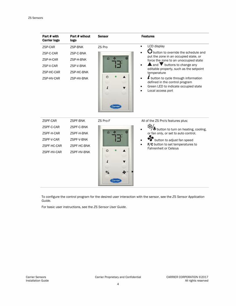
CAUTION Allow no more than 0.06 inch (1.5 mm) bare communication wire to protrude. If bare communication wire contacts the cable's foil shield, shield wire, or a metal surface other than the terminal block, the device may not communicate correctly.
8 Attach the sensor's cover and circuit board to the mounted backplate, inserting the top first.
9 Turn the setscrews one full turn counterclockwise so that the cover cannot be removed.
10 Turn on the controller's power.
NOTE Use the same polarity throughout the Rnet.
To communicate through the local access port
You can connect to the Local Access port of the ZS Sensor to perform test and balance or to make changes to any device on the network.
PREREQUISITES
• A computer with a USB port
• A USB Link (Part #USB-L)
CAUTION If multiple controllers share power but polarity was not maintained when they were wired, the difference between the controller's ground and the computer's AC power ground could damage the USB Link and the controller. If you are not sure of the wiring polarity, use a USB isolator between the computer and the USB Link. Purchase a USB isolator online from a third-party manufacturer.
Connect the USB Link to the computer and to the ZS Sensor's local access port.
USB Link
Connect toLocal Access port
12 ft
Connect toUSB port
7 3/4 in.
NOTE If using a USB isolator, plug the isolator into your computer's USB port, and then plug the USB Link cable into the isolator.

ZS Sensors
Carrier Sensors Carrier Proprietary and Confidential CARRIER CORPORATION ©2017 Installation Guide All rights reserved 11
Troubleshooting
ZS Pro or ZS Pro-F
If display shows... Then...
Incorrect or missing values
Check for errors in the i-Vu® application and Snap.
On the control program's Properties page, select the Rnet Points tab. Verify that values coming in from the sensors and those going out to the sensors are expected values.
In the i-Vu® application, double-click the Sensor Binder and ASVI microblocks to check for problems in the Status and/or Error columns.
If the Error column shows Resource Allocation, try formatting the sensor. If the error is not corrected by formatting, the control program engineer should reduce the number of items that the sensor is trying to display.
Nothing The sensor has no power.
The sensor is not communicating with the network. Check: • Software/addressing setup • Wiring connections • Controller operating status
Characters that seem out of place
The sensor may have a memory problem. Try formatting the sensor.

ZS Sensors
Carrier Sensors Carrier Proprietary and Confidential CARRIER CORPORATION ©2017 Installation Guide All rights reserved 12
To format a ZS Sensor Formatting a sensor clears its flash memory. Do either of the following to format a sensor:
• Download the controller that the sensor is connected to.
• Do the following:
a) Remove the wiring connector from the sensor.
b) Note the current position of the DIP switches.
c) Set all DIP switches to the ON position.
d) Reattach the wiring connector to format.
e) After approximately 3 seconds, remove the wiring connector.
f) Set the DIP switches back to their original position.
g) Reattach the wiring connector.
NOTE If you move a sensor from one controller to another controller that has a different control program, format the sensor.

SPT Sensors
Carrier Sensors Carrier Proprietary and Confidential CARRIER CORPORATION ©2017 Installation Guide All rights reserved 13
Part #SPS, SPPL, SPP, SPPF
An SPT sensor is a thermistor-based, wall-mounted temperature sensor that monitors zone temperature. An SPT sensor is wired to a controller's Rnet port.
Carrier offers the following SPT sensors:
Sensor Features
SPT Standard Part #SPS
• Local access port • No operator control
SPT Plus Part #SPPL
• Slide potentiometer to adjust setpoint • MANUAL ON button to override schedule • LED to show occupied status • Local access port
SPT Sensors

SPT Sensors
Carrier Sensors Carrier Proprietary and Confidential CARRIER CORPORATION ©2017 Installation Guide All rights reserved 14
Sensor Features
SPT Pro Part #SPP
• LCD display • MANUAL ON button to override schedule • WARMER and COOLER buttons to adjust
setpoint • INFO button to cycle through zone and outside
air temperatures, setpoints, and local override time
• Local access port
SPT Pro Plus Part #SPPF
• LCD display • MANUAL ON button to override schedule • WARMER and COOLER buttons to adjust
setpoint • INFO button to cycle through zone and outside
air temperatures, setpoints, and local override time
• FAN SPEED button to adjust fan speed • Local access port
SPT Sensor specifications
Sensor Thermistor. Accuracy ±0.45°F (0.25°C). Less than ±0.18°F (0.1°C) drift over a 10 year period.
Sensor range 50°F to 95°F (10°C to 35°C)
Power Supplied by the 4-conductor cable (+12 Vdc @ 210 mA) from the controller.
Communication 115 kbps
Local access port For local access to start up and troubleshoot system

SPT Sensors
Carrier Sensors Carrier Proprietary and Confidential CARRIER CORPORATION ©2017 Installation Guide All rights reserved 15
Environmental operating range
32–122°F (0–50°C), 10–90% relative humidity, non-condensing
Mounting Standard 4x2-in. electrical box using provided 6-32 by 1/2 in. mounting screws.
Overall dimensions: Width: Height: Depth:
2-3/4 in. (6.9 cm) 4-3/4 in. (12.1 cm) 5/8 in. (1.6 cm)
Rnet Configuration
You wire SPT sensors to a controller's Rnet port. An Rnet can consist of any of the following combinations of devices wired in a daisy-chain or hybrid configuration: • 1 SPT Plus, SPT Pro, or SPT Pro Plus • 1–4 SPT Standards • 1–4 SPT Standards, and 1 SPT Plus SPT Pro, or SPT Pro Plus • Any of the above combinations, plus up to 2 BACview®6's but no more than 6 devices total
NOTE You must set addresses only on the following Rnet devices: • SPT Standard sensors if you have more than one on the Rnet. See To address an SPT Standard sensor (page
15). • BACview®6's if you have two on the Rnet. See the BACview® Installation and User Guide.
To address an SPT Standard sensor
If the Rnet has multiple SPT Standard sensors, the first sensor retains its default address of 1. You must give each additional SPT Standard a unique address on the Rnet. To set the address:
1 Pull the back plate off the sensor, pulling from the bottom first.
2 Remove the two hexagonal screws that attach the circuit board to the cover plate.
3 Remove the cover plate.
4 On the circuit board, set the address jumper to 2, 3, or 4.
5 Attach the circuit board to the cover plate with the hexagonal screws.

SPT Sensors
Carrier Sensors Carrier Proprietary and Confidential CARRIER CORPORATION ©2017 Installation Guide All rights reserved 16
Rnet wiring specifications
NOTE Use the specified type of wire and cable for maximum signal integrity.
Description 4 conductor, unshielded, CMP, plenum rated cable
Conductor 18 AWG
Maximum length 500 feet (152 meters)
Recommended coloring Jacket: White Wiring: Black, white, green, red
UL temperature rating 32–167°F (0–75°C)
Voltage 300 Vac, power limited
Listing UL: NEC CL2P, or better
Mounting location
Mount the sensor: • In an area representing the average temperature in the space • On an interior wall • Approximately 5 feet (1.5 meters) from the floor, or as required by local code • At least 4 feet (1.2 meters) from any corner • At least 2 feet (.6 meter) from an open doorway
Do not mount the sensor: • In drafty locations such as near air conditioning or heating ducts, or near open windows • Over heat sources such as baseboard heaters, radiators, directly above wall-mounted lighting dimmers, or in
direct sunlight
NOTE The sensor mounting plate accommodates the NEMA standard 2x4 in. standard single gang electrical box. However, the sensor can be mounted directly on the wall surface if local codes permit.

SPT Sensors
Carrier Sensors Carrier Proprietary and Confidential CARRIER CORPORATION ©2017 Installation Guide All rights reserved 17
To wire and mount the SPT sensor
NOTE The sensor mounting plate accommodates the NEMA standard 2x4 in. standard single gang electrical box. However, the sensor can be mounted directly on the wall surface if local codes permit.
1 Remove the mounting plate from the SPT sensor. You may need to turn the setscrew in the bottom of the sensor clockwise until you can remove the mounting plate.
2 Pull the Rnet communication cable through the wire guide in the mounting plate.
3.30 in.(8.38 cm)
3 Use the 2 mounting screws provided to attach the mounting plate to the wall or electrical box.
4 Partially cut, then bend and pull off the outer jacket of the Rnet cable(s). Do not nick the inner insulation. Strip about .25 inch (.6 cm) of the inner insulation from each wire.
Outer Jacket
Inner insulation.25 in.(.6 cm)
5 Insert the other 4 wires into the sensor's screw terminal connector. If wiring 2 cables, insert like-colored wires into each terminal.
Carrier recommends that you use the following Rnet wiring scheme:
Connect this wire...
Red
Black
White
Green
To this terminal...
+12V
Rnet-
Rnet+
Gnd
CAUTION Allow no more than .06 inch (1.5 mm) bare communication wire to protrude. If bare communication wire contacts a metal surface other than the terminal block, the sensor may not communicate correctly.

SPT Sensors
Carrier Sensors Carrier Proprietary and Confidential CARRIER CORPORATION ©2017 Installation Guide All rights reserved 18
6 Attach the sensor's cover and circuit board to the mounting plate, inserting the top first.
7 Turn the setscrew one full turn counterclockwise to secure the cover to the mounting plate.
8 Wire the sensor to the Open controller. See the controller's Installation and Startup Guide for details.
Using an SPT Sensor
All SPT Sensors Feature Usage
Local Access port See To communicate through the Local Access port (page 10).
SPT Plus Feature Usage
Slide potentiometer Move the potentiometer to raise or lower the zone's setpoint. The maximum you can adjust the setpoint is defined in the Max Adjust field*.
MANUAL ON button Press this button one time to override the schedule and set the zone to occupied for the amount of time defined in the Each pulse field*. Press the button again to incrementally increase the time. For example, if the Each pulse field is set at five minutes, press the button once for an occupancy of five minutes, twice for ten minutes, and so on. The maximum length of time you can override the schedule is defined in the Max Accum field*.
To cancel the override, hold down the MANUAL ON button until the OCCUPIED LED turns off.
OCCUPIED LED The LED lights when the zone is occupied from a regular schedule or a manual override.

SPT Sensors
Carrier Sensors Carrier Proprietary and Confidential CARRIER CORPORATION ©2017 Installation Guide All rights reserved 19
SPT Pro Feature Usage
Display The display shows occupancy, zone temperature, and an alarm bell icon. Celsius values are to the nearest 0.5 degree; Fahrenheit values are to the nearest full degree.
The display shows Occupied when the zone is occupied from a regular schedule or from a manual override.
MANUAL ON button Press one time to override the schedule and set the zone to occupied for the amount of time defined in the Each pulse field*. Press button again to incrementally increase the time. For example, if the Each pulse field is set at five minutes, press the button once for an occupancy of five minutes, twice for ten minutes, and so on. The maximum length of time you can override the schedule is defined in the Max Accum field*.
The display shows the duration of the override in minutes. If the override time exceeds 199 minutes, the display shows the time in hours.
To cancel the override, hold the button down until 0 displays. Wait five seconds for the display to show the current zone temperature again.
WARMER and COOLER buttons
To raise or lower the zone's setpoint:
1 Press either button to display the current average setpoint (the average between the heating and cooling setpoints).
2 Press either button again to raise or lower the setpoint. You can adjust the setpoint by no more than the amount defined in the Max Adjust field*.
NOTE Pressing either button overrides an unoccupied schedule and sets the zone to occupied for the amount of time defined in the Each pulse field*.
INFO button Press to cycle through the: • zone temperature • outside air temperature, if enabled in the control program • override time, in minutes • heating setpoint • cooling setpoint
SPT Pro Plus The SPT Pro Plus has all the features of the SPT Pro plus the additional functionality described below.
Feature Usage
MANUAL ON button The Timed Local Override section of the microblock dialog box determines if pressing the MANUAL ON button sets the zone to occupied for a set amount of time in the same manner as the SPT Pro or sets the zone to continuously occupied.
INFO button This button cycles through the same information as the SPT Pro.

SPT Sensors
Carrier Sensors Carrier Proprietary and Confidential CARRIER CORPORATION ©2017 Installation Guide All rights reserved 20
To change sensor properties
You can use the i-Vu® application or Field Assistant, if included with your system, to change sensor properties such as the override time or maximum setpoint adjustment. Go to Properties page > I/O Points tab > and click on your applicable sensor point, i.e. Space Temp, SPT Temp Sensor, Zone Temp Sensor > Details tab of microblock popup.
Field Assistant runs on a laptop that you connect to an SPT sensor's Local Access port.
To communicate through the local access port
You can connect to the Local Access port of the ZS Sensor to perform test and balance or to make changes to any device on the network.
PREREQUISITES
• A computer with a USB port
• A USB Link (Part #USB-L)
CAUTION If multiple controllers share power but polarity was not maintained when they were wired, the difference between the controller's ground and the computer's AC power ground could damage the USB Link and the controller. If you are not sure of the wiring polarity, use a USB isolator between the computer and the USB Link. Purchase a USB isolator online from a third-party manufacturer.
Connect the USB Link to the computer and to the ZS Sensor's local access port.
USB Link
Connect toLocal Access port
12 ft
Connect toUSB port
7 3/4 in.
NOTE If using a USB isolator, plug the isolator into your computer's USB port, and then plug the USB Link cable into the isolator.

SPT Sensors
Carrier Sensors Carrier Proprietary and Confidential CARRIER CORPORATION ©2017 Installation Guide All rights reserved 21
Troubleshooting SPT Sensors
Use the following tables to troubleshoot an SPT sensor.
SPT Standard or SPT Plus If LED on back of circuit board... Then sensor...
Is not lit Has no power
Blinks 1 time per second Has power, but is not communicating
Blinks 2.5 times per second Is correctly wired and communicating
SPT Pro or SPT Pro Plus If display shows... Then sensor...
Nothing Has no power
All display elements Has power, but is not communicating
Only the temperature and current status Is correctly wired and communicating
NOTE If OF is displayed, cycle the power on the controller.

Alternate space temperature sensor
Carrier Sensors Carrier Proprietary and Confidential CARRIER CORPORATION ©2017 Installation Guide All rights reserved 22
Part #33ZCT55SPT, 33ZCT56SPT, 33ZCT59SPT
The following wall-mounted space temperature sensors can be used instead of an SPT sensor to monitor zone temperature.
Sensor Features
T-55 Part #33ZCT55SPT
• Timed override button
T-56 Part #33ZCT56SPT
• Timed override button • Setpoint adjustment
Alternate space temperature sensor

Alternate space temperature sensor
Carrier Sensors Carrier Proprietary and Confidential CARRIER CORPORATION ©2017 Installation Guide All rights reserved 23
Sensor Features
T-59 Part #33ZCT59SPT
• Timed override button • Setpoint adjustment • LCD display
NOTE The T-59 sensor requires a dedicated 24 Vac, 3 Va transformer to power the sensor.
Sensor specifications
Operating range T55 and T56: 32° to 120°F (0° to 49°C) with a nominal resistance of 10,000 ohms at 77°F (25°C). See table below.
T59: 40° to 104°F (5° to 40°C) with a nominal resistance of 10,000 ohms at 77°F (25°C). See table below.
Sensor tolerance T55 and T56: ±0.2°C from 0 to 70°C
T59: ±1°F from 40 to 104°C (±1°C from 4 to 40°C)
Humidity 0 to 95%, non-condensing
Power 24 Vac, 3 Va
Dimensions: Width: Height: Depth:
2 3/4 in. (6.98 cm) 4 1/2 in. (11.46 cm) 1 1/5 in. (2.92 cm)

Alternate space temperature sensor
Carrier Sensors Carrier Proprietary and Confidential CARRIER CORPORATION ©2017 Installation Guide All rights reserved 24
Thermistor Resistance vs. Temperature Values for Space Temperature Sensor
10K Type II (CP/MCI) Temp (F) Temp (C) Resistance (Ohms)
-40 -31 -22 -13
-4 5
14 23 32 41 50 59 68 77 86 95
104 113 122 131 140 149 158
-40 -35 -30 -25 -20 -15 -10
-5 0 5
10 15 20 25 30 35 40 45 50 55 60 65 70
335,651 242,195 176,683 130,243
96,974 72,895 55,298 42,315 32,651 25,395 19.903 15,714 12,494 10,000
8,056 6,530 5,325 4,367 3,601 2,985 2,487 2,082 1,752
Wiring specifications
Cable from sensor to controller: If <100 ft (30.5 meters) 22 AWG, unshielded If >100 ft (30.5 meters) 22 AWG, shielded
Maximum length: 500 feet (152 meters)
Mounting location
Mount the sensor: • In an area representing the average temperature in the space • On an interior wall • Approximately 5 feet (1.5 meters) from the floor, or as required by local code • At least 4 feet (1.2 meters) from any corner • At least 2 feet (.6 meter) from an open doorway
Do not mount the sensor: • In drafty locations such as near air conditioning or heating ducts, or near open windows • Over heat sources such as baseboard heaters, radiators, directly above wall-mounted lighting dimmers, or in
direct sunlight
NOTE The sensor mounting plate accommodates the NEMA standard 2x4 in. standard single gang electrical box. However, the sensor can be mounted directly on the wall surface if local codes permit.

Alternate space temperature sensor
Carrier Sensors Carrier Proprietary and Confidential CARRIER CORPORATION ©2017 Installation Guide All rights reserved 25
To wire and mount the sensor
1 Turn the 2 setscrews at the bottom of the sensor clockwise to release the sensor's cover from the mounting plate.
2 Lift the cover from the bottom, and then release it from the top fasteners.
3 Feed the wires from the electrical box through the opening in the center of the sensor mounting plate.
4 Use the 2 mounting screws provided to attach the mounting plate to the electrical box.
5 Strip the outer jacket from the cable for at least 3 inches (7.62 cm). Strip .25 inch (.6 cm) of insulation from each wire. Cut the shield and drain wire from the cable.
6 Use the appropriate diagram below to connect the wiring to the sensor's terminals.
7 Reattach the sensor's cover to the mounting plate, inserting the top first.
8 Turn the two Allen screws counterclockwise to secure the cover to the mounting plate.
9 Wire the sensor to the Open controller. See the controller's Installation and Startup Guide for details.
NOTE Clean sensor with damp cloth only. Do not use solvents.
T-55 sensor T-56 sensor T-59 sensor
Red
Blk (Gnd)
White
Jumperterminals
SEN SETSEN
Blk (Gnd) SensorwiringRed
Sensorwiring
Blu
BlkBrn
Sensorwiring
PWR+COM-OPB
Alternate space temperature sensor
Carrier Sensors Carrier Proprietary and Confidential CARRIER CORPORATION ©2017 Installation Guide All rights reserved 26
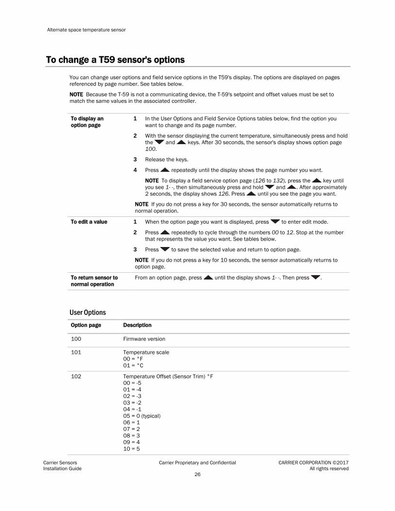
To change a T59 sensor's options
You can change user options and field service options in the T59's display. The options are displayed on pages referenced by page number. See tables below.
NOTE Because the T-59 is not a communicating device, the T-59's setpoint and offset values must be set to match the same values in the associated controller.
To display an option page
1 In the User Options and Field Service Options tables below, find the option you want to change and its page number.
2 With the sensor displaying the current temperature, simultaneously press and hold the and keys. After 30 seconds, the sensor's display shows option page 100.
3 Release the keys.
4 Press repeatedly until the display shows the page number you want.
NOTE To display a field service option page (126 to 132), press the key until you see 1- -, then simultaneously press and hold and . After approximately 2 seconds, the display shows 126. Press until you see the page you want.
NOTE If you do not press a key for 30 seconds, the sensor automatically returns to normal operation.
To edit a value 1 When the option page you want is displayed, press to enter edit mode.
2 Press repeatedly to cycle through the numbers 00 to 12. Stop at the number that represents the value you want. See tables below.
3 Press to save the selected value and return to option page.
NOTE If you do not press a key for 10 seconds, the sensor automatically returns to option page.
To return sensor to normal operation
From an option page, press until the display shows 1- -. Then press .
User Options Option page Description
100 Firmware version
101 Temperature scale 00 = °F 01 = °C
102 Temperature Offset (Sensor Trim) °F 00 = -5 01 = -4 02 = -3 03 = -2 04 = -1 05 = 0 (typical) 06 = 1 07 = 2 08 = 3 09 = 4 10 = 5

Alternate space temperature sensor
Carrier Sensors Carrier Proprietary and Confidential CARRIER CORPORATION ©2017 Installation Guide All rights reserved 27
Option page Description
103 Normal Setpoint Display 00 to 09 = Do Not Use Offset Setpoint Display 10 = -02 to 02°F (-02 to 02°C) 11 = -03 to 03°F (-03 to 03°C) 12 = -05 to 05°F (-05 to 05°C)
104 Keep at 00
105 Setpoint Lockout 00 = Disable Lockout 01 = Enable Lockout
106 Keep at 00
107 Keep at 00
108 Display Mode 00 = Normal 01 = Setpoint Only
109 Keep at 00
Field Service Options Page Description
126 Setpoint mode 00 = Use option page 103 setting 01 = Display single offset setpoint 02 = Display Heat/Cool setpoints 03 = Display Heat/Cool setpoints w/Occupied (Occupied icon is shown in setpoint display mode.)
127 Setpoint feedback 00 = Disable feedback 01 = Enable Occupied/unoccupied feedback 02 = Enable Heat/Cool feedback
128 Maximum offset adjustment for setpoint * Note: When using the -00° to +00° selection, option page 105 must be set to value 01.
* 00 = -00° to +00° (F or C) 01 = -01° to +01° (F or C) 02 = -02° to +02° (F or C) (Default) 03 = -03° to +03° (F or C) 04 = -04° to +04° (F or C) 05 = -05° to +05° (F or C) 06 = -06° to +06° (F or C) 07 = -07° to +07° (F or C) 08 = -08° to +08° (F or C) 09 = -09° to +09° (F or C) 10 = -10° to +10° (F or C)
129 Occupied heat setpoint 60 = Default (Range is 10 to 89)

Alternate space temperature sensor
Carrier Sensors Carrier Proprietary and Confidential CARRIER CORPORATION ©2017 Installation Guide All rights reserved 28
Page Description
130 Occupied cool setpoint 65 = Default (Range is 10 to 89)
131 Unoccupied heat setpoint 55 = Default (Range is 00 to 99)
132 Unoccupied cool setpoint 90 = Default (Range is 00 to 99)

Supply Air Temperature sensor
Carrier Sensors Carrier Proprietary and Confidential CARRIER CORPORATION ©2017 Installation Guide All rights reserved 29
Part #33ZCSENSAT
The Supply Air Temperature (SAT) sensor is required for reheat applications.
.08 in.(.2 cm)
Foam gasket
.4 in. O.D.(1.02 cm O.D.)
.39 in.(.99 cm)
5.5 in. ± .5(14 cm ± 1.27 cm)
114 in. (2.9 m)plenum-rated cable
.25 in. ± .01 dia.(.6 cm ± .003 dia.)
.175 in. dia. x .6 in.(.45 cm dia. x 1.52 cm)
3.9 in.(9.9 cm)
3 in.(7.6 cm)
Probe
NOTE If state or local code requires the use of conduit, use a Primary Air Temperature (page 38) (Part #33ZCSENPAT) sensor instead of an SAT sensor.
SAT sensor specifications
Operating range -40° to 245°F (-40° to 118°C) with a nominal resistance of 10,000 ohms at 77°F (25°C). See table below.
Sensor tolerance Accuracy of ±0.36°F (0.2°C) from 0° to 70°C
Physical Has a thermistor encased with a 6-inch (15.2-cm) stainless steel probe. Includes a 114-inch plenum-rated cable and 2 mounting screws.
Supply Air Temperature sensor

Supply Air Temperature sensor
Carrier Sensors Carrier Proprietary and Confidential CARRIER CORPORATION ©2017 Installation Guide All rights reserved 30
Thermistor Resistance vs. Temperature Values for Supply-air-Temperature Sensor
10K Type II (CP/MCI) Temp (F) Temp (C) Resistance (Ohms)
-40 -31 -22 -13
-4 5
14 23 32 41 50 59 68 77 86 95
104 113 122 131 140 149 158
-40 -35 -30 -25 -20 -15 -10
-5 0 5
10 15 20 25 30 35 40 45 50 55 60 65 70
335,651 242,195 176,683 130,243
96,974 72,895 55,298 42,315 32,651 25,395 19.903 15,714 12,494 10,000
8,056 6,530 5,325 4,367 3,601 2,985 2,487 2,082 1,752
Wiring specifications
The sensor includes a 114-inch, plenum-rated cable. To extend the length, use the cable specified below.
Cable from sensor to controller: If <100 ft (30.5 meters) 22 AWG, unshielded If >100 ft (30.5 meters) 22 AWG, shielded
Maximum length: 500 feet (152 meters)
Supply Air Temperature sensor
Carrier Sensors Carrier Proprietary and Confidential CARRIER CORPORATION ©2017 Installation Guide All rights reserved 31
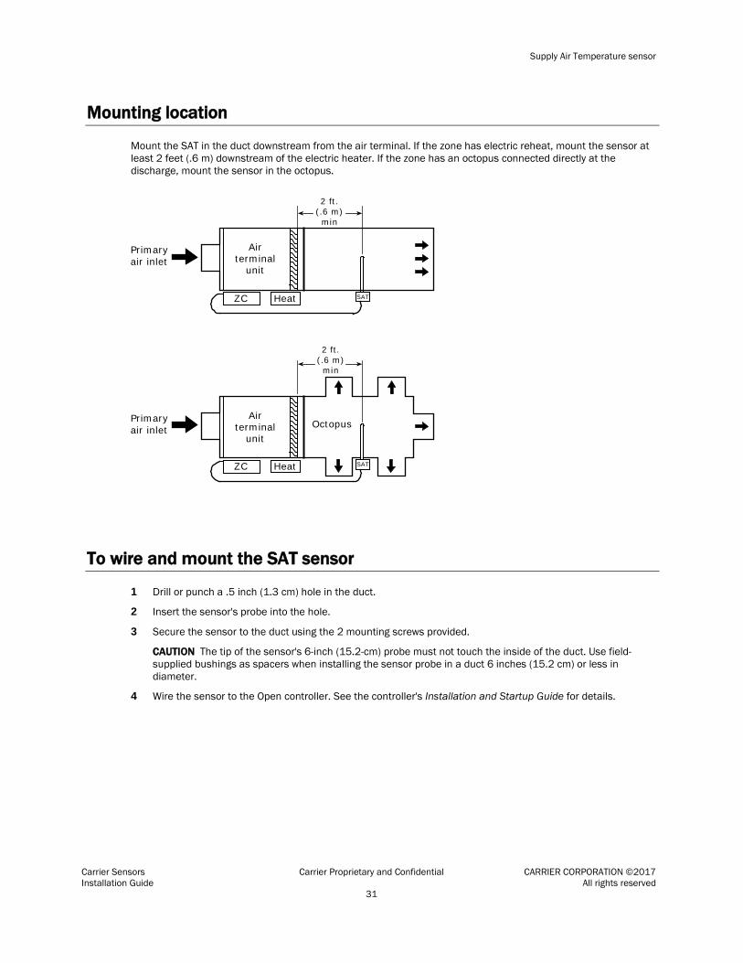
Mounting location
Mount the SAT in the duct downstream from the air terminal. If the zone has electric reheat, mount the sensor at least 2 feet (.6 m) downstream of the electric heater. If the zone has an octopus connected directly at the discharge, mount the sensor in the octopus.
ZC Heat
ZC Heat
Airterminal
unit
Airterminal
unitOctopus
SAT
SAT
2 ft.(.6 m)min
2 ft.(.6 m)min
Primaryair inlet
Primaryair inlet
To wire and mount the SAT sensor
1 Drill or punch a .5 inch (1.3 cm) hole in the duct.
2 Insert the sensor's probe into the hole.
3 Secure the sensor to the duct using the 2 mounting screws provided.
CAUTION The tip of the sensor's 6-inch (15.2-cm) probe must not touch the inside of the duct. Use field-supplied bushings as spacers when installing the sensor probe in a duct 6 inches (15.2 cm) or less in diameter.
4 Wire the sensor to the Open controller. See the controller's Installation and Startup Guide for details.
Duct Air Temperature sensor
Carrier Sensors Carrier Proprietary and Confidential CARRIER CORPORATION ©2017 Installation Guide All rights reserved 32
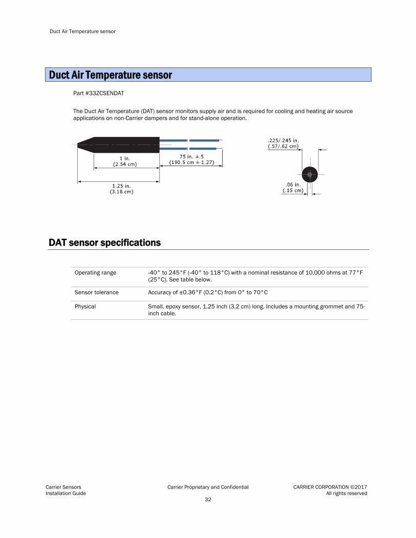
Part #33ZCSENDAT
The Duct Air Temperature (DAT) sensor monitors supply air and is required for cooling and heating air source applications on non-Carrier dampers and for stand-alone operation.
DAT sensor specifications
Operating range -40° to 245°F (-40° to 118°C) with a nominal resistance of 10,000 ohms at 77°F (25°C). See table below.
Sensor tolerance Accuracy of ±0.36°F (0.2°C) from 0° to 70°C
Physical Small, epoxy sensor, 1.25 inch (3.2 cm) long. Includes a mounting grommet and 75-inch cable.
Duct Air Temperature sensor
Duct Air Temperature sensor
Carrier Sensors Carrier Proprietary and Confidential CARRIER CORPORATION ©2017 Installation Guide All rights reserved 33
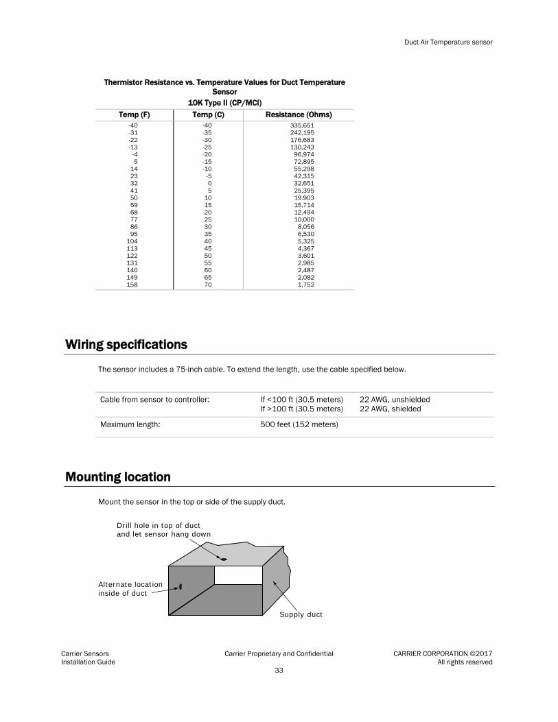
Thermistor Resistance vs. Temperature Values for Duct Temperature Sensor
10K Type II (CP/MCI) Temp (F) Temp (C) Resistance (Ohms)
-40 -31 -22 -13
-4 5
14 23 32 41 50 59 68 77 86 95
104 113 122 131 140 149 158
-40 -35 -30 -25 -20 -15 -10
-5 0 5
10 15 20 25 30 35 40 45 50 55 60 65 70
335,651 242,195 176,683 130,243
96,974 72,895 55,298 42,315 32,651 25,395 19.903 15,714 12,494 10,000
8,056 6,530 5,325 4,367 3,601 2,985 2,487 2,082 1,752
Wiring specifications
The sensor includes a 75-inch cable. To extend the length, use the cable specified below.
Cable from sensor to controller: If <100 ft (30.5 meters) 22 AWG, unshielded If >100 ft (30.5 meters) 22 AWG, shielded
Maximum length: 500 feet (152 meters)
Mounting location
Mount the sensor in the top or side of the supply duct.
Drill hole in top of ductand let sensor hang down
Alternate locationinside of duct
Supply duct

Duct Air Temperature sensor
Carrier Sensors Carrier Proprietary and Confidential CARRIER CORPORATION ©2017 Installation Guide All rights reserved 34
To wire and mount the DAT sensor
1 Drill or punch a .25 inch (.6 cm) hole in the top or side of the supply duct.
2 Insert the sensor's probe into the hole. The probe can touch side of duct.
3 Snap the grommet into the hole until it is secure.
4 Pull on the sensor's wiring until the sensor is snug against the grommet.
5 Wire the sensor to the Open controller. See the controller's Installation and Startup Guide for details.

Outdoor Air Temperature sensor
Carrier Sensors Carrier Proprietary and Confidential CARRIER CORPORATION ©2017 Installation Guide All rights reserved 35
Part #33ZCSENOAT
The outdoor air temperature (OAT) sensor monitors the temperature of the outside air before it enters the equipment.
NOTE If the sensor is to be installed in the outdoor air duct instead of an outdoor location, use a Primary Air Temperature (page 38) (Part #33ZCSENPAT) sensor instead of an OAT sensor.
2.81 in.(7.14 cm)
4.56 in.(11.58 cm)
4.92 in.(12.5 cm)
OAT sensor specifications
Operating range -40° to 245°F (-40° to 118°C) with a nominal resistance of 10,000 ohms at 77°F (25°C). See table below.
Sensor tolerance Accuracy of ±0.36°F (0.2°C) from 0° to 70°C
Physical Has a thermistor encased in a plastic resin probe that is enclosed in a PVC housing
Outdoor Air Temperature sensor

Outdoor Air Temperature sensor
Carrier Sensors Carrier Proprietary and Confidential CARRIER CORPORATION ©2017 Installation Guide All rights reserved 36
Thermistor Resistance vs. Temperature Values for Outdoor Air Temperature Sensor
10K Type II (CP/MCI) Temp (F) Temp (C) Resistance (Ohms)
-40 -31 -22 -13
-4 5
14 23 32 41 50 59 68 77 86 95
104 113 122 131 140 149 158
-40 -35 -30 -25 -20 -15 -10
-5 0 5
10 15 20 25 30 35 40 45 50 55 60 65 70
335,651 242,195 176,683 130,243
96,974 72,895 55,298 42,315 32,651 25,395 19.903 15,714 12,494 10,000
8,056 6,530 5,325 4,367 3,601 2,985 2,487 2,082 1,752
Wiring specifications
Cable from sensor to controller: If <100 ft (30.5 meters) 22 AWG, unshielded If >100 ft (30.5 meters) 22 AWG, shielded
Maximum length: 500 feet (152 meters)
Mounting location
For applications with an economizer, mount the sensor immediately upstream from the outdoor air damper where it will accurately sense the temperature of the outdoor air entering the mixing box.
For applications without an economizer, mount the sensor in the outdoor air duct near the outdoor air intake or on the northern exterior of the building.
Do not mount the sensor: • In direct sunlight • Near the exhaust from air-handling units or compressors • Near leakage drafts of indoor air • Near shrubbery or trees • Under direct water runoff

Outdoor Air Temperature sensor
Carrier Sensors Carrier Proprietary and Confidential CARRIER CORPORATION ©2017 Installation Guide All rights reserved 37
Building wall
.5-inch EMT malewaterproofconduit adaptor
Wire nuts
Outdoor airtemperature sensor
Wiring in.5-inch electricalmetal tubing (EMT)
7 ft.(min.)
Field wiring
To wire and mount the OAT sensor
1 Drill a 7/8" hole in a vertical wall.
2 Insert a .5-inch piece of electrical metal tubing (EMT).
3 Attach a .5-inch male waterproof conduit adapter to the end of the EMT.
4 Remove the knockout in the back of the OAT sensor.
5 Attach the sensor box to the conduit adapter using the adapter locking nut.
6 Replace sensor gasket and cover using the 2 screws provided.
7 Wire the sensor to the Open controller. See the controller's Installation and Startup Guide for details.

Primary Air Temperature sensor
Carrier Sensors Carrier Proprietary and Confidential CARRIER CORPORATION ©2017 Installation Guide All rights reserved 38
Part #33ZCSENPAT
The Primary Air Temperature (PAT) sensor monitors the supply air temperature. Use a PAT sensor if state or local code requires the use of conduit. If conduit is not required, you can use an SAT sensor.
6 in.(15.2 cm)probe
4 x 2 in.(10.2 x 5.1 cm)electrical box
PAT sensor specifications
Operating range -40° to 245°F (-40° to 118°C) with a nominal resistance of 10,000 ohms at 77°F (25°C). See table below.
Sensor tolerance Accuracy of ±0.36°F (0.2°C) from 0° to 70°C
Physical Has a thermistor encased with a 6-inch (15.2-cm) stainless steel probe. Has a 4x2-inch electrical box. Includes 2 mounting screws.
Primary Air Temperature sensor

Primary Air Temperature sensor
Carrier Sensors Carrier Proprietary and Confidential CARRIER CORPORATION ©2017 Installation Guide All rights reserved 39
Thermistor Resistance vs. Temperature Values for Primary Air Temperature Sensor
10K Type II (CP/MCI) Temp (F) Temp (C) Resistance (Ohms)
-40 -31 -22 -13
-4 5
14 23 32 41 50 59 68 77 86 95
104 113 122 131 140 149 158
-40 -35 -30 -25 -20 -15 -10
-5 0 5
10 15 20 25 30 35 40 45 50 55 60 65 70
335,651 242,195 176,683 130,243
96,974 72,895 55,298 42,315 32,651 25,395 19.903 15,714 12,494 10,000
8,056 6,530 5,325 4,367 3,601 2,985 2,487 2,082 1,752
Wiring specifications
Cable from sensor to controller: If <100 ft (30.5 meters) 22 AWG, unshielded If >100 ft (30.5 meters) 22 AWG, shielded
Maximum length: 500 feet (152 meters)
Mounting location
Mount the sensor in the top or side of the supply duct.
Drill hole in top of ductand let sensor hang down
Alternate locationinside of duct
Supply duct

Primary Air Temperature sensor
Carrier Sensors Carrier Proprietary and Confidential CARRIER CORPORATION ©2017 Installation Guide All rights reserved 40
To wire and mount the PAT sensor
1 Drill or punch a .5 inch (1.3 cm) hole in the duct.
2 Connect a .5 inch (1.3 cm) nominal field-supplied conduit between the zone controller enclosure and the junction box.
3 Pass the sensor wires through the conduit.
4 Insert the sensor's probe into the hole.
5 Secure the sensor to the duct using the 2 mounting screws provided.
CAUTION The tip of the sensor's 6-inch (15.2-cm) probe must not touch the inside of the duct.
6 Wire the sensor to the Open controller. See the controller's Installation and Startup Guide for details.

CO2 sensor
Carrier Sensors Carrier Proprietary and Confidential CARRIER CORPORATION ©2017 Installation Guide All rights reserved 41
Part #33ZCSPTCO2LCD-01 (Display model) Part #33ZCSPTCO2-01 (No display) Wall-mount or duct-mount Duct installation requires an Aspirator Box (Part #33ZCASPCO2) to house the CO2 sensor.
A CO2 sensor monitors carbon dioxide levels. As CO2 levels increase, the controller adjusts the outside air dampers to increase ventilation and improve indoor air quality. These sensors monitor temperature using a 10K thermistor, but are not capable of occupancy override.
The figure below shows ventilation rates for various CO2 setpoints when outside air with a typical CO2 level of 350 ppm is used.
20 CFM/person
5 CFM/person
500 700 900 1 100 1300 1500 1700 1900 2100 2300 2500
80
60
40
20
0
CO2 Concentration (PPM)
Airf
low
per
per
son
Out
side
air
(CFM
)
NOTES
• The sensor has a 4–20 mA output that is converted to 0–5 Vdc by a 250 Ohm, 1/4 watt, 2% tolerance resistor connected across the zone controller's CO2 input terminals.
• Do not use a relative humidity sensor and CO2 sensor on the same zone controller.
CO2 sensor

CO2 sensor
Carrier Sensors Carrier Proprietary and Confidential CARRIER CORPORATION ©2017 Installation Guide All rights reserved 42
CO2 sensor specifications
Method Dual Beam Absorption InfraredTM
Patented TEMA (time extended measurement algorithm) self-calibration software
Optional thermistor temperature measurement
Sample Method: Diffusion or flow-thru (50 to 100 ml/min)
Measurement range Analog Output: 0–2000 ppm factory default adjustable to 10,000 ppm
Digital display: 0–10,000 ppm Sensitivity: ± 10 ppm Resolution: ± 1 ppm
Sensor tolerance Accuracy: Typical Conditions: °60° to 90°F (15° to 32°C) 0–2000 ppm: ± 50 ppm or ± 3% of reading, whichever is greater 2000–10,000 ppm: ± 5% of reading
Extended Conditions : 32° to 122° (0° to 50°C) 0–2000 ppm: ± 100 ppm or ± 5%, whichever is greater 2000–10,000 ppm: ± 7% of reading, whichever is greater
Pressure Dependence: Add 0.13% of reading per mm Hg decrease from 760 (On board correction, user set)
Annual drift ± 10 ppm (negligible) with TEMA on ± 20 ppm typical with TEMA off
Response Time: 0–90% FS < 2 minutes
Warm-Up Time: 25 C < 2 minutes
Operating Conditions: 32° to 122°F (0° to 50°C) 0–95% RH (relative humidity), non-condensing
Storage Conditions: –40° to 158°F (–40° to 70°C)
Power Requires a dedicated 24 Vac, 3 Va transformer
Certification FCC Part 15 Class B
Calibration Interval: Five years/zero ppm gas offset adjust
Wiring specifications
Cable from sensor to controller: If <100 ft (30.5 meters) 22 AWG, unshielded If >100 ft (30.5 meters) 22 AWG, shielded
Maximum length: 500 feet (152 meters)

CO2 sensor
Carrier Sensors Carrier Proprietary and Confidential CARRIER CORPORATION ©2017 Installation Guide All rights reserved 43
Mounting location
A CO2 sensor can be wall-mounted or mounted in a return air duct. (Duct installation requires an Aspirator Box Accessory - Part #33ZCASPCO2.)
Wall mounting Mount the sensor: • Near the return air grill to sense the concentration of CO2 leaving the space • At least 3 feet (.9 m) from any corner
Do not mount the sensor: • Where it can have direct breath contact • In drafty areas such as near supply ducts, open windows, or fans • Over heat sources • Where it can be influenced by the supply air. The sensor gives inaccurate readings if the supply air blows
directly onto the sensor or the supply air does not have a chance to mix with the room air before it is drawn into the return air stream.
NOTE The sensor mounting plate accommodates the NEMA standard 2x4 in. standard single gang electrical box. However, the sensor can be mounted directly on the wall surface if local codes permit.
Duct mounting Mount the sensor: • In a duct that has a diameter or depth of at least 9 inches (22.9 cm) • At least 6 inches (15.2 cm) upstream or 15 inches (38.1 cm) downstream of a 90-degree turn in the return
air duct. The downstream location is preferred. • In the center of the duct • Where at least 1 foot (.3 m) of space in front of the sensor is free of obstruction
To wire and wall-mount the CO2 sensor
1 Turn the setscrew at the bottom of the sensor clockwise to release the sensor's cover from the mounting plate.
2 Lift the cover from the bottom, and then release it from the top fasteners.
3 Feed the wires from the electrical box through the opening in the center of the sensor mounting plate.
4 Use the 2 mounting screws provided to attach the mounting plate to the electrical box.
5 Wire the 24 Vac transformer to the sensor. See diagram below.
6 Turn the two Allen screws at the bottom of the unit counterclockwise to secure the cover to the mounting plate.
7 Wire the sensor to the Open controller. See the controller's Installation and Startup Guide for details.

CO2 sensor
Carrier Sensors Carrier Proprietary and Confidential CARRIER CORPORATION ©2017 Installation Guide All rights reserved 44
To controller
To wire and duct-mount the sensor
Duct installation requires the Aspirator Box Accessory (Part #33ZCASPCO2) to house the CO2 sensor.
To mount the aspirator box and sensor:
1 Drill a 1.25 inch (3.18 cm) hole in the return duct.
2 Remove the aspirator box cover.
3 Insert the aspirator box sampling tube into the hole.
4 Secure the box to the duct using 2 field-supplied #8 x 1" sheet metal screws.
5 Remove .5 inch (1.3 cm) conduit knockout, then install the conduit fittings.
6 Mount the CO2 sensor in the aspirator box using 2 field-supplied #8 x 32 machine screws.

CO2 sensor
Carrier Sensors Carrier Proprietary and Confidential CARRIER CORPORATION ©2017 Installation Guide All rights reserved 45
7 To wire the CO2 sensor, see the instructions above in To wire and wall-mount the CO2 sensor (page 43).
8 Install the aspirator box cover.

CO2/Temperature sensor
Carrier Sensors Carrier Proprietary and Confidential CARRIER CORPORATION ©2017 Installation Guide All rights reserved 46
Part #33ZCT55CO2 Part #33ZCT56CO2
A CO2/space temperature sensor houses two sensors in a single unit. This sensor uses Single Beam Absorption Infrared™ diffusion technology to monitor carbon dioxide (CO2) levels and has a 10K thermistor to measure space temperature. The controller uses this information to adjust the outside air dampers to provide proper ventilation and control space temperature.
Sensor Features
33ZCT55CO2
• CO2 sensor
• Space temperature sensor
• Push-button override
33ZCT56CO2
• CO2 sensor
• Space temperature sensor
• Push-button override
• Set point adjustment
NOTES
• The sensor has a 4–20 mA or 0–10 V output.
• Push button override
• Do not use a relative humidity sensor and CO2 sensor on the same zone controller.
CO2/Temperature sensor

CO2/Temperature sensor
Carrier Sensors Carrier Proprietary and Confidential CARRIER CORPORATION ©2017 Installation Guide All rights reserved 47
CO2/Temperature sensor specifications
Method Dual Beam Absorption InfraredTM
Patented TEMA (time extended measurement algorithm) self-calibration software
10K Temperature sensor
Sample Method: Diffusion
Measurement range Analog Output: 0–2000 ppm factory default adjustable to 10,000 ppm
Sensor tolerance Accuracy: Typical Conditions: °60° to 90°F (15° to 32°C) 0–2000 ppm: ± 110 ppm
Annual drift ± 10 ppm (negligible) with TEMA on ± 20 ppm typical with TEMA off
Response Time: 0–90% FS < 2 minutes
Warm-Up Time: 25 C < 2 minutes
Operating Conditions: 32° to 122°F (0° to 50°C) 0–95% RH (relative humidity), non-condensing
Storage Conditions: –4° to 158°F (–20° to 70°C)
Power 18-30 Vac RMS, 50/60 Hz - half wave rectified (dedicated)
18-42 Vdc polarity protected (dedicated)
1.75 Va maximum average power
2.75 Va peak power
Analog CO2 Output 4-20 mA (RLmax=500 Ohms) and 0–10 V (Source 100 mA, Sink 10 mA)
Temperature Sensor 10 kOhm Thermistor, 10 kOhm ± 2.5% at 77°F (25°C)
Temperature Control (#33ZCT56CO2 only)
Slide potentiometer position
Left stop
Right stop
Resistance
0 kOhms (+5 kOhms)
100 kOhms (± 10 kOhms)
Certification FCC Part 15 Class B
Calibration Interval: Five years/zero ppm gas offset adjust
Mounting 5 1/4 in. (13.3 cm) x 3 in. (7.6 cm) molded plastic. Includes 6x32 machine screws.

CO2/Temperature sensor
Carrier Sensors Carrier Proprietary and Confidential CARRIER CORPORATION ©2017 Installation Guide All rights reserved 48
Wiring specifications
Cable from sensor to controller: If <100 ft (30.5 meters) 22 AWG, unshielded If >100 ft (30.5 meters) 22 AWG, shielded
Maximum length: 500 feet (152 meters)
Mounting location
This sensor must be placed in an area that is representative of the conditional space or zone.
Wall mounting Mount the sensor: • On an internal wall near a return air grille or duct • At least 3 feet (.9 m) from any corner, 2 feet from an open doorway and 4 to 6 feet from the floor • Proximal to the wiring egress on the wall • Where the temperature operating limits are 32° to 122°F
Do not mount the sensor: • Close to a window, on an outside all, or next to a door leading to the outside • Close to or in direct airflow of areas such as open windows, drafts or over heat sources • In areas with poor circulation • Where it may be exposed to direct occupant breathing such as near water coolers or coffee machines NOTE The sensor mounting plate accommodates the NEMA standard 2x4 in. standard single gang electrical box. However, the sensor can be mounted directly on the wall surface if local codes permit.
To wire and mount the CO2/Temperature sensor
1 Disassemble the sensor into these three parts: sensor cover, sensor base and mounting plate.
2 Feed the wires from the electrical box through the opening in the center of the sensor mounting plate.
3 Use the 2 mounting screws provided to attach the mounting plate to the electrical box.
4 Run the wiring through the wire hole in the sensor base. See diagram below.
5 Reattach the sensor's base to the mounting plate, inserting the top first.
6 Separate the wires into two bundles: one bundle for the CO2 sensor wires (J4 and J1), the other bundle for the temperature sensor and CCN wires (J5 and J6).
7 Use the diagram below to connect the wiring to the sensor's J1, J4, J5, and J6 terminals.
NOTE On a large number of sensors, J6 was labeled incorrectly with CCN+ and CCN-. Ignore the labels on the circuit board and use the wiring diagram in this book.

CO2/Temperature sensor
Carrier Sensors Carrier Proprietary and Confidential CARRIER CORPORATION ©2017 Installation Guide All rights reserved 49
8 Push excess wire back through the hole.
9 Reattach the sensor's cover to the base and mounting plate.
10 Turn the two Allen screws counterclockwise to secure the cover to the mounting plate.
11 Wire the sensor to the Open controller. See the controller's Installation and Startup Guide for details.

Relative Humidity sensors
Carrier Sensors Carrier Proprietary and Confidential CARRIER CORPORATION ©2017 Installation Guide All rights reserved 50
Carrier offers 4 Relative Humidity sensors:
Sensor Usage
Space Relative Humidity sensor Part #33ZCSENSRH-02
Controls zone humidity (dehumidification) if the rooftop unit has a dehumidification device. If not, the sensor only monitors humidity.
Can output 0–5 or 0-10 Vdc or 4–20 mA.
Duct Relative Humidity sensor Part #33ZCSENDRH-02
Measures humidity in duct.
Relative Humidity sensors

Relative Humidity sensors
Carrier Sensors Carrier Proprietary and Confidential CARRIER CORPORATION ©2017 Installation Guide All rights reserved 51
Sensor Usage
Outdoor Relative Humidity sensor Part #33ZCSENORH-02
Measures outdoor humidity.
CAUTION Do not use a relative humidity sensor and CO2 sensor on the same zone controller.
Sensor specifications
Operating temperature 40° to 130°F (-4° to 54°C)
Humidity 0 to 99%, non-condensing
Sensor tolerance Accuracy at 25°C: ±2% RH from 10–80% ±3% RH from 80–99%
Power 18-36 Vdc 24 Vac half-wave rectified
Output
#33ZCSENSRH-02, #33ZCSENDRH-02, and #33ZCSENORH-02:
4-20 mA, 0-5 Vdc, and 0–10 Vdc
Physical Includes a 499 Ohm 1 Watt resistor for conversions of the 4–20 mA signal to a +2–10 Vdc output signal

Relative Humidity sensors
Carrier Sensors Carrier Proprietary and Confidential CARRIER CORPORATION ©2017 Installation Guide All rights reserved 52
Wiring specifications
Cable from sensor to controller: If <100 ft (30.5 meters) 22 AWG, unshielded If >100 ft (30.5 meters) 22 AWG, shielded
Maximum length: 500 feet (152 meters)
Mounting location
Mount this sensor... In this location
Space RH sensor • On an interior wall • Approximately 5 feet (1.5 meters) from the floor, beside the space temperature
sensor • At least 4 feet (1.2 meters) from any corner. Reduced airflow in corners results
in erratic sensor readings. • Vertically so that the Carrier logo is correctly oriented
Do not mount the sensor: • In drafty areas such as near heating or air-conditioning ducts, open windows, or
fans • Over heat sources such as baseboard heaters, radiators, or wall-mounted light
dimmers • In areas of excessive moisture, corrosive fumes, or vibration Sensors mounted in these areas will produce inaccurate readings.
NOTE The sensor mounting plate accommodates the NEMA standard 2x4 in. standard single gang electrical box. However, the sensor can be mounted directly on the wall surface if local codes permit.
Duct RH sensor The zone's return air duct
Outdoor RH sensor Where the sensor is protected from the elements and direct sunlight, such as under an eave

Relative Humidity sensors
Carrier Sensors Carrier Proprietary and Confidential CARRIER CORPORATION ©2017 Installation Guide All rights reserved 53
To wire and mount the Space RH sensors
1 Remove the sensor's cover from the mounting plate.
2 Feed the wires from the electrical box through the wire access hole in the center of the sensor mounting plate.
3 Use the 2 screws provided to attach the mounting plate to the electrical box.
4 Strip the outer jacket from the cable for at least 4 inches (10.2 cm). Strip .25 inch (.6 cm) of insulation from each wire.
5 Wire the unit for power. See Typical power wiring diagrams for Space RH sensors (page 55).
6 Wire the sensor to the Open controller. See diagrams below and the controller's Installation and Startup Guide for details.
Input Output Wiring diagram
18–36 Vdc 4–20 mA

Relative Humidity sensors
Carrier Sensors Carrier Proprietary and Confidential CARRIER CORPORATION ©2017 Installation Guide All rights reserved 54
Input Output Wiring diagram
18–36 Vdc or 21.6–26.4 Vac
0–10 Vdc
7 Reattach the cover to the mounting plate.
8 Turn the two Allen screws at the bottom of the unit counterclockwise to secure the cover to the mounting plate.
NOTES
• All wiring should be in accordance with all Local and National Electrical Code guidelines.
• If using shielded cable, connect only one end of the shield to ground at the controller. Connecting both ends to ground may cause a ground loop.

Relative Humidity sensors
Carrier Sensors Carrier Proprietary and Confidential CARRIER CORPORATION ©2017 Installation Guide All rights reserved 55
Typical power wiring diagrams for Space RH sensors
CAUTION If using a 24 Vac transformer, use an isolated transformer. If sharing the transformer with your controller or another device, be sure to connect all of the devices with the proper polarity, since most controllers are earth grounded. Failure to do so could cause a ground loop that could damage the devices.

Relative Humidity sensors
Carrier Sensors Carrier Proprietary and Confidential CARRIER CORPORATION ©2017 Installation Guide All rights reserved 56
To wire and mount the Duct RH sensor
1 Drill a .75 inch (1.9 cm) diameter hole in the duct where the sensor is to be mounted.
2 Insert the stainless steel probe into the hole until the foam contacts the duct, then attach the RH sensor using the 2 self-tapping screws provided.
3 Remove the cover.
4 On the probe unit, remove the knockout's inner ring.
5 If you are not using a .5 inch (1.3 cm) NPT conduit fitting, remove the knockout's outer ring. Tap the ring in 1 or 2 locations with a screwdriver, then remove the ring.
6 Install your conduit connectors or watertight fittings.
7 Wire the unit for power. See Typical power wiring diagrams for Duct RH and Outdoor RH sensors (page 58).
8 Wire the sensor to the Open controller. See diagrams below and the controller's Installation and Startup Guide for details.
Input Output Wiring diagram
18–36 Vdc 4–20 mA

Relative Humidity sensors
Carrier Sensors Carrier Proprietary and Confidential CARRIER CORPORATION ©2017 Installation Guide All rights reserved 57
Input Output Wiring diagram
18–36 Vdc or 21.6–26.4 Vac
0–10 Vdc
9 Place the sensor's cover onto the probe unit and gently turn until it is tight.
10 Verify that you are getting a humidity reading.
NOTE Allow up to 20 minutes after powering up for the sensor reading to stabilize.
To wire and mount the Outdoor RH sensor
See sensor diagram in To wire and mount the Duct RH sensor (page 56).
1 Use the 2 mounting screws provided to secure the sensor.
2 Remove the cover and install conduit connectors, watertight fittings, and/or 1/2” vent plug.
NOTE The inner ring will knock out first. Then tap the outer ring in 1 or 2 locations with a screwdriver to peel it out. The cover will be connected to the housing by the sensor leads.
3 At the sensor end of the cable, strip back the jacket from the cable for at least 3 inches. Strip 1/4 inch of insulation from each conductor. If using shielded cable, cut the shield and drain wire from the cable.
4 Wire the unit for power. See Typical power wiring diagrams for Duct RH and Outdoor RH sensors (page 58).
5 Wire the sensor to the Open controller. See diagrams below and the controller's Installation and Startup Guide for details.
Input Output Wiring diagram
15–36 Vdc 4–20 mA
18–36 Vdc or 21.6–26.4 Vac
0–10 Vdc

Relative Humidity sensors
Carrier Sensors Carrier Proprietary and Confidential CARRIER CORPORATION ©2017 Installation Guide All rights reserved 58
6 Place the cover onto the unit and gently turn until it is tight.
7 Verify that you are getting a humidity reading.
NOTE Allow up to 20 minutes after powering up for the sensor reading to stabilize.
Typical power wiring diagrams for Duct RH and Outdoor RH sensors

Relative Humidity sensors
Carrier Sensors Carrier Proprietary and Confidential CARRIER CORPORATION ©2017 Installation Guide All rights reserved 59
CAUTION If using a 24 Vac transformer, use an isolated transformer. If sharing the transformer with your controller or another device, be sure to connect all of the devices with the proper polarity, since most controllers are earth grounded. Failure to do so could cause a ground loop that could damage the devices.
Calibrating and troubleshooting relative humidity sensors
Troubleshooting the RH sensor
No reading Verify that:
• You have the correct supply voltage at the power terminal blocks.
• The wiring configuration and DIP switch settings are correct.
• All terminal screw connections are tight and that all wires are firmly in place.
Erratic readings
Verify that:
• All wires are terminated properly.
• The board does not have condensation on it.
• The input power is clean. In areas of high RF interference or noise, shielded cable may be needed to stabilize the signal.
Inaccurate readings
If you suspect the transmitter is not reading within the specified tolerance, contact the factory for assistance.
Using SW1 DIP switches to calibrate and troubleshoot This is a single point calibration only. All transmitters are factory-calibrated to meet/exceed published specifications. Field adjustment should not be necessary.
The DIP switch allows you to calibrate the sensor through software. Setting DIP switch 4 ON puts the transmitter into setup mode, allowing the increment and decrement to work. Once in setup mode, the output changes to 50% (5V for 0-10V, 12mA for 4-20mA). Each increment or decrement step causes the output to change by 0.2V for 0-10V, and 0.32mA for 4-20mA in setup mode. This shows how far offset the transmitter is. To see the starting point again, set DIP switch 1 to ON. This shows the 50% output again. When the unit is out of setup mode, the output returns to RH output.
When all calibration is completed, remember to place the switches back into positions that correspond to the output needed.
Normal Operating Condition
Setting DIP switch 4 ON puts the transmitter into setup mode. Once in setup mode, the output changes to 50% (5V for 0-10V, 12mA for 4-20mA).

Relative Humidity sensors
Carrier Sensors Carrier Proprietary and Confidential CARRIER CORPORATION ©2017 Installation Guide All rights reserved 60
0% RH Output
Transmitter outputs a 4 mA or 0 Vdc signal regardless of sensor reading. (For troubleshooting only.)
50% RH Output
Transmitter outputs a 12 mA, 2.5 Vdc, or 5 Vdc signal regardless of sensor reading. (For troubleshooting only.)
100% RH Output
Transmitter outputs a 20 mA, 5 Vdc, or 10 Vdc signal regardless of sensor reading. (For troubleshooting only.)
Increment RH Output
Shifts the RH output linearly up in 0.5% steps. Switch 4 must be set to ON first. After switch 4 is ON, each time switch 5 if set to ON, the RH output increases by 0.5%.
Decrement RH Output
Shifts the RH output linearly down in 0.5% steps. Switch 4 must be set to ON first. After switch 4 is ON, each time switch 6 if set to ON, the RH output decreases by 0.5%.
Reset to Original Calibration
Resets the RH output back to the original calibration. Switch 4 must be set to ON first. After switch 4 is ON, toggle switches 5 and 6 ON then OFF. After 5 and 6 are OFF, slide switch 4 OFF.
RH conversion formulas Use the following table to convert transmitter output signal to %RH.
Output
Example: If signal output is...
Calculation is...
4-20 mA
4 mA = 0% RH 20 mA = 100% RH
12 mA (12mA-4mA)/0.16 = 50% RH
0-10 Vdc
0 Vdc = 0% RH 10 Vdc = 100% RH
8 Vdc 8 Vdc/0.10 = 80%RH
0-5 Vdc
0 Vdc = 0% RH 5 Vdc = 100% RH
2 Vdc 2 Vdc/0.05 = 40% RH

Enthalpy switch/receiver and Enthalpy sensor
Carrier Sensors Carrier Proprietary and Confidential CARRIER CORPORATION ©2017 Installation Guide All rights reserved 61
Enthalpy switch/receiver - Part #33CSENTHSW Enthalpy sensor - Part #33CSENTSEN
Outdoor enthalpy control Requires a field-installed enthalpy switch/receiver. The enthalpy switch/receiver, mounted in the outdoor air intake, senses temperature and humidity of the surrounding air and calculates the enthalpy.
The enthalpy switch/receiver: • Energizes the relay output when the outdoor enthalpy is above 28 BTU/lb OR dry bulb temperature is above
75° F • De-energizes the relay output when the outdoor enthalpy is below 27 BTU/lb AND dry bulb temperature is
below 74.5° F. The relay output is wired to the unit economizer which opens or closes based on the output of the switch.
Differential enthalpy control Requires an enthalpy switch/receiver and an enthalpy sensor. The enthalpy switch/receiver, mounted in the outdoor air intake, calculates outdoor air enthalpy. The enthalpy sensor, mounted in the return airstream, calculates the indoor air enthalpy.
The enthalpy switch/receiver energizes: • The HI Enthalpy relay output when the outdoor enthalpy is greater than the indoor enthalpy • The LOW Enthalpy terminal when the outdoor enthalpy is lower than the indoor enthalpy The relay output is wired to the unit economizer which opens or closes based on the output of the switch.
NOTE The enthalpy is calculated using an average altitude of 1000 ft above sea level.
Enthalpy switch/receiver
33CSENTHSWRETURN AIR
ENTH SENSOR- +
Model #: HH57ZC003Power: 24 VACOutput: 10 A Form 1C Relay w/ 24 VAC Sourced Power
HI LOW GND 24Enthalpy VAC
4-20mA In
24-36VDCout
4.25 in.(10.8 cm)
3.35 in.(8.5 cm)
3.75 in.(9.5 cm)
Enthalpy sensor
33CSENTSEN
+ -
Model #: HH57ZC001Power: 24 to 36 VDCSpan: 0 to 50 BTU/lbOutput: 4 to 20 mA
4-20mA In
24-36VDCout
4.25 in.(10.8 cm)
3.35 in.(8.5 cm)
3.75 in.(9.5 cm)
Enthalpy switch/receiver and Enthalpy sensor

Enthalpy switch/receiver and Enthalpy sensor
Carrier Sensors Carrier Proprietary and Confidential CARRIER CORPORATION ©2017 Installation Guide All rights reserved 62
Enthalpy switch/sensor specifications
The following specifications are the same for the switch/receiver and sensor unless noted.
Supply voltage Switch/Receiver: Sensor:
24 Vac ±15% 24 to 36 Vdc
Operating range -40° to 140°F (-40° to 60°C)
Operating relative humidity 0 to 100%, non-condensing
Output Switch/Receiver: Sensor:
Sourced 24 Vac through 10 Amp Form 1C relay 2-wire, 4–20 mA loop powered
Enthalpy range Sensor only 0–50 Btu/lb
Enthalpy accuracy ±1 Btu/lb at 77°F (25°C)
Temperature accuracy ±0.36°F (0.2°C) from 32 to 158°F (0 to 70°C)
Relative humidity accuracy ±35 at 77°F (25°C)
Sensitivity 0.1% RH
Repeatability 0.5% RH
Hysteresis < 0.4% RH
Stability < 2% drift over 5 years
Wiring specifications
Cable from sensor to controller: If <100 ft (30.5 meters) 22 AWG, unshielded If >100 ft (30.5 meters) 22 AWG, shielded
Maximum length: 500 feet (152 meters)
Mounting location
Mount the enthalpy switch/receiver in the outdoor air intake.
Mount the enthalpy sensor in the return air duct.
Do not mount the enthalpy switch/receivers and sensors where they could be exposed to outdoor elements such as rain or snow. These units are not NEMA 4 enclosures.

Enthalpy switch/receiver and Enthalpy sensor
Carrier Sensors Carrier Proprietary and Confidential CARRIER CORPORATION ©2017 Installation Guide All rights reserved 63
To wire and mount the switch/sensor
For Outdoor Enthalpy Control 1 To mount the enthalpy switch/receiver, insert 2 field-supplied 8 x 3/4-in. TEK screws through its side holes.
2 Remove the 4 screws holding the cover on, then remove cover.
3 Set the M1 to M3 jumper to M2. Leave the other jumper on Off.
4 Replace the cover and the 4 screws.
5 Connect the GND and 24 Vac terminals on the enthalpy switch/receiver to the controller's power terminals.
6 Connect the HI or LOW terminals on the enthalpy switch/receiver to the controller's J2-6 input.

Enthalpy switch/receiver and Enthalpy sensor
Carrier Sensors Carrier Proprietary and Confidential CARRIER CORPORATION ©2017 Installation Guide All rights reserved 64
For Differential Enthalpy Control 1 To mount the enthalpy sensor, insert 2 field-supplied 8 x 3/4-in. TEK screws through its side holes.
2 Repeat step 1 to mount the enthalpy switch/receiver.
3 On the switch/receiver, remove the 4 screws holding the cover on, then remove cover.
4 Set the M1 to M3 jumper to M2. Leave the other jumper on Off.
NOTE The enthalpy sensor's jumpers should be left at their factory settings of M3 and Off.
5 Replace the switch/receiver's cover and the 4 screws.
6 Wire the sensor to the switch/receiver. See figure below.
7 Connect the GND and 24 Vac terminals on the enthalpy switch/receiver to the controller's power terminals.
8 Connect the HI or LOW terminals on the enthalpy switch/receiver to the controller's J2-6 input.

Appendix: i-Vu® Control System Wiring Specifications and Recommended Vendors
Carrier Sensors Carrier Proprietary and Confidential CARRIER CORPORATION ©2017 Installation Guide All rights reserved 65
Wiring specifications Recommended vendors & part numbers
Wire type
Description
Connect Air International
Belden
Ramcorp
Contractors Wire & Cable
MS/TP and ARC156 network (RS-485)
22 AWG, single twisted shielded pair, low capacitance, CL2P, TC foam FEP, plenum rated. See MS/TP Installation Guide for specifications.
W221P-2227 -- 25160PV CLP0520LC
MS/TP and ARC156 network (RS-485)
24 AWG, single twisted shielded pair, low capacitance, CL2P, TC foam FEP, plenum rated. See MS/TP Installation Guide for specifications.
W241P-2000FB 82841 25120-OR --
Rnet 4 conductor, unshielded, CMP, 18 AWG, plenum rated.
W184C-2099BLB 6302UE 21450 CLP0442
Power - 24 Vac
2 conductor, CM, 18 AWG, unshielded.
W181P-2051 5300UE 21251 CLP0440
Analog & discrete sensor wiring < 100 ft
Single twisted pair, unshielded, CM, 22AWG, plenum rated.
W221P-2005 6500UE 21281 CLP0410
Analog & discrete sensor wiring 100–500 ft
Single twisted shielded pair, CM, 22AWG, plenum rated.
W221P-2044 6500FE 21280 CLP0520
Appendix: i-Vu® Control System Wiring Specifications and Recommended Vendors

Document revision history
Carrier Sensors Carrier Proprietary and Confidential CARRIER CORPORATION ©2017 Installation Guide All rights reserved 66
Important changes to this document are listed below. Minor changes such as typographical or formatting errors are not listed.
Date Topic Change description Code*
8/2/17 Alt space temp sensor specifications SAT sensor specifications DAT sensor specifications OAT temp sensor specifications PAT sensor specifications
Corrected all 10K Type III (CP/MCI) to Type II. C-TS-CP-E-ZL
3/10/16 Specifications Added drift statement to Humidity specification. X-TS-EE-F 5/28/15
Introduction to Carrier sensors Carrier® ChillerVu™ added and WSHP Open removed from table C-TS-RD-E
ZS sensors - CO2 sensor installation New section C-TS-RD-E
11/24/14 Power requirements Made corrections to wiring diagram X-TS-JM-O
8/6/14 To address a ZS Sensor Changed ZS Sensor default address to 1 from 0. C-TS-RD-O
Introduction to Carrier sensors Added MPC Open XP controller to the table C-D Entire document BACview removed C-D
Introduction to Carrier Sensors ZS Sensors added to the table C-TS-RD-E * For internal use only
Document revision history

Index
Carrier Sensors Carrier Proprietary and Confidential CARRIER CORPORATION ©2017 Installation Guide All rights reserved 67
# #33CSENTHSW • 61 #33ZCASPCO2 • 41 #33ZCSENDAT • 32 #33ZCSENOAT • 35 #33ZCSENORH-02 • 13 #33ZCSENPAT • 29, 35, 38 #33ZCSENSAT • 29, 38 #33ZCSENSRH-02 • 48 #33ZCT55CO2 • 46 #33ZCT55SPT • 22 #33ZCT56CO2 • 46 #33ZCT56SPT • 22 #33ZCT59SPT • 22 #3CSENTSEN • 61 #SPP • 13 #SPPF • 13 #SPPL • 13 #SPS • 13
A Alternate space temperature sensor • 22 aspirator box • 41, 44
C CO2 sensor • 41 CO2/Temperature sensor • 3, 46
D Duct Air Temperature sensor • 32 Duct sensors
Duct Air Temperature sensor • 32 Enthalpy sensor • 61 Enthalpy switch/receiver • 61 Outdoor Air Temperature sensor • 35 Primary Air Temperature sensor • 29, 35, 38 Supply Air Temperature sensor • 29, 38
E Enthalpy sensor • 61 Enthalpy switch/receiver • 61
H Humidity sensor • 3
O Outdoor Air Temperature sensor • 35 outdoor sensors
Outdoor Air Temperature sensor • 35
P Primary Air Temperature sensor • 29, 35, 38
R Rnet • 13, 15, 16 Rnet wiring specifications • 16
S space temperature sensors • 13, 22 SPT Plus • 13, 15, 18, 21 SPT Pro • 13, 15, 18, 21 SPT Pro Plus • 13, 15, 18, 21 SPT sensors • 13 SPT Standard • 13, 15, 21 Supply Air Temperature sensor • 29, 38
T T55 / T56 • 22, 46 temperature sensors
Alternate space temperature sensor • 22 CO2/Temperature sensor • 3, 46 Duct Air Temperature sensor • 32 Outdoor Air Temperature sensor • 35 Primary Air Temperature sensor • 29, 35, 38 SPT sensors • 13 Supply Air Temperature sensor • 29, 38 ZS Sensors • 3
W wall-mounted sensors
CO2 sensor • 41 CO2/Temperature sensor • 3, 46
Wiring specifications Rnet • 16
Z ZS • 3 ZS Plus • 3 ZS Pro • 3
Index


CARRIER CORPORATION ©2017 A member of the United Technologies Corporation family · Stock symbol UTX · Catalog No. 11-808-423-01 · 8/2/2017