Embed Size (px)
Citation preview

1
Carrier to Interference (C /I ratio)
Calculations

Outlines the C/I calculation methodology for interference assessment under No.11.32A w.r.t. coordination of networks under No. 9.7 (i.e. GSO vs GSO satellite networks) The ROP defines
how the different type of carriers are categorized according to the class of emission (itemC.7 a Annex 2 in Appendix 4)
which criteria to apply for different combinations of carrier types
the interference adjustment factor to consider for different combinations of carrier types
when C/N objective (submitted in accordance with Appendix 4(Annex 2 item C.8.e.1) or Calculated C/N is used
assumptions to make when dealing with composite interference from a number of narrow band carriers
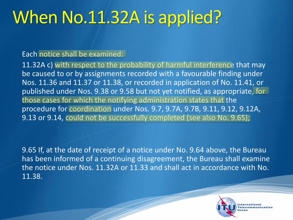
When No.11.32A is applied?
Each notice shall be examined:
11.32A c) with respect to the probability of harmful interference that may be caused to or by assignments recorded with a favourable finding under Nos. 11.36 and 11.37 or 11.38, or recorded in application of No. 11.41, or published under Nos. 9.38 or 9.58 but not yet notified, as appropriate, for those cases for which the notifying administration states that the procedure for coordination under Nos. 9.7, 9.7A, 9.7B, 9.11, 9.12, 9.12A, 9.13 or 9.14, could not be successfully completed (see also No. 9.65);
9.65 If, at the date of receipt of a notice under No. 9.64 above, the Bureau has been informed of a continuing disagreement, the Bureau shall examine the notice under Nos. 11.32A or 11.33 and shall act in accordance with No. 11.38.

More complex than delta T/T and more detailed Used by Bureau for No.11.32A examination* Widely accepted method for assessment of interference especially between geostationary satellite networks Widely used by Administrations for coordination of their satellite networks
*GSO vs GSO satellite networks

COORDINATION MEETING
Occasion for information exchange
Agreement of Assumptions
Agreement of Criteria
Agreement of Operating or Desired C/Ns
Agreement of Calculation Method
Agreement of set of parameters to be used
More detailed information on service areas, type of carriers, antenna radiation patterns, implementation dates, transponder plan, etc.
Radio Regulations and ITU Recommendations are often used as the main reference

ITU-BR Space Regulatory Workshop Tehran, 14-19 June 2008
WHAT’S IMPORTANT?
Understanding the basics and concepts of C/I facilitates
C/I generation
Development of C/I calculation tool
Summarization and interpretation of results
Analysis and finding interference mitigation solutions

Examine Probability of Harmful Interference
Negative Margin
Potential for
Harmful Interference
Margin
Positive or Zero
Margin
No Harmful Interference
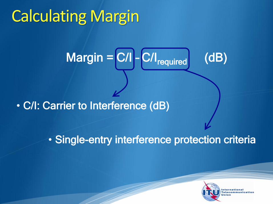
Calculating Margin
• C/I: Carrier to Interference (dB)
• Single-entry interference protection criteria
Margin = (dB) C/I C/Irequired –

Finding C/I Required
1.C/N: Carrier to Noise (dB)
2.Type of Carrier
C/Irequired
• Single-entry interference protection criteria
• §3.1 of Section B3 of Rules of Procedure
Margin = (dB) C/I –

Finding C/I Required Interfering
Wanted
TV/FM or Other Digital
Analogue
(Other than
TV/FM)
TV/FM C/N + 14 (dB)
Digital
If BWw <= BWeqi then
C/N + 5.5 + 3.5*log(BWw) (dB) C/N + 12.2 (dB)
else if BWw > BWeqi then
C/N + 12.2 (dB)
Analogue
(Other than
TV/FM)
11.4 + 2*log (BWw) (dB) C/N + 12.2 (dB)
Other 11.4 + 2*log (BWw) (dB) C/N + 14 (dB)
Source: Table 2 in Section B3 of Rules of Procedures, ITU-R S.741-2
BWw: Necessary bandwidth of wanted carrier (MHz)
BWeqi: Equivalent bandwidth of interfering carrier (MHz)
C/N: Carrier to Noise ratio (dB)

Calculate C/N
Maximum Peak Power PMax
Necessary Bandwidth of Emission B
Maximum Earth Station Antenna Gain GES Max
Off-axis Satellite Antenna Gain G(q)Sat
Free Space Loss (assigned frequency) FSL
Receiver System Noise Temperature T
Service Area
B (↑ Emiss)
P ES Max
G Tx ES Max
FSL (↑ Freq)
G(q) Rx Sat
T Sat
P Sat Max
B (↓ Emiss)
G(q) Tx Sat
FSL (↓ Freq)
G Rx ES Max
T ES
Finding C/I Required

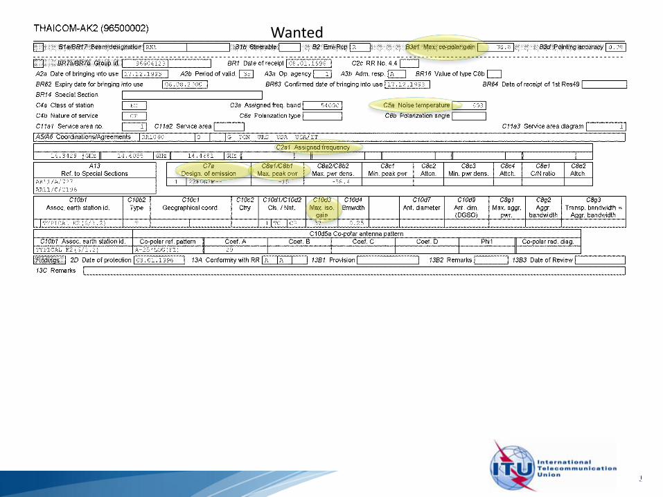
Where to get these information?
Beam Level
Group Level
Sub-Group or Frequency Assignment Level

Maximum Peak Power PMax
Necessary Bandwidth of Emission B
Maximum Earth Station Antenna Gain GES Max
Off-axis Satellite Antenna Gain G(q)Sat
Free Space Loss (assigned frequency) FSL
Receiver System Noise Temperature T
Service Area
C8a1/C8b1
C7a
C10d3
C2a1
B3a + B3b
C5a/C10d6
C11a
Appendix
4
Calculate C/N Finding C/I Required
B (↑ Emiss)
P ES Max
G Tx ES Max
FSL (↑ Freq)
G(q) Rx Sat
T Sat
P Sat Max
B (↓ Emiss)
G(q) Tx Sat
FSL (↓ Freq)
G Rx ES Max
T ES

C/N = P Max + G ES Max + G(q) Sat – FSL(Freq) – ( k + T + B(Emiss) ) (dB)
k, Boltzmann constant = -228.6 dBW/K/Hz
C, Carrier power N, Noise power
FSL = 10log10(4pdf/c)2
Calculate C/N Finding C/I Required
B (↑ Emiss)
P ES Max
G Tx ES Max
FSL (↑ Freq)
G(q) Rx Sat
T Sat
P Sat Max
B (↓ Emiss)
G(q) Tx Sat
FSL (↓ Freq)
G Rx ES Max
T ES

C ↑ = PES Max+ GTx ES Max+ G(q)Rx Sat- FSL(↑ Freq)
C ↓ = PSat Max+ G(q)Tx Sat+ GRx ES Max- FSL(↓ Freq)
- (k + TSat + B(↑ Emiss)) /N (dB)
- (k + TES + B(↓ Emiss))
/N (dB)
Uplink C/N
Downlink C/N
Calculate C/N Finding C/I Required
B (↑ Emiss)
P ES Max
G Tx ES Max
FSL (↑ Freq)
G(q) Rx Sat
T Sat
P Sat Max
B (↓ Emiss)
G(q) Tx Sat
FSL (↓ Freq)
G Rx ES Max
T ES

1
FSL = 20 (log f + log d ) + 32.45 dB
where :
f : frequency (mHz)
d : distance (km)
where:
d = 42644(1-0.2954.cos)0.5
where:
cos= cos x cos
where : = latitude of earth station = difference in longitude btw satellite and earth station
Free Space Loss (Annex II of AP8)

Select C/N Finding C/I Required
Submitted Calculated
Existing network
(examined/published)
Incoming network
(new/under exam)
If C/Nsubmitted < C/Ncalculated

Check Carrier Type
Example:
Necessary bandwidth
36M0G7W--
Source: Item C.7 Annex 2 of Appendix 4, Section II of Appendix 1
Class of Emission
1st Symbol: Type of modulation of the
main carrier
2nd Symbol: Nature of signal(s)
modulating the main carrier
3rd Symbol: Type of info to be
transmitted
Finding C/I Required

Finding C/I Required
To summarize:
• From Appendix 4 data, find C/N
• From emission, find carrier type
• From Table 2 in Section B3 of Rules of
Procedure, find C/I Required
C/Irequired Margin = (dB) C/I –

Finding C/I
C/I: Carrier to Interference (dB)
C/I = C/Ib - Ia
1. C/Ib: Basic calculated C/I (dB)
2. Ia: Interference adjustment factor (dB)
C/I Margin = (dB) C/Irequired –

Calculate C/I basic
P ES Max
G Tx ES Max
G(q) Rx Sat
C ↑ = P ES Max + G Tx ES Max + G(q) Rx Sat – FSL(↑ Freq) (dBW)
I ↑ = P’ ES Max + G’(f) Tx ES + G(q’) Rx Sat – FSL’(↑ Freq) (dBW)
FSL (↑ Freq)
P’ ES Max
G’(f) Tx ES
FSL’ (↑ Freq)
G(q’) Rx Sat
C/I ↑ = C ↑ - I ↑ (dB)
Source: ITU-R S.740
Finding C/I
f

1
Topocentric Angular Separation Between Two Satellites
(Annex I of AP8)
qt = arc cos d12+d2
2 - (84332 sin (qg/2))2
2d1.d2
Where
d1 and d2 are the distances (km), from earth station to the two satellites separately
qg is the geocentric angular separation in degrees between the two satellites, taking the longitudinal station-keeping tolerances into account

Annex 3 of Appendices 7 and 8 of the Radio Regulations
ITU-R S.580-6
ITU-R S.465-6
ITU-R BO.1900
ITU-R M.694-1
ITU-R BO.1213-1
ITU-R Bo.1295
Antenna reference patterns

-20
-10
0
10
20
30
40
50
60
70
Ang
le 24.
5 79.
5 1214
.5 1719
.5 2224
.5 2729
.5 3234
.5 3739
.5 4244
.5 4749
.5 5254
.5 5759
.5 6264
.5 6769
.5 7274
.5 7779
.5 8284
.5 8789
.5 9294
.5 97
REC-465
REC-580
Pattern1 Pattern2 Freq (MHz) Gmax (dBi)
REC-465 REC-580 7265 60

Calculate C/I basic
C ↓ = P Sat Max + G(q) Tx Sat + G Rx ES Max – FSL(↓ Freq) (dBW)
I ↓ = P’ Sat Max + G’(f) Tx Sat + G(q’) Rx ES – FSL’(↓ Freq) (dBW)
C/I ↓ = C ↓ - I ↓ (dB)
P Sat Max
FSL (↓ Freq)
G(q) Tx Sat
G Rx ES Max
FSL’ (↓ Freq)
P’ Sat Max
G’(f) Tx Sat
G(q’) Rx ES
Source: ITU-R S.740
Finding C/I
q’

Finding C/I
C/I: Carrier to Interference (dB)
C/I = C/Ib - Ia
1. C/Ib: Basic calculated C/I (dB)
2. Ia: Interference adjustment factor (dB)
C/I Margin = (dB) C/Irequired –

Get Adjustment Factor Wanted
Interfering
Digital
Analogue
(Other than
TV/FM)
Other TV/FM
Digital METHOD 1: Wanted Bandwidth (BW) to Interfering BW
Overlapping Ratio Adjustment
TV/FM METHOD 2:
Wanted BW to
Interfering Equivalent BW
Overlapping Ratio
Adjustment
METHOD 1: Co-freq.
METHOD 3: Non co-freq.
(Relative Protection Ratio)
Analogue
(Other than
TV/FM) METHOD 2
Other
Source: Table 1 in Section B3 of Rules of Procedures, ITU-R S.741-2
Finding C/I

Get Adjustment Factor Method 1:
Wanted Signal
Interfering Signal
Ia = 10log10 (BWoverlap / BWi)
= 10log10 (BWw / BWi)
< 0 = Improvement!
BW: Necessary
Bandwidth (Hz)
Finding C/I
BWw
BWi

Get Adjustment Factor
Wanted Signal
Interfering Signal
Ia = 10log10 (BWoverlap / BWi)
= 10log10 (BWi / BWi)
= 0 = No Improvement!
BW: Necessary
Bandwidth (Hz)
Finding C/I
Method 1: BWw
BWi

Get Adjustment Factor
Wanted Signal
BWw
BWi
PDmax
Pmax Pmax: Total Peak
Power (W)
PDmax: Maximum
Power Density
(W/Hz)
Interfering Signal (Analogue with
Gaussian
distribution)
BW: Necessary
Bandwidth (Hz)
Finding C/I
Method 2:
BWeq = Pmax / PDmax
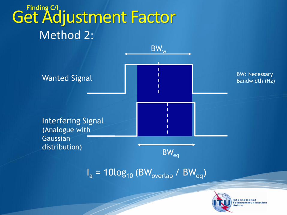
Get Adjustment Factor
Wanted Signal
Interfering Signal (Analogue with
Gaussian
distribution)
Ia = 10log10 (BWoverlap / BWeq)
BW: Necessary
Bandwidth (Hz)
Finding C/I
Method 2: BWw
BWeq

Get Adjustment Factor
Interfering Signal
(TV/FM)
Wanted Signal
(TV/FM)
Frequency Offset
Relative Protection Ratio adjustment factor is
• derived from protection masks using frequency offset
• a function of overlapping bandwidths of wanted and
interfering signals
Finding C/I
Method 3:

Finding C/I
To summarize:
• From Appendix 4 data, find basic calculated C/Ib
• From Table 1 in Section B3 of Rules of
Procedure, find Interference Adjustment Factor Ia
• C/I = C/Ib - Ia
C/I Margin = (dB) C/Irequired –

Wanted Signal
Interfering Signal
Finding C/I
Multiple interfering narrowband carriers
• Interfering transponder fully loaded with N
narrowband carriers
• N is maximized by transponder bandwidth (item
C.3.a of Appendix 4) and maximum total peak power
(item C.8.d.1) or the maximum aggregate power
supplied to the E/S transmit antenna(item C.8.g.1)

Calculating Margin
• Positive or Zero Margin:
No harmful interference
Margin = (dB) C/I C/Irequired –
• Negative Margin:
Potential for harmful interference

36
Results

EXAMPLE 1
1 ITU-BR Space Regulatory Workshop Tehran, 14-19 June 2008
Wanted

Interfering

THAICOM-AK2 Receive Beam RK1

INTERSPUTNIK-75E-Q Receive Beam DKS

Interfering
`Wanted
Interfering
`THAICOM-AK2
INTERSPUTNIK-75E-Q
ITU-BR Space Regulatory


EXAMPLE 2

Wanted

Wanted

Interfering

THAICOM-AK2 Transmit Beam TK1

INTERSPUTNIK-75E-Q Transmit Beam 002


Mitigation Methods
• Improve sidelobe performance
• better performance antenna
• use larger antennas
• Limit service area
• Power reduction
• Limitation of number of carriers
• Analog to digital
• Frequency planning
• Transponder planning
• Polarization
•Establishment of point of contacts / procedures
•Business collaboration – JVs
•Etc.

Constraints Cost
Feasibility
Types of services
Existing users
Flexibility
Quality of Service
Type of Applications (DTH, VSAT, TV Headend,etc )
Design considerations
Etc.